EP2425685B1 - In-situ plasma/laser hybrid scheme - Google Patents
In-situ plasma/laser hybrid scheme Download PDFInfo
- Publication number
- EP2425685B1 EP2425685B1 EP10770480.1A EP10770480A EP2425685B1 EP 2425685 B1 EP2425685 B1 EP 2425685B1 EP 10770480 A EP10770480 A EP 10770480A EP 2425685 B1 EP2425685 B1 EP 2425685B1
- Authority
- EP
- European Patent Office
- Prior art keywords
- direct current
- precursor
- cathode
- plasma
- current plasma
- Prior art date
- Legal status (The legal status is an assumption and is not a legal conclusion. Google has not performed a legal analysis and makes no representation as to the accuracy of the status listed.)
- Active
Links
Images


Classifications
-
- H—ELECTRICITY
- H05—ELECTRIC TECHNIQUES NOT OTHERWISE PROVIDED FOR
- H05H—PLASMA TECHNIQUE; PRODUCTION OF ACCELERATED ELECTRICALLY-CHARGED PARTICLES OR OF NEUTRONS; PRODUCTION OR ACCELERATION OF NEUTRAL MOLECULAR OR ATOMIC BEAMS
- H05H1/00—Generating plasma; Handling plasma
- H05H1/24—Generating plasma
- H05H1/26—Plasma torches
- H05H1/32—Plasma torches using an arc
- H05H1/42—Plasma torches using an arc with provisions for introducing materials into the plasma, e.g. powder or liquid
-
- G—PHYSICS
- G21—NUCLEAR PHYSICS; NUCLEAR ENGINEERING
- G21K—HANDLING OF PARTICLES OR IONISING RADIATION NOT OTHERWISE PROVIDED FOR; IRRADIATION DEVICES; GAMMA RAY OR X-RAY MICROSCOPES
- G21K5/00—Irradiation devices
-
- H—ELECTRICITY
- H05—ELECTRIC TECHNIQUES NOT OTHERWISE PROVIDED FOR
- H05G—X-RAY TECHNIQUE
- H05G2/00—Apparatus or processes specially adapted for producing X-rays, not involving X-ray tubes, e.g. involving generation of a plasma
-
- H—ELECTRICITY
- H05—ELECTRIC TECHNIQUES NOT OTHERWISE PROVIDED FOR
- H05H—PLASMA TECHNIQUE; PRODUCTION OF ACCELERATED ELECTRICALLY-CHARGED PARTICLES OR OF NEUTRONS; PRODUCTION OR ACCELERATION OF NEUTRAL MOLECULAR OR ATOMIC BEAMS
- H05H1/00—Generating plasma; Handling plasma
- H05H1/24—Generating plasma
- H05H1/26—Plasma torches
- H05H1/32—Plasma torches using an arc
- H05H1/34—Details, e.g. electrodes, nozzles
- H05H1/3478—Geometrical details
Definitions
- the present disclosure relates to direct current (DC) plasma processing and, more particularly, relates to a modified direct current plasma apparatus and methods for improved coating results using direct current plasma processing.
- DC direct current
- the material to be deposited (also known as feedstock) - typically as a powder, a liquid, a liquid suspension, or the like - is introduced into a plasma jet emanating from a plasma torch or gun.
- the temperature is on the order of 10,000 K
- the material is melted and propelled towards a substrate.
- the molten/semi-molten droplets flatten, rapidly solidify and form a deposit and, if sufficient in number, a final layer.
- the deposits remain adherent to the substrate as coatings, although free-standing parts can also be produced by removing the substrate.
- Direct current (DC) plasma processing and coating is often used in many industrial technology applications.
- a conventional direct current plasma apparatus 100 generally comprises a housing 110 having a cathode 112 (which is negatively charged) and an anode 114 (which is positively charged).
- a plasma gas is introduced along an annular pathway 116 to a position downstream of cathode 112 and generally adjacent anode 114.
- An electrical arc is established and it extends from the cathode 112 to the anode 114 and generates the plasma gas to form a hot gas jet 118.
- this electrical arc rotates on the annular surface of the anode 114 to distribute the heat load.
- a precursor 120 such as in the form of a powder or a liquid, is fed from a position downstream of anode 114 and external to the plasma jet 118 into the jet boundary. This process is generally referred to as radial injection.
- the powders (solid) and/or droplets (liquid) within the precursor 120 are typically entrained into the plasma jet 118 and travel with it, eventually melting, impacting, and being deposited on a desired target.
- the powders are typically presynthesized by another process into a predetermined chemistry and solidified form and are typically sized on the order of microns.
- the liquid droplets are typically of two types-namely, a first type where the liquid droplets contain very fine powders (or particles), which are presynthesized by another process into solid form being of submicron or nanometer size, suspended in a liquid carrier; and a second type where liquid droplets contain a chemical dissolved in a solvent, wherein the chemical eventually forms the final desired coating material.
- the liquid droplets are entrained in the plasma jet 118, causing the liquid carrier to evaporate and the fine particles to melt.
- the entrained melted particles then impact on a target, thereby forming the coating.
- This approach is also known as "suspension approach”.
- the solid powder injection approach is used to form microcrystalline coatings, and both of the liquid approaches are used to form nanostructured coatings.
- direct current plasma processing suffers from a number of disadvantages.
- the precursor materials are typically exposed to different temperature history or profiles as they travel with the plasma jet.
- the core of the plasma jet is hotter than the outer boundaries or periphery of the plasma jet, such that the particles that get dragged into the center of the jet experience the maximum temperature.
- the particles that travel along the periphery experience the lowest temperature.
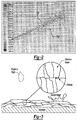
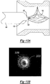
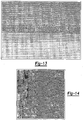
- FIG. 2 a simulation of this phenomenon is illustrated. Specifically, the darker particles 130 are cooler, as illustrated by the gray scale, and travel generally along the top portion of the exemplary spray pattern in the figure.
- the lighter particles 132 are hotter, again as illustrated by the gray scale, and travel generally along the bottom portion of the exemplary spray pattern in the figure.
- This temperature non-uniformity of powder or droplets affects the coating quality negatively. This variation is especially disadvantageous in liquid-based techniques, which are typically used for nanomaterial synthesis.
- the entrained particles typically achieve a lower velocity due to the need to change direction within the jet from a radial direction (during introduction in the Y-axis) to an axial direction (during entrainment in the X-axis) and the associated inertias.
- the interaction time of the particle (related to the amount of heat that can be absorbed by the particle) with the jet 118 is shorter due to external injection and, thus, very high melting point materials that must achieve a higher temperature before becoming molten can not be melted by external injection due to the reduced residence time in the jet 118.
- lack of appropriate heating leads to unconverted/unmelted material resulting in undesirable coating structures as illustrated in FIG. 22 .
- the coatings typically achieved with conventional direct current plasma processing suffer from additional disadvantages in that as individual molten or semi-molten particles impact a target, they often retain their boundaries in the solidified structure, as illustrated in FIG. 3 . That is, as each particle impacts and is deposited upon a target, it forms a singular mass. As a plurality of particles are sequentially deposited on the target, each individual mass stacks upon the others, thereby forming a collective mass having columnar grains and lamellar pores disposed along grain boundaries. These boundary characteristics and regions often lead to problems in the resultant coating and a suboptimal layer. These compromised coatings are particularly undesired in biomedical, optical and electrical applications (i.e. solar and fuel cell electrolytes).
- the apparatus comprises a cathode and an anode positioned adjacent to each other to allow for the formation of a plasma jet therebetween.
- the cathode comprises a central channel through which a metallization powder can be introduced.
- the channel ends in an opening directly at the tip of the cathode. Consequently, this apparatus suffers from the drawbacks explained above.
- WO 92/04133 A1 a direct current plasma apparatus is known in which a plasma gas is fed through an outlet line extending through a portion of a cathode and terminating at openings that are offset from a tip of said cathode.
- an improved direct current plasma apparatus of reliable construction serving to achieve improved coating results.
- precursor can be injected through the cathode and/or through an axial injector sitting in front of the anode rather than radially injected as described in the prior art.
- the principles of these teachings have permitted formulation and the associated achievement of certain characteristics that have application in a wide variety of industries and products, such as battery manufacturing, solar cells, fuel cells, and many other areas.
- the modified direct current plasma apparatus can comprise a laser beam to provide an in-situ hybrid apparatus.capable of producing a plurality of coating types. These in-situ modified coatings have particular utility in a wide variety of applications, such as optical, electrical, solar, biomedical, and fuel cells. Additionally, according to the principles of the present teachings, the in-situ hybrid apparatus can fabricate free standing objects comprising different materials such as optical lenses made using complex optical compounds and their combinations.
- Example embodiments are provided so that this disclosure will be thorough, and will fully convey the scope to those who are skilled in the art. Numerous specific details are set forth such as examples of specific components, devices, and methods, to provide a thorough understanding of embodiments of the present disclosure. It will be apparent to those skilled in the art that specific details need not be employed, that example embodiments may be embodied in many different forms and that neither should be construed to limit the scope of the disclosure.
- spatially relative terms such as “inner,” “outer,” “beneath”, “below”, “lower”, “above”, “upper” and the like, may be used herein for ease of description to describe one element or feature's relationship to another element(s) or feature(s) as illustrated in the figures.
- Spatially relative terms may be intended to encompass different orientations of the device in use or operation in addition to the orientation depicted in the figures. For example, if the device in the figures is turned over, elements described as “below” or “beneath” other elements or features would then be oriented “above” the other elements or features.
- the example term “below” can encompass both an orientation of above and below.
- the device may be otherwise oriented (rotated 90 degrees or at other orientations) and the spatially relative descriptors used herein interpreted accordingly.
- precursor can be injected through the cathode (see FIG. 4 ) and/or through an axial injector in front of the anode (see FIG. 5 ) rather than radially injected as described in the prior art.
- the principles of the present teachings have permitted formulation and the associated achievement of certain characteristics that have application in a wide variety of industries and products, such as battery manufacturing, solar cells, fuel cells, and many other areas.
- the modified direct current plasma system can comprise a laser system to provide an in-situ hybrid apparatus capable of producing a plurality of coating types, as illustrating in FIGS. 13-15 .
- These coating have particular utility in a wide variety of applications, such as solar, biomedical, and fuel cells.
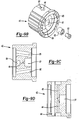
- modified direct current plasma apparatus 10 generally comprises a housing 12 having a cathode 14 (which is negatively charged) extending there through and an anode 16 (which is positively charged) proximally disposed relative to cathode 14 for electrical communication therewith.
- An annular channel 18 extends about cathode 14 and generally between cathode 14 and anode 16.
- Annular channel 18 fluidly communicates a plasma gas 20 as a gaseous inflow from a source (not shown) to a position at least adjacent a tip 22 of cathode 14.
- An electrical arc is established and extends between cathode 14 and anode 16 in a conventional manner.
- the electrical arc ionizes plasma gas 20 to define a plasma jet 24 downstream of cathode 14.
- a precursor material 26, having a composition of desired particles and/or other material, is introduced into at least one of plasma gas 20 and/or plasma jet 24, as will be discussed in detail herein.
- precursor material 26 can be introduced into plasma gas 20 and/or plasma jet 24 from a position generally axially aligned with cathode 14.
- the powders (solid) or droplets (liquid) or gases within precursor 26 are then entrained into the hot plasmas jet 24 and travel with it, eventually forming the desired material, melting and being deposited on a desired target.
- precursor 26 can comprise a plurality of nanoparticles.
- precursor 26 can be a powder of micrometer sized particles of different compounds, a solution of multiple chemicals, a suspension of micrometer or nanometer sized particles of different compounds in a matrix, or a suspension of micrometer or nanometer sized particles within a matrix of solution of multiple chemicals or a gaseous mixture. When treated in the plasma jet, the precursor results into the desired material.
- axial injection of precursor 26 into plasma gas 20 upstream of a tip 28 of cathode 14 can significantly improve the coating achieved following a modified DC plasma process.
- FIG. 10a a typical plasma arc 100 is illustrated originating from a tip 102 of a solid cathode 104.
- the arc root moves to the periphery of the precursor outlet 103 (as seen in FIG. 10b ), which increases the localized temperature about the precursor outlet 103.
- This increased localized temperature cause precursor flowing from the precursor outlet 103 to immediately interact with hot outlet 103, causing the particles or droplets within the precursor to melt and immediately collect at the rim of the precursor outlet 103. Accelerated deposition of the particles or droplets at the precursor outlet 103 leads to premature clogging of the precursor outlet 103 and reduced operational life of the cathode 104.
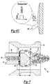
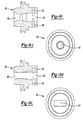
- the present teachings provide a cathode 14 having a plurality of precursor outlet lines 30 radially extending outwardly from a central line 32 extending axially along cathode 14.
- Each of the plurality of precursor outlet lines 30 terminated at an exposed opening 34 along a tapered sidewall portion 36 of cathode 14.
- the exposed openings 34 are disposed at a location upstream a distance "a" from the arc root 38. In this way, the arc root 38, being sufficiently downstream of openings 34, is not disturbed nor drawn to openings 34, thereby maintaining a suitable localized temperature at openings 34 to prevent premature heating, melting, and deposition of particles or droplets contained in the precursor at or near openings 34.
- Cathode 14, having the radially extending precursor outlet lines 30 ensures atomization of the liquid precursor stream.
- the perforated design further ensured stable gun voltage as well as improved cathode life.
- smaller, nano-sized particles contained in precursor 26 are more likely to be properly entrained in the flow of plasma gas 20 and, thus, are less likely to become deposited on cathode 14 or anode 16. Accordingly, smaller particles can be reliably and effectively synthesized/treated and deposited on a target without negatively affecting the useful life of cathode 14.
- the present teachings provide a cathode 14' having a centrally disposed precursor line 32' extending axially along cathode 14' and terminating at an exposed opening.
- Precursor line 32' receives and carries the precursor 26 to exposed opening.
- precursor one 120 and precursor two 26 can independently be fed enabling functionally gradient coating deposition.
- the particle size, phase and density control as well as the efficiency can thus be substantially improved by this axial feeding of the liquid precursor.
- various nanomaterials such as HAP/TiO2 composite, Nb/TaC composite, YSZ and V2O5, have been successfully synthesized for high temperature, energy and biomedical applications.
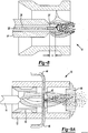
- direct current plasma apparatus 10 can comprise injection of a liquid-based precursor 26 downstream of anode 16. Specifically, using this approach, liquid precursor can be efficiently atomized into droplets inside direct current plasma apparatus 10. This capability has enabled the synthesis of many nanostructured materials resulting in improvements in terms of process control and coating quality.
- direct current plasma apparatus 10 can comprise an axial atomizer assembly 42 having a liquid precursor input 44 and a gas input 46 collectively joined to introduce liquid droplets of precursor 26 at a position downstream of anode 16 and upstream of a water-cooled nozzle 48.
- FIG. 9b illustrates the subcomponents of the atomizer assembly 42. In some embodiments, it can comprise precursor input 44, gas input 46 (See FIG. 9d ), an atomizer housing 61 , an atomizing body 62, an atomizer cap 63, water cooling input 64 and two plasma paths 65.
- FIGS. 9c and 9d illustrate cross sectional views of the atomizer assembly.
- FIG. 9c and 9d illustrate cross sectional views of the atomizer assembly.
- FIGS. 9e through 9h show the cross section of the atomizing body 62 consisting of precursor input 44 and gas inputs 46 and a droplet outlet 66. Different embodiments of the atomizing body 62, 62', 62", and 62"' are shown in FIGS. 9e through 9h .
- Atomized precursor droplets undergo secondary atomization by the plasma jet 24 emerging through plasma paths 65 resulting in fine droplets for material synthesis and deposition on a substrate or target.
- the precursor can be simply gaseous in nature.
- the exit nozzle 48 comprises of plasma inlet 66, plasma outlet 67 and gaseous precursor inputs 68.
- the gaseous precursor input 68 can introduce gases such as acetylene to coat or dope the molten particles with a desired material prior to deposition. This particular approach is beneficial to battery manufacturing where carbon doping is required for enhancing the conductivity.
- the plasma outlet 67 can assume different cross sectional profiles such as cylindrical, elliptical and rectangular.
- FIGS. 9i and 9j illustrate the side and front views of a cylindrical nozzle.
- FIGS. 9k and 9l illustrate the views of rectangular profile. Such renditions are beneficial to control the particle size distribution in the atomized droplets to enhance their synthesis characteristics.
- This design ensured the entrainment of all the liquid droplets in the plasma jet 24 leading to higher deposition efficiency and uniform particulate characteristics. Further, this design also enables embedment of nanoparticles into a bulk matrix resulting in a composite coating.
- the matrix material and the liquid precursor are independently fed enabling functionally gradient coating deposition.
- various nanomaterials such as TiO2, YSZ, V2O5, LiFePO4, LiCoO2, LiCoNiMnO6, Eu-doped SrAl2O4, Dy-doped SrAl2O4, CdSe, CdS, ZnO, InO2 and InSnO2 have been successfully synthesized for high temperature, energy and biomedical applications.
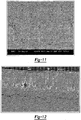
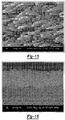
- Typical plasma coatings made using powder or liquid precursors have a particulate structure as illustrated in FIG. 11 .
- the inter-particulate boundaries contain impurities and voids which are detrimental to properties of these coatings.
- researchers have attempted to use a laser beam to remelt and densify coatings following complete deposition and formation of the article.
- a laser beam has a limited penetration depth and, thus, thick coatings cannot be adequately treated.
- post deposition treatment typically leads to defects and cracks, especially in ceramic materials as shown in FIG. 12 .
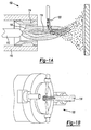
- direct current plasma apparatus 10 is provided with a laser beam that is capable of treating the coating, layer by layer, nearly simultaneously as the layers are deposited by plasma jet 24 on the substrate. That is, laser radiation energy output from a laser source 50 can be directed to coating deposited on a substrate using the methods set forth herein.
- each thinly-deposited layer on a substrate can be immediately modified, tailored, or otherwise processed by the laser source 50 in a simple and simultaneous manner.
- laser source 50 is disposed adjacent or integrally formed with modified direct current plasma source 10 to output laser radiation energy upon the substrate being processed.
- the laser beam can assume either a Gaussian energy distribution 50' or rectangular 50" (multimode) energy distribution illustrated in FIGS. 6b and 6c . Further, the laser beam can be delivered via an optical fiber or an optical train or their combinations. In some embodiment of the present teachings, multiple laser beams with same or dissimilar characteristics (wave length, beam diameter or energy density) can be utilized to perform pretreatment or post treatment of the aforementioned coatings.
- the direct current plasma apparatus 10 can be effectively used for the creation of solid oxide fuel cells.
- the anode, electrolyte and the cathode layers are deposited by the direct current plasma apparatus 10 using either solid precursor powders, liquid precursors, gaseous precursors, or a combination thereof.
- In-situ densification of the layers is achieved with the laser source 50 by remelting the plasma deposited material, especially in the electrolyte layer.
- direct current plasma apparatus 10 can further comprise the teachings set forth herein relating to cathode and anode variations.
- Li-ion battery cells typically comprise an anode and a cathode for battery operation.
- Different materials are being tested for both cathode and anode in the industry. In general, these materials are complex compounds, need to have good conductivity (carbon coated particulates), and should be made of nanoparticulates for maximized performance.
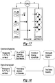
- the industrial battery manufacturing techniques of the present teachings comprise a multi-step material synthesis and electrode assembly process. In our approach we employ the plasma and laser technology developed above to directly synthesize the electrodes reducing the number of steps, time, and cost.
- liquid precursors solutions, and suspensions in solutions
- direct current plasma system 10 to synthesize the desired material chemistry and structure and directly form the cathodic film in a unique manner.
- the process is generally set forth in FIG. 18 , wherein processing steps in the prior art are eliminated.
- laser source 50 can be employed to densify or further treat the layers or film, if desired.
- nanoengineered electrode compounds in powder form to be used in the current industrial processes. Further, in some embodiment of the current teachings one can also achieve thermal treatment of these powders in flight using the direct current plasma apparatus 10.
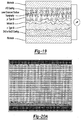
- silicon in nano-particulate form or ultrafine pillar form (as shown in FIG. 15 ), is a good anode material.
- This material can be formed in the shape of pillars through various processes. Specifically, such pillars can be formed by treating a silicon wafer using a laser.
- using a silicon wafer to manufacture an anode is not a cost effective approach.
- the ability to deposit silicon coating by direct current plasma apparatus 10 on a metal conductor and subsequent treatment using laser source 50 to make nanostructured surfaces permits large area anodes to be produced in a simple and cost effective manner.
- many other compounds, such as transition metal compounds can be formed which have wide ranging applications, such as sensors, reactors, and the like.
- a gaseous precursor containing silicon can be used to deposit nanoparticles onto a desired target to manufacture nanoparticulate based electrodes. Further, these nanoparticulates can be coated with carbon using appropriate gaseous precursors, such as acetylene, using the nozzle input 68.
- Achieving a viable product for harnessing solar energy requires a balancing between creating efficient cells and at the same time reducing the manufacturing cost. While conventional polycrystalline cells are efficient, thin film amorphous solar cells have proven to be cost effective on the basis of overall price per watt. Polycrystalline cells are made by ingot casting and slicing the wafers. Amorphous thin film cells are made with chemical Vapor Deposition process.
- a unique process using direct current plasma apparatus 10 uses benign precursors (powders (Si), liquids (ZnCl 2 , InCl 3 and SnCl 4 ), and gaseous (Silane) precursors) to achieve polycrystalline efficiency at thin film manufacturing cost.
- the proposed cells consist of multi-junction Si films with efficient back reflector and enhanced surface absorber (see FIG. 19 ). All the layers are deposited using direct current plasma apparatus 10 and microstructurally engineered using laser beam 50.
- the principles of the present teachings are capable of achieving wafer grade efficiency at thin film manufacturing cost.
- the plasma deposition process (deposition rate ⁇ m/sec) of the present teachings is much faster than thin film deposition (PECVD, deposition rate nm/min) processes.
- PECVD thin film deposition
- Fig. 5 the inherent inter-droplet boundaries of conventional plasma sprayed deposits make them unsuitable for photovoltaic applications.
- wafer grade crystallinity can be achieved at a rapid rate.
- the deposition process of the present teachings retains many of the attractive features of thin film technology i.e., multi-junction capability (see FIGS. 19 and 20 ) and low manufacturing cost.
- in-situ cell surface patterning using laser source 50 can enhance light absorption (see FIG. 15 ), which could not previously be achieved using other techniques, such as etching.
- a multi-junction crystalline solar cell can be achieved which was not possible by the prior art of ingot casting.
- the method can comprise:
- Solid Oxide Fuel Cell (SOFC) manufacturing presents significant challenges due to the requirement of differential densities in the successive layers as well as thermal shock resistance.
- the anode and cathode layer of the SOFC need to be porous while the electrolyte layer needs to reach full density (see FIG. 21 ).
- SOFCs are produced using wet ceramic techniques and subsequent lengthy sintering processes.
- plasma spray deposition is also used to deposit the anode, electrolyte and the cathode followed by sintering for densification. While sintering reduces the porosity level in the electrolyte, it also leads to unwanted densification of the cathode and anode layer.
- the direct current plasma apparatus 10 using laser source 50 can provide unique advantage to engineer the microstructure as needed
- each layer of the SOFC can be deposited and custom tailored using laser source 50 to achieve a desired densification.
- Such a methodology can improve the deposition rate considerably in comparison to deposition using precursors comprised of suspended YSZ particles in a carrier liquid.
- Such coatings have a wide variety of applications in the aerospace and medical industries.
Landscapes
- Physics & Mathematics (AREA)
- Engineering & Computer Science (AREA)
- Plasma & Fusion (AREA)
- Spectroscopy & Molecular Physics (AREA)
- General Engineering & Computer Science (AREA)
- High Energy & Nuclear Physics (AREA)
- Optics & Photonics (AREA)
- Geometry (AREA)
- Coating By Spraying Or Casting (AREA)
- Chemical Vapour Deposition (AREA)
- Inorganic Compounds Of Heavy Metals (AREA)
Applications Claiming Priority (4)
| Application Number | Priority Date | Filing Date | Title |
|---|---|---|---|
| US17457609P | 2009-05-01 | 2009-05-01 | |
| US23386309P | 2009-08-14 | 2009-08-14 | |
| US12/772,342 US8294060B2 (en) | 2009-05-01 | 2010-05-03 | In-situ plasma/laser hybrid scheme |
| PCT/US2010/033383 WO2010127344A2 (en) | 2009-05-01 | 2010-05-03 | In-situ plasma/laser hybrid scheme |
Publications (3)
| Publication Number | Publication Date |
|---|---|
| EP2425685A2 EP2425685A2 (en) | 2012-03-07 |
| EP2425685A4 EP2425685A4 (en) | 2014-11-26 |
| EP2425685B1 true EP2425685B1 (en) | 2016-10-26 |
Family
ID=43032818
Family Applications (1)
| Application Number | Title | Priority Date | Filing Date |
|---|---|---|---|
| EP10770480.1A Active EP2425685B1 (en) | 2009-05-01 | 2010-05-03 | In-situ plasma/laser hybrid scheme |
Country Status (10)
| Country | Link |
|---|---|
| US (1) | US8294060B2 (da) |
| EP (1) | EP2425685B1 (da) |
| KR (1) | KR20120036817A (da) |
| CN (1) | CN102450108B (da) |
| AU (1) | AU2010242747B2 (da) |
| CA (1) | CA2760612A1 (da) |
| DK (1) | DK2425685T3 (da) |
| ES (1) | ES2607704T3 (da) |
| NZ (1) | NZ596174A (da) |
| WO (1) | WO2010127344A2 (da) |
Families Citing this family (33)
| Publication number | Priority date | Publication date | Assignee | Title |
|---|---|---|---|---|
| US9173967B1 (en) | 2007-05-11 | 2015-11-03 | SDCmaterials, Inc. | System for and method of processing soft tissue and skin with fluids using temperature and pressure changes |
| US8507401B1 (en) | 2007-10-15 | 2013-08-13 | SDCmaterials, Inc. | Method and system for forming plug and play metal catalysts |
| KR101770576B1 (ko) * | 2009-12-04 | 2017-08-23 | 더 리젠츠 오브 더 유니버시티 오브 미시건 | 동축 레이저 보조형 콜드 스프레이 노즐 |
| US8803025B2 (en) * | 2009-12-15 | 2014-08-12 | SDCmaterials, Inc. | Non-plugging D.C. plasma gun |
| US8652992B2 (en) | 2009-12-15 | 2014-02-18 | SDCmaterials, Inc. | Pinning and affixing nano-active material |
| US9039916B1 (en) | 2009-12-15 | 2015-05-26 | SDCmaterials, Inc. | In situ oxide removal, dispersal and drying for copper copper-oxide |
| US9149797B2 (en) | 2009-12-15 | 2015-10-06 | SDCmaterials, Inc. | Catalyst production method and system |
| US8557727B2 (en) | 2009-12-15 | 2013-10-15 | SDCmaterials, Inc. | Method of forming a catalyst with inhibited mobility of nano-active material |
| US9126191B2 (en) | 2009-12-15 | 2015-09-08 | SDCmaterials, Inc. | Advanced catalysts for automotive applications |
| US8669202B2 (en) | 2011-02-23 | 2014-03-11 | SDCmaterials, Inc. | Wet chemical and plasma methods of forming stable PtPd catalysts |
| US9605376B2 (en) * | 2011-06-28 | 2017-03-28 | Mtix Ltd. | Treating materials with combined energy sources |
| US9309619B2 (en) * | 2011-06-28 | 2016-04-12 | Mtix Ltd. | Method and apparatus for surface treatment of materials utilizing multiple combined energy sources |
| BR112014003781A2 (pt) | 2011-08-19 | 2017-03-21 | Sdcmaterials Inc | substratos revestidos para uso em catalisadores e conversores catalíticos e métodos para revestir substratos com composições de revestimento por imersão |
| ZA201202480B (en) * | 2011-10-17 | 2012-11-28 | Int Advanced Res Centre For Power Metallurgy And New Mat (Arci) Dept Of Science And Tech Govt Of Ind | An improved hybrid methodology for producing composite,multi-layered and graded coatings by plasma spraying utitilizing powder and solution precurrsor feedstock |
| US9156025B2 (en) | 2012-11-21 | 2015-10-13 | SDCmaterials, Inc. | Three-way catalytic converter using nanoparticles |
| US9511352B2 (en) | 2012-11-21 | 2016-12-06 | SDCmaterials, Inc. | Three-way catalytic converter using nanoparticles |
| US9586179B2 (en) | 2013-07-25 | 2017-03-07 | SDCmaterials, Inc. | Washcoats and coated substrates for catalytic converters and methods of making and using same |
| MX2016004759A (es) | 2013-10-22 | 2016-07-26 | Sdcmaterials Inc | Composiciones para trampas de oxidos de nitrogeno (nox) pobres. |
| CN106061600A (zh) | 2013-10-22 | 2016-10-26 | Sdc材料公司 | 用于重型柴油机的催化剂设计 |
| US9687811B2 (en) | 2014-03-21 | 2017-06-27 | SDCmaterials, Inc. | Compositions for passive NOx adsorption (PNA) systems and methods of making and using same |
| US10730798B2 (en) * | 2014-05-07 | 2020-08-04 | Applied Materials, Inc. | Slurry plasma spray of plasma resistant ceramic coating |
| GB201409692D0 (en) * | 2014-05-31 | 2014-07-16 | Element Six Gmbh | Thermal spray assembly and method for using it |
| DE102014219275A1 (de) * | 2014-09-24 | 2016-03-24 | Siemens Aktiengesellschaft | Zündung von Flammen eines elektropositiven Metalls durch Plasmatisierung des Reaktionsgases |
| CN105376921A (zh) * | 2015-12-11 | 2016-03-02 | 武汉科技大学 | 一种等离子加工用的内腔供粉钨针 |
| AU2016384478B2 (en) * | 2016-01-05 | 2020-10-01 | Helix Co., Ltd. | Vortex water flow generator, water plasma generating device, decomposition treatment device, vehicle equipped with decomposition treatment device, and decomposition treatment method |
| US20170291856A1 (en) * | 2016-04-06 | 2017-10-12 | Applied Materials, Inc. | Solution precursor plasma spray of ceramic coating for semiconductor chamber applications |
| US20220361313A1 (en) * | 2019-09-30 | 2022-11-10 | Tocalo Co., Ltd. | Low pressure plasma spraying |
| CN111100979B (zh) * | 2019-12-26 | 2021-06-22 | 上海联影医疗科技股份有限公司 | X射线管阳极靶盘的激光冲击强化方法 |
| CN113049256B (zh) * | 2019-12-27 | 2025-03-28 | 北航(四川)西部国际创新港科技有限公司 | 一种模拟航空发动机服役环境的高温高速焰流发生装置 |
| AU2022206483A1 (en) | 2021-01-11 | 2023-08-31 | 6K Inc. | Methods and systems for reclamation of li-ion cathode materials using microwave plasma processing |
| JP2024506474A (ja) * | 2021-01-19 | 2024-02-14 | シックスケー インコーポレイテッド | マイクロ波プラズマ処理を用いた単結晶正極材料 |
| US12525599B2 (en) | 2021-12-21 | 2026-01-13 | Our Next Energy, Inc. | Manufacturing battery electrodes |
| CN115537737B (zh) * | 2022-10-13 | 2023-11-17 | 西南交通大学 | 一种薄涂层的制备方法及系统 |
Family Cites Families (17)
| Publication number | Priority date | Publication date | Assignee | Title |
|---|---|---|---|---|
| US3729611A (en) * | 1968-04-16 | 1973-04-24 | Centrul De Sudura Si Incercari | Plasma generator |
| US4127760A (en) * | 1975-06-09 | 1978-11-28 | Geotel, Inc. | Electrical plasma jet torch and electrode therefor |
| CN1028772C (zh) * | 1987-04-03 | 1995-06-07 | 富士通株式会社 | 汽相淀积金刚石的方法 |
| US5296667A (en) * | 1990-08-31 | 1994-03-22 | Flame-Spray Industries, Inc. | High velocity electric-arc spray apparatus and method of forming materials |
| CA2084281C (fr) * | 1992-12-01 | 1999-07-06 | Roberto Nunes Szente | Torche a plasma pour deposition avec injection centrale |
| JPH06272012A (ja) * | 1993-03-19 | 1994-09-27 | Hirofumi Shimura | レーザ・プラズマハイブリッド溶射による高機能性被膜の作製方法 |
| JPH07316774A (ja) * | 1994-03-31 | 1995-12-05 | Mitsubishi Heavy Ind Ltd | 低圧プラズマ溶射方法 |
| JPH08243756A (ja) * | 1995-03-03 | 1996-09-24 | Mitsubishi Materials Corp | プラズマ肉盛用溶接トーチ及び肉盛溶接方法 |
| CN1217787C (zh) * | 2000-06-30 | 2005-09-07 | 微涂技术股份有限公司 | 聚合物涂层 |
| JP2002145615A (ja) | 2000-11-08 | 2002-05-22 | Japan Science & Technology Corp | TiO2薄膜及び色素増感太陽電池用作用電極の作製方法 |
| US20020172871A1 (en) * | 2001-05-18 | 2002-11-21 | Trans Ionics Corporation | Thin film composite electrolytes, sodium-sulfur cells including same, processes of making same, and vehicles including same |
| CN1204979C (zh) * | 2001-11-30 | 2005-06-08 | 中国科学院力学研究所 | 层流等离子体喷涂装置及方法 |
| US20070264564A1 (en) * | 2006-03-16 | 2007-11-15 | Infinite Power Solutions, Inc. | Thin film battery on an integrated circuit or circuit board and method thereof |
| US7750265B2 (en) * | 2004-11-24 | 2010-07-06 | Vladimir Belashchenko | Multi-electrode plasma system and method for thermal spraying |
| US7887923B2 (en) * | 2005-03-09 | 2011-02-15 | Evonik Degussa Gmbh | Plasma-sprayed layers of aluminium oxide |
| US20100034979A1 (en) * | 2006-06-28 | 2010-02-11 | Fundacion Inasmet | Thermal spraying method and device |
| ES2534215T3 (es) * | 2006-08-30 | 2015-04-20 | Oerlikon Metco Ag, Wohlen | Dispositivo de pulverización de plasma y un método para la introducción de un precursor líquido en un sistema de gas de plasma |
-
2010
- 2010-05-03 WO PCT/US2010/033383 patent/WO2010127344A2/en not_active Ceased
- 2010-05-03 US US12/772,342 patent/US8294060B2/en active Active
- 2010-05-03 CA CA2760612A patent/CA2760612A1/en not_active Abandoned
- 2010-05-03 CN CN201080024186.4A patent/CN102450108B/zh active Active
- 2010-05-03 KR KR1020117028861A patent/KR20120036817A/ko not_active Ceased
- 2010-05-03 EP EP10770480.1A patent/EP2425685B1/en active Active
- 2010-05-03 NZ NZ596174A patent/NZ596174A/xx unknown
- 2010-05-03 ES ES10770480.1T patent/ES2607704T3/es active Active
- 2010-05-03 AU AU2010242747A patent/AU2010242747B2/en active Active
- 2010-05-03 DK DK10770480.1T patent/DK2425685T3/en active
Also Published As
| Publication number | Publication date |
|---|---|
| AU2010242747A1 (en) | 2011-11-24 |
| US20100320176A1 (en) | 2010-12-23 |
| EP2425685A4 (en) | 2014-11-26 |
| WO2010127344A3 (en) | 2011-01-13 |
| EP2425685A2 (en) | 2012-03-07 |
| KR20120036817A (ko) | 2012-04-18 |
| US8294060B2 (en) | 2012-10-23 |
| CN102450108B (zh) | 2014-08-20 |
| CN102450108A (zh) | 2012-05-09 |
| CA2760612A1 (en) | 2010-11-04 |
| ES2607704T3 (es) | 2017-04-03 |
| AU2010242747B2 (en) | 2014-03-20 |
| WO2010127344A2 (en) | 2010-11-04 |
| NZ596174A (en) | 2013-07-26 |
| DK2425685T3 (en) | 2017-01-30 |
Similar Documents
| Publication | Publication Date | Title |
|---|---|---|
| EP2425685B1 (en) | In-situ plasma/laser hybrid scheme | |
| US11534833B2 (en) | Method for laser-assisted manufacturing | |
| Mittal et al. | Suspension and solution precursor plasma and HVOF spray: A review | |
| Fauchais et al. | Suspension and solution plasma spraying of finely structured layers: potential application to SOFCs | |
| EP1880034B1 (en) | Method and apparatus for fine particle liquid suspension feed for thermal spray system and coatings formed therefrom | |
| Jaworek | Electrospray droplet sources for thin film deposition | |
| US20100323118A1 (en) | Direct thermal spray synthesis of li ion battery components | |
| Guild et al. | Perspectives of spray pyrolysis for facile synthesis of catalysts and thin films: An introduction and summary of recent directions | |
| US20020106452A1 (en) | Material fabrication | |
| CN104919075A (zh) | 制造基于固体的薄膜电池的至少一层的方法、其等离子体粉末喷枪和基于固体的薄膜电池 | |
| CN106415888A (zh) | 大气等离子体应用的将金属涂覆到锂二次电池电极材料上 | |
| JP7536839B2 (ja) | 電極製造用の金属及び活性電池材料を含む粒子の製造方法 | |
| CN115003624A (zh) | 可再充电电池用的通过电弧炉的纳米硅颗粒/线生产 | |
| Aghasibeig et al. | Fabrication of nickel electrode coatings by combination of atmospheric and suspension plasma spray processes | |
| Yu et al. | Development of photocatalytic and electrocatalytic coatings via thermal spraying for environmental and energy storage applications: a short review | |
| WO2021149737A1 (ja) | 2次電池の製造方法または2次電池 | |
| Nomura et al. | Fabrication of YSZ electrolyte using electrostatic spray deposition (ESD): I–a comprehensive parametric study | |
| WO2018134484A1 (en) | Method for the manufacture of anode materials for li ion batteries by utilising short-term laser pulses | |
| MX2011011550A (es) | Esquema hibrido in-situ de plasma/laser. | |
| de Souzaa et al. | Plasma technology for nanostructures | |
| Tsui et al. | Aerosol Jet Deposition for Structured Materials | |
| de Souza et al. | Plasma technology for nanostructures | |
| Waldbillig et al. | Suspension plasma spraying of solid oxide fuel cell electrolytes | |
| Ando et al. | Rapid deposition of photocatalytic oxide film by liquid feedstock injection TPCVD in open air | |
| HK40071821A (en) | Nano-silicon particles/wire production by arc furnace for rechargeable batteries |
Legal Events
| Date | Code | Title | Description |
|---|---|---|---|
| PUAI | Public reference made under article 153(3) epc to a published international application that has entered the european phase |
Free format text: ORIGINAL CODE: 0009012 |
|
| 17P | Request for examination filed |
Effective date: 20111122 |
|
| AK | Designated contracting states |
Kind code of ref document: A2 Designated state(s): AL AT BE BG CH CY CZ DE DK EE ES FI FR GB GR HR HU IE IS IT LI LT LU LV MC MK MT NL NO PL PT RO SE SI SK SM TR |
|
| DAX | Request for extension of the european patent (deleted) | ||
| A4 | Supplementary search report drawn up and despatched |
Effective date: 20141027 |
|
| RIC1 | Information provided on ipc code assigned before grant |
Ipc: G21K 5/00 20060101ALI20141021BHEP Ipc: H05G 2/00 20060101ALI20141021BHEP Ipc: H05H 1/42 20060101ALI20141021BHEP Ipc: H05H 1/24 20060101AFI20141021BHEP |
|
| GRAP | Despatch of communication of intention to grant a patent |
Free format text: ORIGINAL CODE: EPIDOSNIGR1 |
|
| INTG | Intention to grant announced |
Effective date: 20160506 |
|
| GRAS | Grant fee paid |
Free format text: ORIGINAL CODE: EPIDOSNIGR3 |
|
| GRAA | (expected) grant |
Free format text: ORIGINAL CODE: 0009210 |
|
| AK | Designated contracting states |
Kind code of ref document: B1 Designated state(s): AL AT BE BG CH CY CZ DE DK EE ES FI FR GB GR HR HU IE IS IT LI LT LU LV MC MK MT NL NO PL PT RO SE SI SK SM TR |
|
| REG | Reference to a national code |
Ref country code: GB Ref legal event code: FG4D |
|
| REG | Reference to a national code |
Ref country code: CH Ref legal event code: EP |
|
| REG | Reference to a national code |
Ref country code: AT Ref legal event code: REF Ref document number: 840806 Country of ref document: AT Kind code of ref document: T Effective date: 20161115 |
|
| REG | Reference to a national code |
Ref country code: IE Ref legal event code: FG4D |
|
| REG | Reference to a national code |
Ref country code: DE Ref legal event code: R096 Ref document number: 602010037493 Country of ref document: DE |
|
| REG | Reference to a national code |
Ref country code: CH Ref legal event code: NV Representative=s name: TROESCH SCHEIDEGGER WERNER AG, CH |
|
| REG | Reference to a national code |
Ref country code: NL Ref legal event code: FP |
|
| REG | Reference to a national code |
Ref country code: DK Ref legal event code: T3 Effective date: 20170127 |
|
| REG | Reference to a national code |
Ref country code: SE Ref legal event code: TRGR |
|
| REG | Reference to a national code |
Ref country code: LT Ref legal event code: MG4D |
|
| PG25 | Lapsed in a contracting state [announced via postgrant information from national office to epo] |
Ref country code: LV Free format text: LAPSE BECAUSE OF FAILURE TO SUBMIT A TRANSLATION OF THE DESCRIPTION OR TO PAY THE FEE WITHIN THE PRESCRIBED TIME-LIMIT Effective date: 20161026 |
|
| REG | Reference to a national code |
Ref country code: NO Ref legal event code: T2 Effective date: 20161026 |
|
| REG | Reference to a national code |
Ref country code: AT Ref legal event code: MK05 Ref document number: 840806 Country of ref document: AT Kind code of ref document: T Effective date: 20161026 |
|
| PG25 | Lapsed in a contracting state [announced via postgrant information from national office to epo] |
Ref country code: LT Free format text: LAPSE BECAUSE OF FAILURE TO SUBMIT A TRANSLATION OF THE DESCRIPTION OR TO PAY THE FEE WITHIN THE PRESCRIBED TIME-LIMIT Effective date: 20161026 Ref country code: GR Free format text: LAPSE BECAUSE OF FAILURE TO SUBMIT A TRANSLATION OF THE DESCRIPTION OR TO PAY THE FEE WITHIN THE PRESCRIBED TIME-LIMIT Effective date: 20170127 |
|
| REG | Reference to a national code |
Ref country code: FR Ref legal event code: PLFP Year of fee payment: 8 |
|
| PG25 | Lapsed in a contracting state [announced via postgrant information from national office to epo] |
Ref country code: PT Free format text: LAPSE BECAUSE OF FAILURE TO SUBMIT A TRANSLATION OF THE DESCRIPTION OR TO PAY THE FEE WITHIN THE PRESCRIBED TIME-LIMIT Effective date: 20170227 Ref country code: IS Free format text: LAPSE BECAUSE OF FAILURE TO SUBMIT A TRANSLATION OF THE DESCRIPTION OR TO PAY THE FEE WITHIN THE PRESCRIBED TIME-LIMIT Effective date: 20170226 Ref country code: FI Free format text: LAPSE BECAUSE OF FAILURE TO SUBMIT A TRANSLATION OF THE DESCRIPTION OR TO PAY THE FEE WITHIN THE PRESCRIBED TIME-LIMIT Effective date: 20161026 Ref country code: HR Free format text: LAPSE BECAUSE OF FAILURE TO SUBMIT A TRANSLATION OF THE DESCRIPTION OR TO PAY THE FEE WITHIN THE PRESCRIBED TIME-LIMIT Effective date: 20161026 Ref country code: BE Free format text: LAPSE BECAUSE OF FAILURE TO SUBMIT A TRANSLATION OF THE DESCRIPTION OR TO PAY THE FEE WITHIN THE PRESCRIBED TIME-LIMIT Effective date: 20161026 Ref country code: AT Free format text: LAPSE BECAUSE OF FAILURE TO SUBMIT A TRANSLATION OF THE DESCRIPTION OR TO PAY THE FEE WITHIN THE PRESCRIBED TIME-LIMIT Effective date: 20161026 Ref country code: PL Free format text: LAPSE BECAUSE OF FAILURE TO SUBMIT A TRANSLATION OF THE DESCRIPTION OR TO PAY THE FEE WITHIN THE PRESCRIBED TIME-LIMIT Effective date: 20161026 |
|
| REG | Reference to a national code |
Ref country code: DE Ref legal event code: R097 Ref document number: 602010037493 Country of ref document: DE |
|
| PG25 | Lapsed in a contracting state [announced via postgrant information from national office to epo] |
Ref country code: SK Free format text: LAPSE BECAUSE OF FAILURE TO SUBMIT A TRANSLATION OF THE DESCRIPTION OR TO PAY THE FEE WITHIN THE PRESCRIBED TIME-LIMIT Effective date: 20161026 Ref country code: RO Free format text: LAPSE BECAUSE OF FAILURE TO SUBMIT A TRANSLATION OF THE DESCRIPTION OR TO PAY THE FEE WITHIN THE PRESCRIBED TIME-LIMIT Effective date: 20161026 Ref country code: EE Free format text: LAPSE BECAUSE OF FAILURE TO SUBMIT A TRANSLATION OF THE DESCRIPTION OR TO PAY THE FEE WITHIN THE PRESCRIBED TIME-LIMIT Effective date: 20161026 |
|
| PG25 | Lapsed in a contracting state [announced via postgrant information from national office to epo] |
Ref country code: SM Free format text: LAPSE BECAUSE OF FAILURE TO SUBMIT A TRANSLATION OF THE DESCRIPTION OR TO PAY THE FEE WITHIN THE PRESCRIBED TIME-LIMIT Effective date: 20161026 Ref country code: BG Free format text: LAPSE BECAUSE OF FAILURE TO SUBMIT A TRANSLATION OF THE DESCRIPTION OR TO PAY THE FEE WITHIN THE PRESCRIBED TIME-LIMIT Effective date: 20170126 Ref country code: LU Free format text: LAPSE BECAUSE OF NON-PAYMENT OF DUE FEES Effective date: 20170531 |
|
| PLBE | No opposition filed within time limit |
Free format text: ORIGINAL CODE: 0009261 |
|
| STAA | Information on the status of an ep patent application or granted ep patent |
Free format text: STATUS: NO OPPOSITION FILED WITHIN TIME LIMIT |
|
| 26N | No opposition filed |
Effective date: 20170727 |
|
| PG25 | Lapsed in a contracting state [announced via postgrant information from national office to epo] |
Ref country code: SI Free format text: LAPSE BECAUSE OF FAILURE TO SUBMIT A TRANSLATION OF THE DESCRIPTION OR TO PAY THE FEE WITHIN THE PRESCRIBED TIME-LIMIT Effective date: 20161026 |
|
| PG25 | Lapsed in a contracting state [announced via postgrant information from national office to epo] |
Ref country code: MC Free format text: LAPSE BECAUSE OF FAILURE TO SUBMIT A TRANSLATION OF THE DESCRIPTION OR TO PAY THE FEE WITHIN THE PRESCRIBED TIME-LIMIT Effective date: 20161026 |
|
| PG25 | Lapsed in a contracting state [announced via postgrant information from national office to epo] |
Ref country code: LU Free format text: LAPSE BECAUSE OF NON-PAYMENT OF DUE FEES Effective date: 20170503 |
|
| REG | Reference to a national code |
Ref country code: FR Ref legal event code: PLFP Year of fee payment: 9 |
|
| PG25 | Lapsed in a contracting state [announced via postgrant information from national office to epo] |
Ref country code: MT Free format text: LAPSE BECAUSE OF NON-PAYMENT OF DUE FEES Effective date: 20170503 |
|
| PG25 | Lapsed in a contracting state [announced via postgrant information from national office to epo] |
Ref country code: HU Free format text: LAPSE BECAUSE OF FAILURE TO SUBMIT A TRANSLATION OF THE DESCRIPTION OR TO PAY THE FEE WITHIN THE PRESCRIBED TIME-LIMIT; INVALID AB INITIO Effective date: 20100503 |
|
| PG25 | Lapsed in a contracting state [announced via postgrant information from national office to epo] |
Ref country code: CY Free format text: LAPSE BECAUSE OF NON-PAYMENT OF DUE FEES Effective date: 20161026 |
|
| PG25 | Lapsed in a contracting state [announced via postgrant information from national office to epo] |
Ref country code: MK Free format text: LAPSE BECAUSE OF FAILURE TO SUBMIT A TRANSLATION OF THE DESCRIPTION OR TO PAY THE FEE WITHIN THE PRESCRIBED TIME-LIMIT Effective date: 20161026 |
|
| PG25 | Lapsed in a contracting state [announced via postgrant information from national office to epo] |
Ref country code: TR Free format text: LAPSE BECAUSE OF FAILURE TO SUBMIT A TRANSLATION OF THE DESCRIPTION OR TO PAY THE FEE WITHIN THE PRESCRIBED TIME-LIMIT Effective date: 20161026 |
|
| PG25 | Lapsed in a contracting state [announced via postgrant information from national office to epo] |
Ref country code: AL Free format text: LAPSE BECAUSE OF FAILURE TO SUBMIT A TRANSLATION OF THE DESCRIPTION OR TO PAY THE FEE WITHIN THE PRESCRIBED TIME-LIMIT Effective date: 20161026 |
|
| P01 | Opt-out of the competence of the unified patent court (upc) registered |
Effective date: 20230505 |
|
| PGFP | Annual fee paid to national office [announced via postgrant information from national office to epo] |
Ref country code: NL Payment date: 20250522 Year of fee payment: 16 |
|
| PGFP | Annual fee paid to national office [announced via postgrant information from national office to epo] |
Ref country code: DE Payment date: 20250519 Year of fee payment: 16 |
|
| PGFP | Annual fee paid to national office [announced via postgrant information from national office to epo] |
Ref country code: DK Payment date: 20250521 Year of fee payment: 16 Ref country code: ES Payment date: 20250616 Year of fee payment: 16 |
|
| PGFP | Annual fee paid to national office [announced via postgrant information from national office to epo] |
Ref country code: NO Payment date: 20250520 Year of fee payment: 16 |
|
| PGFP | Annual fee paid to national office [announced via postgrant information from national office to epo] |
Ref country code: IT Payment date: 20250530 Year of fee payment: 16 |
|
| PGFP | Annual fee paid to national office [announced via postgrant information from national office to epo] |
Ref country code: FR Payment date: 20250521 Year of fee payment: 16 |
|
| PGFP | Annual fee paid to national office [announced via postgrant information from national office to epo] |
Ref country code: CH Payment date: 20250601 Year of fee payment: 16 |
|
| PGFP | Annual fee paid to national office [announced via postgrant information from national office to epo] |
Ref country code: CZ Payment date: 20250417 Year of fee payment: 16 |
|
| PGFP | Annual fee paid to national office [announced via postgrant information from national office to epo] |
Ref country code: IE Payment date: 20250521 Year of fee payment: 16 |
|
| PGFP | Annual fee paid to national office [announced via postgrant information from national office to epo] |
Ref country code: SE Payment date: 20250522 Year of fee payment: 16 |
|
| PGFP | Annual fee paid to national office [announced via postgrant information from national office to epo] |
Ref country code: GB Payment date: 20260326 Year of fee payment: 17 |