EP2425497B1 - Befestigungsvorrichtung zum befestigen eines anschlusssteckers an einem grundgehäuse - Google Patents
Befestigungsvorrichtung zum befestigen eines anschlusssteckers an einem grundgehäuse Download PDFInfo
- Publication number
- EP2425497B1 EP2425497B1 EP10719734.5A EP10719734A EP2425497B1 EP 2425497 B1 EP2425497 B1 EP 2425497B1 EP 10719734 A EP10719734 A EP 10719734A EP 2425497 B1 EP2425497 B1 EP 2425497B1
- Authority
- EP
- European Patent Office
- Prior art keywords
- fastening
- connector
- region
- plug
- housing
- Prior art date
- Legal status (The legal status is an assumption and is not a legal conclusion. Google has not performed a legal analysis and makes no representation as to the accuracy of the status listed.)
- Active
Links
Images


Classifications
-
- H—ELECTRICITY
- H01—ELECTRIC ELEMENTS
- H01R—ELECTRICALLY-CONDUCTIVE CONNECTIONS; STRUCTURAL ASSOCIATIONS OF A PLURALITY OF MUTUALLY-INSULATED ELECTRICAL CONNECTING ELEMENTS; COUPLING DEVICES; CURRENT COLLECTORS
- H01R13/00—Details of coupling devices of the kinds covered by groups H01R12/70 or H01R24/00 - H01R33/00
- H01R13/62—Means for facilitating engagement or disengagement of coupling parts or for holding them in engagement
- H01R13/627—Snap or like fastening
- H01R13/6275—Latching arms not integral with the housing
-
- H—ELECTRICITY
- H01—ELECTRIC ELEMENTS
- H01R—ELECTRICALLY-CONDUCTIVE CONNECTIONS; STRUCTURAL ASSOCIATIONS OF A PLURALITY OF MUTUALLY-INSULATED ELECTRICAL CONNECTING ELEMENTS; COUPLING DEVICES; CURRENT COLLECTORS
- H01R13/00—Details of coupling devices of the kinds covered by groups H01R12/70 or H01R24/00 - H01R33/00
- H01R13/62—Means for facilitating engagement or disengagement of coupling parts or for holding them in engagement
- H01R13/639—Additional means for holding or locking coupling parts together, after engagement, e.g. separate keylock, retainer strap
Definitions
- the invention relates to a fastening device for fastening a connector plug to a base housing by means of a fastening element. Furthermore, the invention relates to a connector assembly with such a fastening device.
- a connector usually has a plug housing consisting of an insulating material with at least one conductor connecting element arranged therein and a plug contact connected to the conductor connecting element.
- the connector may be formed as a screw terminal on which a screw shaft is provided on the connector housing, via which a screw can be inserted into the interior of the connector housing.
- a base housing may be provided, which is usually arranged via solder pins on the circuit board and has a slot for attaching the connector plug.
- Such plug assemblies are mainly used where a contact protection of the connector plug to the circuit board is desired.
- fastening devices which have a fastening means.
- fastening means are usually on the connector and / or on the base housing special receiving elements, for example in the form of openings provided, in which the fastening means in the attached state, ie in the state when the Connector is attached to the base housing, engages.
- This increases on the one hand the design effort of such connector assemblies and also the fasteners are usually so arranged on the connector and the base housing that they are difficult to access for a user and thus cumbersome to operate. Replacing the fasteners is considerably more difficult and is usually possible only with additional tools.
- the EP 2 321 875 A0 is an older post-published document and must be considered for novelty under Article 54 (3) EPC. From the EP 2 321 875 A0 An electrical connector assembly is known.
- the connector assembly has a printed circuit board 204, a pin strip 206 which can be plugged onto the printed circuit board 204 and a cable connection 8 which can be inserted into the pin header.
- the circuit board 204 has openings 258, in which engage the pins 228 of the pin header 206.
- the pin strip 206 has, in addition to the pin 228, contact pins 212 for electrical connection to the printed circuit board 204 and a plug-in receptacle with a latching nose 236th having tab 232 for receiving the electrical cable connection 8. By inserting the cable connection 8 into the plug-in receptacle of the pin strip 206, the latching nose 236 engages behind the housing 22 of the cable connection 8.
- the invention is therefore based on the object to provide a fastening device for placement on a connector and a base housing having plug assembly available, which is characterized by a simple structural design, is easy to use and replaced at any time or retrofitted to existing connector assembly can, and is also securely attached.
- the inventive device for placement on a connector and a base housing having plug assembly has a fastener for Attaching the connector plug to the base housing, wherein the connector has a connector housing with a screw shaft.
- the fastening element has a first fastening region and a second fastening region, the first fastening region has a hook element for attachment to the screw shaft of the connector housing and the second fastening region of the fastening element can be fastened to an outer surface of the base housing, characterized in that the hook element is in the unsecured state as a Wall surface of the fastener is formed and the hook member in the attached state, an opening on the fastener releases, in which the screw shaft can be clamped.
- the fastening device according to the invention is characterized in that compared to the known fastening devices in this case no additional receiving elements are more needed to attach a fastener to the connector and the base housing, since for-attachment only already existing on the connector assembly elements are used by the fastener on the one hand is fastened to the slot opening present on the connector plug and on the other hand is fastened to an outer surface of the basic housing, without the need for additional receiving elements being provided on the outer surface of the basic housing.
- Such a fastening device according to the invention can be used be retrofitted to existing connector assemblies at any time. Elaborate constructions for such fastening devices for attaching a connector plug to a base housing thus accounts, which saves both costs and time. By saving additional receiving elements for the fastener also the required space for Such a fastening device can be substantially reduced.
- the hook element In a fixed state of the fastening element, the hook element is arranged at an angle ⁇ 90 ° to the surface of the fastening element.
- the fastener In the attached state, the fastener is attached to the connector and to the base housing.
- the hook element engages on the outer surface or on an outer edge of the screw shaft, so that the hook element hooks on the outer surface of the screw shaft and is thereby held or fixed to the screw shaft.
- the hook element When hooked, the hook element is spread apart by the fastening element, so that the hook element is arranged at an angle ⁇ 90 °, preferably at an angle between 10 ° and 45 ° to the surface of the fastening element, in particular to the surface of the fastening element facing the plug housing ,
- the hook element formed in the unsecured state as a wall surface can be bent downwards so that an opening is formed on the fastening element.
- this opening is in the attached state of the fastener introduced the screw shaft, so that the screw shaft is clamped between the hook member and the webs formed as lateral surfaces of the fastener.
- the hook element is thus not a separate component, which must be additionally attached to the fastener, but it is part of the fastener. As a result, both material and the production costs for such a fastener can be reduced.
- the fact that the screw shaft is clamped in the released by the hook member opening, the fastener particularly slip-resistant clamped to the connector.
- the fastening element is designed as a film hinge and the fastening element is pivotally mounted at its first mounting region on the screw shaft.
- the fastening element is designed as a film hinge, it has a rather flat, plate-like shape, so that the fastener requires only a small space and thus can be used as possible space-saving.
- the fastening element is preferably formed from a plastic material, so that the fastening element is electrically insulating and thus can serve as a shock protection.
- the fastening element is preferably designed to be resilient, wherein the hook element is preferably designed as a spring element, so that the fastening element is pivotably mounted on the screw shaft at its first fastening region.
- the first fastening region can be fastened to the screw shaft by means of an adhesive bond.
- the hook element is preferably fastened to the screw shaft by means of the adhesive connection, so that the fastening element can be fixed particularly securely in a fixed position at its first fastening region by hooking into the screw shaft as well as by an adhesive connection, so that slippage of the fastening element occurs even in strong positions Loads can be prevented.
- the fastener in the fastened state of the fastener, is arranged such that the fastener spans from the first mounting portion to the second mounting portion a first side surface of the base housing, wherein in the fastened state of the fastener, the second mounting portion on a transverse to the first Side surface disposed second side surface of the base housing rests.
- the basic housing is thereby clamped by the fastening element and pressed against the plug housing of the connector. This makes it possible to connect the connector firmly to the base housing, without additional connection elements are necessary on the base housing.
- the attachment itself is easy to implement, since the first attached to the first attachment portion fastener can be slid over the first side surface of the base housing until the part of the fastener is provided on the second attachment portion, on the second transverse to the first side surface arranged side surface comes to rest and thus engages behind the second side surface of the base housing.
- the Fixing element or the fastening device is characterized particularly easy to handle without that additional tools would be necessary.
- the second attachment region preferably has a latching lug.
- the connector can be pressed in a simple manner to the basic housing. The basic housing is thereby clamped between the locking lug and the connector.
- the fastening element has a bearing element which can be inserted into a corresponding bearing recess provided on the plug housing.
- the fastening element can be fastened in the fastened state to the connector in addition to its first fastening region.
- the fastening element has a grip portion, which is provided in the region of the first attachment region.
- the handle is provided on the first mounting portion, the release of the fastener of the base housing is particularly easy to handle, in particular, when the actuating element is resilient and is mounted at its first mounting portion pivotally mounted on the screw shaft.
- an actuation of the fastener alone on the easily accessible from the operator side grip portion is possible.
- the release of the actuating element and thus the Connector plug from the base housing can thus be done in a simple manner by pressing the handle portion with a finger. The use of an aid or an additional tool is therefore no longer necessary.
- the hook element is designed as a spring element, it is ensured that, when the handle section is not actuated, the fastening element always remains in its fastened, locked state.
- the invention relates to a connector assembly with a connector and a base housing, wherein the connector is fastened to the base housing by means of a fastening device as above and further developed.
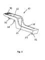
- Fig. 1 schematically shows a fastening device according to the invention with a fastening element 10, which is attached to a connector 12 and connectable to the connector plug 12 basic housing 14.
- the connector 12 has a connector housing 16 consisting of an insulating material with conductor connection elements arranged therein and plug contacts (not shown here) connected to the conductor connection elements.
- the connector 12 is formed as a screw terminal, in which 16 three screw holes 18 are provided on the connector housing, wherein in Fig. 1 , due to the perspective shown here, two of the three screw shafts 18 are covered by the fastener 10. About each of the screw shafts 18 a screw is inserted into the interior of the plug housing 16 in each case.
- the base housing 14 is provided which can be attached by means of solder pins 20 to the circuit board and a plurality of slots not shown here for attaching the connector plug 12 has.
- the fastening element 10 is designed as a film hinge made of a plastic, which has a first fastening region 22 and a second fastening region 24. By means of the first fastening region 22, the fastening element 10 can be fastened to the connecting plug 12.
- the first fastening region 22 of the fastening element 10 has a hook element 26.
- the hook element 26 is preferably flat, wherein the side surfaces 28 of the fastening element 10 are formed as webs, through which the fastening element 10 has sufficient stability. In the unfastened state of the fastener 10, that is, when the fastener 10 is not attached to the plug assembly, the hook member 26 is formed as a wall surface of the fastener 10.
- the hook element 26 formed in the unsecured state as a wall surface can be bent downwards so that an opening 30 is formed on the fastening element 10.
- this opening 30 is in the attached state, as in Fig. 1 shown at least a portion of the screw shaft 18 is inserted, in particular the part of the screw shaft 18, which is arranged elevated from the outer surface of the plug housing 16 so that the screw shaft 18 is clamped between the hook member 26 and the side surfaces 28 formed as webs of the fastener 10.
- the hook element 26 is designed as a spring element, so that the fastening element 10 is mounted at its first attachment portion 22 pivotally mounted on the screw shaft 18.
- the fastener 10 can act as a kind of rocker.
- the fastening element 10 Due to the pivot point of the fastening element 10 on the first fastening region 22, the fastening element 10 is in the position when applying a tensile force on the connector 12 and / or the base housing 14 to remain in its position and not to be solved from this.
- the second fastening region 24 of the fastening element 10 is provided opposite the first fastening region 22 at the other end of the fastening element 10.
- the second fastening region 24 has a latching nose 32 which, in the fastened state of the fastening element 10, abuts against an outer surface of the base housing 14 such that the latching nose 32 engages behind the base housing 14, so that the base housing 14 is clamped between the connector 12 and the latching nose 32 ,
- Fig. 2 is shown in the transfer of the fastener 10 from the unfastened state in the fastened state, the fastener 10 is first hooked to the first mounting portion of the screw shaft 18 of the connector 12. Subsequently, the remainder of the fastener 10 is slid over preferably the entire length of a first side surface 34 of the base housing 14 until the detent 32 abuts the second side surface 36 of the base housing 12 disposed transversely of the first side surface 34 so that the detent 16 engages second side surface 34 of the base housing 14 engages behind.
- the hook element 26 additionally has a bearing element 38 which can be inserted into a corresponding bearing recess provided on the connector housing 16 (not shown here).
- the fastening element 10 also has a grip section 40.
- the handle portion 40 is provided in the region of the first mounting portion 22, the handle portion 40 protrudes beyond the edge region of the plug housing 16 of the connector 12, the fastener 10 can be easily operated by hand and thereby the connector 12 is easily detached from the base housing 14 become. This is particularly advantageous when the plug assembly is arranged, for example, in a cabinet so that there is very little free space between the end face of the plug assembly and the housing wall of the cabinet.
- Characterized in that the fastener 10 can be easily operated by pressing a finger on the handle portion 40, no additional tool for releasing the connector plug 12 is necessary.
- the grip portion 40 preferably has grooved depressions as gripping aid and anti-slip device upon actuation of the grip portion 40.
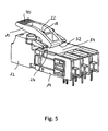
- Fig. 4 and Fig. 5 show two further possible embodiments of such a fastening device, in particular for such a fastener 10, wherein the in Fig. 4 and Fig. 5 fasteners shown have a shorter length than those in Fig. 1 shown embodiment of a fastener.
- the fastener 10 does not span the entire length of the first side surface 34 of the base housing 14.
Applications Claiming Priority (2)
| Application Number | Priority Date | Filing Date | Title |
|---|---|---|---|
| DE102009018715A DE102009018715A1 (de) | 2009-04-27 | 2009-04-27 | Befestigungsvorrichtung zum Befestigen eines Anschlusssteckers an einem Grundgehäuse |
| PCT/EP2010/002572 WO2010124842A1 (de) | 2009-04-27 | 2010-04-27 | Befestigungsvorrichtung zum befestigen eines anschlusssteckers an einem grundgehäuse |
Publications (2)
| Publication Number | Publication Date |
|---|---|
| EP2425497A1 EP2425497A1 (de) | 2012-03-07 |
| EP2425497B1 true EP2425497B1 (de) | 2015-01-07 |
Family
ID=42289777
Family Applications (1)
| Application Number | Title | Priority Date | Filing Date |
|---|---|---|---|
| EP10719734.5A Active EP2425497B1 (de) | 2009-04-27 | 2010-04-27 | Befestigungsvorrichtung zum befestigen eines anschlusssteckers an einem grundgehäuse |
Country Status (5)
| Country | Link |
|---|---|
| US (1) | US8616910B2 (zh) |
| EP (1) | EP2425497B1 (zh) |
| CN (1) | CN102428615B (zh) |
| DE (1) | DE102009018715A1 (zh) |
| WO (1) | WO2010124842A1 (zh) |
Families Citing this family (6)
| Publication number | Priority date | Publication date | Assignee | Title |
|---|---|---|---|---|
| CN104092051A (zh) | 2011-11-23 | 2014-10-08 | 3M创新有限公司 | 电缆连接器和闩锁电缆连接器组件 |
| DE102014107950B4 (de) | 2014-06-05 | 2022-02-03 | Wago Verwaltungsgesellschaft Mbh | Steckverbinderanordnung und Löseelement hierzu |
| DE102017124670B4 (de) * | 2017-10-23 | 2022-03-24 | Wago Verwaltungsgesellschaft Mbh | Elektrische Steckverbindung |
| JP2020184520A (ja) | 2019-04-30 | 2020-11-12 | ヴァーゴ・フェアヴァルトゥングスゲゼルシャフト・エムベーハー | 電気コネクタ機構のコネクタ、およびそれによって形成される電気コネクタ機構 |
| DE102019111164A1 (de) | 2019-04-30 | 2020-11-05 | Wago Verwaltungsgesellschaft Mbh | Steckverbinder einer elektrischen Steckverbindung sowie Set aus Steckverbinder und Funktionselement |
| DE202021105957U1 (de) | 2021-11-01 | 2023-02-03 | WAGO Verwaltungsgesellschaft mit beschränkter Haftung | Zubehörelement und Set aus einem Funktionsbauteil und einem Zubehörelement |
Citations (11)
| Publication number | Priority date | Publication date | Assignee | Title |
|---|---|---|---|---|
| DE8813990U1 (zh) * | 1988-11-09 | 1988-12-22 | F. Wieland Elektrische Industrie Gmbh, 8600 Bamberg, De | |
| EP0813269A2 (de) * | 1996-06-14 | 1997-12-17 | PHOENIX CONTACT GmbH & Co. | Elektrischer Verbinder |
| WO2000055710A1 (de) * | 1999-03-16 | 2000-09-21 | Grzelka Elektronik Gmbh | Stromanschluss |
| US6394824B1 (en) * | 2001-04-04 | 2002-05-28 | Hon Hai Precision Ind. Co., Ltd. | Electrical connector |
| US7128595B2 (en) * | 2005-03-23 | 2006-10-31 | Amphenol Corporation | Electrical connector with positive lock |
| EP1734551A1 (de) * | 2005-06-15 | 2006-12-20 | Moeller GmbH | Steckvorrichtung für eine elektrische Schaltvorrichtung |
| EP1898436A2 (de) * | 2006-09-09 | 2008-03-12 | Moeller GmbH | Steckvorrichtung zum Stecken auf eine elektrische Schaltvorrichtung |
| US7438569B2 (en) * | 2006-09-08 | 2008-10-21 | Tyco Electronics Corporation | Low profile socket connector |
| WO2008125314A1 (de) * | 2007-04-12 | 2008-10-23 | Phoenix Contact Gmbh & Co. Kg | Elektrisches übergabemodul |
| DE202009002159U1 (de) * | 2009-02-14 | 2010-07-15 | Weidmüller Interface GmbH & Co. KG | Steckverbinder, insbesondere für Leiterplatten |
| EP2321875A2 (en) * | 2008-08-15 | 2011-05-18 | 3M Innovative Properties Company | Electrical connector assembly |
Family Cites Families (9)
| Publication number | Priority date | Publication date | Assignee | Title |
|---|---|---|---|---|
| US6350159B1 (en) * | 2000-09-19 | 2002-02-26 | Hon Hai Precision Ind. Co., Ltd. | Arrangement for preventing mismating of connectors having different numbers of terminals |
| TW491424U (en) * | 2000-12-04 | 2002-06-11 | Delta Electronics Inc | Inserting and fixing device |
| DE20201609U1 (de) * | 2002-02-01 | 2003-06-18 | Weidmueller Interface | Steckverbinder |
| KR101080356B1 (ko) * | 2003-10-13 | 2011-11-04 | 삼성전자주식회사 | 박막 트랜지스터, 박막 트랜지스터 표시판 및 표시 장치 |
| US7114980B1 (en) * | 2005-08-11 | 2006-10-03 | Hon Hai Precision Ind. Co., Ltd | Cable connector assembly with latching mechanism |
| DE102005058969B4 (de) * | 2005-12-09 | 2008-01-03 | Phoenix Contact Gmbh & Co. Kg | Verriegelungsvorrichtung für Steckerteil und Grundleiste eines elektrischen Steckverbinders |
| US7226307B1 (en) * | 2006-07-27 | 2007-06-05 | Jess-Link Products Co., Ltd. | Plug connector |
| US20080050961A1 (en) * | 2006-08-24 | 2008-02-28 | Hon Hai Precision Ind. Co., Ltd. | Electrical connector with improved latching structure |
| US7534125B1 (en) * | 2008-02-26 | 2009-05-19 | Tyco Electronics Corporation | Electrical connector having a multi-directional latching mechanism |
-
2009
- 2009-04-27 DE DE102009018715A patent/DE102009018715A1/de not_active Withdrawn
-
2010
- 2010-04-27 US US13/266,456 patent/US8616910B2/en not_active Expired - Fee Related
- 2010-04-27 EP EP10719734.5A patent/EP2425497B1/de active Active
- 2010-04-27 WO PCT/EP2010/002572 patent/WO2010124842A1/de active Application Filing
- 2010-04-27 CN CN201080018850.4A patent/CN102428615B/zh active Active
Patent Citations (11)
| Publication number | Priority date | Publication date | Assignee | Title |
|---|---|---|---|---|
| DE8813990U1 (zh) * | 1988-11-09 | 1988-12-22 | F. Wieland Elektrische Industrie Gmbh, 8600 Bamberg, De | |
| EP0813269A2 (de) * | 1996-06-14 | 1997-12-17 | PHOENIX CONTACT GmbH & Co. | Elektrischer Verbinder |
| WO2000055710A1 (de) * | 1999-03-16 | 2000-09-21 | Grzelka Elektronik Gmbh | Stromanschluss |
| US6394824B1 (en) * | 2001-04-04 | 2002-05-28 | Hon Hai Precision Ind. Co., Ltd. | Electrical connector |
| US7128595B2 (en) * | 2005-03-23 | 2006-10-31 | Amphenol Corporation | Electrical connector with positive lock |
| EP1734551A1 (de) * | 2005-06-15 | 2006-12-20 | Moeller GmbH | Steckvorrichtung für eine elektrische Schaltvorrichtung |
| US7438569B2 (en) * | 2006-09-08 | 2008-10-21 | Tyco Electronics Corporation | Low profile socket connector |
| EP1898436A2 (de) * | 2006-09-09 | 2008-03-12 | Moeller GmbH | Steckvorrichtung zum Stecken auf eine elektrische Schaltvorrichtung |
| WO2008125314A1 (de) * | 2007-04-12 | 2008-10-23 | Phoenix Contact Gmbh & Co. Kg | Elektrisches übergabemodul |
| EP2321875A2 (en) * | 2008-08-15 | 2011-05-18 | 3M Innovative Properties Company | Electrical connector assembly |
| DE202009002159U1 (de) * | 2009-02-14 | 2010-07-15 | Weidmüller Interface GmbH & Co. KG | Steckverbinder, insbesondere für Leiterplatten |
Also Published As
| Publication number | Publication date |
|---|---|
| DE102009018715A1 (de) | 2010-11-04 |
| US8616910B2 (en) | 2013-12-31 |
| EP2425497A1 (de) | 2012-03-07 |
| US20120045922A1 (en) | 2012-02-23 |
| CN102428615A (zh) | 2012-04-25 |
| CN102428615B (zh) | 2014-06-18 |
| WO2010124842A1 (de) | 2010-11-04 |
Similar Documents
| Publication | Publication Date | Title |
|---|---|---|
| EP3248248B1 (de) | Elektrische anschlussklemme mit zweiteiligem betätigungselement | |
| DE102008006258B4 (de) | Vorrichtung zum Abziehen einer Anschlussklemme | |
| DE102019135203A1 (de) | Anschlussanordnung, Anschlusseinrichtung sowie elektronisches Gerät | |
| EP2425497B1 (de) | Befestigungsvorrichtung zum befestigen eines anschlusssteckers an einem grundgehäuse | |
| DE102010017262B4 (de) | Anschlussstecker mit Verriegelungseinrichtung | |
| EP2625747B2 (de) | Zusatzanschlussstecker | |
| EP3084891B1 (de) | Metallisches schutzleiteranschlusselement und elektrische reihenklemme | |
| DE202016105358U1 (de) | Steckkontakt mit Schneid-Klemm-Gabel | |
| EP3375048A1 (de) | Steckkontakt | |
| EP1912285A1 (de) | Elektrisches oder elektronisches Gerät | |
| EP3021421B1 (de) | Anschlussvorrichtung für mehrleiterkabel | |
| EP1245139A1 (de) | Bestätigungselement zum ein- und aushebeln von flachbaugruppen mit verriegelungsschieber, frontelement für eine flachbaugruppe mit betätigungselement und baugruppenträger zur aufnahme von flachbaugruppen | |
| EP2356892B1 (de) | Befestigungselement für eine erweiterungskarte sowie entsprechende anordnung eines befestigungselements mit einer erweiterungskarte in einem computersystem | |
| DE102014117699B4 (de) | Leiterklemmeneinrichtung | |
| DE202010003385U1 (de) | Elektrische Anschlussklemme | |
| EP3300175B1 (de) | Steckkontakt mit schneid-klemm-gabel | |
| DE102017128604A1 (de) | Elektrische Steckverbindung zur Datenübertragung | |
| AT505733A2 (de) | Elektronisches gerät und leiterplatte mit steckerleiste | |
| DE102019113069B3 (de) | Halterahmen und Steckverbinder mit einem derartigen Halterahmen | |
| EP2514036A1 (de) | Verbindungssystem zum verbinden eines einreihigen gehäuses mit einem anschlusselement | |
| DE102022125266A1 (de) | Anschlussklemme | |
| EP4292171A1 (de) | Elektrischer steckverbinder | |
| DE102022113144A1 (de) | Steckverbinder mit einer rasteinrichtung zur verriegelung einer steckverbindung mit einem gegensteckverbinder, gegensteckverbinder sowie anordnung mit einem steckverbinder und einem gegensteckverbinder | |
| LU93147B1 (de) | Anschlussklemme | |
| DE202009017067U1 (de) | Verbindungssystem zum Verbinden eines einreihigen Gehäuses mit einem Anschlusselement |
Legal Events
| Date | Code | Title | Description |
|---|---|---|---|
| PUAI | Public reference made under article 153(3) epc to a published international application that has entered the european phase |
Free format text: ORIGINAL CODE: 0009012 |
|
| 17P | Request for examination filed |
Effective date: 20111123 |
|
| AK | Designated contracting states |
Kind code of ref document: A1 Designated state(s): AT BE BG CH CY CZ DE DK EE ES FI FR GB GR HR HU IE IS IT LI LT LU LV MC MK MT NL NO PL PT RO SE SI SK SM TR |
|
| DAX | Request for extension of the european patent (deleted) | ||
| 17Q | First examination report despatched |
Effective date: 20130308 |
|
| REG | Reference to a national code |
Ref country code: DE Ref legal event code: R079 Ref document number: 502010008678 Country of ref document: DE Free format text: PREVIOUS MAIN CLASS: H01R0013639000 Ipc: H01R0013627000 |
|
| GRAP | Despatch of communication of intention to grant a patent |
Free format text: ORIGINAL CODE: EPIDOSNIGR1 |
|
| RIC1 | Information provided on ipc code assigned before grant |
Ipc: H01R 13/627 20060101AFI20140711BHEP Ipc: H01R 13/639 20060101ALI20140711BHEP |
|
| INTG | Intention to grant announced |
Effective date: 20140731 |
|
| GRAS | Grant fee paid |
Free format text: ORIGINAL CODE: EPIDOSNIGR3 |
|
| GRAA | (expected) grant |
Free format text: ORIGINAL CODE: 0009210 |
|
| AK | Designated contracting states |
Kind code of ref document: B1 Designated state(s): AT BE BG CH CY CZ DE DK EE ES FI FR GB GR HR HU IE IS IT LI LT LU LV MC MK MT NL NO PL PT RO SE SI SK SM TR |
|
| REG | Reference to a national code |
Ref country code: GB Ref legal event code: FG4D Free format text: NOT ENGLISH |
|
| REG | Reference to a national code |
Ref country code: CH Ref legal event code: EP |
|
| REG | Reference to a national code |
Ref country code: IE Ref legal event code: FG4D Free format text: LANGUAGE OF EP DOCUMENT: GERMAN |
|
| REG | Reference to a national code |
Ref country code: AT Ref legal event code: REF Ref document number: 706305 Country of ref document: AT Kind code of ref document: T Effective date: 20150215 |
|
| REG | Reference to a national code |
Ref country code: DE Ref legal event code: R096 Ref document number: 502010008678 Country of ref document: DE Effective date: 20150219 |
|
| REG | Reference to a national code |
Ref country code: FR Ref legal event code: PLFP Year of fee payment: 6 |
|
| REG | Reference to a national code |
Ref country code: NL Ref legal event code: VDEP Effective date: 20150107 |
|
| REG | Reference to a national code |
Ref country code: LT Ref legal event code: MG4D |
|
| PG25 | Lapsed in a contracting state [announced via postgrant information from national office to epo] |
Ref country code: HR Free format text: LAPSE BECAUSE OF FAILURE TO SUBMIT A TRANSLATION OF THE DESCRIPTION OR TO PAY THE FEE WITHIN THE PRESCRIBED TIME-LIMIT Effective date: 20150107 Ref country code: SE Free format text: LAPSE BECAUSE OF FAILURE TO SUBMIT A TRANSLATION OF THE DESCRIPTION OR TO PAY THE FEE WITHIN THE PRESCRIBED TIME-LIMIT Effective date: 20150107 Ref country code: ES Free format text: LAPSE BECAUSE OF FAILURE TO SUBMIT A TRANSLATION OF THE DESCRIPTION OR TO PAY THE FEE WITHIN THE PRESCRIBED TIME-LIMIT Effective date: 20150107 Ref country code: FI Free format text: LAPSE BECAUSE OF FAILURE TO SUBMIT A TRANSLATION OF THE DESCRIPTION OR TO PAY THE FEE WITHIN THE PRESCRIBED TIME-LIMIT Effective date: 20150107 Ref country code: NO Free format text: LAPSE BECAUSE OF FAILURE TO SUBMIT A TRANSLATION OF THE DESCRIPTION OR TO PAY THE FEE WITHIN THE PRESCRIBED TIME-LIMIT Effective date: 20150407 Ref country code: BG Free format text: LAPSE BECAUSE OF FAILURE TO SUBMIT A TRANSLATION OF THE DESCRIPTION OR TO PAY THE FEE WITHIN THE PRESCRIBED TIME-LIMIT Effective date: 20150407 Ref country code: LT Free format text: LAPSE BECAUSE OF FAILURE TO SUBMIT A TRANSLATION OF THE DESCRIPTION OR TO PAY THE FEE WITHIN THE PRESCRIBED TIME-LIMIT Effective date: 20150107 |
|
| PG25 | Lapsed in a contracting state [announced via postgrant information from national office to epo] |
Ref country code: PL Free format text: LAPSE BECAUSE OF FAILURE TO SUBMIT A TRANSLATION OF THE DESCRIPTION OR TO PAY THE FEE WITHIN THE PRESCRIBED TIME-LIMIT Effective date: 20150107 Ref country code: IS Free format text: LAPSE BECAUSE OF FAILURE TO SUBMIT A TRANSLATION OF THE DESCRIPTION OR TO PAY THE FEE WITHIN THE PRESCRIBED TIME-LIMIT Effective date: 20150507 Ref country code: LV Free format text: LAPSE BECAUSE OF FAILURE TO SUBMIT A TRANSLATION OF THE DESCRIPTION OR TO PAY THE FEE WITHIN THE PRESCRIBED TIME-LIMIT Effective date: 20150107 Ref country code: GR Free format text: LAPSE BECAUSE OF FAILURE TO SUBMIT A TRANSLATION OF THE DESCRIPTION OR TO PAY THE FEE WITHIN THE PRESCRIBED TIME-LIMIT Effective date: 20150408 Ref country code: NL Free format text: LAPSE BECAUSE OF FAILURE TO SUBMIT A TRANSLATION OF THE DESCRIPTION OR TO PAY THE FEE WITHIN THE PRESCRIBED TIME-LIMIT Effective date: 20150107 |
|
| REG | Reference to a national code |
Ref country code: DE Ref legal event code: R097 Ref document number: 502010008678 Country of ref document: DE |
|
| PG25 | Lapsed in a contracting state [announced via postgrant information from national office to epo] |
Ref country code: SK Free format text: LAPSE BECAUSE OF FAILURE TO SUBMIT A TRANSLATION OF THE DESCRIPTION OR TO PAY THE FEE WITHIN THE PRESCRIBED TIME-LIMIT Effective date: 20150107 Ref country code: DK Free format text: LAPSE BECAUSE OF FAILURE TO SUBMIT A TRANSLATION OF THE DESCRIPTION OR TO PAY THE FEE WITHIN THE PRESCRIBED TIME-LIMIT Effective date: 20150107 Ref country code: RO Free format text: LAPSE BECAUSE OF FAILURE TO SUBMIT A TRANSLATION OF THE DESCRIPTION OR TO PAY THE FEE WITHIN THE PRESCRIBED TIME-LIMIT Effective date: 20150107 Ref country code: CZ Free format text: LAPSE BECAUSE OF FAILURE TO SUBMIT A TRANSLATION OF THE DESCRIPTION OR TO PAY THE FEE WITHIN THE PRESCRIBED TIME-LIMIT Effective date: 20150107 Ref country code: EE Free format text: LAPSE BECAUSE OF FAILURE TO SUBMIT A TRANSLATION OF THE DESCRIPTION OR TO PAY THE FEE WITHIN THE PRESCRIBED TIME-LIMIT Effective date: 20150107 |
|
| PLBE | No opposition filed within time limit |
Free format text: ORIGINAL CODE: 0009261 |
|
| STAA | Information on the status of an ep patent application or granted ep patent |
Free format text: STATUS: NO OPPOSITION FILED WITHIN TIME LIMIT |
|
| PG25 | Lapsed in a contracting state [announced via postgrant information from national office to epo] |
Ref country code: LU Free format text: LAPSE BECAUSE OF FAILURE TO SUBMIT A TRANSLATION OF THE DESCRIPTION OR TO PAY THE FEE WITHIN THE PRESCRIBED TIME-LIMIT Effective date: 20150427 Ref country code: MC Free format text: LAPSE BECAUSE OF FAILURE TO SUBMIT A TRANSLATION OF THE DESCRIPTION OR TO PAY THE FEE WITHIN THE PRESCRIBED TIME-LIMIT Effective date: 20150107 |
|
| REG | Reference to a national code |
Ref country code: CH Ref legal event code: PL |
|
| 26N | No opposition filed |
Effective date: 20151008 |
|
| REG | Reference to a national code |
Ref country code: IE Ref legal event code: MM4A |
|
| PG25 | Lapsed in a contracting state [announced via postgrant information from national office to epo] |
Ref country code: CH Free format text: LAPSE BECAUSE OF NON-PAYMENT OF DUE FEES Effective date: 20150430 Ref country code: LI Free format text: LAPSE BECAUSE OF NON-PAYMENT OF DUE FEES Effective date: 20150430 |
|
| PG25 | Lapsed in a contracting state [announced via postgrant information from national office to epo] |
Ref country code: SI Free format text: LAPSE BECAUSE OF FAILURE TO SUBMIT A TRANSLATION OF THE DESCRIPTION OR TO PAY THE FEE WITHIN THE PRESCRIBED TIME-LIMIT Effective date: 20150107 |
|
| REG | Reference to a national code |
Ref country code: FR Ref legal event code: PLFP Year of fee payment: 7 |
|
| PG25 | Lapsed in a contracting state [announced via postgrant information from national office to epo] |
Ref country code: IE Free format text: LAPSE BECAUSE OF NON-PAYMENT OF DUE FEES Effective date: 20150427 |
|
| REG | Reference to a national code |
Ref country code: AT Ref legal event code: MM01 Ref document number: 706305 Country of ref document: AT Kind code of ref document: T Effective date: 20150427 |
|
| PG25 | Lapsed in a contracting state [announced via postgrant information from national office to epo] |
Ref country code: AT Free format text: LAPSE BECAUSE OF NON-PAYMENT OF DUE FEES Effective date: 20150427 |
|
| PGFP | Annual fee paid to national office [announced via postgrant information from national office to epo] |
Ref country code: FR Payment date: 20160423 Year of fee payment: 7 |
|
| PG25 | Lapsed in a contracting state [announced via postgrant information from national office to epo] |
Ref country code: MT Free format text: LAPSE BECAUSE OF FAILURE TO SUBMIT A TRANSLATION OF THE DESCRIPTION OR TO PAY THE FEE WITHIN THE PRESCRIBED TIME-LIMIT Effective date: 20150107 |
|
| PG25 | Lapsed in a contracting state [announced via postgrant information from national office to epo] |
Ref country code: HU Free format text: LAPSE BECAUSE OF FAILURE TO SUBMIT A TRANSLATION OF THE DESCRIPTION OR TO PAY THE FEE WITHIN THE PRESCRIBED TIME-LIMIT; INVALID AB INITIO Effective date: 20100427 Ref country code: SM Free format text: LAPSE BECAUSE OF FAILURE TO SUBMIT A TRANSLATION OF THE DESCRIPTION OR TO PAY THE FEE WITHIN THE PRESCRIBED TIME-LIMIT Effective date: 20150107 |
|
| PG25 | Lapsed in a contracting state [announced via postgrant information from national office to epo] |
Ref country code: CY Free format text: LAPSE BECAUSE OF FAILURE TO SUBMIT A TRANSLATION OF THE DESCRIPTION OR TO PAY THE FEE WITHIN THE PRESCRIBED TIME-LIMIT Effective date: 20150107 |
|
| PG25 | Lapsed in a contracting state [announced via postgrant information from national office to epo] |
Ref country code: BE Free format text: LAPSE BECAUSE OF NON-PAYMENT OF DUE FEES Effective date: 20150430 Ref country code: PT Free format text: LAPSE BECAUSE OF FAILURE TO SUBMIT A TRANSLATION OF THE DESCRIPTION OR TO PAY THE FEE WITHIN THE PRESCRIBED TIME-LIMIT Effective date: 20150507 |
|
| PGFP | Annual fee paid to national office [announced via postgrant information from national office to epo] |
Ref country code: GB Payment date: 20170427 Year of fee payment: 8 |
|
| PG25 | Lapsed in a contracting state [announced via postgrant information from national office to epo] |
Ref country code: TR Free format text: LAPSE BECAUSE OF FAILURE TO SUBMIT A TRANSLATION OF THE DESCRIPTION OR TO PAY THE FEE WITHIN THE PRESCRIBED TIME-LIMIT Effective date: 20150107 |
|
| REG | Reference to a national code |
Ref country code: FR Ref legal event code: ST Effective date: 20171229 |
|
| PG25 | Lapsed in a contracting state [announced via postgrant information from national office to epo] |
Ref country code: FR Free format text: LAPSE BECAUSE OF NON-PAYMENT OF DUE FEES Effective date: 20170502 |
|
| PG25 | Lapsed in a contracting state [announced via postgrant information from national office to epo] |
Ref country code: MK Free format text: LAPSE BECAUSE OF FAILURE TO SUBMIT A TRANSLATION OF THE DESCRIPTION OR TO PAY THE FEE WITHIN THE PRESCRIBED TIME-LIMIT Effective date: 20150107 |
|
| GBPC | Gb: european patent ceased through non-payment of renewal fee |
Effective date: 20180427 |
|
| PG25 | Lapsed in a contracting state [announced via postgrant information from national office to epo] |
Ref country code: GB Free format text: LAPSE BECAUSE OF NON-PAYMENT OF DUE FEES Effective date: 20180427 |
|
| PGFP | Annual fee paid to national office [announced via postgrant information from national office to epo] |
Ref country code: IT Payment date: 20190419 Year of fee payment: 10 |
|
| PG25 | Lapsed in a contracting state [announced via postgrant information from national office to epo] |
Ref country code: IT Free format text: LAPSE BECAUSE OF NON-PAYMENT OF DUE FEES Effective date: 20200427 |
|
| P01 | Opt-out of the competence of the unified patent court (upc) registered |
Effective date: 20230424 |
|
| PGFP | Annual fee paid to national office [announced via postgrant information from national office to epo] |
Ref country code: DE Payment date: 20230627 Year of fee payment: 14 |