EP2421780B1 - ANORDNUNG ZUR BEVORRATUNG GROßER LÄNGEN EINES FLEXIBLEN GEGENSTANDES - Google Patents
ANORDNUNG ZUR BEVORRATUNG GROßER LÄNGEN EINES FLEXIBLEN GEGENSTANDES Download PDFInfo
- Publication number
- EP2421780B1 EP2421780B1 EP10724687.8A EP10724687A EP2421780B1 EP 2421780 B1 EP2421780 B1 EP 2421780B1 EP 10724687 A EP10724687 A EP 10724687A EP 2421780 B1 EP2421780 B1 EP 2421780B1
- Authority
- EP
- European Patent Office
- Prior art keywords
- drum
- winding
- winding drum
- drive
- drums
- Prior art date
- Legal status (The legal status is an assumption and is not a legal conclusion. Google has not performed a legal analysis and makes no representation as to the accuracy of the status listed.)
- Not-in-force
Links
- 238000004804 winding Methods 0.000 claims description 114
- 230000033001 locomotion Effects 0.000 claims description 9
- 230000001360 synchronised effect Effects 0.000 claims description 7
- XLYOFNOQVPJJNP-UHFFFAOYSA-N water Substances O XLYOFNOQVPJJNP-UHFFFAOYSA-N 0.000 description 10
- 238000000034 method Methods 0.000 description 5
- 230000008569 process Effects 0.000 description 5
- 239000000463 material Substances 0.000 description 3
- 238000011161 development Methods 0.000 description 2
- 230000018109 developmental process Effects 0.000 description 2
- 230000007246 mechanism Effects 0.000 description 2
- 230000008901 benefit Effects 0.000 description 1
- 230000005540 biological transmission Effects 0.000 description 1
- 238000013461 design Methods 0.000 description 1
- 239000012530 fluid Substances 0.000 description 1
- 230000005484 gravity Effects 0.000 description 1
- 229910001385 heavy metal Inorganic materials 0.000 description 1
- 238000012544 monitoring process Methods 0.000 description 1
- 239000007787 solid Substances 0.000 description 1
- 239000000126 substance Substances 0.000 description 1
- 238000012549 training Methods 0.000 description 1
- 230000007704 transition Effects 0.000 description 1
Images



Classifications
-
- B—PERFORMING OPERATIONS; TRANSPORTING
- B65—CONVEYING; PACKING; STORING; HANDLING THIN OR FILAMENTARY MATERIAL
- B65H—HANDLING THIN OR FILAMENTARY MATERIAL, e.g. SHEETS, WEBS, CABLES
- B65H49/00—Unwinding or paying-out filamentary material; Supporting, storing or transporting packages from which filamentary material is to be withdrawn or paid-out
- B65H49/18—Methods or apparatus in which packages rotate
- B65H49/20—Package-supporting devices
- B65H49/24—Rollers
-
- B—PERFORMING OPERATIONS; TRANSPORTING
- B65—CONVEYING; PACKING; STORING; HANDLING THIN OR FILAMENTARY MATERIAL
- B65H—HANDLING THIN OR FILAMENTARY MATERIAL, e.g. SHEETS, WEBS, CABLES
- B65H49/00—Unwinding or paying-out filamentary material; Supporting, storing or transporting packages from which filamentary material is to be withdrawn or paid-out
- B65H49/18—Methods or apparatus in which packages rotate
- B65H49/20—Package-supporting devices
- B65H49/32—Stands or frameworks
-
- B—PERFORMING OPERATIONS; TRANSPORTING
- B65—CONVEYING; PACKING; STORING; HANDLING THIN OR FILAMENTARY MATERIAL
- B65H—HANDLING THIN OR FILAMENTARY MATERIAL, e.g. SHEETS, WEBS, CABLES
- B65H54/00—Winding, coiling, or depositing filamentary material
- B65H54/02—Winding and traversing material on to reels, bobbins, tubes, or like package cores or formers
- B65H54/10—Winding and traversing material on to reels, bobbins, tubes, or like package cores or formers for making packages of specified shapes or on specified types of bobbins, tubes, cores, or formers
- B65H54/20—Winding and traversing material on to reels, bobbins, tubes, or like package cores or formers for making packages of specified shapes or on specified types of bobbins, tubes, cores, or formers forming multiple packages
-
- B—PERFORMING OPERATIONS; TRANSPORTING
- B65—CONVEYING; PACKING; STORING; HANDLING THIN OR FILAMENTARY MATERIAL
- B65H—HANDLING THIN OR FILAMENTARY MATERIAL, e.g. SHEETS, WEBS, CABLES
- B65H75/00—Storing webs, tapes, or filamentary material, e.g. on reels
- B65H75/02—Cores, formers, supports, or holders for coiled, wound, or folded material, e.g. reels, spindles, bobbins, cop tubes, cans, mandrels or chucks
- B65H75/04—Kinds or types
- B65H75/08—Kinds or types of circular or polygonal cross-section
- B65H75/14—Kinds or types of circular or polygonal cross-section with two end flanges
- B65H75/146—Kinds or types of circular or polygonal cross-section with two end flanges with at least one intermediate flange between the two end flanges
-
- B—PERFORMING OPERATIONS; TRANSPORTING
- B65—CONVEYING; PACKING; STORING; HANDLING THIN OR FILAMENTARY MATERIAL
- B65H—HANDLING THIN OR FILAMENTARY MATERIAL, e.g. SHEETS, WEBS, CABLES
- B65H2601/00—Problem to be solved or advantage achieved
- B65H2601/10—Ensuring correct operation
- B65H2601/12—Compensating; Taking-up
- B65H2601/124—Imbalance
-
- B—PERFORMING OPERATIONS; TRANSPORTING
- B65—CONVEYING; PACKING; STORING; HANDLING THIN OR FILAMENTARY MATERIAL
- B65H—HANDLING THIN OR FILAMENTARY MATERIAL, e.g. SHEETS, WEBS, CABLES
- B65H2701/00—Handled material; Storage means
- B65H2701/30—Handled filamentary material
- B65H2701/34—Handled filamentary material electric cords or electric power cables
-
- B—PERFORMING OPERATIONS; TRANSPORTING
- B65—CONVEYING; PACKING; STORING; HANDLING THIN OR FILAMENTARY MATERIAL
- B65H—HANDLING THIN OR FILAMENTARY MATERIAL, e.g. SHEETS, WEBS, CABLES
- B65H2701/00—Handled material; Storage means
- B65H2701/50—Storage means for webs, tapes, or filamentary material
- B65H2701/52—Integration of elements inside the core or reel
- B65H2701/524—Weights
Definitions
- the invention relates to an arrangement for storing long lengths of an elongated, flexible object, in particular electric cable, hose or tubes.
- the arrangement may be stationary or mounted on a vehicle.
- a vehicle in particular a non-powered watercraft, such as a floating pontoon in question.
- floating cable laying known, of which submarine cables are laid on the seabed.
- the cable is inserted into a cable space of the watercraft in order to lay it from there overboard to the seabed (eg. JP 2000139013 A ).
- the alternative is to stock one or more cable sections on cable reels; for example, be the GB 1451407 quoted here. It follows that only a limited length of cable can be wound on a cable reel. If one wishes to lay a greater length of cable than is available on a single cable reel, the cable section must be spliced from a first cable reel to its full unwinding from the first cable reel to the beginning of the cable section of a second cable reel. Larger lengths of cable can not be wound continuously on two independent cable reels and unwound because the reel drum core is wrapped at least once and the wrap can not be loosened without disconnecting (interrupting) the cable section.
- the US 2 958 478 shows an arrangement with a single winding drum on a footing for storing an elongated object.
- the winding drum consists of two drum disks of uniform diameter, between which a cylindrical drum core is present.
- the winding drum is elevated so that the drum core of the winding drum is parallel to the standing surface, wherein wheel rims of the drum discs of the winding drum are mounted on free-running rollers.
- each winding drum can be charged with its own winding material.
- a device for feeding the winding drums is not described.
- the drive is further designed so that different rotational speeds of the winding drums are allowed, which can occur due to different forces and frictional resistance on the wound winding material.
- a plurality of winding drums are to be loadable with a continuous length of an elongate, flexible article without having to splice separate sections of the article.
- the arrangement is characterized in that it has a plurality of drive devices in the form of drivable rollers.
- the drivable rollers may be used to engage a single winding drum, or driven rollers may be engaged on a plurality of winding drums.
- the arrangement comprises: an apparatus for winding reeling drums in a position in which the axes of the reeling drums are parallel to the horizontal support surface and the axles are arranged in a straight line one behind the other, a drive device for at least one reeling drum about its axis and a device for feeding (winding and unwinding the object) at least one winding drum with the object.
- the arrangement may be stationary or mounted on a vehicle, in particular an unpowered watercraft, for example a floating pontoon.
- the particular advantage of the invention is that a flexible, elongated object can be applied whose length is greater than the capacity of a single winding drum. Should a flexible, elongated object be stored on several winding drums, this is hardly possible without splicing of individual sections of the object. A given footprint (total length of a vehicle) can be exploited in almost the entire length.
- a winding drum has the special features that on at least one drum disc Einfädelrome for the subject (electrical cable, pipeline, flexible tube) is present and at each Einfädelrome an insert is present with which an opening formed by the Einfädelmal in the rim of the drum disc can be bridged ,
- the elongate, flexible article may be a hose, an electrical cable, a semi-finished cable or the like.
- the drive device can be designed such that at least one of the rollers designed as a drive can be set in synchronous rotary motion. Furthermore, a plurality of drive devices may be present and arranged such that all winding drums can be set in synchronous rotation. Between the winding drums connecting elements (for example, struts) are present, with which a rigid connection between the winding drums can be produced.
- the drive device can be arranged sunk in the floor space, so that it can be covered when not in use by heavy metal or concrete slabs, so that the covered area of vehicles is passable.
- each winding drum may be formed such that wheel rims of the drum discs are mounted on rollers, of which at least one - as mentioned - is rotatably driven.
- the wheels and wheel rims can be equipped with a flat surface or with a profiled surface.
- rollers and wheel rims can grasp friction (force) together.
- profiled surfaces may be formed on rollers and wheel rims, so that rollers and wheel rims engage with one another in a form-fitting manner.
- the training can be designed as a toothing (gear and ring gear on the circumference of a drum disc).
- a threading window for the object (electric cable) should be present.
- a flow screw may be present, which continues at the threading window starting spiraling to the drum core.
- the drain screw is located on the inside surface of a drum disk or inner surface of a support disk first reached by the object during a loading operation.
- a winding drum in particular for the arrangement according to the invention, consisting of two drum discs, between which a cylindrical drum core is present, should have the following features that at least one rim of a drum disc a wheel rim interrupting Einfädelmal and an insert is present, with which by the Threading window interrupted wheel rim is bridgeable.
- An alternative winding drum in particular for the arrangement according to the invention, can be designed as follows. It has two drum disks of uniform diameter with a cylindrical drum core between the drum discs, wherein the length of the drum core is interrupted in a uniform subdivision, and there is in each case formed as a support disk drum disc. The support discs run on support wheels on their rim. Thus, the weights are intercepted, which are generated by the increased length of the drum core and by the weight of the applied object (electric cable).
- the subdivision of the drum core can in the pattern 1/2: 1/2 (here a support disk on the drum core); 1/3: 1/3: 1/3 (here two support disks); 1/4: 1/4: 1/4: 1/4 (here three support disks on the drum core) and so on - be made depending on the length of the drum core.
- the support disks may have the same diameter as the end drum disks. The diameter may also be different from the diameter of the end drum discs. It depends on the location of the support rollers.
- This alternative winding drum also has on at least one wheel rim of a support disk, a wheel rim interrupting Einfädelrome and there is an insert with which the opening formed on the rim through the threading window can be bridged.
- the winding drums can therefore be formed in the interior of the drum core with at least one container for receiving additional weights solid or fluid substances.
- a plurality of distributed over the diameter of containers are installed, which are preferably designed as water tanks. These can be filled and emptied relatively quickly. After balancing the drive mechanism can be immediately restarted.
- An electronic monitoring of the drives should be designed so that the torques occurring or the electrical power consumption on the drive rollers can be detected by means of an electronic sensor arrangement and in the occurrence of critical quantities of torque or power consumption, which can imply unbalance, an alarm message and / or a Information on the location and size of the imbalance is delivered.
- the Fig. 1 shows a pontoon in a shortened side view with several winding drums (T1 to T5) on the deck (floor space De) of the pontoon 100th Die
- Fig. 2 shows a corresponding, shortened plan view.
- the axes A of the winding drums are positioned with respect to the center of gravity of the structure in the longitudinal center of the deck.
- the number of winding drums is determined by the length of the pontoon, so that the length and area of the deck are utilized as optimally as possible.
- the winding drums T1 ... T5 each have two drum disks (F1 ', F1 ") of a uniform diameter, and between the drum disks there is a cylindrical drum core TK on which the object (preferably a submarine cable) can be wound.
- T5 are elevated in such a position that the axes A of the winding drums are parallel to the standing surface De and the axes A are arranged in a straight line one behind the other
- a driving device for at least one winding drum T1 ... T3 for rotating a winding drum its axis
- the drive (reference A1, A2) is in Fig. 3 indicated in the drawing.
- Modules M1 to M3 which are set up for the power supply, for the hydraulics, for the control, for tools and other functions.
- the pontoon also has in particular windlasses 32.
- the winding drums are fed one by one by an electric cable, which is transported via a cable entry KE (left - at the bow - in the figure) onto the pontoon.
- the electric cable is taken over by the loading device and transferred to a trolley LK.
- a mounting arm 40 is provided, from which the cable is guided to a winding drum.
- the front end of the cable on the rails Sch on running trolley LK and the mounting arm 40 to the first winding drum T1 introduced.
- the sequence of movements Be of the trolley LK with the mounting arm 40 is indicated.
- the electric cable is applied beginning with a first layer on the drum core TK of the starting winding drum T1 and then further wound layer upon layer until the capacity of the first winding drum is reached.
- the electric cable is then continued from the first winding drum to the second winding drum T2.
- the electric cable is passed through a threading window EF1 'in the right drum pulley EF1 "(the first winding drum T1) through a corresponding threading window EF2' in the left drum pulley EF2 'of the second winding drum T1
- FIGS. 3 and 4 shown in detail.
- the threading windows are closed by inserts, the wheel rims of the drum discs are opened only at the moment of threading the cable - at standstill of the winding drums.
- the winding process is kept in motion by one or more drive devices A1, A2. Due to the transition of the electric cable from the first winding drum to the second winding drum T2 and further from each subsequent winding drum to the last winding drum (T5), it is imperative that the winding drums are placed in synchronous rotation. This can be realized by each winding drum is rotated by its own drive and an electronic control is used to make the rotations of all participating winding drums rotationally synchronized. The synchronous rotational movement of the winding drums can also be achieved in that only one winding drum is acted upon by a drive, and the winding drums are rigidly connected to each other with connecting elements 20, so that they perform uniformly the same rotation.
- the rotational movement by the drive device is set in the unwinding process in the opposite direction, whereby the unwinding (and unthreading through the threading window) takes place in reverse sequence as when winding up.
- Each winding drum T1 ... T5 is supported in such a way that the wheel rims RK1 '... RK3 "of the drum disks F1' ... F3" are mounted on rollers (A1) (see also FIG 3 and 4 ). About at least one of these roles, at least one winding drum should be driven to rotate.
- the rollers A1, A2 are used for storage, guidance and the drive of the wheel rims. There may well be more than two roles A1, A2 - for example, up to twelve. The rollers and the wheel rims can engage either positively or positively.
- the design of a positive engagement may be arranged on a profiled surface of the roller and the rim, or even as a toothing on gear (on the roller) and ring gear (on the rim) of at least one wheel rim.
- a frictional transmission of the rotational movement can be achieved by friction between rollers and wheel rims, wherein Rollers and wheel rims have relatively smooth or slightly profiled surfaces.
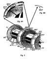
- the Figures 3, 4A and 4B show details of the winding drums T1 to T3.
- the first winding drum (starting drum T1) is located on the left in the drawing of Fig. 3
- a last winding drum T3 is located on the right in the drawing. From the latter, only the left drum disc is visible.
- a threading window EF3 is not visible on the left wheel rim of the third winding drum T3.”
- the threading windows are offset by an angle to the respective adjacent winding drum If the engagement of drive A1, A2 with the respective rim is not continuously possible, it is therefore envisaged that the respective threading windows are closed again by means of an insert EE3 '... EE2 "after threading through the electric cable. This gives the wheel rims a gapless edge.
- An insert EE1 '... EE2 is loosened or fastened by means of screws or clamps on the wheel rim RK1' ... RK3" of the pulley F1 '... F3 "
- Fig. 4B shows the insert EE2 "as a single illustration
- the outer surface of the insert EE2" is also formed (smooth, profiled, or serrated) as the entire surface of the rim.
- a flow screw (S1, S2) is provided on one of the inner sides of the pulley discs (F1 '... F3 ") of each winding drum
- the flow screw serves to guide the electric cable from the place of threading on the threading window to the diameter, or the outer surface of the drum core
- the auger has a spiral shape approximately equal in width to the diameter of an electric cable
- the auger starts at the threading window and continues in a spiraling radius tapering towards the drum core
- Direction of the charging process (winding) of the electric cable is first passed; Figures 1 and 2 ie in each case on the left drum disc of the second, third winding drum (and so on).
- At the start drum (T1) no flow screw must be present, since the electric cable is guided on the starting drum of the mounting arm 40 of the trolley LK directly on the drum core.
- the Fig. 5 shows a winding drum with distant in the rear third lateral surface of the drum core TK1.
- seven (in part) containers designed as cylinders are visible for receiving additional weights.
- the containers WT are parallel to the axis A (symmetry or cylinder axis) of the winding drum and are filled with water fillable.
- On the front of the winding drum holder can be seen between the spokes, in which valves are used to fill with water.
- the winding drum is rotationally driven by the external rotary drive A1, A2, as already in Fig. 3 indicated.
- the rotary drive is equipped with a sensor device which makes an imbalance during loading or unloading displayable when an imbalance occurs.
- a system of twelve water tanks WT is shown, which is housed inside the drum core TK.
- the water tanks are attached to each other with a scaffold of tank holders TH.
- At the front end of the water tank WT filling valves FV are each recognizable.
- Typical dimensions of a water tank length approx 7.5 m; Diameter 30 cm; Filling volume approx. 500 cm 3 , corresponds to approx. 500 kg water quantity.
- the Fig. 7 illustrates a side view of a pontoon with a further embodiment of the invention. Since the synchronous rotational movement of the winding drums during loading and unloading of the electric cable is necessary in the embodiment according to Fig. 1 (and Fig. 2 ) Connecting elements 20 inserted between the winding drums.
- the embodiment according to Fig. 7 In contrast, a simplification, as only a particularly long winding drum TT is used, whose length is determined only by the length of the base and the length of the required amount of cable to be applied.
- the long winding drum TT is supported by support disks SS on the deck, where the wheel rims of the support disks are supported on rotatable rollers.
- the winding drum TT is regularly divided in the pattern 1 / 4-1 / 4-1 / 4-1 / 4. Therefore, three support disks SS are present on the drum core. With a larger length of the drum core (distance of the drum disks F '- F ") one would make the regular subdivision with four (with a fraction 1/5) or with five support disks (with a fraction 1/6) to the masses of the long ones
- the support plates SS can also be provided with threading windows (and associated inserts) and flow screws.
- Typical dimensions of a structure (the first embodiment, Fig. 1 ): Length of stand or pontoon 71 m; Wide floor space 20 m; Length of winding drum 8.2 m; Diameter drum disc 7.5 m; Diameter drum core 4 m; Number of winding drums 5; Distance winding drums - from drum disk to drum disk 1.2 m.
Landscapes
- Storing, Repeated Paying-Out, And Re-Storing Of Elongated Articles (AREA)
- Forwarding And Storing Of Filamentary Material (AREA)
- Storage Of Web-Like Or Filamentary Materials (AREA)
Description
- Die Erfindung betrifft eine Anordnung zur Bevorratung großer Längen eines langgestreckten, flexiblen Gegenstandes, insbesondere Elektrokabel, Schlauch oder Röhren.
- Die Anordnung kann stationär oder auf einem Fahrzeug installiert sein. Bei der Betrachtung eines Fahrzeugs kommt insbesondere ein antriebsloses Wasserfahrzeug, beispielsweise ein Schwimmponton infrage. Es sind sogenannte schwimmende Kabelleger bekannt, von denen Seekabel auf dem Meeresgrund verlegt werden. Hierbei kann vorgesehen sein, dass das Kabel in einen Kabelraum des Wasserfahrzeugs eingebracht ist, um es von dort aus über Bord auf den Meeresboden zu verlegen (beispw.
JP 2000139013 A - Die Alternative ist es, ein Kabel oder mehrere Kabelabschnitte auf Kabelrollen zu bevorraten; beispielsweise sei die
GB 1451407 - Um Wickelgut in einer Länge zu bevorraten, die das Aufnahmevermögen einer einzigen Wickeltrommel übersteigt, ist schon vorgeschlagen worden, mehrere Wickeltrommel in einer Reihe anzuordnen und sie gemeinsam an ihren Achsen abzustützen, und dort auch anzutreiben (vgl.
US 2008 0048063 ,EP 0014193 A1 ), oder sie an ihren Radkränzen anzutreiben (vgl.US 3 934 854 ). - Die
US 2 958 478 zeigt eine Anordnung mit einer einzigen Wickeltrommel auf einer Standfläche zur Bevorratung eines langgestreckten Gegenstandes. Die Wickeltrommel besteht aus zwei Trommelscheiben einheitlichen Durchmessers, zwischen denen ein zylindrischer Trommelkern vorhanden ist. Die Wickeltrommel ist so aufgeständert, dass der Trommelkern der Wickeltrommel parallel zur Standfläche liegt, wobei Radkränze der Trommelscheiben der Wickeltrommel auf freilaufenden Rollen gelagert sind. - In der
US 3,375,991 ist ein einziger Antrieb für mehrere Wickeltrommeln beschrieben. Die Wickeltrommeln sind über ihre Radkränze auf Rollen gelagert und liegen mit den Wickeltrommel-Achsen in einer Linie nebeneinander. In derUS 3,375,991 ist dargestellt, dass jede Wickeltrommel mit eigenem Wickelgut beschickbar ist. Eine Vorrichtung zum Beschicken der Wickeltrommeln ist allerdings nicht beschrieben. Der Antrieb ist weiterhin so gestaltet, dass unterschiedliche Rotationsgeschwindigkeiten der Wickeltrommeln zugelassen sind, die durch unterschiedliche Kräfte und Reibungswiderstände am aufzuwickelnden Wickelgut auftreten können. - Es ist die Aufgabe der Erfindung, eine Anordnung anzugeben, die es erlaubt einen langen Gegenstand, dessen Länge so groß ist, dass sie das Aufnahmevermögen einer einzigen Wickeltrommel übersteigt, sowohl auf- als auch abzuwickeln. Mehrere Wickeltrommeln sollen mit einer kontinuierlichen Länge eines langgestreckten, flexiblen Gegenstandes beschickbar sein, ohne dass getrennte Abschnitte des Gegenstandes gespleißt werden müssen.
- Die Lösung wird in den Merkmalen des Hauptanspruchs wiedergegeben. Weitergehende Ausgestaltungen sind in Unteransprüchen zu finden. In den jeweiligen Unteransprüchen sind vorteilhafte Weiterbildungen der Erfindung beansprucht.
- Die Anordnung zeichnet sich dadurch aus, dass sie mehrere Antriebsvorrichtungen in Form antreibbarer Rollen aufweist. Die antreibbaren Rollen können so eingesetzt sein, dass sie an einer einzigen Wickeltrommel angreifen, oder es können antreibbaren Rollen an mehreren Wickeltrommeln zum Angriff kommen.
- Die Anordnung umfasst: eine Vorrichtung zum Aufständern von Wickeltrommeln in einer Lage, in der Achsen der Wickeltrommeln parallel zur horizontalen Standfläche liegen und die Achsen in einer geraden Linien hintereinander angeordnet sind, eine Antriebsvorrichtung für mindestens eine Wickeltrommel zum in Drehbewegungsetzen um ihre Achse und eine Vorrichtung zum Beschicken (Auf und Abwickeln des Gegenstandes) mindestens einer Wickeltrommel mit dem Gegenstand. Die Anordnung kann stationär oder auf einem Fahrzeug, insbesondere antriebsloses Wasserfahrzeug, beispielsweise ein Schwimmponton, eingerichtet sein.
- Der besondere Vorteil der Erfindung liegt darin, dass ein flexibler, langgestreckter Gegenstand aufgebracht werden kann, dessen Länge größer ist das Aufnahmevermögen einer einzelnen Wickeltrommel. Sollte ein flexibler, langgestreckter Gegenstand auf mehreren Wickeltrommeln bevorratet werden, ist dies kaum ohne Spleißen von einzelnen Abschnitten des Gegenstandes möglich. Eine vorgegebene Standfläche (Gesamtlänge eines Fahrzeugs) kann in nahezu ganzer Länge ausgenutzt werden.
- Eine Wickeltrommel hat die besonderen Merkmale, dass an mindestens einer Trommelscheibe ein Einfädelfenster für den Gegenstand (Elektrokabel, Pipeline, flexibles Rohr) vorhanden ist und an jedem Einfädelfenster ein Einsatz vorhanden ist, mit dem eine durch das Einfädelfenster im Radkranz der Trommelscheibe gebildete Öffnung überbrückbar ist.
- Der wesentliche Aufbau der Anordnung besteht in einer Standfläche zur Aufnahme von Wickeltrommeln für einen langgestreckten, flexiblen Gegenstand, wobei eine Wickeltrommel aus zwei Trommelscheiben einheitlichen Durchmessers besteht, zwischen denen ein zylindrischer Trommelkern vorhanden ist, auf den der Gegenstand wickelbar ist, und weitere Einzelheiten der Anordnung sind:
- eine Vorrichtung zum Aufständern der Wickeltrommeln in einer Lage, in der Achsen der Wickeltrommeln parallel zur Standfläche liegen,
- eine Antriebsvorrichtung für mindestens eine Wickeltrommel zum in Drehbewegungsetzen um ihre Achse, und
- eine Vorrichtung zum Beschicken mindestens einer Wickeltrommel mit dem Gegenstand.
- Der langgestreckte, flexible Gegenstand kann ein Schlauch, ein Elektrokabel, ein Halbfabrikat eines Kabels oder ähnliches sein.
- Weitere besondere Ausgestaltungen sind in Unteransprüchen formuliert, welche einzeln oder in Kombination miteinander verwirklicht sein können. Diese Merkmale sind folgende:
- Die Antriebsvorrichtung kann derart ausgebildet sein, dass mindestens eine der als Antrieb ausgebildeten Rollen in synchrone Drehbewegung versetzbar ist. Weiterhin können mehrere Antriebsvorrichtungen vorhanden und derart eingerichtet sein, dass alle Wickeltrommeln in synchrone Drehung versetzbar sind. Zwischen den Wickeltrommeln können Verbindungselemente (beispielsweise Streben) vorhanden sind, mit denen eine starre Verbindung zwischen den Wickeltrommeln herstellbar ist. Die Antriebsvorrichtung kann versenkt in der Standfläche angeordnet sein, so dass sie bei Nichtgebrauch durch schwere Metall- oder Betonplatten abgedeckt werden kann, so dass die abgedeckte Fläche von Fahrzeugen befahrbar wird.
- Die Vorrichtung zum Aufständern jeder Wickeltrommel kann derart ausgebildet sein, dass Radkränze der Trommelscheiben auf Rollen gelagert sind, von denen mindestens eine - wie erwähnt - drehbar antreibbar ist. Die Rollen und Radkränze können mit einer flachen Oberfläche oder mit profilierter Oberfläche ausgestattet sein. Somit können Rollen und Radkränze reibend (kraftschlüssig) aneinander greifen. Alternativ können profilierte Oberflächen auf Rollen und Radkränzen ausgebildet sein, so dass Rollen und Radkränze formschlüssig ineinander greifen. Die Ausbildung kann als Verzahnung (Zahnrad und Zahnkranz auf Umfang einer Trommelscheibe) gestaltet sein.
- An mindestens einer Wickeltrommel soll ein Einfädelfenster für den Gegenstand (Elektrokabel) vorhanden sein.
- An jedem Einfädelfenster ist ein Einsatz vorhanden ist, mit dem eine durch das Einfädelfenster im Radkranz der Trommelscheibe gebildete Öffnung überbrückbar ist.
- An mindestens einer Trommelscheibe kann eine Ablaufschnecke vorhanden sein, welche am Einfädelfenster beginnend sich spiralförmig zum Trommelkern fortsetzt. Die Ablaufschnecke liegt an der während eines Beschickungsvorgangs vom Gegenstand zuerst erreichten Innenfläche einer Trommelscheibe oder Innenfläche einer Stützscheibe.
- Eine Wickeltrommel, insbesondere für die erfindungsgemäße Anordnung, bestehend aus zwei Trommelscheiben, zwischen denen ein zylindrischer Trommelkern vorhanden ist, soll folgende Merkmale aufweisen, dass an mindestens einem Radkranz einer Trommelscheibe ein den Radkranz unterbrechendes Einfädelfenster und ein Einsatz vorhanden ist, mit dem der durch das Einfädelfenster unterbrochene Radkranz überbrückbar ist.
- Eine alternative Wickeltrommel, insbesondere für die erfindungsgemäße Anordnung, kann wie folgt ausgebildet ein. Sie hat zwei Trommelscheiben einheitlichen Durchmessers mit einem zylindrischen Trommelkern zwischen den Trommelscheiben, wobei die Länge des Trommelkerns in einheitlicher Unterteilung unterbrochen ist, und dort jeweils eine als Stützscheibe ausgebildete Trommelscheibe vorhanden ist. Die Stützscheiben laufen auf ihrem Radkranz auf Unterstützungsrollen. Damit werden die Gewichte abgefangen, die durch die vergrößerte Länge des Trommelkerns und durch das Gewicht des aufgebrachten Gegenstandes (Elektrokabel) erzeugt werden. Die Unterteilung des Trommelkerns kann im Muster 1/2:1/2 (hier eine Stützscheibe auf dem Trommelkern); 1/3:1/3:1/3 (hier zwei Stützscheiben); 1/4:1/4:1/4:1/4 (hier drei Stützscheiben auf dem Trommelkern) und so weiter - je nach Länge des Trommelkerns - vorgenommen sein. Die Stützscheiben können denselben Durchmesser haben, wie die endständigen Trommelscheiben. Der Durchmesser kann auch vom Durchmesser der endständigen Trommelscheiben unterschiedlich sein. Es kommt auf die Lage der Unterstützungsrollen an.
- Diese alternative Wickeltrommel hat ebenso an mindestens einem Radkranz einer Stützscheibe ein den Radkranz unterbrechendes Einfädelfenster und es ist ein Einsatz vorhanden, mit dem die am Radkranz durch das Einfädelfenster gebildete Öffnung überbrückbar ist.
- Bei der Beschickung der Wickeltrommel(n) kann eine ungleichmäßige Beladung einzelner Wickeltrommel auftreten. Bei einer Unsymmetrie der Massen auf einer Wickeltrommel in Bezug zur Rotationsachse entsteht Unwucht, die den Antriebsmechanismus mechanisch belastet. Weiterhin besteht die Gefahr der Beschädigung des aufgebrachten Gegenstandes. Bei Auftreten einer Unwucht durch ungleichmäßige Massenverteilung sollte die Anordnung stillgesetzt werden, um bei den durch Unwucht betroffenen Wickeltrommeln einen Unwuchtausgleich vorzunehmen. Die Wickeltrommeln können daher im Innern des Trommelkerns mit mindestens einem Behälter zur Aufnahme von Zusatzgewichten fest feste oder fluide Stoffe ausgebildet sein. Vorzugsweise sind mehrere über den Durchmesser verteilte Behälter eingebaut, die vorzugsweise als Wassertanks gestaltet sind. Diese können relativ schnell gefüllt und geleert werden. Nach dem Unwuchtausgleich kann der Antriebsmechanismus unmittelbar wieder in Gang gesetzt werden. Eine elektronische Überwachung der Antriebe sollte so gestaltet sein, dass die auftretenden Drehmomente oder die elektrische Leistungsaufnahme an den Antriebsrollen mittels einer elektronischen Sensoranordnung erfassbar sind und bei dem Auftreten kritischer Größen von Drehmoment oder Leistungsaufnahme, die auf Unwucht schließen lassen, eine Alarmmeldung und/oder eine Angabe zur Lage und Größe der Unwucht abgegeben wird.
- Ausführungsbeispiele der Erfindung werden in den Figuren dargestellt. Sie zeigen im Einzelnen:
-
Fig. 1 : Seitenansicht eines Pontons mit mehreren Wickeltrommeln, -
Fig. 2 : Draufsicht auf die Standfläche einer Anordnung, bspw. Ponton nachFig. 1 , -
Fig. 3 : Teilansicht von drei Wickeltrommeln, -
Fig. 4A und 4B : Einzelheit an einer Trommelscheibe, insbesondere Einfädelfenster, -
Fig. 5 : Wickeltrommel mit Ausgleichstanks, -
Fig. 6 : ein System von Wassertanks und -
Fig. 7 : Seitenansicht eines Pontons mit einer weiteren Ausführungsform. - Die
Fig. 1 zeigt ein Ponton in gekürzter Seitenansicht mit mehreren Wickeltrommeln (T1 bis T5) auf dem Deck (Standfläche De) des Pontons 100. DieFig. 2 zeigt eine entsprechende, gekürzte Draufsicht. - Die Achsen A der Wickeltrommeln sind bezüglich des Schwerpunkts des Aufbaus in der Längsmitte des Decks positioniert. Die Zahl der Wickeltrommeln bestimmt sich durch die Länge des Pontons, so dass Länge und Fläche des Decks möglichst optimal ausgenutzt sind. Die Wickeltrommeln T1 ... T5 haben jeweils zwei Trommelscheiben (F1', F1") eines einheitlichen Durchmessers. Zwischen den Trommelscheiben ist ein zylindrischer Trommelkern TK vorhanden, auf den der Gegenstand (vorzugsweise ein Seekabel) wickelbar ist. Die Wickeltrommeln T1 ... T5 sind in einer solchen Lage aufgeständert, dass die Achsen A der Wickeltrommeln parallel zur Standfläche De liegen und die Achsen A in einer geraden Linien hintereinander angeordnet sind. Es gibt eine Antriebsvorrichtung für mindestens eine Wickeltrommel T1 ... T3 zum in Drehbewegungsetzen einer Wickeltrommel um ihre Achse. Der Antrieb (Bezugszeichen A1, A2) ist in
Fig. 3 zeichnerisch angedeutet. - Auf dem Deck des Pontons befinden sich weitere Aggregate, die für den Betrieb notwendig sind, von denen nicht alle genannt werden müssen. Beispielhaft sollen erwähnt werden: Module M1 bis M3, die für die Energieversorgung, für die Hydraulik, für die Steuerung, für Werkzeug und weitere Funktionen eingerichtet sind. Als Wasserfahrzeug hat der Ponton insbesondere auch Ankerwinden 32.
- Die Wickeltrommeln werden eine nach dem anderen von einem Elektrokabel beschickt, welches über einen Kabeleinlauf KE (links - am Bug - in der Figur) auf den Ponton verfrachtet wird. Das Elektrokabel wird von der Beschickungseinrichtung übernommen und an eine Laufkatze LK übergeben. An der Laufkatze ist ein Montagearm 40 vorhanden, von dem das Kabel an eine Wickeltrommel geführt wird. Bei Start des Beschickungsvorgangs wird das vordere Kabelende über die auf Schienen Sch laufende Laufkatze LK und über den Montagearm 40 an die erste Wickeltrommel T1 herangeführt. Angedeutet ist der Bewegungsablauf Be der Laufkatze LK mit dem Montagearm 40. Das Elektrokabel wird beginnend mit einer ersten Lage auf dem Trommelkern TK der Start-Wickeltrommel T1 aufgebracht und dann Lage auf Lage weitergewickelt, bis das Aufnahmevermögen der ersten Wickeltrommel erreicht ist. Das Elektrokabel wird dann von der ersten Wickeltrommel zur zweiten Wickeltrommel T2 weitergeführt. Hierbei wird das Elektrokabel durch ein Einfädelfenster EF1' in der rechten Trommelscheibe EF1" (der ersten Wickeltrommel T1) durch ein entsprechendes Einfädelfenster EF2' in der linken Trommelscheibe EF2' der zweiten Wickeltrommel T1 hindurchgeführt. Die Einfädelfenster sind in den
Figuren 3 und 4 detailliert dargestellt. Die Einfädelfenster sind durch Einsätze verschließbar, wobei die Radkränze der Trommelscheiben nur in dem Moment des Hindurchfädelns des Kabels - bei Stillstand der Wickeltrommeln - geöffnet werden. - Der Wickelvorgang wird von einer oder mehreren Antriebsvorrichtungen A1, A2 in Gang gehalten. Durch den Übergang des Elektrokabels von der ersten Wickeltrommel zur zweiten Wickeltrommel T2 und weiter von jeder folgenden Wickeltrommel bis in zur letzten Wickeltrommel (T5) ist es zwingend, dass die Wickeltrommeln in synchrone Drehung versetzt werden. Dies kann dadurch realisiert werden, dass jede Wickeltrommel von einem eigenen Antrieb in Drehung versetzt wird und eine elektronische Steuerung eingesetzt wird, die Drehungen aller beteiligten Wickeltrommeln drehsynchron zu gestalten. Die synchrone Drehbewegung der Wickeltrommeln lässt sich auch dadurch erreichen, dass nur eine Wickeltrommel von einem Antrieb beaufschlagt wird, und die Wickeltrommeln untereinander mit Verbindungselementen 20 starr verbunden sind, so dass sie einheitlich dieselbe Rotation vollführen.
- Die Drehbewegung durch die Antriebsvorrichtung wird beim Abwickelvorgang in der Gegenrichtung eingestellt, wodurch das Abwickeln (und Ausfädeln durch die Einfädelfenster) in umgekehrtem Ablauf wie beim Aufwickeln erfolgt.
- Jede Wickeltrommel T1 ... T5 ist derart aufständert, dass die Radkränze RK1' ... RK3" der Trommelscheiben F1'... F3" auf Rollen (A1) gelagert sind (siehe auch
Fig. 3 und 4 ). Über mindestens einer dieser Rollen soll mindestens eine Wickeltrommel drehend antreibbar sein. Die Rollen A1, A2 dienen der Lagerung, der Führung und dem Antrieb der Radkränze. Es können durchaus mehr als zwei Rollen A1,A2 - beispielsweise bis zu zwölf - vorhanden sein. Die Rollen und die Radkränze können entweder kraftschlüssig oder formschlüssig ineinander greifen. Die Gestaltung eines formschlüssigen Eingriffs kann über eine profilierte Oberfläche von Rolle und Radkranz eingerichtet sein, oder sogar als Verzahnung über Zahnrad (auf der Rolle) und Zahnkranz (auf dem Radkranz) mindestens eines Radkranzes. Eine kraftschlüssige Übermittlung der Drehbewegung kann durch Reibung zwischen Rollen und Radkränzen erreicht werden, wobei Rollen und Radkränze relativ glatte oder leicht profilierte Oberflächen haben. In der Figur sind die Radkränze RK', RK" der Trommelscheiben F1', F2' glattrandig gezeichnet. - Die
Figuren 3, 4A und 4B zeigen Einzelheiten an den Wickeltrommeln T1 bis T3. Die erste Wickeltrommel (Starttrommel T1) befindet sich links in der Zeichnung vonFig. 3 . Eine letzte Wickeltrommel T3 befindet sich rechts in der Zeichnung. Von letzterer ist nur die linke Trommelscheibe sichtbar. Am linken Radkranz RK2" (bzw. Trommelscheibe) und am rechten Radkranz RK2' (bzw. Trommelscheibe) der zweiten Wickeltrommel T2 ist je ein Einfädelfenster EF2" und EF2' ausgebildet. Am linken Radkranz der dritten Wickeltrommel T3 ist ein Einfädelfenster EF3" zu erkennen. Nicht sichtbar ist ein Einfädelfenster am rechten Radkranz RK1' der ersten Wickeltrommel T1. Die Einfädelfenster sind zur jeweiligen Nachbarwickeltrommel um einen Winkel versetzt. Da die Einfädelfenster am jeweiligen Radkranz eine Lücke oder Öffnung bilden, wäre der Eingriff von Antrieb A1, A2 mit dem jeweiligen Radkranz nicht kontinuierlich möglich. Es ist daher vorgesehen, dass die jeweiligen Einfädelfenster mittels eines Einsatzes EE3' ... EE2" nach dem Durchfädeln des Elektrokabels wieder geschlossen werden. Damit erhalten die Radkränze einen lückenlosen Rand. Ein Einsatz EE1' ... EE2" wird mittels Schrauben oder Klammern am Radkranz RK1' ... RK3" der Trommelscheibe F1' ... F3" gelöst oder befestigt. DieFig. 4B zeigt den Einsatz EE2" als Einzeldarstellung. Die äußere Oberfläche des Einsatzes EE2" ist ebenso ausgebildet (glatt, profiliert, oder gezahnt) wie die gesamte Oberfläche des Radkranzes. - An einer der Innenseiten der Trommelscheiben (F1' ... F3") jeder Wickeltrommel ist eine Ablaufschnecke (S1, S2) vorhanden. Die Ablaufschnecke dient der Führung des Elektrokabels vom Ort der Einfädelung am Einfädelfenster auf den Durchmesser, bzw. die Mantelfläche des Trommelkems hinunter. Die Ablaufschnecke hat eine spiralige Form etwa in der Breite, die dem Durchmesser eines Elektrokabels entspricht. Die Ablaufschnecke beginnt am Einfädelfenster und setzt sich spiralförmig im Radius verjüngend zum Trommelkern fort. Die Ablaufschnecken befinden sich daher an der Trommelscheibe mit Einfädelfenster, durch welches in Richtung des Beschickungsvorgangs (Aufwickeln) des Elektrokabels zuerst hindurchgeführt wird; in den
Figuren 1 und 2 also jeweils an der linken Trommelscheibe der zweiten, dritten Wickeltrommel (und so weiter). An der Starttrommel (T1) muss keine Ablaufschnecke vorhanden sein, da das Elektrokabel an der Starttrommel von dem Montagearm 40 der Laufkatze LK direkt auf den Trommelkern geführt wird. - Die
Fig. 5 zeigt eine Wickeltrommel mit im hinteren Drittel entfernter Mantelfläche des Trommelkems TK1. Im geöffneten Bereich der Mantelfläche sind (zum Teil) sieben als Zylinder ausgebildete Behälter WT zur Aufnahme von Zusatzgewichten sichtbar. Die Behälter WT liegen parallel zur Achse A (Symmetrie- oder Zylinderachse) der Wickeltrommel und sind mit Wasser befüllbar. Auf der Vorderseite der Wickeltrommel sind zwischen den Speichen Halter erkennbar, in denen Ventile zur Füllung mit Wasser eingesetzt sind. Die Wickeltrommel wird von dem externen Drehantrieb A1,A2 drehend angetrieben, wie schon inFig. 3 angedeutet. Zeichnerisch ist nicht dargestellt, dass der Drehantrieb mit einer Sensoreinrichtung ausgestattet ist, die eine Unwucht beim Be- oder Entladen anzeigbar macht, wenn eine Unwucht auftritt. - In der
Fig. 6 ist ein System von zwölf Wassertanks WT dargestellt, welches im Innern des Trommelkerns TK untergebracht wird. Die Wassertanks sind untereinander mit einem Gerüst von Tankhaltern TH befestigt. Am Vorderende der Wassertanks WT sind jeweils Füllventile FV erkennbar. Typische Abmessung eines Wassertanks: Länge ca 7,5 m; Durchmesser 30 cm; Füllvolumen ca. 500 cm3, entspricht ca. 500 kg Wassermenge. - Die
Fig. 7 stellt eine Seitenansicht eines Pontons mit einer weiteren erfindungsgemäßen Ausführungsform dar. Da die synchrone Drehbewegung der Wickeltrommeln während Beschicken und Entnehmen des Elektrokabels notwendig ist, werden in der Ausführungsform nachFig. 1 (und Fig. 2 ) Verbindungselemente 20 zwischen den Wickeltrommeln eingesetzt. Die Ausführungsform nachFig. 7 ist demgegenüber eine Vereinfachung, als nur eine besonders lange Wickeltrommel TT eingesetzt wird, deren Länge nur von der Länge des Standfläche und der Länge der geforderten, aufzubringenden Kabelmenge bestimmt wird. Die lange Wickeltrommel TT wird durch Stützscheiben SS auf dem Deck gelagert, wo die Radkränze der Stützscheiben auf drehbaren Rollen abgestützt sind. Nach derFig. 7 ist die Wickeltrommel TT im Muster 1/4-1/4-1/4-1/4 regelmäßig unterteilt. Daher sind auf dem Trommelkern drei Stützscheiben SS vorhanden. Bei einer größeren Länge des Trommelkerns (Abstand der Trommelscheiben F' - F") würde man die regelmäßige Unterteilung mit vier (mit einem Bruchteil 1/5) oder mit fünf Stützscheiben (mit einem Bruchteil 1/6) vornehmen, um die Massen der langen Wickeltrommel TT und des aufgebrachten Kabels abfangen zu können. Die Vorgänge des Beschickens und Entnehmens des Elektrokabels erfolgen nach demselben Schema wie bei der vorab dargestellten Ausführungsform. Daher können die Stützscheiben SS auch mit Einfädelfenstern (und zugehörigen Einsätzen) und Ablaufschnecken versehen sein. - Typische Abmessungen eines Aufbaus (der ersten Ausführungsform,
Fig. 1 ): Länge Standfläche oder Ponton 71 m; Breite Standfläche 20 m; Länge Wickeltrommel 8,2 m; Durchmesser Trommelscheibe 7,5 m; Durchmesser Trommelkern 4 m; Zahl Wickeltrommeln 5; Abstand Wickeltrommeln - von Trommelscheibe zu Trommelscheibe 1,2 m. -
- A
- Achse Wickeltrommel
- A1, A2
- Antrieb, Rollen für Antrieb
- Be
- Bewegung Laufkatze
- De
- Standfläche (Fahrzeugdeck)
- KE
- Kabeleintritt
- M1 ... M3
- Module für Energieversorgung, für Hydraulik, für Steuerung, für Werkzeug
- S1 .. S3
- Schnecke
- Sch
- Schienenstrang für Verleger (Laufkatze)
- T1 ... T5
- Wickeltrommel
- F1' ... F3"
- Trommelscheibe (Flansch)
- TT
- lange Wickeltrommel
- F', F"
- Trommelscheiben von Wickeltrommel TT
- SS
- Stützscheiben
- RK1' ... RK3"
- Radkranz
- TK
- Trommelkern (zylindrisch)
- EF1' .. EF2"
- Einfädelfenster
- EE1' ... EE2"
- Einsatz für Einfädelfenster
- WT
- Wassertank
- TH
- Tankhalter
- FV
- Füllventil
- Sp
- Speichen
- 20
- Verbindungselement zwischen den Wickeltrommeln
- 30
- Montagekran, Laufkatze
- 32
- Ankerwinde
- 40
- Auslegerarm
- 100
- Fahrzeug (Ponton)
Claims (5)
- Anordnung zur Bevorratung großer Längen eines langgestreckten, flexiblen Gegenstands auf einer horizontalen Standfläche (De) zur Aufnahme mindestens einer Wickeltrommel (T1 ... T5, TT) für den Gegenstand, wobei eine Wickeltrommel aus zwei Trommelscheiben (F1' ... F3") einheitlichen Durchmessers besteht, zwischen denen ein zylindrischer Trommelkern (TK) vorhanden ist, auf den der Gegenstand wickelbar ist,
und die Anordnung weiterhin umfasst:- eine Vorrichtung zum Aufständern der mindestens einen Wickeltrommel (T1 ... T5, TT) in einer Lage, in der der Trommelkern (TK) der mindestens einen Wickeltrommel (T1 ... T5, TT) parallel zur Standfläche (De) liegt und die Achsen (A) mehrerer Wickeltrommeln (T1 ... T5) in einer geraden Linie hintereinander angeordnet sind, und dabei Radkränze (RK1' ... RK3") der Trommelscheiben (F1' ... F3") auf Rollen (A1,A2) gelagert sind,- eine Vorrichtung (LK, 40) zum Beschicken mindestens einer Wickeltrommel (T1 ... T5, TT) mit dem Gegenstand,- eine Antriebsvorrichtung (A1, A2) für mindestens eine Wickeltrommel (T1 ... T5, TT) zum in Drehbewegungsetzen um ihre Achse (A),wobei die Antriebsvorrichtung mit mindestens einem Radkranz (RK1' ... RK3") einer Trommelscheibe (F1' ... F3") in Eingriff gelangt,
dadurch gekennzeichnet, dass
mehrere aus mindestens einer antreibbaren Rolle (A1, A2) bestehende Antriebsvorrichtungen (A1, A2) vorhanden sind, die derart eingerichtet sind, dass mehrere Wickeltrommeln (T1 ... T5, TT) in synchrone Drehung versetzbar sind - Anordnung nach Anspruch 1, dadurch gekennzeichnet, dass die Antriebsvorrichtung (A1, A2) versenkt in der Standfläche (De) ausgebildet ist.
- Anordnung nach Anspruch 1 oder 2, dadurch gekennzeichnet, dass die Antriebsvorrichtung (A1, A2) mit einer Sensoreinrichtung ausgestattet ist, die eine Unwucht beim Be- oder Entladen anzeigbar macht, wenn eine Unwucht auftritt.
- Anordnung nach Anspruch 3, dadurch gekennzeichnet, dass die Sensoreinrichtung als elektronische Sensoreinrichtung zur Erfassung von als elektrische Leistungsaufnahme der Antriebsvorrichtung auftretenden Antriebsgrößen ausgestattet ist.
- Anordnung nach Anspruch 1, dadurch gekennzeichnet, dass zwischen den Wickeltrommeln (T1 ... T5) Verbindungselemente (20) vorhanden sind, mit denen eine starre Verbindung zwischen den Wickeltrommeln (T1 ... T5) herstellbar ist.
Applications Claiming Priority (2)
| Application Number | Priority Date | Filing Date | Title |
|---|---|---|---|
| DE102009018852A DE102009018852A1 (de) | 2009-04-24 | 2009-04-24 | Anordnung zur Bevorratung großer Längen eines flexiblen Gegenstands |
| PCT/EP2010/002405 WO2010121781A2 (de) | 2009-04-24 | 2010-04-20 | ANORDNUNG UND WICKELTROMMEL ZUR BEVORRATUNG GROßER LÄNGEN EINES FLEXIBLEN GEGENSTANDES |
Publications (2)
| Publication Number | Publication Date |
|---|---|
| EP2421780A2 EP2421780A2 (de) | 2012-02-29 |
| EP2421780B1 true EP2421780B1 (de) | 2014-08-13 |
Family
ID=42668033
Family Applications (1)
| Application Number | Title | Priority Date | Filing Date |
|---|---|---|---|
| EP10724687.8A Not-in-force EP2421780B1 (de) | 2009-04-24 | 2010-04-20 | ANORDNUNG ZUR BEVORRATUNG GROßER LÄNGEN EINES FLEXIBLEN GEGENSTANDES |
Country Status (4)
| Country | Link |
|---|---|
| EP (1) | EP2421780B1 (de) |
| DE (1) | DE102009018852A1 (de) |
| DK (1) | DK2421780T3 (de) |
| WO (1) | WO2010121781A2 (de) |
Cited By (1)
| Publication number | Priority date | Publication date | Assignee | Title |
|---|---|---|---|---|
| CN111689298A (zh) * | 2020-06-13 | 2020-09-22 | 南京大学 | 一种电子信息科学网络用收线装置 |
Families Citing this family (4)
| Publication number | Priority date | Publication date | Assignee | Title |
|---|---|---|---|---|
| BE1021791B1 (nl) * | 2013-10-18 | 2016-01-18 | Jan De Nul, Naamloze Vennootschap | Een inrichting voor het opwikkelen en afwikkelen van een kabel en werkwijze om een kabel op te wikkelen |
| NL2018215B1 (en) | 2017-01-24 | 2018-08-01 | B V Twentsche Kabelfabriek | Handling system, vessel and method for handling a long-length cable on said vessel |
| CN107381210A (zh) * | 2017-06-29 | 2017-11-24 | 南京律智诚专利技术开发有限公司 | 一种加工汽车内饰复合纤维的缠绕组件 |
| CN112125053A (zh) * | 2020-11-06 | 2020-12-25 | 刘广 | 一种带有线槽的防错乱的漆包线收卷装置 |
Citations (1)
| Publication number | Priority date | Publication date | Assignee | Title |
|---|---|---|---|---|
| US3375991A (en) * | 1966-03-18 | 1968-04-02 | Arthur R. Conforti | Multiple spool wind-up device |
Family Cites Families (13)
| Publication number | Priority date | Publication date | Assignee | Title |
|---|---|---|---|---|
| DE579294C (de) * | 1929-10-27 | 1933-06-23 | Aeg | Verfahren und Vorrichtung zur Herstellung und Verlegung von Mehrleiterkabeln mit einzeln verbleiten Adern |
| DE538468C (de) * | 1930-04-29 | 1931-11-13 | Sueddeutsche Kabelwerke Zweign | Kabeltrommel mit einem durch Zwischenwaende unterteilten Wickelraum |
| US2958478A (en) * | 1956-07-20 | 1960-11-01 | Petersen | Reel carrier with loading and unloading mechanism therefor |
| DE1602319A1 (de) * | 1967-10-25 | 1970-04-23 | Maiworm & Co | Zieh- und Gluehspule fuer Feindraht |
| CH572434A5 (de) * | 1973-09-26 | 1976-02-13 | Rieter Ag Maschf | |
| US3934854A (en) * | 1974-07-17 | 1976-01-27 | Hydra Dyne Corporation | Apparatus for winding pilot lines |
| GB1451407A (en) | 1974-07-20 | 1976-10-06 | Mackley Ace Ltd | Cable drums |
| GB1546374A (en) * | 1975-04-23 | 1979-05-23 | Plessey Co Ltd | Bobbins for electric coil assemblies |
| AT369676B (de) * | 1979-01-23 | 1983-01-25 | Ver Edelstahlwerke Ag | Aufspuleinrichtung fuer draht |
| SE508247C2 (sv) * | 1997-09-25 | 1998-09-21 | Extena Plast Ab | Förfarande och anordning för upplindning av böjliga långsträckta element till i en rad arrangerade delrullar och omslutande av dessa med en skyddsfilm av elastiskt material, samt en förpackning med omslagna rullar framställd enligt det uppfinningsenliga förfarandet |
| US6059220A (en) * | 1998-02-06 | 2000-05-09 | Lassiter; Daniel T. | Wire rack with puller roller |
| JP2000139013A (ja) * | 1998-02-10 | 2000-05-16 | Enkai Kaihatsu Kogyo Kk | 海底ケ―ブル回収船 |
| WO2007136774A2 (en) * | 2006-05-18 | 2007-11-29 | Adc Telecommunications, Inc. | Fiber handling cart for cables with tethers |
-
2009
- 2009-04-24 DE DE102009018852A patent/DE102009018852A1/de not_active Withdrawn
-
2010
- 2010-04-20 EP EP10724687.8A patent/EP2421780B1/de not_active Not-in-force
- 2010-04-20 DK DK10724687.8T patent/DK2421780T3/da active
- 2010-04-20 WO PCT/EP2010/002405 patent/WO2010121781A2/de not_active Ceased
Patent Citations (1)
| Publication number | Priority date | Publication date | Assignee | Title |
|---|---|---|---|---|
| US3375991A (en) * | 1966-03-18 | 1968-04-02 | Arthur R. Conforti | Multiple spool wind-up device |
Cited By (1)
| Publication number | Priority date | Publication date | Assignee | Title |
|---|---|---|---|---|
| CN111689298A (zh) * | 2020-06-13 | 2020-09-22 | 南京大学 | 一种电子信息科学网络用收线装置 |
Also Published As
| Publication number | Publication date |
|---|---|
| DK2421780T3 (da) | 2014-11-03 |
| WO2010121781A2 (de) | 2010-10-28 |
| EP2421780A2 (de) | 2012-02-29 |
| WO2010121781A3 (de) | 2011-03-31 |
| DE102009018852A1 (de) | 2010-12-02 |
Similar Documents
| Publication | Publication Date | Title |
|---|---|---|
| EP3643675B1 (de) | Laufwagen für eine seilkrananlage und seilkrananlage | |
| EP0518292B1 (de) | Schlauchleitung mit mehreren parallelen Schläuchen | |
| DE2352700A1 (de) | Seilwinde, insbesondere fuer hubschrauber | |
| DE102011051769A1 (de) | Vorrichtung zur Herstellung einer Wicklung | |
| DE2822466A1 (de) | Rollenanordnung zum aufbewahren, zufuehren und auf- bzw. abwickeln langgestreckter materialien | |
| EP2421780A2 (de) | ANORDNUNG UND WICKELTROMMEL ZUR BEVORRATUNG GROßER LÄNGEN EINES FLEXIBLEN GEGENSTANDES | |
| DE2336181A1 (de) | Einfach-bojen-verankerungsvorrichtung | |
| DE112011103641T5 (de) | Verschiebungsapparat und Anbindungsverfahren für Verschiebungsapparate | |
| DE2262148A1 (de) | Verfahren und vorrichtung zur zwischenspeicherung von bandfoermigen materialien, insbesondere metallband, in kontinuierlichen bandzufuehrungen zu verarbeitungsmaschinen | |
| DE69901001T2 (de) | Verfahren und mittel zum lagern und/oder transport einer rohrleitung oder kabel | |
| DE19758106C2 (de) | Karussellhaspel mit zwei Haspeldornen | |
| EP3392176B1 (de) | Bereitstellung im wesentlichen linienförmiger nutzlasten an einem transportzielort | |
| DE60222689T2 (de) | Vorrichtung zur erleichterung der handhabung von spulen oder haspeln durch rollen und schwenken auf dem boden | |
| DE60007094T2 (de) | Vorrichtung und verfahren zum gebrauch bei der handhabung einer last | |
| DE19735417A1 (de) | Vorrichtung zum Verlegen befahrbarer Straßendeckenbahnen | |
| EP4402084B1 (de) | Trommelanordnung | |
| EP2421781B1 (de) | System umfassend einen drehantrieb und eine wickelgutspule zur aufnahme von lade- und verseilgut | |
| DE112009000446T5 (de) | Vorrichtung für eine Trommelanordnung | |
| DE3912728C1 (de) | ||
| DE2743262C2 (de) | Einrichtung zum Zuführen einer Schar von von Bandwickeln abzuziehenden Flacheisenbändern in zueinander paralleler Hochkantlage zu einer Gitterrost-Schweißmaschine | |
| DE19525921C1 (de) | Verfahren zum Aufwickeln mehrerer Halteseile und Hubwerk | |
| DE3804193A1 (de) | Verfahren, vorrichtungen und einrichtungen fuer teleskopierbare maste von mobilen und stationaeren hubwerken | |
| DE3833488C2 (de) | ||
| DE202014105940U1 (de) | Haspelvorrichtung für mindestens eine Leitung und Versorgungseinrichtung mit dieser Haspelvorrichtung | |
| DE69104250T2 (de) | Vorrichtung zum Eintreiben von Stangen in den Boden, insbesondere für Bodenmechanikuntersuchungen. |
Legal Events
| Date | Code | Title | Description |
|---|---|---|---|
| PUAI | Public reference made under article 153(3) epc to a published international application that has entered the european phase |
Free format text: ORIGINAL CODE: 0009012 |
|
| 17P | Request for examination filed |
Effective date: 20110624 |
|
| AK | Designated contracting states |
Kind code of ref document: A2 Designated state(s): AT BE BG CH CY CZ DE DK EE ES FI FR GB GR HR HU IE IS IT LI LT LU LV MC MK MT NL NO PL PT RO SE SI SK SM TR |
|
| DAX | Request for extension of the european patent (deleted) | ||
| 17Q | First examination report despatched |
Effective date: 20130212 |
|
| GRAP | Despatch of communication of intention to grant a patent |
Free format text: ORIGINAL CODE: EPIDOSNIGR1 |
|
| INTG | Intention to grant announced |
Effective date: 20140122 |
|
| GRAP | Despatch of communication of intention to grant a patent |
Free format text: ORIGINAL CODE: EPIDOSNIGR1 |
|
| GRAS | Grant fee paid |
Free format text: ORIGINAL CODE: EPIDOSNIGR3 |
|
| INTG | Intention to grant announced |
Effective date: 20140613 |
|
| GRAA | (expected) grant |
Free format text: ORIGINAL CODE: 0009210 |
|
| AK | Designated contracting states |
Kind code of ref document: B1 Designated state(s): AT BE BG CH CY CZ DE DK EE ES FI FR GB GR HR HU IE IS IT LI LT LU LV MC MK MT NL NO PL PT RO SE SI SK SM TR |
|
| REG | Reference to a national code |
Ref country code: GB Ref legal event code: FG4D Free format text: NOT ENGLISH |
|
| REG | Reference to a national code |
Ref country code: AT Ref legal event code: REF Ref document number: 682079 Country of ref document: AT Kind code of ref document: T Effective date: 20140815 Ref country code: CH Ref legal event code: EP |
|
| REG | Reference to a national code |
Ref country code: IE Ref legal event code: FG4D Free format text: LANGUAGE OF EP DOCUMENT: GERMAN |
|
| REG | Reference to a national code |
Ref country code: DE Ref legal event code: R096 Ref document number: 502010007664 Country of ref document: DE Effective date: 20140925 |
|
| REG | Reference to a national code |
Ref country code: DK Ref legal event code: T3 Effective date: 20141029 |
|
| REG | Reference to a national code |
Ref country code: SE Ref legal event code: TRGR |
|
| REG | Reference to a national code |
Ref country code: NO Ref legal event code: T2 Effective date: 20140813 |
|
| REG | Reference to a national code |
Ref country code: NL Ref legal event code: VDEP Effective date: 20140813 |
|
| REG | Reference to a national code |
Ref country code: LT Ref legal event code: MG4D |
|
| PG25 | Lapsed in a contracting state [announced via postgrant information from national office to epo] |
Ref country code: FI Free format text: LAPSE BECAUSE OF FAILURE TO SUBMIT A TRANSLATION OF THE DESCRIPTION OR TO PAY THE FEE WITHIN THE PRESCRIBED TIME-LIMIT Effective date: 20140813 Ref country code: BG Free format text: LAPSE BECAUSE OF FAILURE TO SUBMIT A TRANSLATION OF THE DESCRIPTION OR TO PAY THE FEE WITHIN THE PRESCRIBED TIME-LIMIT Effective date: 20141113 Ref country code: LT Free format text: LAPSE BECAUSE OF FAILURE TO SUBMIT A TRANSLATION OF THE DESCRIPTION OR TO PAY THE FEE WITHIN THE PRESCRIBED TIME-LIMIT Effective date: 20140813 Ref country code: GR Free format text: LAPSE BECAUSE OF FAILURE TO SUBMIT A TRANSLATION OF THE DESCRIPTION OR TO PAY THE FEE WITHIN THE PRESCRIBED TIME-LIMIT Effective date: 20141114 Ref country code: PT Free format text: LAPSE BECAUSE OF FAILURE TO SUBMIT A TRANSLATION OF THE DESCRIPTION OR TO PAY THE FEE WITHIN THE PRESCRIBED TIME-LIMIT Effective date: 20141215 Ref country code: ES Free format text: LAPSE BECAUSE OF FAILURE TO SUBMIT A TRANSLATION OF THE DESCRIPTION OR TO PAY THE FEE WITHIN THE PRESCRIBED TIME-LIMIT Effective date: 20140813 |
|
| PG25 | Lapsed in a contracting state [announced via postgrant information from national office to epo] |
Ref country code: CY Free format text: LAPSE BECAUSE OF FAILURE TO SUBMIT A TRANSLATION OF THE DESCRIPTION OR TO PAY THE FEE WITHIN THE PRESCRIBED TIME-LIMIT Effective date: 20140813 Ref country code: IS Free format text: LAPSE BECAUSE OF FAILURE TO SUBMIT A TRANSLATION OF THE DESCRIPTION OR TO PAY THE FEE WITHIN THE PRESCRIBED TIME-LIMIT Effective date: 20141213 Ref country code: HR Free format text: LAPSE BECAUSE OF FAILURE TO SUBMIT A TRANSLATION OF THE DESCRIPTION OR TO PAY THE FEE WITHIN THE PRESCRIBED TIME-LIMIT Effective date: 20140813 Ref country code: LV Free format text: LAPSE BECAUSE OF FAILURE TO SUBMIT A TRANSLATION OF THE DESCRIPTION OR TO PAY THE FEE WITHIN THE PRESCRIBED TIME-LIMIT Effective date: 20140813 |
|
| PG25 | Lapsed in a contracting state [announced via postgrant information from national office to epo] |
Ref country code: NL Free format text: LAPSE BECAUSE OF FAILURE TO SUBMIT A TRANSLATION OF THE DESCRIPTION OR TO PAY THE FEE WITHIN THE PRESCRIBED TIME-LIMIT Effective date: 20140813 |
|
| PG25 | Lapsed in a contracting state [announced via postgrant information from national office to epo] |
Ref country code: SK Free format text: LAPSE BECAUSE OF FAILURE TO SUBMIT A TRANSLATION OF THE DESCRIPTION OR TO PAY THE FEE WITHIN THE PRESCRIBED TIME-LIMIT Effective date: 20140813 Ref country code: EE Free format text: LAPSE BECAUSE OF FAILURE TO SUBMIT A TRANSLATION OF THE DESCRIPTION OR TO PAY THE FEE WITHIN THE PRESCRIBED TIME-LIMIT Effective date: 20140813 Ref country code: IT Free format text: LAPSE BECAUSE OF FAILURE TO SUBMIT A TRANSLATION OF THE DESCRIPTION OR TO PAY THE FEE WITHIN THE PRESCRIBED TIME-LIMIT Effective date: 20140813 Ref country code: CZ Free format text: LAPSE BECAUSE OF FAILURE TO SUBMIT A TRANSLATION OF THE DESCRIPTION OR TO PAY THE FEE WITHIN THE PRESCRIBED TIME-LIMIT Effective date: 20140813 Ref country code: RO Free format text: LAPSE BECAUSE OF FAILURE TO SUBMIT A TRANSLATION OF THE DESCRIPTION OR TO PAY THE FEE WITHIN THE PRESCRIBED TIME-LIMIT Effective date: 20140813 |
|
| REG | Reference to a national code |
Ref country code: DE Ref legal event code: R097 Ref document number: 502010007664 Country of ref document: DE |
|
| PG25 | Lapsed in a contracting state [announced via postgrant information from national office to epo] |
Ref country code: PL Free format text: LAPSE BECAUSE OF FAILURE TO SUBMIT A TRANSLATION OF THE DESCRIPTION OR TO PAY THE FEE WITHIN THE PRESCRIBED TIME-LIMIT Effective date: 20140813 |
|
| REG | Reference to a national code |
Ref country code: DE Ref legal event code: R081 Ref document number: 502010007664 Country of ref document: DE Owner name: NKT CABLES GMBH & CO.KG, DE Free format text: FORMER OWNER: NKT CABLES GMBH, 51061 KOELN, DE Effective date: 20150511 |
|
| PLBE | No opposition filed within time limit |
Free format text: ORIGINAL CODE: 0009261 |
|
| STAA | Information on the status of an ep patent application or granted ep patent |
Free format text: STATUS: NO OPPOSITION FILED WITHIN TIME LIMIT |
|
| 26N | No opposition filed |
Effective date: 20150515 |
|
| PG25 | Lapsed in a contracting state [announced via postgrant information from national office to epo] |
Ref country code: MC Free format text: LAPSE BECAUSE OF FAILURE TO SUBMIT A TRANSLATION OF THE DESCRIPTION OR TO PAY THE FEE WITHIN THE PRESCRIBED TIME-LIMIT Effective date: 20140813 Ref country code: SI Free format text: LAPSE BECAUSE OF FAILURE TO SUBMIT A TRANSLATION OF THE DESCRIPTION OR TO PAY THE FEE WITHIN THE PRESCRIBED TIME-LIMIT Effective date: 20140813 Ref country code: LU Free format text: LAPSE BECAUSE OF FAILURE TO SUBMIT A TRANSLATION OF THE DESCRIPTION OR TO PAY THE FEE WITHIN THE PRESCRIBED TIME-LIMIT Effective date: 20150420 |
|
| REG | Reference to a national code |
Ref country code: CH Ref legal event code: PL |
|
| REG | Reference to a national code |
Ref country code: IE Ref legal event code: MM4A |
|
| PG25 | Lapsed in a contracting state [announced via postgrant information from national office to epo] |
Ref country code: LI Free format text: LAPSE BECAUSE OF NON-PAYMENT OF DUE FEES Effective date: 20150430 Ref country code: CH Free format text: LAPSE BECAUSE OF NON-PAYMENT OF DUE FEES Effective date: 20150430 |
|
| REG | Reference to a national code |
Ref country code: FR Ref legal event code: ST Effective date: 20151231 |
|
| PG25 | Lapsed in a contracting state [announced via postgrant information from national office to epo] |
Ref country code: FR Free format text: LAPSE BECAUSE OF NON-PAYMENT OF DUE FEES Effective date: 20150430 |
|
| PG25 | Lapsed in a contracting state [announced via postgrant information from national office to epo] |
Ref country code: IE Free format text: LAPSE BECAUSE OF NON-PAYMENT OF DUE FEES Effective date: 20150420 |
|
| REG | Reference to a national code |
Ref country code: AT Ref legal event code: MM01 Ref document number: 682079 Country of ref document: AT Kind code of ref document: T Effective date: 20150420 |
|
| PG25 | Lapsed in a contracting state [announced via postgrant information from national office to epo] |
Ref country code: AT Free format text: LAPSE BECAUSE OF NON-PAYMENT OF DUE FEES Effective date: 20150420 |
|
| PG25 | Lapsed in a contracting state [announced via postgrant information from national office to epo] |
Ref country code: MT Free format text: LAPSE BECAUSE OF FAILURE TO SUBMIT A TRANSLATION OF THE DESCRIPTION OR TO PAY THE FEE WITHIN THE PRESCRIBED TIME-LIMIT Effective date: 20140813 |
|
| REG | Reference to a national code |
Ref country code: DE Ref legal event code: R082 Ref document number: 502010007664 Country of ref document: DE Representative=s name: FEDER WALTER EBERT PARTNERSCHAFT VON PATENTANW, DE Ref country code: DE Ref legal event code: R082 Ref document number: 502010007664 Country of ref document: DE Representative=s name: FEDER WALTER EBERT PATENTANWAELTE, DE |
|
| PG25 | Lapsed in a contracting state [announced via postgrant information from national office to epo] |
Ref country code: SM Free format text: LAPSE BECAUSE OF FAILURE TO SUBMIT A TRANSLATION OF THE DESCRIPTION OR TO PAY THE FEE WITHIN THE PRESCRIBED TIME-LIMIT Effective date: 20140813 Ref country code: HU Free format text: LAPSE BECAUSE OF FAILURE TO SUBMIT A TRANSLATION OF THE DESCRIPTION OR TO PAY THE FEE WITHIN THE PRESCRIBED TIME-LIMIT; INVALID AB INITIO Effective date: 20100420 |
|
| PG25 | Lapsed in a contracting state [announced via postgrant information from national office to epo] |
Ref country code: BE Free format text: LAPSE BECAUSE OF NON-PAYMENT OF DUE FEES Effective date: 20150430 |
|
| PG25 | Lapsed in a contracting state [announced via postgrant information from national office to epo] |
Ref country code: TR Free format text: LAPSE BECAUSE OF FAILURE TO SUBMIT A TRANSLATION OF THE DESCRIPTION OR TO PAY THE FEE WITHIN THE PRESCRIBED TIME-LIMIT Effective date: 20140813 |
|
| PG25 | Lapsed in a contracting state [announced via postgrant information from national office to epo] |
Ref country code: MK Free format text: LAPSE BECAUSE OF FAILURE TO SUBMIT A TRANSLATION OF THE DESCRIPTION OR TO PAY THE FEE WITHIN THE PRESCRIBED TIME-LIMIT Effective date: 20140813 |
|
| PGFP | Annual fee paid to national office [announced via postgrant information from national office to epo] |
Ref country code: DE Payment date: 20210420 Year of fee payment: 12 Ref country code: NO Payment date: 20210421 Year of fee payment: 12 |
|
| PGFP | Annual fee paid to national office [announced via postgrant information from national office to epo] |
Ref country code: GB Payment date: 20210419 Year of fee payment: 12 Ref country code: DK Payment date: 20210416 Year of fee payment: 12 Ref country code: SE Payment date: 20210416 Year of fee payment: 12 |
|
| REG | Reference to a national code |
Ref country code: DE Ref legal event code: R119 Ref document number: 502010007664 Country of ref document: DE |
|
| REG | Reference to a national code |
Ref country code: DK Ref legal event code: EBP Effective date: 20220430 |
|
| REG | Reference to a national code |
Ref country code: NO Ref legal event code: MMEP |
|
| REG | Reference to a national code |
Ref country code: SE Ref legal event code: EUG |
|
| GBPC | Gb: european patent ceased through non-payment of renewal fee |
Effective date: 20220420 |
|
| PG25 | Lapsed in a contracting state [announced via postgrant information from national office to epo] |
Ref country code: SE Free format text: LAPSE BECAUSE OF NON-PAYMENT OF DUE FEES Effective date: 20220421 Ref country code: NO Free format text: LAPSE BECAUSE OF NON-PAYMENT OF DUE FEES Effective date: 20220430 Ref country code: GB Free format text: LAPSE BECAUSE OF NON-PAYMENT OF DUE FEES Effective date: 20220420 Ref country code: DE Free format text: LAPSE BECAUSE OF NON-PAYMENT OF DUE FEES Effective date: 20221103 |
|
| PG25 | Lapsed in a contracting state [announced via postgrant information from national office to epo] |
Ref country code: DK Free format text: LAPSE BECAUSE OF NON-PAYMENT OF DUE FEES Effective date: 20220430 |