EP2421136A1 - Schaltnetzteileinheit - Google Patents
Schaltnetzteileinheit Download PDFInfo
- Publication number
- EP2421136A1 EP2421136A1 EP10764345A EP10764345A EP2421136A1 EP 2421136 A1 EP2421136 A1 EP 2421136A1 EP 10764345 A EP10764345 A EP 10764345A EP 10764345 A EP10764345 A EP 10764345A EP 2421136 A1 EP2421136 A1 EP 2421136A1
- Authority
- EP
- European Patent Office
- Prior art keywords
- switch circuit
- circuit
- switching element
- power supply
- switching
- Prior art date
- Legal status (The legal status is an assumption and is not a legal conclusion. Google has not performed a legal analysis and makes no representation as to the accuracy of the status listed.)
- Granted
Links
Images


Classifications
-
- H—ELECTRICITY
- H02—GENERATION; CONVERSION OR DISTRIBUTION OF ELECTRIC POWER
- H02M—APPARATUS FOR CONVERSION BETWEEN AC AND AC, BETWEEN AC AND DC, OR BETWEEN DC AND DC, AND FOR USE WITH MAINS OR SIMILAR POWER SUPPLY SYSTEMS; CONVERSION OF DC OR AC INPUT POWER INTO SURGE OUTPUT POWER; CONTROL OR REGULATION THEREOF
- H02M1/00—Details of apparatus for conversion
- H02M1/32—Means for protecting converters other than automatic disconnection
- H02M1/34—Snubber circuits
-
- H—ELECTRICITY
- H02—GENERATION; CONVERSION OR DISTRIBUTION OF ELECTRIC POWER
- H02M—APPARATUS FOR CONVERSION BETWEEN AC AND AC, BETWEEN AC AND DC, OR BETWEEN DC AND DC, AND FOR USE WITH MAINS OR SIMILAR POWER SUPPLY SYSTEMS; CONVERSION OF DC OR AC INPUT POWER INTO SURGE OUTPUT POWER; CONTROL OR REGULATION THEREOF
- H02M3/00—Conversion of dc power input into dc power output
- H02M3/01—Resonant DC/DC converters
-
- H—ELECTRICITY
- H02—GENERATION; CONVERSION OR DISTRIBUTION OF ELECTRIC POWER
- H02M—APPARATUS FOR CONVERSION BETWEEN AC AND AC, BETWEEN AC AND DC, OR BETWEEN DC AND DC, AND FOR USE WITH MAINS OR SIMILAR POWER SUPPLY SYSTEMS; CONVERSION OF DC OR AC INPUT POWER INTO SURGE OUTPUT POWER; CONTROL OR REGULATION THEREOF
- H02M3/00—Conversion of dc power input into dc power output
- H02M3/22—Conversion of dc power input into dc power output with intermediate conversion into ac
- H02M3/24—Conversion of dc power input into dc power output with intermediate conversion into ac by static converters
- H02M3/28—Conversion of dc power input into dc power output with intermediate conversion into ac by static converters using discharge tubes with control electrode or semiconductor devices with control electrode to produce the intermediate ac
- H02M3/325—Conversion of dc power input into dc power output with intermediate conversion into ac by static converters using discharge tubes with control electrode or semiconductor devices with control electrode to produce the intermediate ac using devices of a triode or a transistor type requiring continuous application of a control signal
- H02M3/335—Conversion of dc power input into dc power output with intermediate conversion into ac by static converters using discharge tubes with control electrode or semiconductor devices with control electrode to produce the intermediate ac using devices of a triode or a transistor type requiring continuous application of a control signal using semiconductor devices only
- H02M3/33569—Conversion of dc power input into dc power output with intermediate conversion into ac by static converters using discharge tubes with control electrode or semiconductor devices with control electrode to produce the intermediate ac using devices of a triode or a transistor type requiring continuous application of a control signal using semiconductor devices only having several active switching elements
- H02M3/33571—Half-bridge at primary side of an isolation transformer
-
- H—ELECTRICITY
- H02—GENERATION; CONVERSION OR DISTRIBUTION OF ELECTRIC POWER
- H02M—APPARATUS FOR CONVERSION BETWEEN AC AND AC, BETWEEN AC AND DC, OR BETWEEN DC AND DC, AND FOR USE WITH MAINS OR SIMILAR POWER SUPPLY SYSTEMS; CONVERSION OF DC OR AC INPUT POWER INTO SURGE OUTPUT POWER; CONTROL OR REGULATION THEREOF
- H02M1/00—Details of apparatus for conversion
- H02M1/32—Means for protecting converters other than automatic disconnection
- H02M1/34—Snubber circuits
- H02M1/342—Active non-dissipative snubbers
-
- Y—GENERAL TAGGING OF NEW TECHNOLOGICAL DEVELOPMENTS; GENERAL TAGGING OF CROSS-SECTIONAL TECHNOLOGIES SPANNING OVER SEVERAL SECTIONS OF THE IPC; TECHNICAL SUBJECTS COVERED BY FORMER USPC CROSS-REFERENCE ART COLLECTIONS [XRACs] AND DIGESTS
- Y02—TECHNOLOGIES OR APPLICATIONS FOR MITIGATION OR ADAPTATION AGAINST CLIMATE CHANGE
- Y02B—CLIMATE CHANGE MITIGATION TECHNOLOGIES RELATED TO BUILDINGS, e.g. HOUSING, HOUSE APPLIANCES OR RELATED END-USER APPLICATIONS
- Y02B70/00—Technologies for an efficient end-user side electric power management and consumption
- Y02B70/10—Technologies improving the efficiency by using switched-mode power supplies [SMPS], i.e. efficient power electronics conversion e.g. power factor correction or reduction of losses in power supplies or efficient standby modes
Definitions
- This invention relates to a switching power supply such as a resonance-type power supply or a half-bridge-type power supply, for example, which outputs a predetermined voltage signal by causing a plurality of switching elements to be alternately turned on and off.
- a switching power supply such as a resonance-type power supply or a half-bridge-type power supply, for example, which outputs a predetermined voltage signal by causing a plurality of switching elements to be alternately turned on and off.
- a switching power supply in PTL 1 is a switching power supply in which a first switching element and a second switching element are alternately turned on and off, and the change of magnetic flux of a transformer due to the turnoff of the first switching element is used as a trigger to turn on the second switching element.
- the change of magnetic flux of a transformer due to the turnoff of the second switching element is used as a trigger to turn on the first switching element.
- the time constant circuit is designed with taking some account of the dead time, since a dead time having a same time length is set in a full load region, namely even in a transient state and a steady state, it is difficult to say that an optimum dead time is set in the steady state in which a dead time as long as that in the transient state is not necessary. Accordingly, the above-mentioned switching power supply has been less than optimum in an aspect of efficiency while having had a high degree of reliability.
- An object of the present invention is to realize a switching power supply in which a plurality of switching elements are prevented from being simultaneously turned on while a switching frequency being maintained constant, and switching is performed with an optimum dead time.
- This invention relates to a switching power supply apparatus including a direct-current power-supply input unit to which a direct-current input voltage Vi is input, a transformer T being configured by one magnetic component and including at least a first primary winding np and a first secondary winding ns1, magnetically coupled, an inductor Lr connected in series to the first primary winding np, a first switch circuit S1 including a parallel circuit of a first switching element Q1, a first capacitor C1, and a first diode D1, a second switch circuit S2 including a parallel circuit of a second switching element Q2, a second capacitor C2, and a second diode D2, a third capacitor Cr, a first series circuit that is connected to both end portions of the direct-current power-supply input unit and in which the first primary winding np and the first switch circuit S1 are connected in series, and a second series circuit that is connected to both end portions of the first switch circuit S1 or both end portions of the first primary winding np and in which the second switch
- the switching power supply apparatus includes first monitor signal generation means for detecting the change of a voltage or current based on an equivalent circuit of the power converter circuit, which occurs owing to the turnoff of a switch circuit in an on-state from among the first switch circuit S1 and the second switch circuit S2, and generating a monitor signal, and a digital control circuit controlling the first switching element Q1 and the second switching element Q2.
- the digital control circuit sets on-times of the first switching element Q1 and the second switching element Q2 with a timing based on a clock signal, on the basis of arithmetic processing, start timings of the on-times are determined on a timing based on the clock signal, at which the monitor signal is input as a trigger, and on the basis of this, a control signal used for turning on the first switching element Q1 and the second switching element Q2 is generated, and a stop timing of the on-time is determined with a timing based on the clock signal in accordance with the on-time set by the arithmetic processing, and on the basis of this, a control signal used for turning off the first switching element Q1 or the second switching element Q2 is generated.
- the on-times of the first and second switching elements Q1 and Q2 are determined by a digital IC using the arithmetic processing. At this time, individual on-times are determined with reference to the timing of a predetermined clock signal. Therefore, since the turnon of the switching element to be turned on is performed from a start timing including a predetermined delay amount set with the timing of the change of magnetic flux as a basing point, the change of magnetic flux being due to the turnoff of the switching element that has been in an on-state most recently, individual switching elements are not simultaneously put into on-states.
- the switching power supply apparatus of this invention includes output voltage detection means for detecting the output voltage Vout, and the on-time of one of the first switching element Q1 and the second switching element Q2 is determined on the basis of a value detected by the output voltage detection means.
- This configuration specifically illustrates a method for determining the on-time of a specific switching element, and the corresponding on-time is set in response to the output voltage as the switching power supply. Accordingly, it is possible to obtain a stable output voltage as the switching power supply.
- the on-time of the other of the first switching element Q1 and the second switching element Q2 in the switching power supply apparatus of this invention is determined by subtracting the on-time of one of the first switching element Q1 and the second switching element Q2 from a settable switching period Ts.
- the on-time of the specific switching element is determined in such a way as described, the on-time of the other switching element is determined with subtraction processing that can be simply and rapidly processed.
- a magnetic polarity of the first primary winding np and the first secondary winding ns1 is a reverse polarity with respect to a direction of a current flowing when the first switch circuit S1 is in a conduction state or the second switch circuit S2 is in a conduction state
- This configuration indicates that the switching power supply apparatus is an isolated flyback converter. In addition, even using such a configuration, it is possible to realize switching control characterized by the present invention.
- a magnetic polarity of the first primary winding np and the first secondary winding ns1 is a same polarity with respect to a direction of a current flowing when the first switch circuit S1 is in a conduction state or the second switch circuit S2 is in a conduction state.
- This configuration indicates that the switching power supply apparatus is an isolated forward converter. In addition, even using such a configuration, it is possible to realize switching control characterized by the present invention.
- the transformer T further includes a second secondary winding ns2, the first secondary winding ns1 and the second secondary winding ns2 are connected in series, and a magnetic polarity of the first primary winding np and the first secondary winding ns1 and a magnetic polarity of the first primary winding np and the second secondary winding ns2 are same polarities with respect to a direction of a current flowing when the first switch circuit S1 is in a conduction state or the second switch circuit S2 is in a conduction state, and the first rectification smoothing circuit includes a center tap-type full-wave rectifier circuit, at least one filter inductor Lo, and at least one smoothing capacitor Co.
- the transformer T further includes a second secondary winding ns2, the first secondary winding ns1 and the second secondary winding ns2 are connected in series, and a magnetic polarity of the first primary winding np and the first secondary winding ns1 is a reverse polarity and a magnetic polarity of the first primary winding np and the second secondary winding ns2 is a same polarity, with respect to a direction of a current flowing when the first switch circuit S1 is in a conduction state or the second switch circuit S2 is in a conduction state, and in the first rectification smoothing circuit, cathode sides of rectifying elements are connected to both end portions of the second secondary winding ns2, respectively, anode sides of the rectifying elements are subjected to common connection, one end portion of at least one filter inductor Lo is connected to the other end portion of the first secondary winding ns1, and at least one smoothing capacitor Co is connected
- This configuration includes the first and second secondary windings, and the isolated switching power supply is realized in which electrical power transmission can be performed over almost the entire time period.
- the isolated switching power supply is realized in which electrical power transmission can be performed over almost the entire time period.
- a secondary-side leakage flux of the transformer T is used as the filter inductor Lo.
- a turn ratio between the first secondary winding ns1 and the second secondary winding ns2 is 1 : 2
- the transformer T further includes a second primary winding nb, one end portion of the second primary winding nb is connected on a low electrical potential side of the direct-current input power supply Vi, and the other end portion thereof is supplied as a direct-current power-supply voltage used for the digital control circuit through a second rectification smoothing circuit.
- this invention relates to a switching power supply apparatus including a direct-current power-supply input unit to which a direct-current input voltage Vi is input, an inductor Lp configured by one magnetic component, a first switch circuit S1 including a parallel circuit of a first switching element Q1, a first capacitor C1, and a first diode D1, a second switch circuit S2 including a parallel circuit of a second switching element Q2, a second capacitor C2, and a second diode D2, a third capacitor Cr, a first series circuit that is connected to both end portions of the direct-current power-supply input unit and in which the inductor Lp and the first switch circuit S1 are connected in series, and a second series circuit that is connected to both end portions of the first switch circuit S1 or both end portions of the inductor Lp and in which the second switch circuit S2 and the third capacitor Cr are connected in series, wherein the first switch circuit S1 and the second switch circuit S2 are configured so as to operate so that the first switch circuit S1 and the second
- the switching power supply apparatus includes first monitor signal generation means for detecting the change of a voltage or current based on an equivalent circuit of the power converter circuit, which occurs owing to the turnoff of a switch circuit in an on-state from among the first switch circuit S1 and the second switch circuit S2, and generating a monitor signal, and a digital control circuit controlling the first switching element Q1 and the second switching element Q2, wherein the digital control circuit sets on-times of the first switching element Q1 and the second switching element Q2 with a timing based on a clock signal, on the basis of arithmetic processing, start timings of the on-times are determined with a timing based on the clock signal, at which the monitor signal is input as a trigger, and on the basis of this, a control signal used for turning on the first switching element Q1 or the second switching element Q2 is generated, and a stop timing of the on-time is determined with a timing based on the clock signal in accordance with the on-time set by the arithmetic processing, and on the basis of this
- This configuration indicates that the switching power supply apparatus is a non-isolated buck-boost converter including a polarity-reversed chopper circuit. In addition, even in such a non-isolated switching power supply, it is possible to apply the above-mentioned switching control.
- the rectifying element of the first rectification smoothing circuit is a field-effect transistor.
- This configuration illustrates an example in which an FET is used as the rectifying element of the rectification smoothing circuit.
- an FET is used as the rectifying element of the rectification smoothing circuit.
- the rectifying element of the first rectification smoothing circuit is subjected to on-off control by the digital control circuit.
- This configuration illustrates an example in which an FET is used as the rectifying element of the rectification smoothing circuit and an example in which the corresponding FFT is controlled along with the above-mentioned first and second switching elements.
- an FET is used as the rectifying element of the rectification smoothing circuit
- the corresponding FFT is controlled along with the above-mentioned first and second switching elements.
- this invention relates to a non-isolated switching power supply apparatus including a direct-current power-supply input unit to which a direct-current input voltage Vi is input, an inductor Lp configured by one magnetic component, a first switch circuit S1 including a parallel circuit of a first switching element Q1, a first capacitor C1, and a first diode D1, and a second switch circuit S2 including a parallel circuit of a second switching element Q2, a second capacitor C2, and a second diode D2, wherein a series circuit including the first switch circuit S1 and the second switch circuit S2 is connected to both end portions of the direct-current power-supply input unit, the switching power supply apparatus is configured so that one end portion of the inductor Lp is connected to a connection point between the first switch circuit S1 and the second switch circuit S2 and, from the other end portion thereof, an output voltage Vout is output through a third capacitor Co connected in parallel to the first switch circuit S1.
- the first switch circuit S1 and the second switch circuit S2 are configured so as to operate so that the first switch circuit S1 and the second switch circuit S2 complementarily repeat turnon and turnoff with a time period in between, for which both the first switch circuit S1 and the second switch circuit S2 are turned off, and the switching power supply apparatus includes first monitor signal generation means for detecting the change of a voltage or current based on an equivalent circuit of a power converter circuit, which occurs owing to the turnoff of a switch circuit in an on-state from among the first switch circuit S1 and the second switch circuit S2, and generating a monitor signal.
- the switching power supply apparatus includes a digital control circuit controlling the first switching element Q1 and the second switching element Q2, wherein the digital control circuit sets on-times of the first switching element Q1 and the second switching element Q2 with a timing based on a clock signal, on the basis of arithmetic processing, start timings of the on-times are determined with a timing based on the clock signal, at which the monitor signal is input as a trigger, and on the basis of this, a control signal used for turning on the first switching element Q1 or the second switching element Q2 is generated, and a stop timing of the on-time is determined with a timing based on the clock signal in accordance with the on-time set by the arithmetic processing, and on the basis of this, a control signal used for turning off the first switching element Q1 or the second switching element Q2 is generated.
- This configuration indicates that the switching power supply apparatus is a half-bridge-type non-isolated buck converter. In addition, even in such a non-isolated switching power supply apparatus, it is possible to apply the above-mentioned switching control.
- the switching power supply apparatus of this invention includes output voltage detection means for detecting the output voltage Vout, and the on-time of one of the first switching element Q1 and the second switching element Q2 is determined on the basis of a value detected by the output voltage detection means.
- This configuration specifically illustrates a method for determining the on-time of a specific switching element in a non-isolated switching power supply apparatus, and the corresponding on-time is set in response to the output voltage as the switching power supply. Accordingly, it is possible to obtain a stable output voltage as the switching power supply.
- the on-time of the other of the first switching element Q1 and the second switching element Q2 is determined by subtracting the on-time of one of the first switching element Q1 and the second switching element Q2 from a settable switching period Ts.
- the on-time of the specific switching element is determined in such a way as described, the on-time of the other switching element is determined with subtraction processing that can be simply and rapidly processed.
- the first switch circuit S1 or the second switch circuit S2 is a field-effect transistor.
- This configuration specifically indicates that the first and second switch circuits are FETs.
- the switching control even in such a switching power supply apparatus, it is possible to apply the above-mentioned switching control. Furthermore, it is possible to perform a high-speed switching operation using FETS,
- the first switch circuit S1 or the second switch circuit S2 is driven by a zero voltage switching operation in which, after voltages of both end portions of the switch circuit have been decreased to 0 V or the vicinity of 0 V, the switching element Q1 or Q2 is turned on.
- This configuration specifically indicates a configuration in which a so-called zero-voltage switching (ZVS) is realized. Accordingly, it is possible to efficiently suppress a loss occurring at the time of the turnon of the switching element.
- ZVS zero-voltage switching
- the first monitor signal generation means is a current transformer used for detecting a current flowing through the inductor Lr,
- the first monitor signal generation means utilizes the change of a drain-to-source voltage of at least one of the first switching element Q1 and the second switching element Q2.
- the first monitor signal generation means utilizes the change of a drain-to-source current of at least one of the first switching element Q1 and the second switching element Q2.
- the first monitor signal generation means utilizes the change of a voltage occurring between both end portions of the second primary winding nb.
- the digital control circuit is a DSP (Digital Signal Processor).
- the digital control circuit is an FPGA (Field Programmable Gate Array).
- the invention since it is possible to perform switching with an optimum dead time while a plurality of switching elements are not simultaneously turned on, it is possible to realize a switching power supply having a high degree of reliability and a high degree of efficiency. Furthermore, at this time, since a switching frequency is constant, it is possible to easily deal with a noise due to the switching frequency and it is possible to realize a switching power supply having an excellent EMI characteristic.
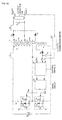
- Fig. 1 is the circuit diagram of the switching power supply according to the present embodiment.
- the first switch circuit S1 includes a first switching element Q1, a diode D1, and a capacitor C1
- the first switching element Q1 includes a FET, a drain terminal is connected to the primary winding np of the transformer T, and a source terminal is connected to the input power supply Vi.
- the diode D1 and the capacitor C1 are connected in parallel between the drain and the source of the first switching element Q1, and may be replaced with a parasitic diode and a parasitic capacitance of the first switching element Q1 that is an FET.
- the first switching element Q1 performs an on-off operation on the basis of a first switching control signal Vgs1 supplied from a control digital IC 10 through a drive circuit 103.
- a second switch circuit S2 and a capacitor Cr are connected so as to form a closed circuit with the primary winding np of the transformer T and the inductor Lr.
- the second switch circuit S2 includes a second switching element Q2 in which an FET is included, a diode D2, and a capacitor C2.
- the drain terminal of the second switching element Q2 is connected to the capacitor Cr, and the source terminal thereof is connected to the primary winding np of the transformer T.
- the diode D2 and the capacitor C2 are connected in parallel between the drain and the source of the second switching element Q2, and may be replaced with a parasitic diode and a parasitic capacitance of the second switching element Q2 that is an FET.
- the second switching element Q2 performs an on-off operation on the basis of a second switching control signal Vgs2 supplied from the control digital IC 10 through the drive circuit 103.
- a bias winding nb is disposed on the primary side of the transformer T, and one end portion of the bias winding nb is connected to the input power supply Vi.
- the anode of a diode D3 is connected to the other end portion of the bias winding nb.
- a capacitor C3 is connected to the cathode of the diode D3, According to this configuration, a rectification smoothing circuit is formed by the diode D3 and the capacitor C3, and a driving voltage Vcc for the control digital IC 10 is supplied to the control digital IC 10.
- connection side of the primary winding np of the transformer T with the first switch circuit S1 is connected to the control digital IC 10 through a resistor voltage-dividing circuit not illustrated, and a voltage level at the voltage dividing point of the resistor voltage-dividing circuit is supplied, as a monitor signal Vm, to the control digital IC 10.
- control digital IC 10 includes a DSP or an FPGA.
- the control digital IC 10 is driven using the above-mentioned driving voltage Vcc, and, on the basis of the monitor signal Vm and a detection voltage signal Vo obtained from the secondary side circuit of the transformer T, generates the first switching control signal Vgs1 used for driving the first switching element Q1 and the second switching control signal Vgs2 used for driving the second switching element Q2.
- the specific configuration and control of the control digital IC 10 will be described later.
- the drive circuit 103 includes a high-side driver IC or the like, and inputs and boosts the first switching control signal Vgs1 and the second switching control signal Vgs2 into signals whose levels can drive at least the second switching element Q2.
- the drive circuit 103 outputs the first switching control signal Vgs1 to the first switching element Q1 and outputs the second switching control signal Vgs2 to the second switching element Q2.
- a secondary winding ns1 of the transformer T is wound so as to have a reverse polarity with respect to the primary winding np, and both end portions of the secondary winding ns1 are voltage output terminals Vout(+) and Out(-).
- the anode of a diode Ds is connected to one end portion on a voltage output terminal Vout(+) side of the secondary winding ns1, and the cathode of the diode Ds is connected to the voltage output terminal Vout(+).
- a capacitor Co is connected between both terminals of the voltage output terminals Vout(+) and Volt(-). According to such a configuration as described above, a rectification smoothing circuit based on the diode Ds and the capacitor Co is formed.
- a voltage detection unit 101 including a series resistance circuit and the like is connected between both terminals of the voltage output terminals Vout(+) and Vout(-), generates a detection voltage signal Vo according to an output voltage level between the voltage output terminals Vout(-) and Vout(-), and outputs the detection voltage signal Vo to isolated transmission means 102.
- the isolated transmission means 102 includes a photo coupler or the like, and transmits, to the control digital IC 10 on the primary side, the detection voltage signal Vo generated in the voltage detection unit 101 on the secondary side.
- an isolated-type switching power supply based on a flyback method is configured.
- the control digital IC 10 includes a DSP, an FPGA, or the like, and generates the first switching control signal Vgs1 used for performing on-off control for the first switching element Q1 and the second switching control signal Vgs2 used for performing on-off control for the second switching element Q2 on the basis of the monitor signal Vm and the detection voltage signal Vo, which are input.
- the control digital IC 10 generates the first switching control signal Vgs1 and the second switching control signal Vgs2 with maintaining a constant switching period Ts so that a desired output voltage level is obtained and the first switching element Q1 and the second switching element Q2 are not simultaneously turned on.
- the generated first switching control signal Vgs1 and second switching control signal Vgs2 are output to the drive circuit 103.
- Fig. 2A is a circuit diagram illustrating the configuration of the internal block of the control digital IC 10 and Fig. 2B is the logical block diagram of a voltage compensation unit 132.
- the control digital TC 10 includes comparators 111 and 112, an ADC (analog-to-digital converter) 12, a CPU 13, and drive pulse generation units 141 and 142.
- the CPU 13 includes an adder 131, a voltage compensation unit 132, and a difference circuit 133,
- the comparator 121 compares the monitor signal Vm with a predetermined threshold value V1, and outputs a trigger signal that is of an Hi level during a time period when the monitor signal Vm is less than or equal to the threshold value V1 and is of a Low level during a time period when the monitor signal Vm is greater than the threshold value V1
- the comparator 122 compares the monitor signal Vm with a predetermined threshold value V2 (> the threshold value V1), and outputs a trigger signal that is of an Hi level during a time period when the monitor signal Vm is greater than or equal to the threshold value V2 and is of a Low level during a time period when the monitor signal Vm is less than the threshold value V2.
- the comparators 121 and 122 may also be formed separately from the control digital IC 10.
- the ADC 12 is an analog-to-digital converter, converts the detection voltage signal Vo from an analog signal into a digital signal, and outputs the digital signal to the adder 13. At this time, the ADC 12 uses, as a trigger, timings at which trigger signals from the comparators 121 and 122 transit from the Low level to the Hi level and starts analog-to-digital conversion. In addition, in the configuration of the present embodiment, it is only necessary for at least the trigger signal from the comparator 121 to be input, and in response to the start timing of the analog-to-digital conversion, it is only necessary to arbitrarily set which one of the trigger signals is used.
- the adder 131 calculates a difference voltage ev between the detection voltage signal Vo subjected to digital conversion and a reference voltage level Vref that is a desired voltage level, and supplies the difference voltage ev to the voltage compensation unit 132.
- the voltage compensation unit 132 includes such a PI controller as illustrated in Fig. 2B , and outputs a control value u1 indicating an on-time Ton1 of the first switching element Q1 on the basis of the difference voltage ev.
- the voltage compensation unit 132 supplies the control value u1 to the difference circuit 133 and the drive pulse generation unit 141.
- the difference circuit 133 calculates an on-time Ton2 of the second switching element Q2.
- the difference circuit 133 executes subtraction processing.
- these delay times TF1 and TF2 have extremely short time lengths as long as the individual switching elements Q1 and Q2 are not simultaneously turned on and a ZVS operation can be certainly performed, and these delay times TF1 and TF2 are preliminarily set as fixed values off-line
- the difference circuit 133 calculates the on-time Ton2 of the second switching element Q2.
- the difference circuit 133 supplies a control value u2 according to the calculated on-time Ton2 to the drive pulse generation unit 142,
- the drive pulse generation unit 141 includes a so-called digital PWM circuit, and uses, as a trigger, a timing at which the trigger signal from the comparator 121 transits to the Hi level, namely, a timing at which the level of the monitor signal Vm is decreased to reach the threshold value VI, and causes the first switching control signal Vgs1 to transit to the Hi level.
- the drive pulse generation unit 141 includes a counter counting up to a predetermined value during the time length of the switching period Ts, and continues counting with refreshing a counter value with respect to each switching period Ts. In addition, the timing of the refresh is caused to coincide with the timing at which the first switching control signal Vgs1 transits to the Hi level,
- the drive pulse generation unit 141 When having counted up to a count value corresponding to the given control value u1, the drive pulse generation unit 141 causes the first switching control signal Vgs1 to transit to the Low level. Accordingly, the drive pulse generation unit 141 can output the first switching control signal Vgs1 that is of the Hi level, during the desired on-time Ton1.
- the drive pulse generation unit 141 outputs the first switching control signal Vgs1 so that the timing at which the first switching control signal Vgs1 is caused to transit to the Hi level is caused to constantly coincide with the refresh timing of the counter, set on the basis of the switching period Ts as described above. Accordingly, the drive pulse generation unit 141 continuously outputs the first switching control signal Vgs1 with the predetermined constant switching period Ts.
- the drive pulse generation unit 142 also includes a so-called digital PWM circuit, and uses, as a trigger, a timing at which the trigger signal from the comparator 122 transits to the Hi level, namely, a timing at which the level of the monitor signal Vm is increased to reach the threshold value V2, and causes the second switching control signal Vgs2 to transit to the Hi level.
- the drive pulse generation unit 142 also includes a counter counting up, and continues counting with refreshing a counter value with respect to each switching period Ts. In addition, the timing of the refresh is caused to coincide with the timing at which the second switching control signal Vgs2 transits to the Hi level.
- the drive pulse generation unit 142 When having counted up to a count value corresponding to the given control value u2, the drive pulse generation unit 142 causes the second switching control signal Vgs2 to transit to the Low level. Accordingly, the drive pulse generation unit 142 can output the second switching control signal Vgs2 of the Hi level, during the on-time Ton2 nearly equal to a value obtained by subtracting the on-time Ton1 of the first switching element Q1 from the above-mentioned switching period Ts.
- Fig. 3 is a flowchart illustrating the switching control flow of the control digital IC 10.
- Fig. 4 is a waveform diagram illustrating a temporal relationship between the states of individual signals.
- the control digital IC 10 continuously detects the polarity of the transformer voltage Vt of the transformer T using the monitor signal Vm (S101), and detects the change of magnetic flux due to the rising of the transformer voltage Vt on the basis that the voltage level of the monitor signal Vm is decreased to reach the threshold value V1 (S102: Yes). At this time, by a time length from a time when the voltage level of the monitor signal Vm begins to be decreased to a time when the voltage level of the monitor signal Vm reaches the threshold value V1, a delay time TN1 occurs. This delay time TN1 is determined on the basis of a load state. In addition, since the control digital IC 10 does not detect polarity reversion until such a timing to, the control digital IC 10 continuously continues to detect the polarity of the transformer voltage Vt using the monitor signal Vm (S102: No ⁇ S101).
- the control digital IC 10 when the control digital IC 10 detects the change of magnetic flux of the transformer voltage Vt on the basis that the monitor signal Vm has reached the threshold value V1, the control digital IC 10 causes the first switching control signal Vgs1 to transit to the Hi level after a predetermined minute delay time TF1 (S103). Accordingly, the first switching control signal Vgs1 transits to the Hi level at a timing t2 that is positioned the extremely short delay time TF1 later after a timing at which it is detected that the monitor signal Vm has reached the threshold value V1
- the second switching control signal Vgs2 and the first switching control signal Vgs1 can be prevented from being simultaneously put into the Hi level, namely, the first switching element Q1 and the second switching element Q2 can be prevented from being simultaneously turned on.
- the threshold value V1 is set to a voltage nearly equal to the Low level of the monitor signal Vm, and hence, at a timing at which the first switching control signal Vgs1 is supplied to the switching element Q1, the drain-to-source voltage of the switching element Q1 becomes "0" electrical potential or about “0” electrical potential, and it is possible to realize zero-voltage switching (ZVS).
- the first switching control signal Vgs1 since a timing at which the first switching control signal Vgs1 transits to the Hi level is controlled using the threshold value V1, it is possible to cause the first switching control signal Vgs1 to transit to the Hi level at an optimum timing suited to a load situation. Furthermore, by providing the minute delay time TF1, it is possible to ensure more certain simultaneous turnon and the ZVS operation while maintaining an adequate timing,
- the control digital IC 10 clears the count value of a timer used for the first switching control signal Vgs1 and starts counting up.
- the control digital IC 10 A/D-converts the detection voltage signal Vo, and calculates a difference value ev with respect to the reference voltage level Vref supplying a desired voltage level (S103).
- the control digital IC 10 calculates the on-time Ton1 of the first switching control signal Vgs1, and calculates and determines the control value u1 giving the corresponding on-time Ton1 as a counter value.
- the control digital IC 10 calculates the on-time Ton2 of the second switching control signal Vgs2, and calculates and determines the control value u2 giving the corresponding on-time Ton2 as a counter value (S104').
- the corresponding subtraction processing is performed. Furthermore, taking some account of the delay time Tdead1 including the corresponding minute delay time TF1 and a delay time Tdead2 including the minute delay time TF2, the subtraction processing may be performed. In addition, since these delay times are extremely short for the on-times tond1 and Ton2 of the switching elements Q1 and Q2, practically, the nearly constant switching period Ts is maintained.
- a time length Tca1 necessary for calculating and determining such control values u1 and u2 is extremely short. Therefore, the determination timing Teal of the control values u1 and u2 when a timing at which the first switching control signal Vgs1 is caused to transit to the Hi level is regarded as a basing point becomes a timing (a timing t3 in Fig. 4 ) extremely earlier than a timing (a timing t4 in Fig. 4 ) at which the on-time Ton1 of the first switching control signal Vgs1, given by the control value u1, is terminated. Accordingly, it is possible to certainly set a timing at which the first switching control signal Vgs1 is caused to transit to the Low level,
- the control digital IC 10 When detecting that the count value of the timer used for the first switching control signal Vgs1 has reached the count value set by the control value u1, the control digital IC 10 causes the first switching control signal Vgs1 to transit to the Low level as illustrated with respect to the timing t4 in Fig. 4 (S105). Accordingly, the control digital IC 10 can supply the first switching control signal Vgs1 of the Hi level to the first switching element Q1 over the desired on-time Ton1,
- the control digital IC 10 detects polarity reversion due to the falling of the transformer voltage Vt on the basis that the voltage level of the monitor signal Vm is increased to reach the threshold value V2 (S106: Yes). At this time, by a time length from a time when the voltage level of the monitor signal Vm begins to be increased to a time when the voltage level of the monitor signal Vm reaches the threshold value V2, a delay time TN2 occurs. This delay time TN2 is determined on the basis of a load state. In addition, since the control digital IC 10 does not detect polarity reversion until such a timing t4, the control digital IC 10 continuously continue to detect the polarity of the transformer voltage Vt using the monitor signal Vm (S106: No).
- the control digital IC 10 when the control digital IC 10 detects the change of magnetic flux of the transformer voltage Vt on the basis that the monitor signal Vm has reached the threshold value V2, the control digital IC 10 causes the second switching control signal Vgs2 to transit to the Hi level after the predetermined minute delay time TF2 (S108). At this time, the second switching control signal Vgs2 transits to the Hi level at a timing t6 that is further positioned the extremely short delay time TF2 later after a timing at which it is detected that the monitor signal Vm has reached the threshold value V2,
- the first switching control signal Vgs1 and the second switching control signal Vgs2 can be prevented from being simultaneously put into the Hi level, namely, the first switching element Q1 and the second switching element Q2 can be prevented from being simultaneously turned on.
- the threshold value V2 is set to a voltage nearly equal to the Hi level of the monitor signal Vm, and hence, at a timing at which the second switching control signal Vgs2 is supplied to the switching element Q2, the drain-to-source voltage of the switching element Q2 becomes "0" electrical potential or about “0” electrical potential, and it is possible to realize the zero-voltage switching (ZVS).
- the second switching control signal Vgs2 since a timing at which the second switching control signal Vgs2 transits to the Hi level is controlled using the threshold value V2, it is possible to cause the second switching control signal Vgs2 to transit to the Hi level at an optimum timing suited to a load situation. Furthermore, by providing the minute delay time TF2, it is possible to ensure more certain simultaneous turnon and the ZVS operation while maintaining an adequate timing.
- the control digital IC 10 clears the count value of a timer used for the second switching control signal Vgs2 and starts counting up.
- the control digital IC 10 when detecting that the count value of the timer used for the second switching control signal Vgs2 has reached the count value set by the control value u2 calculated for the above-mentioned time period Tp3, the control digital IC 10 causes the second switching control signal Vgs2 to transit to the Low level (S108). Accordingly, the control digital IC 10 can supply the second switching control signal Vgs2 of the Hi level to the second switching element Q2 over the on-time Ton2 arbitrarily set on the basis of the constant switching period Ts and the on-time Ton1 of the first switching control signal Vgs1.
- the configuration and processing of the present embodiment it is possible to set the on-time Ton1 of the first switching control signal Vgs1 so as to obtain a desired output voltage, and it is possible to prevent the on-time Ton1 of the corresponding first switching control signal Vgs1 and the on-time Ton2 of the second switching control signal Vgs2 from overlapping each other on a time axis. Accordingly, it is possible to prevent the damage of a switching element due to a short circuit from occurring and it is possible to realize a switching power supply having a high degree of reliability.
- the delay times Tdead1 and Tdead2 include the minute delay times TF1 and TF2 and are set to adequate values suited to a load situation on the basis of the change of magnetic flux of the transformer voltage Vt so that the on-times Ton1 and Torn2 are spaced from each other on the time axis. Therefore, it is possible to realize a switching power supply having a high degree of efficiency.
- the switching period Ts is controlled so as to be constant, it is possible to easily deal with a noise due to the switching period Ts and it is possible to realize a switching power supply having low EMI.
- a circuit configuration may be adopted in which the capacitor Cr is connected in series to the input power supply Vi, as illustrated in Fig. 5.
- Fig. 5 is the circuit diagram of a switching power supply including another circuit configuration illustrated in the first embodiment. Even in such a configuration, it is possible to apply the above-mentioned switching control, and it is possible to obtain the same function effect.
- Fig, 6 is the circuit diagram of the switching power supply according to the present embodiment.
- the primary winding np and the secondary winding ns1 of the transformer T are wound so as to have a same polarity.
- a circuit pattern on the primary side of the transformer T and the isolated transmission means 102 are the same as those in the above-mentioned switching power supply illustrated in Fig. 1 , and a circuit pattern on a secondary side is different from that in the above-mentioned switching power supply illustrated in Fig. 1 .
- the anode of the diode Ds is connected to one end portion of the secondary winding ns1 of the switching power supply according to the present embodiment, and the cathode of the corresponding diode Ds is connected to the voltage output terminal Vout(+) through an inductor Lo.
- the other end portion of the secondary winding ns1 is connected to the voltage output terminal Vout(-).
- a diode Df is connected in parallel between both terminals of the secondary winding ns1. At this time, the cathode of the diode Df is connected to the inductor Lo functioning as a filter inductor.
- the capacitor Co is connected between both terminals of the voltage output terminals Vout(+) and Vout( ).
- a rectification smoothing circuit based on the diodes Ds and Df, the inductor Lo, and the capacitor Co is formed.
- a voltage detection unit 101 including a series resistance circuit and the like is connected between both terminals of the voltage output terminals Vout(+) and Vout(-), generates a detection voltage signal Vo according to an output voltage level between both terminals of the voltage output terminals Vout(+) and Vout(-), and outputs the detection voltage signal Vo to the isolated transmission means 102.
- an isolated-type switching power supply based on a forward method is configured.
- Fig. 7 is the circuit diagram of the switching power supply according to the present embodiment.
- a circuit pattern on the primary side of the transformer T and the isolated transmission means 102 are the same as those in the above-mentioned switching power supply illustrated in Fig. 1 , and the transformer T and a circuit pattern on the secondary side thereof are different from those in the above-mentioned switching power supply illustrated in Fig. 1 .
- the transformer T is a composite-type transformer in which two secondary windings ns1 and ns2 are disposed with respect to one primary winding np.
- the first secondary winding ns1 of the transformer T is wound with the polarity thereof being opposite to the primary winding np, and the second secondary winding ns2 is wound with the polarity thereof being the same as the primary winding np.
- the voltage output terminal Vout(+) is connected to one end portion of the first secondary winding ns1 through the inductor Lo.
- the cathode of the diode Ds is connected to the other end portion of the first secondary winding ns1, and the anode of the corresponding diode Ds is connected to the voltage output terminal Vout(-).
- One end portion of the second secondary winding ns2 is connected to the other end portion of the first secondary winding ns1.
- the cathode of the diode Df is connected to one end portion of the second secondary winding ns2, and the anode of the corresponding diode Df is also connected to the voltage output terminal Vout(-).
- a capacitor Co is connected between both terminals of the voltage output terminals Vout(+) and Vout(-).
- a rectification smoothing circuit based on the diodes Ds and Df, the inductor Lo, and the capacitor Co is formed.
- a voltage detection unit 101 including a series resistance circuit and the like is connected between both terminals of the voltage output terminals vout(+) and Vout(-), generates a detection voltage signal Vo according to an output voltage level between both terminals of the voltage output terminals Vout(+) and Vout(-), and outputs the detection voltage signal Vo to the isolated transmission means 102,
- a current flows through a loop such as the voltage output terminal Vout(-) ⁇ the diode Df ⁇ the second secondary winding ns2 ⁇ the first secondary winding ns1 ⁇ the inductor Lo ⁇ the voltage output terminal Vout(+), and for a time period when the first switch circuit S1 is turned off and the second switch circuit S2 is turned on, a current flows through a loop such as the voltage output terminal Vout(-) ⁇ the diode Ds ⁇ the first secondary winding ns1 the inductor Lo ⁇ the voltage output terminal Vout (+) Therefore, for any one of the on-period of the first switch circuit S1 (the off-period of the second switch circuit S2) and the off-period of the first switch circuit S1 (the on-period of the second switch circuit S2), it is possible to perform energy transmission from the
- the delay times Tdead1 and Tdead2 are optimized by applying the above-mentioned switching control. Therefore, it is possible to very efficiently perform energy transmission over almost the entire time period of the switching period Ts.
- a circuit configuration may be adopted in which the capacitor Cr is connected in series to the input power supply Vi, as illustrated in Fig. 8.
- Fig. 8 is the circuit diagram of a switching power supply including another circuit configuration illustrated in the third embodiment.
- a circuit configuration may be adopted in which a series circuit including the second switch circuit S2 and the capacitor Cr is connected in parallel to the first switch circuit S1.
- Fig. 9 is the circuit diagram of a switching power supply including another circuit configuration illustrated in the third embodiment. Even in such a configuration, it is possible to apply the above-mentioned switching control, and it is possible to obtain the same function effect.
- Fig. 10 is the circuit diagram of a switching power supply according to the present embodiment.
- a circuit pattern on the primary side of the transformer T and the isolated transmission means 102 are the same as those in the above-mentioned switching power supply illustrated in Fig. 1 , and the transformer T and a circuit pattern on a secondary side are different from those in the above-mentioned switching power supply illustrated in Fig. 1 .
- the transformer T is a composite-type transformer in which two secondary windings ns1 and ns2 are disposed with respect to one primary winding np.
- the first secondary winding ns1 of the transformer T is wound with the polarity thereof being the same as the primary winding np, and the second secondary winding ns2 is also wound with the polarity thereof being the same as the primary winding np.
- the anode of the diode Ds is connected to one end portion of the first secondary winding ns1, and the cathode of the corresponding diode Ds is connected to the voltage output terminal Vout(+) through the inductor Lo.
- the other end portion of the first secondary winding ns1 is connected to the voltage output terminal Vout(-).
- One end portion of the second secondary winding ns2 is connected to the other end portion of the first secondary winding ns1.
- the cathode of the diode Df is connected to the other end portion of the second secondary winding ns2, and the anode of the corresponding diode Df is also connected to the voltage output terminal Vout(+) through the inductor Lo.
- a capacitor Co is connected between both terminals of the voltage output terminals Vout(+) and Vout(-).
- a rectification smoothing circuit based on the diodes Ds and Df, the inductor Lo, and the capacitor Co is formed.
- a voltage detection unit 101 including a series resistance circuit and the like is connected between both terminals of the voltage output terminals Vout(+) and Vout(-), generates a detection voltage signal Vo according to an output voltage level between both terminals of the voltage output terminals Vout(+) and Vout(-), and outputs the detection voltage signal Vo to the isolated transmission means 102.
- a circuit configuration may be adopted in which the capacitor Cr is connected in series to the input power supply Vi, as illustrated in Fig. 11.
- Fig. 11 is the circuit diagram of a switching power supply including another circuit configuration illustrated in the fourth embodiment.
- a circuit configuration may be adopted in which a series circuit including the second switch circuit S2 and the capacitor Cr is connected in parallel to the first switch circuit S1.
- Fig. 12 is the circuit diagram of a switching power supply including another circuit configuration illustrated in the fourth embodiment. Even in such a configuration, it is possible to apply the above-mentioned switching control, and it is possible to obtain the same function effect
- Fig. 13 is the circuit diagram of a switching power supply according to the present embodiment.
- the transformer T, a circuit pattern on the secondary side of the transformer T, and the isolated transmission means 102 are the same as those in the switching power supply illustrated in Fig. 10 in the above-mentioned fourth embodiment, and a configuration is included in which the bias winding nb on the primary side is not disposed.
- a current transformer circuit 104 is formed whose primary winding is the inductor Lr connected in series to the primary winding np.
- a resistance element R is connected to the secondary winding of the current transformer circuit 104, and one end portion of the corresponding resistance element R is connected to the anode of the diode D3.
- the cathode of the corresponding diode D3 is connected to the switch control digital IC 10, and hence the monitor signal Vm is supplied to the control digital IC 10
- Fig. 14 is the circuit diagram of a switching power supply according to the present embodiments.
- the transformer T, a circuit pattern on the secondary side of the transformer T, and the isolated transmission means 102 are the same as those in the switching power supply including a configuration in which the bias winding nb on the primary side is not disposed, illustrated in Fig. 13 in the above-mentioned fifth embodiment.
- the switching power supply of the present embodiment does not use the current transformer circuit illustrated in Fig. 13 in the above-mentioned fifth embodiment. Therefore, the switching power supply of the present embodiment obtains the monitor signal Vm from one end portion of the primary winding np through a resistor voltage-dividing circuit, in the same way as in the above-mentioned first embodiment
- Fig. 15 is the circuit diagram of a switching power supply according to the present embodiment. While, in each of the above-mentioned embodiments, the isolated-type switching power supply utilizing the transformer T has been illustrated as an example, in the present embodiment, a case in which the above-mentioned switching control is applied to an non-isolated-type converter will be described as an example.
- the voltage output terminal Vout(-) is connected to one end portion (Vi(+)) of the input power supply Vi, to which the direct-current input voltage is applied.
- the other end portion (Vi(-)) of the input power supply Vi is connected to the voltage output terminal Vout(+) through a series circuit including the first switch circuit Q1 and the diode Ds.
- An inductor Lp is connected on an input power supply Vi side with respect to the diode Ds between both terminals of the voltage output terminals Vout(+) and Vout,(-), and furthermore, the capacitor Co is connected on voltage output terminals Vout(+) and Vout(-) sides with respect to the diode Ds.
- a series circuit including the capacitor Cr and the second switch circuit S2 is connected in parallel to the inductor Lp on an input power supply Vi side of the inductor Lp.
- the first switch circuit S1 includes the first switching element Q1 in which an FET is included, the diode D1, and the capacitor C1.
- the diode D1 and the capacitor C1 are connected in parallel between the drain and the source of the first switching element Q1, and may be replaced with a parasitic diode and a parasitic capacitance of the first switching element Q1 that is an FET.
- the first switching element Q1 performs an on-off operation on the basis of the first switching control signal Vgs1 supplied from the control digital IC 10 through the drive circuit 103.
- the second switch circuit S2 includes the second switching element Q2 in which an FET is included, the capacitor C2, and the diode D2.
- the diode D2 and the capacitor C2 are connected in parallel between the drain and the source of the second switching element Q2, and may be replaced with a parasitic diode and a parasitic capacitance of the second switching element Q2 that is an FET.
- the second switching element Q2 performs an on-off operation on the basis of the second switching control signal Vgs2 supplied from the control digital IC 10 through the drive circuit 103.
- the voltage detection unit 101 including a series resistance circuit and the like is connected between both terminals of the voltage output terminals Vout(+) and Vout(-).
- the voltage detection unit 101 generates the detection voltage signal Vo according to an output voltage level between both terminals of the voltage output terminals Vout(+) and Vout(-), and supplies the detection voltage signal Vo to the control digital IC 10.
- the output voltage between the voltage output terminals Vout(+) and Vout(-) is supplied to the control digital IC 10, as the driving voltage Vcc of the control digital IC 10
- control digital IC 10 is driven using the driving voltage Vcc, and, on the basis of the monitor signal Vm and the detection voltage signal Vo from the voltage detection unit 101, generates the first switching control signal Vgs1 and the second switching control signal Vgs2 so that the output voltage is controlled to become a predetermined voltage level.
- the drive circuit 103 inputs and boosts the first switching control signal Vgs1 and the second switching control signal Vgs2 into signals whose levels can drive at least the second switching element Q2.
- the drive circuit 103 outputs the first switching control signal Vgs1 to the first switching element Q1 and outputs the second switching control signal Vgs2 to the second switching element Q2,
- Fig. 16 is the circuit diagram of a switching power supply according to the present embodiment.
- the present embodiment in the same way as the switching power supply illustrated in the seventh embodiment, a case in which the above-mentioned switching control is applied to a non-isolated-type converter will be described as an example.
- the voltage output terminal Vout(+) is connected to one end portion (Vi(+)) of the input power supply Vi, to which the direct-current input voltage is applied, through a series circuit including the second switch circuit Q2 and the inductor Lp.
- the other end portion (vi(-)) of the input power supply Vi is connected to the voltage output terminal Vout(-)
- the second switch circuit S2 includes the second switching element Q2 in which an FET is included, the diode D2, and the capacitor C2.
- the diode D2 and the capacitor C2 are connected in parallel between the drain and the source of the second switching element Q2, and may be replaced with a parasitic diode and a parasitic capacitance of the second switching element Q2 that is an FET.
- the second switching element Q2 performs an on-off operation on the basis of the second switching control signal Vgs2 supplied from the control digital IC 10 through the drive circuit 103.
- the first switch circuit S1 is connected between a connection point between the second switch circuit S2 and the inductor Lp and the voltage output terminal Vout(-)
- the first switch circuit S1 includes the first switching element Q1 in which an FET is included, the diode D1, and the capacitor C1.
- the diode D1 and the capacitor C1 are connected in parallel between the drain and the source of the first switching element Q1, and may be replaced with a parasitic diode and a parasitic capacitance of the first switching element Q1 that is an FET.
- the first switching element Q1 performs an on-off operation on the basis of the first switching control signal Vgs1 supplied from the control digital IC 10 through the drive circuit 103
- the capacitor Co is connected on voltage output terminals Vout(+) and vout(-) sides with respect to the inductor Lp between both terminals of the voltage output terminals Vout(+) and Vout(-)
- the voltage detection unit 101 including a series resistance circuit and the like is connected between both terminals of the voltage output terminals Vout(+) and Vout(-).
- the voltage detection unit 101 generates the detection voltage signal Vo according to an output voltage level between both terminals of the voltage output terminals Vout(+) and Vout(-), and outputs the detection voltage signal Vo to the control digital IC 10.
- the output voltage between the voltage output terminals Vout(+) and Vout(-) is supplied to the control digital IC 10, as the driving voltage Vcc of the control digital IC 10.
- control digital IC 10 is driven using the driving voltage Vcc, and, on the basis of a first monitor signal Vm1, a second monitor signal Vm2, and the detection voltage signal Vo from the voltage detection unit 101, generates the first switching control signal Vgs1 and the second switching control signal Vgs2 so that the output voltage is controlled to become a predetermined voltage level
- the drive circuit 103 inputs and boosts the first switching control signal Vgs1 and the second switching control signal Vgs2 into signals whose levels can drive at least the second switching element Q2.
- the drive circuit 103 outputs the first switching control signal Vgs1 to the first switching element Q1 and outputs the second switching control signal Vgs2 to the second switching element Q2
- Fig. 17 is the circuit diagram of a switching power supply according to the present embodiment.
- the switching power supply according to the present embodiment corresponds to a switching power supply in which the diode Ds on the secondary side is replaced with a switching element Qs in the flyback-method switching power supply illustrated in Fig. 1 in the first embodiment.
- the control digital IC 10 also generates a switch control signal Vgss for the switching element Qs in addition to the first switching element Q1 of the first switch circuit S1 and the second switching element Q2 of the second switch circuit S2.
- the control digital IC 10 generates the switch control signal Vgss so that the switching element Qs operates in the same way as the diode Ds illustrated in the first embodiment.
- the switch control signal Vgss generated in the control digital IC 10 is supplied to the switching element Qs through second isolated transmission means 102'.
- the switch control signal Vgss is supplied to the switching element Qs.
- a circuit configuration may also be adopted in which the capacitor Cr is connected in series to the input power supply Vi, as illustrated in Fig. 18
- Fig. 18 is the circuit diagram of a switching power supply including another circuit configuration illustrated in the ninth embodiment.
- Fig. 19 is the circuit diagram of a switching power supply according to the present embodiment.
- the switching power supply according to the present embodiment corresponds to a switching power supply in which the diode Ds on the secondary side is replaced with a switching element Qs and the diode Df is replaced with a switching element Qf in the forward-method switching power supply illustrated in Fig. 6 in the second embodiment.
- the switching element Qs corresponding to a rectification-side synchronous rectifying element and the switching element Qf corresponding to a commutation-side synchronous rectifying element configure a self-driven synchronous rectifying circuit in which on-off operations are complementarily performed in response to the change of magnetic flux in the secondary winding ns of the transformer T.
- Fig. 20 is the circuit diagram of a switching power supply according to the present embodiment.
- the switching power supply according to the present embodiment corresponds to a switching power supply in which the diode Ds on the secondary side is replaced with the switching element Qs and the diode Df is replaced with the switching element Qf in the switching power supply illustrated in Fig. 7 in the third embodiment.
- the control digital IC 10 also generates a switch control signal Vgss for the switching element Qs and a switch control signal Vgsf for the switching element Qf in addition to the first switching element Q1 of the first switch circuit S1 and the second switching element Q2 of the second switch circuit S2.
- the control digital IC 10 generates the switch control signal Vgss so that the switching element Qs operates in the same way as the diode Ds illustrated in the first embodiment.
- the control digital IC 10 generates the switch control signal Vgsf so that the switching element Qf operates in the same way as the diode Df illustrated in the first embodiment.
- the switch control signals Vgss and Vgsf generated in the control digital IC 10 are supplied to the switching elements Qs and Qf through the second isolated transmission means 102'.
- the switch control signals Vgss and Vgsf are supplied to the switching elements Qs and Qf.
- a circuit configuration may also be adopted in which the capacitor Cr is connected in series to the input power supply Vi, as illustrated in Fig. 21.
- Fig. 21 is the circuit diagram of a switching power supply including another circuit configuration illustrated in the eleventh embodiment.
- Fig. 22 is the circuit diagram of a switching power supply according to the present embodiment.
- the switching power supply according to the present embodiment corresponds to a switching power supply in which the diode Ds on the secondary side is replaced with the switching element Qs and the diode Df is replaced with the switching element Qf in the switching power supply including the center tap-type full-wave rectifier circuit, illustrated in Fig. 10 in the fourth embodiment.
- the control digital IC 10 also generates the switch control signal Vgss for the switching element Qs and the switch control signal Vgsf for the switching element Qf in addition to the first switching element Q1 of the first switch circuit S1 and the second switching element Q2 of the second switch circuit S2. At this time, the control digital IC 10 generates the switch control signal Vgss so that the switching element Qs operates in the same way as the diode Ds illustrated in the first embodiment. In addition, the control digital IC 10 generates the switch control signal Vgsf so that the switching element Qf operates in the same way as the diode Df illustrated in the first embodiment.
- the switch control signals Vgss and Vgsf generated in the control digital IC 10 are supplied to the switching elements Qs and Of through the second isolated transmission means 102'.
- the switch control signals Vgss and Vgsf are supplied to the switching elements Qs and Qf
- a circuit configuration may also be adopted in which the capacitor Cr is connected in series to the input power supply Vi, as illustrated in Fig. 23.
- Fig. 23 is the circuit diagram of a switching power supply including another circuit configuration illustrated in the twelfth embodiment
- Fig. 24 is the circuit diagram of a switching power supply according to the present embodiment.
- the switching power supply according to the present embodiment corresponds to a switching power supply in which the diode Ds on the primary side is replaced with the switching element Qs in the non-isolated-type buck-boost converter illustrated in Fig. 15 in the seventh embodiment
- the control digital IC 10 also generates the switch control signal Vgss for the switching element Qs in addition to the first switching element Q1 of the first switch circuit S1 and the second switching element Q2 of the second switch circuit S2. At this time, the control digital IC 10 generates the switch control signal Vgss so that the switching element Qs operates in the same way as the diode Ds illustrated in the seventh embodiment. In this way, the switch control signal Vgss generated in the control digital IC 10 is supplied to the switching element Qs. In addition, in the same way as the first switching control signal Vgs1 and the second switching control signal Vgs2, after being boosted by a drive circuit or the like as necessary, the switch control signal Vgss is supplied to the switching element Qs.
- a Hall sensor may also be provided in the transmission line connecting the switching element Q1 and the switching element side of the primary winding np to each other, and an output from the corresponding Hall sensor may also be used an monitor signal for example, in the configuration of the primary side circuit of the first embodiment. Accordingly, it is also possible to generate a monitor signal based on the change of a current flowing through the switching element
- a monitor signal may also be set with respect to each switching control signal and a threshold value may also be set for each monitor signal.
- an output from the bias winding may also be used as a monitor signal.
Applications Claiming Priority (2)
| Application Number | Priority Date | Filing Date | Title |
|---|---|---|---|
| JP2009098182 | 2009-04-14 | ||
| PCT/JP2010/055339 WO2010119760A1 (ja) | 2009-04-14 | 2010-03-26 | スイッチング電源装置 |
Publications (3)
| Publication Number | Publication Date |
|---|---|
| EP2421136A1 true EP2421136A1 (de) | 2012-02-22 |
| EP2421136A4 EP2421136A4 (de) | 2017-04-12 |
| EP2421136B1 EP2421136B1 (de) | 2019-05-08 |
Family
ID=42982425
Family Applications (1)
| Application Number | Title | Priority Date | Filing Date |
|---|---|---|---|
| EP10764345.4A Active EP2421136B1 (de) | 2009-04-14 | 2010-03-26 | Schaltnetzteileinheit |
Country Status (5)
| Country | Link |
|---|---|
| US (1) | US8582326B2 (de) |
| EP (1) | EP2421136B1 (de) |
| JP (1) | JP5447506B2 (de) |
| CN (1) | CN102396139B (de) |
| WO (1) | WO2010119760A1 (de) |
Families Citing this family (16)
| Publication number | Priority date | Publication date | Assignee | Title |
|---|---|---|---|---|
| JP2013153620A (ja) * | 2012-01-26 | 2013-08-08 | Fuji Electric Co Ltd | スイッチング電源装置 |
| CN103718446B (zh) * | 2011-08-11 | 2017-03-29 | 株式会社村田制作所 | 开关电源装置 |
| JP5987586B2 (ja) * | 2012-09-20 | 2016-09-07 | 富士電機株式会社 | スイッチング電源装置 |
| TWI525975B (zh) * | 2013-02-18 | 2016-03-11 | 崇貿科技股份有限公司 | 返馳式功率轉換器之控制電路 |
| JP5642224B2 (ja) * | 2013-04-09 | 2014-12-17 | 三菱電機株式会社 | 車両用電源装置 |
| US9276483B2 (en) * | 2013-06-27 | 2016-03-01 | System General Corporation | Control circuit for active-clamp flyback power converter with programmable switching period |
| JP6402474B2 (ja) * | 2013-07-17 | 2018-10-10 | 富士電機株式会社 | スイッチング電源の制御装置 |
| TWI565211B (zh) | 2014-09-12 | 2017-01-01 | Alpha And Omega Semiconductor (Cayman) Ltd | Constant on-time switching converter means |
| TWI581555B (zh) | 2014-09-12 | 2017-05-01 | Alpha And Omega Semiconductor (Cayman) Ltd | 固定導通時間切換式轉換裝置 |
| TWI549412B (zh) * | 2014-09-12 | 2016-09-11 | Alpha & Omega Semiconductor Cayman Ltd | Fixed on-time switching type switching device |
| TWI556563B (zh) | 2014-09-12 | 2016-11-01 | Alpha & Omega Semiconductor Cayman Ltd | Fixed on-time switching type switching device |
| TWI574499B (zh) | 2014-09-12 | 2017-03-11 | Alpha And Omega Semiconductor (Cayman) Ltd | Fixed on-time switching type switching device |
| JP6665573B2 (ja) * | 2016-02-17 | 2020-03-13 | 富士電機株式会社 | スイッチング電源装置 |
| CN107390578A (zh) * | 2017-07-25 | 2017-11-24 | 环球智达科技(北京)有限公司 | 显示设备的感应控制方法 |
| CN109698629A (zh) * | 2019-01-07 | 2019-04-30 | 上海奥令科电子科技有限公司 | 一种大功率直流电源 |
| CN111525802B (zh) * | 2019-02-01 | 2021-08-06 | 台达电子工业股份有限公司 | 变换装置 |
Family Cites Families (24)
| Publication number | Priority date | Publication date | Assignee | Title |
|---|---|---|---|---|
| SE8605266L (sv) * | 1986-12-09 | 1988-06-10 | Ragnar Jonsson | Switch-koppling |
| JP2526754Y2 (ja) * | 1990-11-15 | 1997-02-19 | 株式会社電設 | インバータ駆動回路 |
| JPH05252795A (ja) | 1992-03-04 | 1993-09-28 | Toshiba Corp | インバータのデジタル電流制御装置 |
| US5430633A (en) * | 1993-09-14 | 1995-07-04 | Astec International, Ltd. | Multi-resonant clamped flyback converter |
| US5736842A (en) * | 1996-07-11 | 1998-04-07 | Delta Electronics, Inc. | Technique for reducing rectifier reverse-recovery-related losses in high-voltage high power converters |
| US5808879A (en) * | 1996-12-26 | 1998-09-15 | Philips Electronics North America Corporatin | Half-bridge zero-voltage-switched PWM flyback DC/DC converter |
| JP2000116147A (ja) * | 1998-07-27 | 2000-04-21 | Toshiba Lighting & Technology Corp | 電源装置、放電灯点灯装置および照明装置 |
| JP2000069746A (ja) * | 1998-08-21 | 2000-03-03 | Fujitsu Ltd | Dc−dcコンバータの制御方法、dc−dcコンバータの制御回路、及び、dc−dcコンバータ |
| JP3387456B2 (ja) | 1998-10-29 | 2003-03-17 | 株式会社村田製作所 | スイッチング電源装置 |
| JP2001258269A (ja) * | 2000-03-15 | 2001-09-21 | Kawasaki Steel Corp | ソフトスイッチングdc−dcコンバータ |
| JP2001258569A (ja) * | 2000-03-17 | 2001-09-25 | Tosoh Corp | 腸炎ビブリオ菌検出のためのオリゴヌクレオチド |
| US6562955B2 (en) | 2000-03-17 | 2003-05-13 | Tosoh Corporation | Oligonucleotides for detection of Vibrio parahaemolyticus and detection method for Vibrio parahaemolyticus using the same oligonucleotides |
| US6466462B2 (en) | 2000-10-31 | 2002-10-15 | Yokogawa Electric Corporation | DC/DC converter having a control circuit to reduce losses at light loads |
| JP4423458B2 (ja) * | 2000-11-10 | 2010-03-03 | 富士電機システムズ株式会社 | Dc/dcコンバータの制御方法 |
| JP3711555B2 (ja) * | 2001-04-19 | 2005-11-02 | 横河電機株式会社 | Dc/dcコンバータ |
| JP3740385B2 (ja) | 2001-06-04 | 2006-02-01 | Tdk株式会社 | スイッチング電源装置 |
| US20030179592A1 (en) * | 2002-03-25 | 2003-09-25 | Yokogawa Electric Corporation | DC/DC converter and method for controlling same |
| JP2004312913A (ja) * | 2003-04-09 | 2004-11-04 | Fuji Electric Device Technology Co Ltd | 降圧型dc−dcコンバータ |
| JP2005184964A (ja) * | 2003-12-18 | 2005-07-07 | Renesas Technology Corp | 電源装置及びその制御方法 |
| JP4238872B2 (ja) | 2004-02-03 | 2009-03-18 | 株式会社村田製作所 | スイッチング電源装置 |
| JP4835087B2 (ja) * | 2005-09-30 | 2011-12-14 | サンケン電気株式会社 | Dc−dcコンバータ |
| JP4345839B2 (ja) * | 2007-04-16 | 2009-10-14 | 株式会社デンソー | 電力変換装置 |
| US7787263B2 (en) * | 2007-05-18 | 2010-08-31 | Texas Instruments Incorporated | Methods and apparatus to control a digital power supply |
| US7924579B2 (en) * | 2008-02-05 | 2011-04-12 | Cisco Technology, Inc. | Fly-forward converter power supply |
-
2010
- 2010-03-26 EP EP10764345.4A patent/EP2421136B1/de active Active
- 2010-03-26 JP JP2011509251A patent/JP5447506B2/ja not_active Expired - Fee Related
- 2010-03-26 CN CN201080016323.XA patent/CN102396139B/zh not_active Expired - Fee Related
- 2010-03-26 WO PCT/JP2010/055339 patent/WO2010119760A1/ja active Application Filing
-
2011
- 2011-10-13 US US13/272,387 patent/US8582326B2/en not_active Expired - Fee Related
Non-Patent Citations (1)
| Title |
|---|
| See references of WO2010119760A1 * |
Also Published As
| Publication number | Publication date |
|---|---|
| US20120033454A1 (en) | 2012-02-09 |
| EP2421136A4 (de) | 2017-04-12 |
| US8582326B2 (en) | 2013-11-12 |
| CN102396139B (zh) | 2015-11-25 |
| JP5447506B2 (ja) | 2014-03-19 |
| EP2421136B1 (de) | 2019-05-08 |
| JPWO2010119760A1 (ja) | 2012-10-22 |
| WO2010119760A1 (ja) | 2010-10-21 |
| CN102396139A (zh) | 2012-03-28 |
Similar Documents
| Publication | Publication Date | Title |
|---|---|---|
| EP2421136B1 (de) | Schaltnetzteileinheit | |
| EP2421137B1 (de) | Schaltnetzteileinheit | |
| US10250152B2 (en) | Forced zero voltage switching flyback converter | |
| US9899931B1 (en) | Zero voltage switching flyback converter for primary switch turn-off transitions | |
| US10158282B1 (en) | Switching power supply device | |
| EP3198710B1 (de) | Steuerungsverfahren für aufwärts-abwärts-wandler | |
| US8520414B2 (en) | Controller for a power converter | |
| US11870350B2 (en) | Switched-mode power controller with multi-mode startup | |
| US9136768B2 (en) | Switching power supply device | |
| US9935547B2 (en) | System and method for a switched-mode power supply | |
| EP3664295B1 (de) | Zweistufiger schaltertreiber zur verhinderung des lawinendurchbruchs für einen synchronen gleichrichterschalter in einem leistungswandler, der in einem low-power-burst-modus betrieben wird | |
| WO2014034529A1 (ja) | スイッチング電源装置 | |
| WO2021176319A1 (en) | Auto-tuned synchronous rectifier controller | |
| US20120014149A1 (en) | Power conversion apparatus and method | |
| US8503195B1 (en) | System and method for zero volt switching of half bridge converters during startup and short circuit conditions | |
| Tong et al. | Research on a high output current DC/DC converter with wide input voltage range for space applications | |
| WO2019113893A1 (en) | Control circuits for driving power switches of isolated forward converters | |
| KR20030096823A (ko) | 푸시풀-플라이백 컨버터 |
Legal Events
| Date | Code | Title | Description |
|---|---|---|---|
| PUAI | Public reference made under article 153(3) epc to a published international application that has entered the european phase |
Free format text: ORIGINAL CODE: 0009012 |
|
| 17P | Request for examination filed |
Effective date: 20110927 |
|
| AK | Designated contracting states |
Kind code of ref document: A1 Designated state(s): AT BE BG CH CY CZ DE DK EE ES FI FR GB GR HR HU IE IS IT LI LT LU LV MC MK MT NL NO PL PT RO SE SI SK SM TR |
|
| DAX | Request for extension of the european patent (deleted) | ||
| RA4 | Supplementary search report drawn up and despatched (corrected) |
Effective date: 20170310 |
|
| RIC1 | Information provided on ipc code assigned before grant |
Ipc: H02M 3/155 20060101ALI20170306BHEP Ipc: H02M 3/28 20060101AFI20170306BHEP |
|
| GRAP | Despatch of communication of intention to grant a patent |
Free format text: ORIGINAL CODE: EPIDOSNIGR1 |
|
| STAA | Information on the status of an ep patent application or granted ep patent |
Free format text: STATUS: GRANT OF PATENT IS INTENDED |
|
| INTG | Intention to grant announced |
Effective date: 20181022 |
|
| GRAS | Grant fee paid |
Free format text: ORIGINAL CODE: EPIDOSNIGR3 |
|
| GRAA | (expected) grant |
Free format text: ORIGINAL CODE: 0009210 |
|
| STAA | Information on the status of an ep patent application or granted ep patent |
Free format text: STATUS: THE PATENT HAS BEEN GRANTED |
|
| AK | Designated contracting states |
Kind code of ref document: B1 Designated state(s): AT BE BG CH CY CZ DE DK EE ES FI FR GB GR HR HU IE IS IT LI LT LU LV MC MK MT NL NO PL PT RO SE SI SK SM TR |
|
| REG | Reference to a national code |
Ref country code: GB Ref legal event code: FG4D |
|
| REG | Reference to a national code |
Ref country code: CH Ref legal event code: EP Ref country code: AT Ref legal event code: REF Ref document number: 1131755 Country of ref document: AT Kind code of ref document: T Effective date: 20190515 |
|
| REG | Reference to a national code |
Ref country code: DE Ref legal event code: R096 Ref document number: 602010058767 Country of ref document: DE Ref country code: IE Ref legal event code: FG4D |
|
| REG | Reference to a national code |
Ref country code: NL Ref legal event code: MP Effective date: 20190508 |
|
| REG | Reference to a national code |
Ref country code: LT Ref legal event code: MG4D |
|
| PG25 | Lapsed in a contracting state [announced via postgrant information from national office to epo] |
Ref country code: ES Free format text: LAPSE BECAUSE OF FAILURE TO SUBMIT A TRANSLATION OF THE DESCRIPTION OR TO PAY THE FEE WITHIN THE PRESCRIBED TIME-LIMIT Effective date: 20190508 Ref country code: SE Free format text: LAPSE BECAUSE OF FAILURE TO SUBMIT A TRANSLATION OF THE DESCRIPTION OR TO PAY THE FEE WITHIN THE PRESCRIBED TIME-LIMIT Effective date: 20190508 Ref country code: NO Free format text: LAPSE BECAUSE OF FAILURE TO SUBMIT A TRANSLATION OF THE DESCRIPTION OR TO PAY THE FEE WITHIN THE PRESCRIBED TIME-LIMIT Effective date: 20190808 Ref country code: PT Free format text: LAPSE BECAUSE OF FAILURE TO SUBMIT A TRANSLATION OF THE DESCRIPTION OR TO PAY THE FEE WITHIN THE PRESCRIBED TIME-LIMIT Effective date: 20190908 Ref country code: LT Free format text: LAPSE BECAUSE OF FAILURE TO SUBMIT A TRANSLATION OF THE DESCRIPTION OR TO PAY THE FEE WITHIN THE PRESCRIBED TIME-LIMIT Effective date: 20190508 Ref country code: HR Free format text: LAPSE BECAUSE OF FAILURE TO SUBMIT A TRANSLATION OF THE DESCRIPTION OR TO PAY THE FEE WITHIN THE PRESCRIBED TIME-LIMIT Effective date: 20190508 Ref country code: FI Free format text: LAPSE BECAUSE OF FAILURE TO SUBMIT A TRANSLATION OF THE DESCRIPTION OR TO PAY THE FEE WITHIN THE PRESCRIBED TIME-LIMIT Effective date: 20190508 Ref country code: NL Free format text: LAPSE BECAUSE OF FAILURE TO SUBMIT A TRANSLATION OF THE DESCRIPTION OR TO PAY THE FEE WITHIN THE PRESCRIBED TIME-LIMIT Effective date: 20190508 |
|
| PG25 | Lapsed in a contracting state [announced via postgrant information from national office to epo] |
Ref country code: LV Free format text: LAPSE BECAUSE OF FAILURE TO SUBMIT A TRANSLATION OF THE DESCRIPTION OR TO PAY THE FEE WITHIN THE PRESCRIBED TIME-LIMIT Effective date: 20190508 Ref country code: BG Free format text: LAPSE BECAUSE OF FAILURE TO SUBMIT A TRANSLATION OF THE DESCRIPTION OR TO PAY THE FEE WITHIN THE PRESCRIBED TIME-LIMIT Effective date: 20190808 Ref country code: GR Free format text: LAPSE BECAUSE OF FAILURE TO SUBMIT A TRANSLATION OF THE DESCRIPTION OR TO PAY THE FEE WITHIN THE PRESCRIBED TIME-LIMIT Effective date: 20190809 |
|
| REG | Reference to a national code |
Ref country code: AT Ref legal event code: MK05 Ref document number: 1131755 Country of ref document: AT Kind code of ref document: T Effective date: 20190508 |
|
| PG25 | Lapsed in a contracting state [announced via postgrant information from national office to epo] |
Ref country code: DK Free format text: LAPSE BECAUSE OF FAILURE TO SUBMIT A TRANSLATION OF THE DESCRIPTION OR TO PAY THE FEE WITHIN THE PRESCRIBED TIME-LIMIT Effective date: 20190508 Ref country code: AT Free format text: LAPSE BECAUSE OF FAILURE TO SUBMIT A TRANSLATION OF THE DESCRIPTION OR TO PAY THE FEE WITHIN THE PRESCRIBED TIME-LIMIT Effective date: 20190508 Ref country code: SK Free format text: LAPSE BECAUSE OF FAILURE TO SUBMIT A TRANSLATION OF THE DESCRIPTION OR TO PAY THE FEE WITHIN THE PRESCRIBED TIME-LIMIT Effective date: 20190508 Ref country code: EE Free format text: LAPSE BECAUSE OF FAILURE TO SUBMIT A TRANSLATION OF THE DESCRIPTION OR TO PAY THE FEE WITHIN THE PRESCRIBED TIME-LIMIT Effective date: 20190508 Ref country code: CZ Free format text: LAPSE BECAUSE OF FAILURE TO SUBMIT A TRANSLATION OF THE DESCRIPTION OR TO PAY THE FEE WITHIN THE PRESCRIBED TIME-LIMIT Effective date: 20190508 Ref country code: RO Free format text: LAPSE BECAUSE OF FAILURE TO SUBMIT A TRANSLATION OF THE DESCRIPTION OR TO PAY THE FEE WITHIN THE PRESCRIBED TIME-LIMIT Effective date: 20190508 |
|
| REG | Reference to a national code |
Ref country code: DE Ref legal event code: R097 Ref document number: 602010058767 Country of ref document: DE |
|
| PG25 | Lapsed in a contracting state [announced via postgrant information from national office to epo] |
Ref country code: SM Free format text: LAPSE BECAUSE OF FAILURE TO SUBMIT A TRANSLATION OF THE DESCRIPTION OR TO PAY THE FEE WITHIN THE PRESCRIBED TIME-LIMIT Effective date: 20190508 Ref country code: IT Free format text: LAPSE BECAUSE OF FAILURE TO SUBMIT A TRANSLATION OF THE DESCRIPTION OR TO PAY THE FEE WITHIN THE PRESCRIBED TIME-LIMIT Effective date: 20190508 |
|
| PLBE | No opposition filed within time limit |
Free format text: ORIGINAL CODE: 0009261 |
|
| STAA | Information on the status of an ep patent application or granted ep patent |
Free format text: STATUS: NO OPPOSITION FILED WITHIN TIME LIMIT |
|
| PG25 | Lapsed in a contracting state [announced via postgrant information from national office to epo] |
Ref country code: TR Free format text: LAPSE BECAUSE OF FAILURE TO SUBMIT A TRANSLATION OF THE DESCRIPTION OR TO PAY THE FEE WITHIN THE PRESCRIBED TIME-LIMIT Effective date: 20190508 |
|
| 26N | No opposition filed |
Effective date: 20200211 |
|
| PG25 | Lapsed in a contracting state [announced via postgrant information from national office to epo] |
Ref country code: PL Free format text: LAPSE BECAUSE OF FAILURE TO SUBMIT A TRANSLATION OF THE DESCRIPTION OR TO PAY THE FEE WITHIN THE PRESCRIBED TIME-LIMIT Effective date: 20190508 |
|
| PGFP | Annual fee paid to national office [announced via postgrant information from national office to epo] |
Ref country code: DE Payment date: 20200320 Year of fee payment: 11 |
|
| PG25 | Lapsed in a contracting state [announced via postgrant information from national office to epo] |
Ref country code: SI Free format text: LAPSE BECAUSE OF FAILURE TO SUBMIT A TRANSLATION OF THE DESCRIPTION OR TO PAY THE FEE WITHIN THE PRESCRIBED TIME-LIMIT Effective date: 20190508 |
|
| PG25 | Lapsed in a contracting state [announced via postgrant information from national office to epo] |
Ref country code: MC Free format text: LAPSE BECAUSE OF FAILURE TO SUBMIT A TRANSLATION OF THE DESCRIPTION OR TO PAY THE FEE WITHIN THE PRESCRIBED TIME-LIMIT Effective date: 20190508 |
|
| REG | Reference to a national code |
Ref country code: CH Ref legal event code: PL |
|
| REG | Reference to a national code |
Ref country code: BE Ref legal event code: MM Effective date: 20200331 |
|
| PG25 | Lapsed in a contracting state [announced via postgrant information from national office to epo] |
Ref country code: LU Free format text: LAPSE BECAUSE OF NON-PAYMENT OF DUE FEES Effective date: 20200326 |
|
| PG25 | Lapsed in a contracting state [announced via postgrant information from national office to epo] |
Ref country code: IE Free format text: LAPSE BECAUSE OF NON-PAYMENT OF DUE FEES Effective date: 20200326 Ref country code: CH Free format text: LAPSE BECAUSE OF NON-PAYMENT OF DUE FEES Effective date: 20200331 Ref country code: FR Free format text: LAPSE BECAUSE OF NON-PAYMENT OF DUE FEES Effective date: 20200331 Ref country code: LI Free format text: LAPSE BECAUSE OF NON-PAYMENT OF DUE FEES Effective date: 20200331 |
|
| PG25 | Lapsed in a contracting state [announced via postgrant information from national office to epo] |
Ref country code: BE Free format text: LAPSE BECAUSE OF NON-PAYMENT OF DUE FEES Effective date: 20200331 |
|
| GBPC | Gb: european patent ceased through non-payment of renewal fee |
Effective date: 20200326 |
|
| PG25 | Lapsed in a contracting state [announced via postgrant information from national office to epo] |
Ref country code: GB Free format text: LAPSE BECAUSE OF NON-PAYMENT OF DUE FEES Effective date: 20200326 |
|
| REG | Reference to a national code |
Ref country code: DE Ref legal event code: R119 Ref document number: 602010058767 Country of ref document: DE |
|
| PG25 | Lapsed in a contracting state [announced via postgrant information from national office to epo] |
Ref country code: DE Free format text: LAPSE BECAUSE OF NON-PAYMENT OF DUE FEES Effective date: 20211001 |
|
| PG25 | Lapsed in a contracting state [announced via postgrant information from national office to epo] |
Ref country code: MT Free format text: LAPSE BECAUSE OF FAILURE TO SUBMIT A TRANSLATION OF THE DESCRIPTION OR TO PAY THE FEE WITHIN THE PRESCRIBED TIME-LIMIT Effective date: 20190508 Ref country code: CY Free format text: LAPSE BECAUSE OF FAILURE TO SUBMIT A TRANSLATION OF THE DESCRIPTION OR TO PAY THE FEE WITHIN THE PRESCRIBED TIME-LIMIT Effective date: 20190508 |
|
| PG25 | Lapsed in a contracting state [announced via postgrant information from national office to epo] |
Ref country code: MK Free format text: LAPSE BECAUSE OF FAILURE TO SUBMIT A TRANSLATION OF THE DESCRIPTION OR TO PAY THE FEE WITHIN THE PRESCRIBED TIME-LIMIT Effective date: 20190508 Ref country code: IS Free format text: LAPSE BECAUSE OF FAILURE TO SUBMIT A TRANSLATION OF THE DESCRIPTION OR TO PAY THE FEE WITHIN THE PRESCRIBED TIME-LIMIT Effective date: 20190908 |