EP2420746A1 - Dispositif de chauffage de type pompe à chaleur - Google Patents
Dispositif de chauffage de type pompe à chaleur Download PDFInfo
- Publication number
- EP2420746A1 EP2420746A1 EP10764229A EP10764229A EP2420746A1 EP 2420746 A1 EP2420746 A1 EP 2420746A1 EP 10764229 A EP10764229 A EP 10764229A EP 10764229 A EP10764229 A EP 10764229A EP 2420746 A1 EP2420746 A1 EP 2420746A1
- Authority
- EP
- European Patent Office
- Prior art keywords
- liquid
- heat
- radiator
- heat pump
- heat exchanger
- Prior art date
- Legal status (The legal status is an assumption and is not a legal conclusion. Google has not performed a legal analysis and makes no representation as to the accuracy of the status listed.)
- Granted
Links
- 238000010438 heat treatment Methods 0.000 title claims abstract description 88
- 239000003507 refrigerant Substances 0.000 claims abstract description 151
- 239000007788 liquid Substances 0.000 claims abstract description 108
- 238000001816 cooling Methods 0.000 claims abstract description 45
- XLYOFNOQVPJJNP-UHFFFAOYSA-N water Substances O XLYOFNOQVPJJNP-UHFFFAOYSA-N 0.000 claims description 188
- CURLTUGMZLYLDI-UHFFFAOYSA-N Carbon dioxide Chemical group O=C=O CURLTUGMZLYLDI-UHFFFAOYSA-N 0.000 claims description 6
- 238000011084 recovery Methods 0.000 claims description 6
- 239000008399 tap water Substances 0.000 claims description 5
- 235000020679 tap water Nutrition 0.000 claims description 5
- 229910002092 carbon dioxide Inorganic materials 0.000 claims description 3
- 239000001569 carbon dioxide Substances 0.000 claims description 3
- 238000010586 diagram Methods 0.000 description 19
- 230000000694 effects Effects 0.000 description 7
- 230000007423 decrease Effects 0.000 description 6
- 238000005057 refrigeration Methods 0.000 description 5
- 238000011144 upstream manufacturing Methods 0.000 description 5
- 230000004048 modification Effects 0.000 description 4
- 238000012986 modification Methods 0.000 description 4
- DNIAPMSPPWPWGF-UHFFFAOYSA-N Propylene glycol Chemical compound CC(O)CO DNIAPMSPPWPWGF-UHFFFAOYSA-N 0.000 description 3
- 230000006835 compression Effects 0.000 description 3
- 238000007906 compression Methods 0.000 description 3
- 230000002528 anti-freeze Effects 0.000 description 2
- 239000000470 constituent Substances 0.000 description 1
- 230000003247 decreasing effect Effects 0.000 description 1
- 230000006866 deterioration Effects 0.000 description 1
- 230000005611 electricity Effects 0.000 description 1
- NBVXSUQYWXRMNV-UHFFFAOYSA-N fluoromethane Chemical compound FC NBVXSUQYWXRMNV-UHFFFAOYSA-N 0.000 description 1
- 230000017525 heat dissipation Effects 0.000 description 1
- 238000004519 manufacturing process Methods 0.000 description 1
- 238000002844 melting Methods 0.000 description 1
- 230000008018 melting Effects 0.000 description 1
- 239000000203 mixture Substances 0.000 description 1
- 238000010257 thawing Methods 0.000 description 1
Images


Classifications
-
- F—MECHANICAL ENGINEERING; LIGHTING; HEATING; WEAPONS; BLASTING
- F24—HEATING; RANGES; VENTILATING
- F24D—DOMESTIC- OR SPACE-HEATING SYSTEMS, e.g. CENTRAL HEATING SYSTEMS; DOMESTIC HOT-WATER SUPPLY SYSTEMS; ELEMENTS OR COMPONENTS THEREFOR
- F24D19/00—Details
- F24D19/10—Arrangement or mounting of control or safety devices
- F24D19/1006—Arrangement or mounting of control or safety devices for water heating systems
- F24D19/1009—Arrangement or mounting of control or safety devices for water heating systems for central heating
- F24D19/1039—Arrangement or mounting of control or safety devices for water heating systems for central heating the system uses a heat pump
-
- F—MECHANICAL ENGINEERING; LIGHTING; HEATING; WEAPONS; BLASTING
- F24—HEATING; RANGES; VENTILATING
- F24D—DOMESTIC- OR SPACE-HEATING SYSTEMS, e.g. CENTRAL HEATING SYSTEMS; DOMESTIC HOT-WATER SUPPLY SYSTEMS; ELEMENTS OR COMPONENTS THEREFOR
- F24D11/00—Central heating systems using heat accumulated in storage masses
- F24D11/02—Central heating systems using heat accumulated in storage masses using heat pumps
- F24D11/0214—Central heating systems using heat accumulated in storage masses using heat pumps water heating system
-
- F—MECHANICAL ENGINEERING; LIGHTING; HEATING; WEAPONS; BLASTING
- F24—HEATING; RANGES; VENTILATING
- F24D—DOMESTIC- OR SPACE-HEATING SYSTEMS, e.g. CENTRAL HEATING SYSTEMS; DOMESTIC HOT-WATER SUPPLY SYSTEMS; ELEMENTS OR COMPONENTS THEREFOR
- F24D19/00—Details
- F24D19/10—Arrangement or mounting of control or safety devices
- F24D19/1006—Arrangement or mounting of control or safety devices for water heating systems
- F24D19/1009—Arrangement or mounting of control or safety devices for water heating systems for central heating
- F24D19/1015—Arrangement or mounting of control or safety devices for water heating systems for central heating using a valve or valves
- F24D19/1024—Arrangement or mounting of control or safety devices for water heating systems for central heating using a valve or valves a multiple way valve
-
- F—MECHANICAL ENGINEERING; LIGHTING; HEATING; WEAPONS; BLASTING
- F24—HEATING; RANGES; VENTILATING
- F24D—DOMESTIC- OR SPACE-HEATING SYSTEMS, e.g. CENTRAL HEATING SYSTEMS; DOMESTIC HOT-WATER SUPPLY SYSTEMS; ELEMENTS OR COMPONENTS THEREFOR
- F24D3/00—Hot-water central heating systems
- F24D3/08—Hot-water central heating systems in combination with systems for domestic hot-water supply
-
- F—MECHANICAL ENGINEERING; LIGHTING; HEATING; WEAPONS; BLASTING
- F24—HEATING; RANGES; VENTILATING
- F24D—DOMESTIC- OR SPACE-HEATING SYSTEMS, e.g. CENTRAL HEATING SYSTEMS; DOMESTIC HOT-WATER SUPPLY SYSTEMS; ELEMENTS OR COMPONENTS THEREFOR
- F24D3/00—Hot-water central heating systems
- F24D3/18—Hot-water central heating systems using heat pumps
-
- F—MECHANICAL ENGINEERING; LIGHTING; HEATING; WEAPONS; BLASTING
- F24—HEATING; RANGES; VENTILATING
- F24H—FLUID HEATERS, e.g. WATER OR AIR HEATERS, HAVING HEAT-GENERATING MEANS, e.g. HEAT PUMPS, IN GENERAL
- F24H15/00—Control of fluid heaters
- F24H15/10—Control of fluid heaters characterised by the purpose of the control
- F24H15/156—Reducing the quantity of energy consumed; Increasing efficiency
-
- F—MECHANICAL ENGINEERING; LIGHTING; HEATING; WEAPONS; BLASTING
- F24—HEATING; RANGES; VENTILATING
- F24H—FLUID HEATERS, e.g. WATER OR AIR HEATERS, HAVING HEAT-GENERATING MEANS, e.g. HEAT PUMPS, IN GENERAL
- F24H15/00—Control of fluid heaters
- F24H15/30—Control of fluid heaters characterised by control outputs; characterised by the components to be controlled
- F24H15/375—Control of heat pumps
-
- F—MECHANICAL ENGINEERING; LIGHTING; HEATING; WEAPONS; BLASTING
- F24—HEATING; RANGES; VENTILATING
- F24H—FLUID HEATERS, e.g. WATER OR AIR HEATERS, HAVING HEAT-GENERATING MEANS, e.g. HEAT PUMPS, IN GENERAL
- F24H15/00—Control of fluid heaters
- F24H15/40—Control of fluid heaters characterised by the type of controllers
- F24H15/414—Control of fluid heaters characterised by the type of controllers using electronic processing, e.g. computer-based
-
- F—MECHANICAL ENGINEERING; LIGHTING; HEATING; WEAPONS; BLASTING
- F25—REFRIGERATION OR COOLING; COMBINED HEATING AND REFRIGERATION SYSTEMS; HEAT PUMP SYSTEMS; MANUFACTURE OR STORAGE OF ICE; LIQUEFACTION SOLIDIFICATION OF GASES
- F25B—REFRIGERATION MACHINES, PLANTS OR SYSTEMS; COMBINED HEATING AND REFRIGERATION SYSTEMS; HEAT PUMP SYSTEMS
- F25B30/00—Heat pumps
- F25B30/02—Heat pumps of the compression type
-
- F—MECHANICAL ENGINEERING; LIGHTING; HEATING; WEAPONS; BLASTING
- F25—REFRIGERATION OR COOLING; COMBINED HEATING AND REFRIGERATION SYSTEMS; HEAT PUMP SYSTEMS; MANUFACTURE OR STORAGE OF ICE; LIQUEFACTION SOLIDIFICATION OF GASES
- F25B—REFRIGERATION MACHINES, PLANTS OR SYSTEMS; COMBINED HEATING AND REFRIGERATION SYSTEMS; HEAT PUMP SYSTEMS
- F25B40/00—Subcoolers, desuperheaters or superheaters
-
- F—MECHANICAL ENGINEERING; LIGHTING; HEATING; WEAPONS; BLASTING
- F25—REFRIGERATION OR COOLING; COMBINED HEATING AND REFRIGERATION SYSTEMS; HEAT PUMP SYSTEMS; MANUFACTURE OR STORAGE OF ICE; LIQUEFACTION SOLIDIFICATION OF GASES
- F25B—REFRIGERATION MACHINES, PLANTS OR SYSTEMS; COMBINED HEATING AND REFRIGERATION SYSTEMS; HEAT PUMP SYSTEMS
- F25B6/00—Compression machines, plants or systems, with several condenser circuits
- F25B6/04—Compression machines, plants or systems, with several condenser circuits arranged in series
-
- F—MECHANICAL ENGINEERING; LIGHTING; HEATING; WEAPONS; BLASTING
- F25—REFRIGERATION OR COOLING; COMBINED HEATING AND REFRIGERATION SYSTEMS; HEAT PUMP SYSTEMS; MANUFACTURE OR STORAGE OF ICE; LIQUEFACTION SOLIDIFICATION OF GASES
- F25B—REFRIGERATION MACHINES, PLANTS OR SYSTEMS; COMBINED HEATING AND REFRIGERATION SYSTEMS; HEAT PUMP SYSTEMS
- F25B9/00—Compression machines, plants or systems, in which the refrigerant is air or other gas of low boiling point
- F25B9/002—Compression machines, plants or systems, in which the refrigerant is air or other gas of low boiling point characterised by the refrigerant
- F25B9/008—Compression machines, plants or systems, in which the refrigerant is air or other gas of low boiling point characterised by the refrigerant the refrigerant being carbon dioxide
-
- F—MECHANICAL ENGINEERING; LIGHTING; HEATING; WEAPONS; BLASTING
- F25—REFRIGERATION OR COOLING; COMBINED HEATING AND REFRIGERATION SYSTEMS; HEAT PUMP SYSTEMS; MANUFACTURE OR STORAGE OF ICE; LIQUEFACTION SOLIDIFICATION OF GASES
- F25B—REFRIGERATION MACHINES, PLANTS OR SYSTEMS; COMBINED HEATING AND REFRIGERATION SYSTEMS; HEAT PUMP SYSTEMS
- F25B9/00—Compression machines, plants or systems, in which the refrigerant is air or other gas of low boiling point
- F25B9/10—Compression machines, plants or systems, in which the refrigerant is air or other gas of low boiling point with several cooling stages
-
- F—MECHANICAL ENGINEERING; LIGHTING; HEATING; WEAPONS; BLASTING
- F25—REFRIGERATION OR COOLING; COMBINED HEATING AND REFRIGERATION SYSTEMS; HEAT PUMP SYSTEMS; MANUFACTURE OR STORAGE OF ICE; LIQUEFACTION SOLIDIFICATION OF GASES
- F25B—REFRIGERATION MACHINES, PLANTS OR SYSTEMS; COMBINED HEATING AND REFRIGERATION SYSTEMS; HEAT PUMP SYSTEMS
- F25B2309/00—Gas cycle refrigeration machines
- F25B2309/06—Compression machines, plants or systems characterised by the refrigerant being carbon dioxide
- F25B2309/061—Compression machines, plants or systems characterised by the refrigerant being carbon dioxide with cycle highest pressure above the supercritical pressure
-
- F—MECHANICAL ENGINEERING; LIGHTING; HEATING; WEAPONS; BLASTING
- F25—REFRIGERATION OR COOLING; COMBINED HEATING AND REFRIGERATION SYSTEMS; HEAT PUMP SYSTEMS; MANUFACTURE OR STORAGE OF ICE; LIQUEFACTION SOLIDIFICATION OF GASES
- F25B—REFRIGERATION MACHINES, PLANTS OR SYSTEMS; COMBINED HEATING AND REFRIGERATION SYSTEMS; HEAT PUMP SYSTEMS
- F25B2339/00—Details of evaporators; Details of condensers
- F25B2339/04—Details of condensers
- F25B2339/047—Water-cooled condensers
-
- F—MECHANICAL ENGINEERING; LIGHTING; HEATING; WEAPONS; BLASTING
- F25—REFRIGERATION OR COOLING; COMBINED HEATING AND REFRIGERATION SYSTEMS; HEAT PUMP SYSTEMS; MANUFACTURE OR STORAGE OF ICE; LIQUEFACTION SOLIDIFICATION OF GASES
- F25B—REFRIGERATION MACHINES, PLANTS OR SYSTEMS; COMBINED HEATING AND REFRIGERATION SYSTEMS; HEAT PUMP SYSTEMS
- F25B2341/00—Details of ejectors not being used as compression device; Details of flow restrictors or expansion valves
- F25B2341/001—Ejectors not being used as compression device
- F25B2341/0012—Ejectors with the cooled primary flow at high pressure
-
- F—MECHANICAL ENGINEERING; LIGHTING; HEATING; WEAPONS; BLASTING
- F25—REFRIGERATION OR COOLING; COMBINED HEATING AND REFRIGERATION SYSTEMS; HEAT PUMP SYSTEMS; MANUFACTURE OR STORAGE OF ICE; LIQUEFACTION SOLIDIFICATION OF GASES
- F25B—REFRIGERATION MACHINES, PLANTS OR SYSTEMS; COMBINED HEATING AND REFRIGERATION SYSTEMS; HEAT PUMP SYSTEMS
- F25B2400/00—General features or devices for refrigeration machines, plants or systems, combined heating and refrigeration systems or heat-pump systems, i.e. not limited to a particular subgroup of F25B
- F25B2400/23—Separators
-
- Y—GENERAL TAGGING OF NEW TECHNOLOGICAL DEVELOPMENTS; GENERAL TAGGING OF CROSS-SECTIONAL TECHNOLOGIES SPANNING OVER SEVERAL SECTIONS OF THE IPC; TECHNICAL SUBJECTS COVERED BY FORMER USPC CROSS-REFERENCE ART COLLECTIONS [XRACs] AND DIGESTS
- Y02—TECHNOLOGIES OR APPLICATIONS FOR MITIGATION OR ADAPTATION AGAINST CLIMATE CHANGE
- Y02B—CLIMATE CHANGE MITIGATION TECHNOLOGIES RELATED TO BUILDINGS, e.g. HOUSING, HOUSE APPLIANCES OR RELATED END-USER APPLICATIONS
- Y02B30/00—Energy efficient heating, ventilation or air conditioning [HVAC]
- Y02B30/12—Hot water central heating systems using heat pumps
Definitions
- the present invention relates to a heat pump heating system for performing heating through the use of a heated liquid produced by a heat pump (refrigeration cycle apparatus).
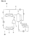
- Patent Literature 1 discloses a heat pump heating system 100 as shown in FIG. 10 .
- This heat pump heating system 100 includes a heat pump 200 having a refrigerant circuit 10 for circulating a refrigerant and a circulation path 16 for circulating water.
- the refrigerant circuit 10 includes a compressor 11, a radiator 12, an expansion valve 13, and an evaporator 14, which are connected in this order by pipes.
- the circulation path 16 has a hot water storage tank 15. Water is taken out of the hot water storage tank 15 and fed to the radiator 12, where hot water is produced. This hot water is stored in the hot water storage tank 15. The hot water stored in the hot water storage tank 15 is fed to, for example, a heater 17 disposed in a room, releases heat there, and then is returned to the hot water storage tank 15.
- Patent Literature 2 discloses, as a heat pump for hot water supply, a heat pump 201 including an internal heat exchanger 18 as shown in Fig. 11 .
- the internal heat exchanger 18 is designed to exchange heat between a high pressure refrigerant flowing out of a radiator 12 and a low pressure refrigerant flowing out of an evaporator 14. With this structure, the temperature of the low pressure refrigerant drawn into a compressor 11 increases, which produces higher temperature hot water.
- Patent Literature 3 discloses a heat pump 202 as shown in Fig. 12A .
- This heat pump 202 is provided with a first radiator 12A and a second radiator 12B as radiators for allowing a refrigerant to release heat.
- a high pressure refrigerant that has released heat in the first radiator 12A releases heat in the internal heat exchanger 18, and then is introduced into the second radiator 12B and further releases heat there.
- water flowing through a flow path 19 is heated in the second radiator 12B and then further heated in the first radiator 12A, as shown in Fig. 12B .
- the temperature of water does not decrease so much in the heater 17 and medium temperature water (for example, at about 40°C to 60°C) is supplied to the radiator 12 of the heat pump 200.
- medium temperature water for example, at about 40°C to 60°C
- the heat exchange efficiency of the radiator 12 decreases, resulting in a decrease in the COP (Coefficient of Performance) of the heat pump 200.
- This problem also occurs when the heat pump 201 shown in Fig. 11 or the heat pump 202 shown in Fig. 12A is used as a heat pump for the heat pump heating system 100 shown in Fig. 10 .
- the present invention has been made in view of the above problem, and it is an object of the present invention to improve the COP of a heat pump in a heat pump heating system even if a medium temperature liquid is fed to the heat pump.
- the present invention provides a heat pump heating system including: a refrigerant circuit including a compressor for changing a low pressure refrigerant to a high pressure refrigerant, a radiator for allowing the high pressure refrigerant to release heat, an expansion member for changing the high pressure refrigerant to the low pressure refrigerant, and an evaporator for allowing the low pressure refrigerant to absorb heat; a circulation path for circulating a liquid through the radiator to produce a heated liquid; a heater for dissipating heat of the heated liquid; an internal heat exchanger, provided in the refrigerant circuit, for transferring heat from the high pressure refrigerant that has released heat in the radiator to the low pressure refrigerant; and a liquid cooling heat exchanger for cooling the liquid flowing through the circulation path by means of the high pressure refrigerant flowing out of the internal heat exchanger, before the liquid flows into the radiator.
- a refrigerant circuit including a compressor for changing a low pressure refrigerant to a high pressure refriger
- a low temperature liquid can be introduced into the radiator even if the temperature of the liquid is medium when it is fed to the heat pump. Therefore, the COP of the heat pump can be improved.
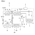
- Fig. 1 shows a heat pump heating system 1A according to the first embodiment of the present invention.
- This heat pump heating system 1A includes a heat pump 20A having a refrigerant circuit 3 for circulating a refrigerant, a circulation path 5 for circulating a liquid, and a controller 6 for controlling the elements totally.
- the circulation path 5 is designed to circulate the liquid through a radiator 22 described later to produce a heated liquid.
- a heater 4 for dissipating the heat of the heated liquid is incorporated in the circulation path 5, so that the liquid is circulated without stopping and the heated liquid thus produced releases heat directly in the heater 4. That is, the circulation path 5 also serves as a heating circuit.
- water is used as the liquid serving as a heat carrier.
- the liquid of the present invention is not necessarily limited to this. Any liquid can be used as long as it can receive heat from the refrigerant circulating through the refrigerant circuit 3 and release heat into the atmosphere in the heater 4.
- the liquid for example, an antifreeze mixture of propylene glycol or the like and water can be used. The following description will be made on the assumption that the liquid is water and the heated liquid is hot water.
- the refrigerant circuit 3 includes a compressor 21 for changing a low pressure refrigerant to a high pressure refrigerant, a radiator 22 for allowing the high pressure refrigerant to release heat, an expansion valve 25A serving as an expansion member for changing the high pressure refrigerant to the low pressure refrigerant, an evaporator 26 for allowing the low pressure refrigerant to absorb heat, and first to fourth pipes 31 to 34 connecting these devices in this order.
- the radiator 22 heat is exchanged between the water passing through the radiator 22 and the refrigerant, and thereby the water is heated.
- the evaporator 26 heat is exchanged between the refrigerant and air blown by a fan 26a, and thereby the refrigerant absorbs heat.
- the refrigerant circuit 3 is filled with carbon dioxide, which reaches a supercritical state on the high pressure side, as the refrigerant.
- An internal heat exchanger 23A is provided in the refrigerant circuit 3 so as to bundle the second pipe 32 and the fourth pipe 34.
- a liquid cooling heat exchanger 24 is provided on the downstream side of the internal heat exchanger 23Ain the second pipe 32.
- the internal heat exchanger 23A is designed to exchange heat between the high pressure refrigerant flowing out of the radiator 22 and the low pressure refrigerant flowing out of the evaporator 26 so as to transfer heat from the high pressure refrigerant that has released heat in the radiator 22 to the low pressure refrigerant.
- the liquid cooling heat exchanger 24 is designed to cool the water flowing through the circulation path 5 by means of the high pressure refrigerant flowing out of the internal heat exchanger 23A, before the water flows into the radiator 22.
- the heater 4 is designed to heat, for example, a room by heat dissipation from hot water.
- a heat dissipating device to be placed in a room may be used.
- a hot water panel to be laid on a floor also may be used.
- the circulation path 5 includes a supply pipe 51 for introducing the water from the heater 4 to the liquid cooling heat exchanger 24, an intermediate pipe 52 for introducing the water from the liquid cooling heat exchanger 24 to the radiator 22, and a recovery pipe 53 for introducing the water in the form of hot water from the radiator 22 to the heater 4.
- the supply pipe 51 is provided with a pump 62.
- the supply pipe 51 is further provided with a temperature sensor 61 for detecting the temperature of the water flowing into the supply pipe 51 from the heater 4.
- the intermediate pipe 52 and the downstream part of the pump 62 in the supply pipe 51 are connected by a bypass pipe 54.
- the supply pipe 51 is provided with a three-way valve 63, and the upstream end of the bypass pipe 54 is joined to this three-way valve 63.
- the downstream end of the bypass pipe 54 is joined to the middle of the intermediate pipe 52.
- the three-way valve 63 is designed to switch between a circulation of the water not through the bypass pipe 54, that is, a circulation of the water passing through both of the liquid cooling heat exchanger 24 and the radiator 22, and a circulation of the water through the bypass pipe 54, that is, a circulation of the water passing only through the radiator 22.
- the three-way valve 63 corresponds to the switching member of the present invention. It should be noted that the switching member of the present invention is not necessarily be the three-way valve 63.
- the switching member may be replaced by an on-off valve provided in the bypass pipe 54 and an on-off valve provided in the downstream of the point of the supply pipe 51 to which the bypass pipe 54 is joined.
- the controller 6 is composed of a microcomputer, a DSP (digital signal processor), or the like, and is connected to the above-mentioned heat pump 20A, and the pump 62, the temperature sensor 61, and the three-way valve 63.
- DSP digital signal processor
- the controller 6 When a user turns on a heating switch (not shown), for example, the controller 6 operates the heat pump 20A and rotates the pump 62. Thereby, the water is heated in the radiator 22 to produce hot water, and this hot water is fed to the heater 4 to perform heating.
- a heating switch not shown
- the controller 6 uses the temperature sensor 61 to monitor the temperature of the water flowing into the supply pipe 51.
- a predetermined temperature for example, 20°C
- the controller 6 controls the three-way valve 63 so that the water is circulated through the bypass pipe 54.
- the controller 6 sets the three-way valve 63 so that the bypass pipe 54 is communicated with the upstream part 51a of the three-way valve 63 in the supply pipe 51.
- the first route passing only through the radiator 22 is selected.
- the refrigerant circulating through the refrigerant circuit 3 operates in the following manner.
- the refrigerant is compressed by the compressor 21 to a high temperature and high pressure state, and then the resulting refrigerant flows into the radiator 22, where it transfers heat to the water flowing through the circulation path 5.
- the refrigerant flows into the internal heat exchanger 23A, where it further transfers heat to the refrigerant flowing out of the evaporator 26.
- the refrigerant passes through the liquid cooling heat exchanger 24 while maintaining its state, and is decompressed by the expansion valve 25A to expand to a low temperature and low pressure state.
- the expanded refrigerant flows into the evaporator 26, where it absorbs heat from air. After flowing out of the evaporator 26, the refrigerant flows into the internal heat exchanger 23A, where it further absorbs heat from the refrigerant flowing out of the radiator 22. After flowing out of the internal heat exchanger 23A, the refrigerant is drawn into the compressor 21 again and compressed there.
- the water circulating through the circulation path 5 (first route) is heated in the radiator 22, and the resulting hot water flows into the heater 4 and releases heat to the atmosphere. After releasing heat in the heater 4, the water flows into the radiator 22 again and is heated to hot water.
- the controller 6 controls the three-way valve 63 so that the water is circulated not through the bypass pipe 54. Specifically, the controller 6 sets the three-way valve 63 so that the upstream part 51a and the downstream part 51b of the three-way valve 63 in the supply pipe 51 are communicated with each other. As a result, the second route passing through both of the liquid cooling heat exchanger 24 and the radiator 22 is selected.
- the water flowing into the liquid cooling heat exchanger 24 has a higher temperature than the refrigerant flowing into the liquid cooling heat exchanger 24.
- the refrigerant circulating in the refrigerant circuit 3 operates in the following manner.
- the refrigerant is compressed by the compressor 21 to a high temperature and high pressure state, and then the resulting refrigerant flows into the radiator 22, where it transfers heat to the water flowing through the circulation path 5.
- the refrigerant flows into the internal heat exchanger 23A, where it further transfers heat to the refrigerant flowing out of the evaporator 26.
- the refrigerant flows into the liquid cooling heat exchanger 24, where it exchanges heat with the water flowing through the circulation path 5.
- the refrigerant is heated almost to the temperature of the water flowing into the liquid cooling heat exchanger 24.
- the refrigerant is decompressed by the expansion valve 25A to expand to a low temperature and low pressure state. Then, it flows into the evaporator 26, where it absorbs heat from air.
- the refrigerant flows into the internal heat exchanger 23A, where it further absorbs heat from the refrigerant flowing out of the radiator 22. After flowing out of the internal heat exchanger 23A, the refrigerant is drawn into the compressor 21 again and compressed there.
- the water circulating through the circulation path 5 (second route) is heated in the radiator 22, and the resulting hot water flows into the heater 4 and releases heat to the atmosphere and becomes medium temperature water.
- the medium temperature water flows into the liquid cooling heat exchanger 24, where it exchanges heat with the refrigerant flowing out of the internal heat exchanger 23A.
- the water is cooled to a low temperature state.
- the low temperature water flows into the radiator 22 again, and is heated to hot water.
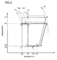
- Fig. 2 shows a Mollier diagram of the heat pump 20A used in the present embodiment, under the medium temperature condition.
- a broken line shows a Mollier diagram of the heat pump 201 without the liquid cooling heat exchanger, as shown in Fig. 11 .
- Points A to F in Fig. 2 represent the states at "x" marks A to F in Fig. 1 .
- the temperature of the refrigerant falls from a high temperature Td' (Point B') resulting from the compressor to a temperature T GC ' (Point C') that is about a temperature Tw1 of the medium temperature water returning from the heater.
- Td' Point B'
- T GC ' Point C'
- Tw1 the medium temperature water returning from the heater.
- the refrigerant After passing through the radiator, the refrigerant further lowers its temperature in the internal heat exchanger and then is decompressed by the expansion valve.
- the enthalpy of the decompressed refrigerant increases from H2'(Point F') to H1'(Point G') as the refrigerant passes through the evaporator, and further increases as it passes through the internal heat exchanger.
- the temperature of the water is Tw2 ( ⁇ Tw1). Accordingly, the temperature of the refrigerant at the outlet of the radiator 22 is T GC (Point C), which is lower than that in the conventional heat pump 201.
- T GC Point C
- T IH Point D
- T EX Point E
- low temperature water can be introduced into the radiator 22 even if the temperature of the water is medium when it is fed to the heat pump 20A. Therefore, the COP of the heat pump 20A can be improved.
- the temperature of the refrigerant at the outlet of the radiator 22 can be reduced to a lower level than that in the conventional heat pump 201. Therefore, the optimum high pressure (high pressure at which the COP of the heat pump is highest) for the temperature of the refrigerant at the outlet of the radiator 22 can be lowered. Accordingly, the differential pressure between the high pressure and the low pressure of the refrigeration cycle can be reduced, and thus the differential pressure force applied to the compression part of the compressor 21 can be lessened. As a result, the leakage loss of the refrigerant and the friction loss are reduced, and thus the efficiency of the compressor 21 can be improved. In addition, since the high pressure of the refrigeration cycle can be lowered, the reliability of the refrigerant circuit 3 also can be improved. Moreover, the pressure resistance strength required for the constituent components can be reduced, and therefore the heating system can be manufactured at lower cost.
- the discharge pressure of the compressor 21 decreases, the temperature of the refrigerant discharged from the compressor 21 can be lowered. Therefore, the deterioration of the components caused by the discharged high temperature refrigerant can be reduced, and the reliability of the elements can be improved. Particularly in the case where the outside temperature drops significantly (to about -5°C to -15°C), the problem of an increase in the temperature of the refrigerant discharged from the compressor can be addressed effectively.
- the enthalpy increment in the evaporator 26 is smaller, the low pressure is higher than that of the conventional heat pump 201. Therefore, the differential pressure between the high pressure and the low pressure of the refrigeration cycle can further be reduced, and thus the differential pressure force applied to the compression part of the compressor 21 can further be lessened. Moreover, since the pressure inside the evaporator 26 increases, the average temperature of the evaporator 26 rises. As a result, when frost forms, the load of defrosting operation can be reduced, and thus the energy consumed by the heat pump 20A can be reduced and the efficiency of the elements can be improved.
- the heat pump 202 disclosed in Patent Literature 3 and shown in Fig. 12A apparently seems to have a configuration similar to that of the heat pump 20A of the present embodiment.
- the first radiator 12A and the second radiator 12B are disposed with the internal heat exchanger 18 being interposed therebetween, and the temperature of the refrigerant only continues to fall and the temperature of the water only continues to rise, as shown in Fig. 12B , which is distinctly different from the action of the heat pump 20A of the present embodiment.
- Patent Literature 3 not only fails to describe the circulation of water but also fails to describe that the water in the form of medium temperature water is returned to the heat pump.
- the bypass pipe 54 and the three-way valve 63 serving as a switching member are provided to select the circulation of the water through either the first route or the second route.
- these members may be omitted so that the water always passes through both of the liquid cooling heat exchanger 24 and the radiator 22.
- the liquid cooling heat exchanger 24 and the radiator 22 used in the present embodiment are both heat exchangers for exchanging heat between water and a refrigerant. Therefore, these devices 24 and 22 can also be manufactured integrally as a single water-refrigerant heat exchanger. In this case, the refrigerant flow path and the water flow path included in the water-refrigerant heat exchanger each can be divided into two. With this structure, a compact heat exchanger can be designed. Therefore, not only the unit (for example, a heat pump unit) in the heating system can be downsized but also the manufacturing cost can be reduced.
- hot water heated in the refrigerant circuit 3 releases heat to the atmosphere in the heater 4.
- the heater 4 also may be used as a heating source for hot water supply or snow melting. Needless to say, the same advantageous effects as above are obtained in these applications.
- carbon dioxide is used as the refrigerant.
- Any refrigerant can be used in the present invention as long as it has the property of decreasing the optimum high pressure as its temperature at the outlet of the radiator 22 decreases. Furthermore, since the difference between the temperature of the refrigerant at the inlet of the radiator 22 and that at the outlet of the radiator 22 increases as the temperature of the refrigerant at the outlet of the radiator 22 decreases, the heat exchange efficiency of the radiator 22 is improved, and as a result, the high pressure drops. Therefore, needless to say, the same advantageous effects as above are obtained even if the refrigerant, like a fluorocarbon refrigerant, does not reach a supercritical state on the high pressure side during the normal operation.
- the internal heat exchanger 23A is used to exchange heat between the high pressure refrigerant flowing out of the radiator 22 and the low pressure refrigerant flowing out of the evaporator 26.
- an internal heat exchanger 23B may be used to exchange heat between the high pressure refrigerant flowing out of the radiator 22 and the low pressure refrigerant before flowing into the evaporator 26, as shown in Fig. 3 .
- the compressor 21 may include a main compressor and an auxiliary compressor connected in parallel thereto.
- Fig. 4 shows a heat pump heating system 1B according to the second embodiment of the present invention.
- the heat pump heating system 1B of the second embodiment has the almost same configuration as the heat pump heating system 1A of the first embodiment. Therefore, the same reference numerals are assigned to the components having the same functions, and no further description of the same configuration and operation is given. The same description is not repeated also in the third to fifth embodiments described below.
- the only difference between the heat pump heating system 1B of the present embodiment and the heat pump heating system 1A of the first embodiment is that in the former system 1B, an expander 25B for recovering power from an expanding refrigerant is used as the expansion member.
- an expander 25B for recovering power from an expanding refrigerant is used as the expansion member.
- Fig. 5 shows a Mollier diagram of a heat pump 20B used in the present embodiment, under the medium temperature condition.
- a broken line shows a Mollier diagram of a heat pump without a liquid cooling heat exchanger.
- the enthalpy of the refrigerant at the inlet of the expander is H3'
- the enthalpy of the refrigerant at the outlet of the expander, where the refrigerant has undergone adiabatic expansion changes (isentropic changes) from D' to F' is H2'.
- the refrigerant after passing through the radiator 22, the refrigerant lowers its temperature in the internal heat exchanger 23A, then is warmed to Point E in the liquid cooling heat exchanger 24, and drawn into the expander 25B.
- the enthalpy of the refrigerant at the inlet of the expander 25B is H3
- the enthalpy of the refrigerant at the outlet of the expander 25B, where the refrigerant has undergone adiabatic expansion changes from D to F is H2.
- the enthalpy change ( ⁇ H) during the adiabatic expansion changes increases as the enthalpy of a refrigerant drawn into an expander increases.
- the energy of power that can be recovered by the expander is proportional to this enthalpy change. Therefore, the energy of power that can be recovered by the expander increases as the enthalpy of the refrigerant drawn into the expander increases. Therefore, the expansion energy that can be recovered by the expander 25A used in the present embodiment is much greater than the expansion energy that can be recovered by the expander in the heat pump without the liquid cooling heat exchanger.
- the COP of the heat pump 20B can be improved dramatically.
- the optimum high pressure can be lowered in the refrigerant circuit 3 of the present embodiment, the difference between the high pressure and the low pressure that acts on the expander 25B can be reduced. Therefore, the leakage loss of the refrigerant and the friction loss are reduced, and thus the efficiency of the expander 25B can be improved. As a result, more expansion energy can be obtained.
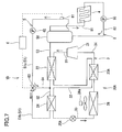
- Fig. 6 shows a heat pump heating system 1C according to the third embodiment of the present invention.
- the heat pump heating system 1C of the present embodiment is different from the heat pump heating system 1A of the first embodiment in that an ejector 25C is used as the expansion member.
- the ejector 25C is connected to the radiator 22 by the second pipe 32 and to the evaporator 26 by the third pipe 33.
- a gas-liquid separator 27 is provided in the middle of the third pipe 33.
- the evaporator 26 is connected to the ejector 25C by a divided fourth pipe 34A, and the gas phase portion of the gas-liquid separator 27 is connected to the compressor 21 by a divided fourth pipe 34B.
- the internal heat exchanger 23A is provided so as to bundle the second pipe 32 and the divided fourth pipe 34B.
- the refrigerant that has passed through the internal heat exchanger 23A and the liquid cooling heat exchanger 24 flows into the ejector 25C and expands there.
- the refrigerant flowing out of the ejector 25C is separated into a gas refrigerant and a liquid refrigerant.
- the liquid refrigerant is fed to the evaporator 26 and evaporated there, and then flows into the ejector 25C again.
- the gas refrigerant separated by the gas-liquid separator 27 flows into the internal heat exchanger 23A and is heated there by the refrigerant that has released heat in the radiator 22.
- the other operations and actions of the refrigerant and water are the same as those in the first embodiment.
- the expansion energy can be increased, as in the second embodiment. Therefore, the flow velocity of the refrigerant in the ejector 25C can be increased, and thus the pressure of the refrigerant drawn into the compressor 21 can further be increased. Accordingly, the compression power required for the compressor 21 can be reduced, and thus the COP of the heat pump 20C can be improved.
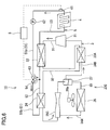
- Fig. 7 shows a heat pump heating system 1D according to the fourth embodiment of the present invention.
- the heat pump heating system 1D of the present embodiment is different from the heat pump heating system 1A of the first embodiment in that the circulation path 5 is provided with a hot water storage tank 50 instead of the heater 4.
- the hot water storage tank 50 is a vertically extending cylindrical closed casing and is filled with water.
- the lower portion of the hot water storage tank 50 is connected to the liquid cooling heat exchanger 24 by the supply pipe 51, and the upper portion thereof is connected to the radiator 22 by the recovery pipe 53.
- the pump 62 When the pump 62 is rotated, the water is introduced from the lower portion of the hot water storage tank 50 to the liquid cooling heat exchanger 24 through the supply pipe 31, and the water in the form of hot water is introduced from the radiator 22 to the upper portion of the hot water storage tank 50 through the recovery pipe 53.
- the hot water is stored in the hot water storage tank 50 from the top.
- the temperature of the water flowing into the supply pipe 51 from the hot water storage tank 51 is detected by the temperature sensor 61 provided in the supply pipe 51.
- the heater 4 is connected to the upper portion of the hot water storage tank 50 by a feed pipe 81, and to the lower portion of the hot water storage tank 50 by a return pipe 82.
- a heating pump 65 is provided in the return pipe 82, but the heating pump 65 may be provided in the feed pipe 81.
- the heating pump 65 is connected to the controller 6. When the heating pump 65 is rotated, the hot water stored in the hot water storage tank 50 is fed to the heater 4 through the feed pipe 81, and the hot water that has released heat in the heater 4 is returned to the hot water storage tank 50. That is, the hot water storage tank 50, the feed pipe 81, the heater 4, and the return pipe 82 constitute a heating circuit 8.
- the controller 6 determines, with a sensor (not shown) provided in the hot water storage tank 50, that the amount of hot water left in the hot water storage tank 50 is insufficient, it operates the heat pump 20A and rotates the pump 62. Thereby, the water is heated in the radiator 22 to produce hot water, and this hot water is fed to the hot water storage tank 50 for the storage of hot water.
- the controller 6 uses the temperature sensor 61 to monitor the temperature of the water flowing into the supply pipe 51.
- the controller 6 controls the three-way valve 63 so that the water is circulated through the bypass pipe 54.
- the controller 6 sets the three-way valve 63 so that the bypass pipe 54 is communicated with the upstream part 51a of the three-way valve 63 in the supply pipe 51.
- the first route passing only through the radiator 22 is selected.
- the refrigerant circulating through the refrigerant circuit 3 operates in the same manner as in the first embodiment.
- the water circulating through the circulation path 5 (first route) is heated in the radiator 22, and the resulting hot water is stored in the hot water storage tank 50.
- the water is taken from the lower portion of the hot water storage tank 50, and then flows into the radiator 22 again, where it is heated to hot water.
- the controller 6 controls the three-way valve 63 so that the water is circulated not through the bypass pipe 54. Specifically, the controller 6 sets the three-way valve 63 so that the upstream part 51a and the downstream part 51b of the three-way valve 63 in the supply pipe 51 are communicated with each other. As a result, the second route passing through both of the liquid cooling heat exchanger 24 and the radiator 22 is selected.
- the water flowing into the liquid cooling heat exchanger 24 has a higher temperature than the refrigerant flowing into the liquid cooling heat exchanger 24.
- the refrigerant circulating through the refrigerant circuit 3 operates in the same manner as in the first embodiment.
- the water circulating through the circulation path 5 (second route) is heated in the radiator 22, and the resulting hot water is stored in the hot water storage tank 50.
- Medium temperature water that has not released sufficient heat in the heater 4 is stored in the lower portion of the hot water storage tank 50.
- the medium temperature water is taken from the lower portion of the hot water storage tank 50, and flows into the liquid cooling heat exchanger 24, where it exchanges heat with the refrigerant flowing out of the internal heat exchanger 23A. As a result, the water is cooled to a low temperature state.
- the low temperature water flows into the radiator 22 again and is heated to hot water.
- the controller 6 rotates the heating pump 65. Thereby, the hot water stored in the hot water storage tank 50 is fed to the heater 4 for performing heating.
- the heated hot water can be stored once in the hot water storage tank 50. Therefore, for example, in the case where heating is interrupted and then resumed, the hot water stored in the hot water storage tank 50 can be fed to the heater 4 before the water that has cooled down during the interruption of the heating operation is reheated in the heat pump 20A, and thereby the heating operation can be resumed quickly.
- high temperature hot water can be produced at low electricity prices during night hours and this hot water can be stored in the hot water storage tank 50. Therefore, the running cost of the heating operation can be reduced.
- a water inlet pipe 91 for supplying tap water to the hot water storage tank 50 may be provided in the hot water storage tank 50.
- the temperature of hot water flowing into the heater 4 can be controlled freely by mixing tap water and hot water flowing into the heater 4 or exchanging heat between them.
- tap water can be used to control the temperature of water flowing into the heater 4
- the optimum temperature water is allowed to flow into the heater 4 even if the temperature of hot water stored in the hot water storage tank 50 is higher than that of hot water to be used in the heater 4.
- the amount of heat stored in the hot water storage tank 50 can be increased. Therefore, even if the operation of the heat pump 20Ais stopped for a long time, heating operation can be continued in the heating circuit 8.
- a mixing valve 91 may be provided in the feed pipe 81 to connect the water inlet pipe 91 to this mixing valve.
- a hot water outlet pipe 92 (see Fig. 8 ) for withdrawing hot water from the hot water storage tank 50 also may be provided in the hot water storage tank 50. With this structure, hot water also can be supplied during heating operation.
- the heat pump 20B shown in Fig. 4 using the expander 25B as the expansion member or the heat pump 20C shown in Fig. 6 using the ejector 25C as the expansion member can be used in the embodiment described above.
- Fig. 8 shows a heat pump heating system 1E according to the fifth embodiment of the present invention.
- the heat pump heating system 1E of the present embodiment is different from the heat pump heating system 1D of the fourth embodiment in that an in-tank heat exchanger 83 is disposed in the hot water storage tank 50.
- the water inlet pipe 91 is connected to the lower portion of the hot water storage tank 50, and the hot water outlet pipe 92 is connected to the upper portion of the hot water storage tank 50.
- the in-tank heat exchanger 83 is designed to heat a heat carrier that is a second liquid by means of the hot water stored in the hot water storage tank 50.
- the in-tank heat exchanger 83 is connected to the heater 4 by the feed pipe 81 and the return pipe 82.
- the heat carrier for example, an antifreeze liquid can be used, but water preferably is used because it is available at low cost and in large quantities.
- the controller 6 performs control in the same manner as in the fourth embodiment, the description thereof is not repeated here. It should be noted, however, that during the heating operation, the heat carrier that has exchanged heat with the hot water stored in the hot water storage tank 50 releases heat in the heater 4, that is, the heat of the hot water is dissipated through the heat carrier in the heater 4, and thereby heating is performed.
- Fig. 9 shows a heat pump heating system 1F according to the sixth embodiment of the present invention.
- the heat pump heating system 1F of the present embodiment includes a structure for hot water supply in addition to the heat pump heating system 1D of the fourth embodiment.
- a hot water supply heat exchanger 93 is disposed in the hot water storage tank 50, and the water inlet pipe 91 and the hot water outlet pipe 92 are connected to this hot water supply heat exchanger 93. That is, in the present embodiment, tap water flowing from the water inlet pipe 91 to the hot water outlet pipe 92 is heated by means of hot water in the hot water storage tank 50 so as to produce hot water.
- the heat pump heating system of the present invention is useful as a means for improving the COP of a heat pump through the use of medium temperature water produced in a heater.
Landscapes
- Engineering & Computer Science (AREA)
- Physics & Mathematics (AREA)
- Mechanical Engineering (AREA)
- Thermal Sciences (AREA)
- General Engineering & Computer Science (AREA)
- Chemical & Material Sciences (AREA)
- Combustion & Propulsion (AREA)
- Water Supply & Treatment (AREA)
- Computer Hardware Design (AREA)
- Chemical Kinetics & Catalysis (AREA)
- Steam Or Hot-Water Central Heating Systems (AREA)
- Heat-Pump Type And Storage Water Heaters (AREA)
Applications Claiming Priority (2)
| Application Number | Priority Date | Filing Date | Title |
|---|---|---|---|
| JP2009096623 | 2009-04-13 | ||
| PCT/JP2010/002542 WO2010119642A1 (fr) | 2009-04-13 | 2010-04-07 | Dispositif de chauffage de type pompe à chaleur |
Publications (4)
| Publication Number | Publication Date |
|---|---|
| EP2420746A1 true EP2420746A1 (fr) | 2012-02-22 |
| EP2420746A4 EP2420746A4 (fr) | 2014-03-12 |
| EP2420746B1 EP2420746B1 (fr) | 2016-01-13 |
| EP2420746B8 EP2420746B8 (fr) | 2016-04-06 |
Family
ID=42982317
Family Applications (1)
| Application Number | Title | Priority Date | Filing Date |
|---|---|---|---|
| EP10764229.0A Not-in-force EP2420746B8 (fr) | 2009-04-13 | 2010-04-07 | Dispositif de chauffage de type pompe à chaleur |
Country Status (5)
| Country | Link |
|---|---|
| US (2) | US20120000236A1 (fr) |
| EP (1) | EP2420746B8 (fr) |
| JP (1) | JP5470374B2 (fr) |
| CN (1) | CN102369397B (fr) |
| WO (1) | WO2010119642A1 (fr) |
Cited By (1)
| Publication number | Priority date | Publication date | Assignee | Title |
|---|---|---|---|---|
| EP2918921A1 (fr) * | 2014-03-12 | 2015-09-16 | Panasonic Intellectual Property Management Co., Ltd. | Générateur d'eau chaude |
Families Citing this family (25)
| Publication number | Priority date | Publication date | Assignee | Title |
|---|---|---|---|---|
| JP5729910B2 (ja) * | 2010-03-05 | 2015-06-03 | 三菱重工業株式会社 | 温水ヒートポンプおよびその制御方法 |
| JP5960955B2 (ja) * | 2010-12-03 | 2016-08-02 | 現代自動車株式会社Hyundai Motor Company | 車両用コンデンサ |
| ITTO20111133A1 (it) * | 2011-12-12 | 2013-06-13 | Innovation Factory Scarl | Unita' a pompa di calore ad alte prestazioni |
| JP5494770B2 (ja) * | 2012-09-25 | 2014-05-21 | 三菱電機株式会社 | ヒートポンプ給湯機 |
| CN103197624A (zh) * | 2013-03-05 | 2013-07-10 | 天津城市建设学院 | 基于dsp的集中供热系统控制器 |
| FR3003936A3 (fr) * | 2013-03-27 | 2014-10-03 | Nextherm | Installation de pompe a chaleur fonctionnant a partir d'une source froide |
| DE102013012926A1 (de) * | 2013-08-02 | 2015-02-05 | Man Truck & Bus Ag | Wärmepumpe, insbesondere zur Heizung eines Fahrzeuginnenraums, sowie Verfahren zum Betreiben einer Wärmepumpe |
| JP5999273B2 (ja) * | 2013-10-17 | 2016-09-28 | 三菱電機株式会社 | 冷凍サイクル装置 |
| EP3059519B1 (fr) * | 2013-10-17 | 2021-03-03 | Mitsubishi Electric Corporation | Dispositif à cycle de réfrigération |
| JP2016003828A (ja) * | 2014-06-18 | 2016-01-12 | 株式会社デンソー | 冷凍サイクル装置 |
| JPWO2016098263A1 (ja) * | 2014-12-19 | 2017-10-05 | サンデンホールディングス株式会社 | 熱交換器及びこれを用いたヒートポンプ式温水生成装置 |
| WO2016147389A1 (fr) * | 2015-03-19 | 2016-09-22 | 三菱電機株式会社 | Système de pompe à chaleur |
| CN106287901A (zh) * | 2015-06-05 | 2017-01-04 | 青岛海尔新能源电器有限公司 | 二氧化碳热泵加热装置 |
| US11255580B2 (en) * | 2015-08-20 | 2022-02-22 | Lennox Industries Inc. | Carbon dioxide cooling system with subcooling |
| CN106568232A (zh) * | 2015-10-13 | 2017-04-19 | 凯洛格·布朗及鲁特有限公司 | 在c2分离器底部以免除丙烯制冷装置的热泵 |
| EP3296666A1 (fr) * | 2016-09-14 | 2018-03-21 | Siemens Aktiengesellschaft | Préparation d'amidon pour l'hydrophobisation de papier |
| KR101946491B1 (ko) * | 2016-12-23 | 2019-02-11 | 한국에너지기술연구원 | 리큐퍼레이터를 이용한 스팀 생산 히트펌프 시스템 |
| EP3376121A1 (fr) * | 2017-03-17 | 2018-09-19 | Sharp Kabushiki Kaisha | Dispositif d'échange de chaleur et procédé de fonctionnement d'un dispositif d'échange de chaleur |
| CN107024017A (zh) * | 2017-03-23 | 2017-08-08 | 北京国科天创建筑设计院有限责任公司 | 一种高进水温度的复迭式二氧化碳热泵系统 |
| JP2018169108A (ja) * | 2017-03-30 | 2018-11-01 | 三菱重工サーマルシステムズ株式会社 | 加熱装置、及び、加熱方法 |
| JP7113210B2 (ja) * | 2018-12-17 | 2022-08-05 | パナソニックIpマネジメント株式会社 | ヒートポンプシステム |
| EP3756916B1 (fr) * | 2019-06-24 | 2023-09-27 | Konvekta Aktiengesellschaft | Installation de chauffage et / ou de climatisation pourvue d'échangeurs de chaleur internes |
| DE102020115269A1 (de) | 2020-06-09 | 2021-12-09 | Stiebel Eltron Gmbh & Co. Kg | Verfahren zum Betrieb einer Kompressionskälteanlage und zugehörige Kompressionskälteanlage |
| FR3120684B1 (fr) * | 2021-03-15 | 2023-02-24 | Valeo Systemes Thermiques | Système de conditionnement thermique |
| DE102022121699A1 (de) * | 2022-08-26 | 2024-02-29 | Konvekta Aktiengesellschaft | Wärmepumpenanlage mit mehrstufiger Wärmeübertragung und Verfahren dazu |
Citations (3)
| Publication number | Priority date | Publication date | Assignee | Title |
|---|---|---|---|---|
| JP2002162123A (ja) * | 2000-11-21 | 2002-06-07 | Sekisui Chem Co Ltd | ヒートポンプ |
| JP2004198045A (ja) * | 2002-12-19 | 2004-07-15 | Denso Corp | 蒸気圧縮式冷凍機 |
| DE202005013499U1 (de) * | 2005-08-26 | 2005-10-27 | Wenzel, Bernhard | Kältemittelkreislauf für eine Wärmepumpe |
Family Cites Families (13)
| Publication number | Priority date | Publication date | Assignee | Title |
|---|---|---|---|---|
| SE440551B (sv) * | 1981-03-20 | 1985-08-05 | Thermia Verken Ab | Vermepump for uppvermning och tappvarmvattenberedning |
| KR100567488B1 (ko) * | 2002-02-12 | 2006-04-03 | 마츠시타 덴끼 산교 가부시키가이샤 | 히트 펌프 급탕 장치 |
| JP2004177067A (ja) * | 2002-11-29 | 2004-06-24 | Hitachi Home & Life Solutions Inc | ヒートポンプ式空気調和機 |
| CN1529107A (zh) * | 2003-10-21 | 2004-09-15 | 大连冰山集团有限公司 | 并联二级水环复合热泵驱动采暖空调热水系统 |
| JP4101198B2 (ja) * | 2004-03-24 | 2008-06-18 | 三洋電機株式会社 | ヒートポンプ式給湯暖房装置 |
| ES2401798T3 (es) * | 2004-11-19 | 2013-04-24 | Mayekawa Mfg. Co., Ltd. | Sistema de suministro de agua caliente y acondicionamiento de aire que utiliza una bomba de calor de CO2 |
| JP2006300487A (ja) * | 2005-04-25 | 2006-11-02 | Matsushita Electric Ind Co Ltd | ヒートポンプ給湯装置 |
| JP4736727B2 (ja) * | 2005-11-11 | 2011-07-27 | ダイキン工業株式会社 | ヒートポンプ給湯装置 |
| JP4743039B2 (ja) * | 2006-08-07 | 2011-08-10 | ダイキン工業株式会社 | 建物において温水を循環させて暖房を行う温水循環暖房システム |
| US8549868B2 (en) * | 2007-06-22 | 2013-10-08 | Panasonic Corporation | Refrigeration cycle apparatus |
| JP5018496B2 (ja) * | 2008-01-16 | 2012-09-05 | ダイキン工業株式会社 | 冷凍装置 |
| JP5042058B2 (ja) * | 2008-02-07 | 2012-10-03 | 三菱電機株式会社 | ヒートポンプ式給湯用室外機及びヒートポンプ式給湯装置 |
| US8657207B2 (en) * | 2008-08-26 | 2014-02-25 | Lg Electronics Inc. | Hot water circulation system associated with heat pump and method for controlling the same |
-
2010
- 2010-04-07 WO PCT/JP2010/002542 patent/WO2010119642A1/fr active Application Filing
- 2010-04-07 CN CN201080014403.1A patent/CN102369397B/zh not_active Expired - Fee Related
- 2010-04-07 JP JP2011509197A patent/JP5470374B2/ja not_active Expired - Fee Related
- 2010-04-07 EP EP10764229.0A patent/EP2420746B8/fr not_active Not-in-force
- 2010-04-07 US US13/257,205 patent/US20120000236A1/en not_active Abandoned
-
2017
- 2017-03-10 US US15/456,073 patent/US20170184314A1/en not_active Abandoned
Patent Citations (3)
| Publication number | Priority date | Publication date | Assignee | Title |
|---|---|---|---|---|
| JP2002162123A (ja) * | 2000-11-21 | 2002-06-07 | Sekisui Chem Co Ltd | ヒートポンプ |
| JP2004198045A (ja) * | 2002-12-19 | 2004-07-15 | Denso Corp | 蒸気圧縮式冷凍機 |
| DE202005013499U1 (de) * | 2005-08-26 | 2005-10-27 | Wenzel, Bernhard | Kältemittelkreislauf für eine Wärmepumpe |
Non-Patent Citations (2)
| Title |
|---|
| SARKAR J ET AL: "OPTIMIZATION OF A TRANSCRITICAL CO2 HEAT PUMP CYCLE FOR SIMULTANEOUS COOLING AND HEATING APPLICATIONS", INTERNATIONAL JOURNAL OF REFRIGERATION, ELSEVIER, PARIS, FR, vol. 27, no. 8, 9 March 2004 (2004-03-09), pages 830-838, XP008040143, ISSN: 0140-7007, DOI: 10.1016/J.IJREFRIG.2004.03.006 * |
| See also references of WO2010119642A1 * |
Cited By (1)
| Publication number | Priority date | Publication date | Assignee | Title |
|---|---|---|---|---|
| EP2918921A1 (fr) * | 2014-03-12 | 2015-09-16 | Panasonic Intellectual Property Management Co., Ltd. | Générateur d'eau chaude |
Also Published As
| Publication number | Publication date |
|---|---|
| JP5470374B2 (ja) | 2014-04-16 |
| EP2420746B8 (fr) | 2016-04-06 |
| EP2420746B1 (fr) | 2016-01-13 |
| EP2420746A4 (fr) | 2014-03-12 |
| CN102369397A (zh) | 2012-03-07 |
| JPWO2010119642A1 (ja) | 2012-10-22 |
| WO2010119642A1 (fr) | 2010-10-21 |
| US20120000236A1 (en) | 2012-01-05 |
| CN102369397B (zh) | 2014-03-26 |
| US20170184314A1 (en) | 2017-06-29 |
Similar Documents
| Publication | Publication Date | Title |
|---|---|---|
| EP2420746B1 (fr) | Dispositif de chauffage de type pompe à chaleur | |
| JP5327308B2 (ja) | 給湯空調システム | |
| EP2597381B1 (fr) | Appareil d'alimentation d'eau chaude/froide | |
| JP4784088B2 (ja) | 熱交換システム | |
| WO2012032680A1 (fr) | Appareil à cycle de réfrigération | |
| CN118031483A (zh) | 蒸汽压缩制冷系统中的反循环除霜基于相变材料的增强 | |
| JP5419437B2 (ja) | 空調複合給湯装置 | |
| JP5842310B2 (ja) | 冷凍装置、および負荷冷却器のデフロスト方法 | |
| CN102575860A (zh) | 空气调节装置 | |
| JP2014169854A (ja) | 冷凍サイクル装置およびそれを備えた温水生成装置 | |
| JP2004218944A (ja) | ヒートポンプ式冷暖房給湯装置 | |
| JP2007163071A (ja) | ヒートポンプ式冷暖房装置 | |
| JP2011085284A (ja) | ヒートポンプ式暖房装置 | |
| JP2013083439A (ja) | 給湯空調システム | |
| JP2013083439A5 (fr) | ||
| US20070240430A1 (en) | Cooling Device | |
| JP2008249248A (ja) | ヒートポンプ式給湯システム | |
| JP6689801B2 (ja) | 太陽熱空調システム | |
| JP4033788B2 (ja) | ヒートポンプ装置 | |
| JP2020003173A (ja) | 機器温調装置 | |
| JP5150300B2 (ja) | ヒートポンプ式給湯装置 | |
| TW201319492A (zh) | 具熱回收功能之冷媒循環系統 | |
| JP5166840B2 (ja) | ヒートポンプシステム | |
| JP5150225B2 (ja) | ヒートポンプシステム | |
| JP2014031930A (ja) | 冷凍サイクル装置 |
Legal Events
| Date | Code | Title | Description |
|---|---|---|---|
| PUAI | Public reference made under article 153(3) epc to a published international application that has entered the european phase |
Free format text: ORIGINAL CODE: 0009012 |
|
| 17P | Request for examination filed |
Effective date: 20111114 |
|
| AK | Designated contracting states |
Kind code of ref document: A1 Designated state(s): AT BE BG CH CY CZ DE DK EE ES FI FR GB GR HR HU IE IS IT LI LT LU LV MC MK MT NL NO PL PT RO SE SI SK SM TR |
|
| DAX | Request for extension of the european patent (deleted) | ||
| A4 | Supplementary search report drawn up and despatched |
Effective date: 20140210 |
|
| RIC1 | Information provided on ipc code assigned before grant |
Ipc: F24D 3/10 20060101ALI20140204BHEP Ipc: F24D 3/18 20060101AFI20140204BHEP Ipc: F24D 19/10 20060101ALI20140204BHEP Ipc: F25B 30/02 20060101ALI20140204BHEP Ipc: F24D 3/08 20060101ALI20140204BHEP Ipc: F24D 17/02 20060101ALI20140204BHEP |
|
| 17Q | First examination report despatched |
Effective date: 20150211 |
|
| RAP1 | Party data changed (applicant data changed or rights of an application transferred) |
Owner name: PANASONIC INTELLECTUAL PROPERTY MANAGEMENT CO., LT |
|
| GRAP | Despatch of communication of intention to grant a patent |
Free format text: ORIGINAL CODE: EPIDOSNIGR1 |
|
| INTG | Intention to grant announced |
Effective date: 20150715 |
|
| GRAS | Grant fee paid |
Free format text: ORIGINAL CODE: EPIDOSNIGR3 |
|
| GRAA | (expected) grant |
Free format text: ORIGINAL CODE: 0009210 |
|
| AK | Designated contracting states |
Kind code of ref document: B1 Designated state(s): AT BE BG CH CY CZ DE DK EE ES FI FR GB GR HR HU IE IS IT LI LT LU LV MC MK MT NL NO PL PT RO SE SI SK SM TR |
|
| REG | Reference to a national code |
Ref country code: GB Ref legal event code: FG4D |
|
| REG | Reference to a national code |
Ref country code: CH Ref legal event code: EP |
|
| REG | Reference to a national code |
Ref country code: IE Ref legal event code: FG4D |
|
| REG | Reference to a national code |
Ref country code: AT Ref legal event code: REF Ref document number: 770785 Country of ref document: AT Kind code of ref document: T Effective date: 20160215 |
|
| REG | Reference to a national code |
Ref country code: DE Ref legal event code: R096 Ref document number: 602010030189 Country of ref document: DE |
|
| GRAT | Correction requested after decision to grant or after decision to maintain patent in amended form |
Free format text: ORIGINAL CODE: EPIDOSNCDEC |
|
| REG | Reference to a national code |
Ref country code: LT Ref legal event code: MG4D |
|
| REG | Reference to a national code |
Ref country code: NL Ref legal event code: MP Effective date: 20160113 |
|
| REG | Reference to a national code |
Ref country code: AT Ref legal event code: MK05 Ref document number: 770785 Country of ref document: AT Kind code of ref document: T Effective date: 20160113 |
|
| PG25 | Lapsed in a contracting state [announced via postgrant information from national office to epo] |
Ref country code: NL Free format text: LAPSE BECAUSE OF FAILURE TO SUBMIT A TRANSLATION OF THE DESCRIPTION OR TO PAY THE FEE WITHIN THE PRESCRIBED TIME-LIMIT Effective date: 20160113 |
|
| PG25 | Lapsed in a contracting state [announced via postgrant information from national office to epo] |
Ref country code: HR Free format text: LAPSE BECAUSE OF FAILURE TO SUBMIT A TRANSLATION OF THE DESCRIPTION OR TO PAY THE FEE WITHIN THE PRESCRIBED TIME-LIMIT Effective date: 20160113 Ref country code: IT Free format text: LAPSE BECAUSE OF FAILURE TO SUBMIT A TRANSLATION OF THE DESCRIPTION OR TO PAY THE FEE WITHIN THE PRESCRIBED TIME-LIMIT Effective date: 20160113 Ref country code: GR Free format text: LAPSE BECAUSE OF FAILURE TO SUBMIT A TRANSLATION OF THE DESCRIPTION OR TO PAY THE FEE WITHIN THE PRESCRIBED TIME-LIMIT Effective date: 20160414 Ref country code: ES Free format text: LAPSE BECAUSE OF FAILURE TO SUBMIT A TRANSLATION OF THE DESCRIPTION OR TO PAY THE FEE WITHIN THE PRESCRIBED TIME-LIMIT Effective date: 20160113 Ref country code: FI Free format text: LAPSE BECAUSE OF FAILURE TO SUBMIT A TRANSLATION OF THE DESCRIPTION OR TO PAY THE FEE WITHIN THE PRESCRIBED TIME-LIMIT Effective date: 20160113 Ref country code: NO Free format text: LAPSE BECAUSE OF FAILURE TO SUBMIT A TRANSLATION OF THE DESCRIPTION OR TO PAY THE FEE WITHIN THE PRESCRIBED TIME-LIMIT Effective date: 20160413 |
|
| PG25 | Lapsed in a contracting state [announced via postgrant information from national office to epo] |
Ref country code: PL Free format text: LAPSE BECAUSE OF FAILURE TO SUBMIT A TRANSLATION OF THE DESCRIPTION OR TO PAY THE FEE WITHIN THE PRESCRIBED TIME-LIMIT Effective date: 20160113 Ref country code: IS Free format text: LAPSE BECAUSE OF FAILURE TO SUBMIT A TRANSLATION OF THE DESCRIPTION OR TO PAY THE FEE WITHIN THE PRESCRIBED TIME-LIMIT Effective date: 20160513 Ref country code: SE Free format text: LAPSE BECAUSE OF FAILURE TO SUBMIT A TRANSLATION OF THE DESCRIPTION OR TO PAY THE FEE WITHIN THE PRESCRIBED TIME-LIMIT Effective date: 20160113 Ref country code: BE Free format text: LAPSE BECAUSE OF NON-PAYMENT OF DUE FEES Effective date: 20160430 Ref country code: AT Free format text: LAPSE BECAUSE OF FAILURE TO SUBMIT A TRANSLATION OF THE DESCRIPTION OR TO PAY THE FEE WITHIN THE PRESCRIBED TIME-LIMIT Effective date: 20160113 Ref country code: PT Free format text: LAPSE BECAUSE OF FAILURE TO SUBMIT A TRANSLATION OF THE DESCRIPTION OR TO PAY THE FEE WITHIN THE PRESCRIBED TIME-LIMIT Effective date: 20160513 Ref country code: LT Free format text: LAPSE BECAUSE OF FAILURE TO SUBMIT A TRANSLATION OF THE DESCRIPTION OR TO PAY THE FEE WITHIN THE PRESCRIBED TIME-LIMIT Effective date: 20160113 Ref country code: LV Free format text: LAPSE BECAUSE OF FAILURE TO SUBMIT A TRANSLATION OF THE DESCRIPTION OR TO PAY THE FEE WITHIN THE PRESCRIBED TIME-LIMIT Effective date: 20160113 |
|
| REG | Reference to a national code |
Ref country code: DE Ref legal event code: R097 Ref document number: 602010030189 Country of ref document: DE |
|
| PG25 | Lapsed in a contracting state [announced via postgrant information from national office to epo] |
Ref country code: EE Free format text: LAPSE BECAUSE OF FAILURE TO SUBMIT A TRANSLATION OF THE DESCRIPTION OR TO PAY THE FEE WITHIN THE PRESCRIBED TIME-LIMIT Effective date: 20160113 Ref country code: DK Free format text: LAPSE BECAUSE OF FAILURE TO SUBMIT A TRANSLATION OF THE DESCRIPTION OR TO PAY THE FEE WITHIN THE PRESCRIBED TIME-LIMIT Effective date: 20160113 |
|
| PLBE | No opposition filed within time limit |
Free format text: ORIGINAL CODE: 0009261 |
|
| STAA | Information on the status of an ep patent application or granted ep patent |
Free format text: STATUS: NO OPPOSITION FILED WITHIN TIME LIMIT |
|
| PG25 | Lapsed in a contracting state [announced via postgrant information from national office to epo] |
Ref country code: CZ Free format text: LAPSE BECAUSE OF FAILURE TO SUBMIT A TRANSLATION OF THE DESCRIPTION OR TO PAY THE FEE WITHIN THE PRESCRIBED TIME-LIMIT Effective date: 20160113 Ref country code: SK Free format text: LAPSE BECAUSE OF FAILURE TO SUBMIT A TRANSLATION OF THE DESCRIPTION OR TO PAY THE FEE WITHIN THE PRESCRIBED TIME-LIMIT Effective date: 20160113 Ref country code: RO Free format text: LAPSE BECAUSE OF FAILURE TO SUBMIT A TRANSLATION OF THE DESCRIPTION OR TO PAY THE FEE WITHIN THE PRESCRIBED TIME-LIMIT Effective date: 20160113 Ref country code: SM Free format text: LAPSE BECAUSE OF FAILURE TO SUBMIT A TRANSLATION OF THE DESCRIPTION OR TO PAY THE FEE WITHIN THE PRESCRIBED TIME-LIMIT Effective date: 20160113 |
|
| REG | Reference to a national code |
Ref country code: CH Ref legal event code: PL |
|
| 26N | No opposition filed |
Effective date: 20161014 |
|
| GBPC | Gb: european patent ceased through non-payment of renewal fee |
Effective date: 20160413 |
|
| PG25 | Lapsed in a contracting state [announced via postgrant information from national office to epo] |
Ref country code: BE Free format text: LAPSE BECAUSE OF FAILURE TO SUBMIT A TRANSLATION OF THE DESCRIPTION OR TO PAY THE FEE WITHIN THE PRESCRIBED TIME-LIMIT Effective date: 20160113 Ref country code: LU Free format text: LAPSE BECAUSE OF FAILURE TO SUBMIT A TRANSLATION OF THE DESCRIPTION OR TO PAY THE FEE WITHIN THE PRESCRIBED TIME-LIMIT Effective date: 20160407 |
|
| REG | Reference to a national code |
Ref country code: IE Ref legal event code: MM4A |
|
| REG | Reference to a national code |
Ref country code: FR Ref legal event code: ST Effective date: 20161230 |
|
| PG25 | Lapsed in a contracting state [announced via postgrant information from national office to epo] |
Ref country code: FR Free format text: LAPSE BECAUSE OF NON-PAYMENT OF DUE FEES Effective date: 20160502 Ref country code: CH Free format text: LAPSE BECAUSE OF NON-PAYMENT OF DUE FEES Effective date: 20160430 Ref country code: LI Free format text: LAPSE BECAUSE OF NON-PAYMENT OF DUE FEES Effective date: 20160430 Ref country code: GB Free format text: LAPSE BECAUSE OF NON-PAYMENT OF DUE FEES Effective date: 20160413 |
|
| PG25 | Lapsed in a contracting state [announced via postgrant information from national office to epo] |
Ref country code: SI Free format text: LAPSE BECAUSE OF FAILURE TO SUBMIT A TRANSLATION OF THE DESCRIPTION OR TO PAY THE FEE WITHIN THE PRESCRIBED TIME-LIMIT Effective date: 20160113 Ref country code: BG Free format text: LAPSE BECAUSE OF FAILURE TO SUBMIT A TRANSLATION OF THE DESCRIPTION OR TO PAY THE FEE WITHIN THE PRESCRIBED TIME-LIMIT Effective date: 20160413 |
|
| PG25 | Lapsed in a contracting state [announced via postgrant information from national office to epo] |
Ref country code: IE Free format text: LAPSE BECAUSE OF NON-PAYMENT OF DUE FEES Effective date: 20160407 |
|
| PG25 | Lapsed in a contracting state [announced via postgrant information from national office to epo] |
Ref country code: HU Free format text: LAPSE BECAUSE OF FAILURE TO SUBMIT A TRANSLATION OF THE DESCRIPTION OR TO PAY THE FEE WITHIN THE PRESCRIBED TIME-LIMIT; INVALID AB INITIO Effective date: 20100407 Ref country code: CY Free format text: LAPSE BECAUSE OF FAILURE TO SUBMIT A TRANSLATION OF THE DESCRIPTION OR TO PAY THE FEE WITHIN THE PRESCRIBED TIME-LIMIT Effective date: 20160113 |
|
| PG25 | Lapsed in a contracting state [announced via postgrant information from national office to epo] |
Ref country code: MC Free format text: LAPSE BECAUSE OF FAILURE TO SUBMIT A TRANSLATION OF THE DESCRIPTION OR TO PAY THE FEE WITHIN THE PRESCRIBED TIME-LIMIT Effective date: 20160113 Ref country code: TR Free format text: LAPSE BECAUSE OF FAILURE TO SUBMIT A TRANSLATION OF THE DESCRIPTION OR TO PAY THE FEE WITHIN THE PRESCRIBED TIME-LIMIT Effective date: 20160113 Ref country code: MT Free format text: LAPSE BECAUSE OF NON-PAYMENT OF DUE FEES Effective date: 20160430 Ref country code: MK Free format text: LAPSE BECAUSE OF FAILURE TO SUBMIT A TRANSLATION OF THE DESCRIPTION OR TO PAY THE FEE WITHIN THE PRESCRIBED TIME-LIMIT Effective date: 20160113 |
|
| PGFP | Annual fee paid to national office [announced via postgrant information from national office to epo] |
Ref country code: DE Payment date: 20190418 Year of fee payment: 10 |
|
| REG | Reference to a national code |
Ref country code: DE Ref legal event code: R119 Ref document number: 602010030189 Country of ref document: DE |
|
| PG25 | Lapsed in a contracting state [announced via postgrant information from national office to epo] |
Ref country code: DE Free format text: LAPSE BECAUSE OF NON-PAYMENT OF DUE FEES Effective date: 20201103 |