EP2417840B1 - Kühlrohre, elektrodenaufnahmen und elektrode für einen lichtbogenplasmabrenner sowie anordnungen aus denselben und lichtbogenplasmabrenner mit denselben - Google Patents
Kühlrohre, elektrodenaufnahmen und elektrode für einen lichtbogenplasmabrenner sowie anordnungen aus denselben und lichtbogenplasmabrenner mit denselben Download PDFInfo
- Publication number
- EP2417840B1 EP2417840B1 EP10720245.9A EP10720245A EP2417840B1 EP 2417840 B1 EP2417840 B1 EP 2417840B1 EP 10720245 A EP10720245 A EP 10720245A EP 2417840 B1 EP2417840 B1 EP 2417840B1
- Authority
- EP
- European Patent Office
- Prior art keywords
- electrode
- cooling pipe
- electrode holder
- face
- group
- Prior art date
- Legal status (The legal status is an assumption and is not a legal conclusion. Google has not performed a legal analysis and makes no representation as to the accuracy of the status listed.)
- Active
Links
- 238000001816 cooling Methods 0.000 title claims description 117
- 230000000712 assembly Effects 0.000 title 1
- 238000000429 assembly Methods 0.000 title 1
- 239000002826 coolant Substances 0.000 claims description 17
- 238000007789 sealing Methods 0.000 claims description 7
- 230000007704 transition Effects 0.000 claims description 3
- 239000007789 gas Substances 0.000 description 21
- XLYOFNOQVPJJNP-UHFFFAOYSA-N water Substances O XLYOFNOQVPJJNP-UHFFFAOYSA-N 0.000 description 7
- 230000008719 thickening Effects 0.000 description 6
- RYGMFSIKBFXOCR-UHFFFAOYSA-N Copper Chemical compound [Cu] RYGMFSIKBFXOCR-UHFFFAOYSA-N 0.000 description 3
- QVGXLLKOCUKJST-UHFFFAOYSA-N atomic oxygen Chemical compound [O] QVGXLLKOCUKJST-UHFFFAOYSA-N 0.000 description 3
- 229910052802 copper Inorganic materials 0.000 description 3
- 239000010949 copper Substances 0.000 description 3
- 229910052735 hafnium Inorganic materials 0.000 description 3
- VBJZVLUMGGDVMO-UHFFFAOYSA-N hafnium atom Chemical compound [Hf] VBJZVLUMGGDVMO-UHFFFAOYSA-N 0.000 description 3
- 239000000463 material Substances 0.000 description 3
- 239000001301 oxygen Substances 0.000 description 3
- 229910052760 oxygen Inorganic materials 0.000 description 3
- 229910052709 silver Inorganic materials 0.000 description 3
- 239000004332 silver Substances 0.000 description 3
- XKRFYHLGVUSROY-UHFFFAOYSA-N Argon Chemical compound [Ar] XKRFYHLGVUSROY-UHFFFAOYSA-N 0.000 description 2
- IJGRMHOSHXDMSA-UHFFFAOYSA-N Atomic nitrogen Chemical compound N#N IJGRMHOSHXDMSA-UHFFFAOYSA-N 0.000 description 2
- QCWXUUIWCKQGHC-UHFFFAOYSA-N Zirconium Chemical compound [Zr] QCWXUUIWCKQGHC-UHFFFAOYSA-N 0.000 description 2
- 239000003570 air Substances 0.000 description 2
- 230000008901 benefit Effects 0.000 description 2
- 239000001257 hydrogen Substances 0.000 description 2
- 229910052739 hydrogen Inorganic materials 0.000 description 2
- 239000007788 liquid Substances 0.000 description 2
- 238000013021 overheating Methods 0.000 description 2
- 230000001590 oxidative effect Effects 0.000 description 2
- 230000009467 reduction Effects 0.000 description 2
- WFKWXMTUELFFGS-UHFFFAOYSA-N tungsten Chemical compound [W] WFKWXMTUELFFGS-UHFFFAOYSA-N 0.000 description 2
- 229910052721 tungsten Inorganic materials 0.000 description 2
- 239000010937 tungsten Substances 0.000 description 2
- 238000009827 uniform distribution Methods 0.000 description 2
- 229910052726 zirconium Inorganic materials 0.000 description 2
- 101710187785 60S ribosomal protein L1-A Proteins 0.000 description 1
- 101710187786 60S ribosomal protein L1-B Proteins 0.000 description 1
- 239000000956 alloy Substances 0.000 description 1
- 229910045601 alloy Inorganic materials 0.000 description 1
- 229910052786 argon Inorganic materials 0.000 description 1
- 125000004429 atom Chemical group 0.000 description 1
- 230000015572 biosynthetic process Effects 0.000 description 1
- 239000004020 conductor Substances 0.000 description 1
- 238000002845 discoloration Methods 0.000 description 1
- 238000009826 distribution Methods 0.000 description 1
- 238000010894 electron beam technology Methods 0.000 description 1
- 230000017525 heat dissipation Effects 0.000 description 1
- 125000004435 hydrogen atom Chemical class [H]* 0.000 description 1
- 230000006872 improvement Effects 0.000 description 1
- 150000002500 ions Chemical class 0.000 description 1
- 239000007769 metal material Substances 0.000 description 1
- 239000000203 mixture Substances 0.000 description 1
- 230000007935 neutral effect Effects 0.000 description 1
- 229910052757 nitrogen Inorganic materials 0.000 description 1
Images


Classifications
-
- H—ELECTRICITY
- H05—ELECTRIC TECHNIQUES NOT OTHERWISE PROVIDED FOR
- H05H—PLASMA TECHNIQUE; PRODUCTION OF ACCELERATED ELECTRICALLY-CHARGED PARTICLES OR OF NEUTRONS; PRODUCTION OR ACCELERATION OF NEUTRAL MOLECULAR OR ATOMIC BEAMS
- H05H1/00—Generating plasma; Handling plasma
- H05H1/24—Generating plasma
- H05H1/26—Plasma torches
- H05H1/28—Cooling arrangements
-
- H—ELECTRICITY
- H05—ELECTRIC TECHNIQUES NOT OTHERWISE PROVIDED FOR
- H05H—PLASMA TECHNIQUE; PRODUCTION OF ACCELERATED ELECTRICALLY-CHARGED PARTICLES OR OF NEUTRONS; PRODUCTION OR ACCELERATION OF NEUTRAL MOLECULAR OR ATOMIC BEAMS
- H05H1/00—Generating plasma; Handling plasma
- H05H1/24—Generating plasma
- H05H1/26—Plasma torches
- H05H1/32—Plasma torches using an arc
- H05H1/34—Details, e.g. electrodes, nozzles
- H05H1/3457—Nozzle protection devices
-
- H—ELECTRICITY
- H05—ELECTRIC TECHNIQUES NOT OTHERWISE PROVIDED FOR
- H05H—PLASMA TECHNIQUE; PRODUCTION OF ACCELERATED ELECTRICALLY-CHARGED PARTICLES OR OF NEUTRONS; PRODUCTION OR ACCELERATION OF NEUTRAL MOLECULAR OR ATOMIC BEAMS
- H05H1/00—Generating plasma; Handling plasma
- H05H1/24—Generating plasma
- H05H1/26—Plasma torches
- H05H1/32—Plasma torches using an arc
- H05H1/34—Details, e.g. electrodes, nozzles
- H05H1/3436—Hollow cathodes with internal coolant flow
-
- H—ELECTRICITY
- H05—ELECTRIC TECHNIQUES NOT OTHERWISE PROVIDED FOR
- H05H—PLASMA TECHNIQUE; PRODUCTION OF ACCELERATED ELECTRICALLY-CHARGED PARTICLES OR OF NEUTRONS; PRODUCTION OR ACCELERATION OF NEUTRAL MOLECULAR OR ATOMIC BEAMS
- H05H1/00—Generating plasma; Handling plasma
- H05H1/24—Generating plasma
- H05H1/26—Plasma torches
- H05H1/32—Plasma torches using an arc
- H05H1/34—Details, e.g. electrodes, nozzles
- H05H1/3442—Cathodes with inserted tip
Definitions
- the present invention relates to cooling tubes, electrode holders and electrodes for an arc plasma torch, and to arrangements of the same and a plasma arc torch with the same.
- Plasma is a thermally highly heated electrically conductive gas, which consists of positive and negative ions, electrons and excited and neutral atoms and molecules.
- the plasma gas used is a variety of gases, for example the monatomic argon and / or the diatomic gases hydrogen, nitrogen, oxygen or air. These gases ionize and dissociate through the energy of an arc. The narrowed by a nozzle arc is then referred to as plasma jet.
- the plasma jet can be greatly influenced in its parameters by the design of the nozzle and electrode. These parameters of the plasma jet are, for example, the beam diameter, the temperature, the energy density and the flow velocity of the gas.
- the plasma is constricted through a nozzle, which may be gas or water cooled.
- a nozzle which may be gas or water cooled.
- energy densities up to 2x10 6 W / cm 2 can be achieved.
- Temperatures of up to 30,000 ° C are generated in the plasma jet, which, in combination with the high flow velocity of the gas, produce very high cutting speeds on materials.
- the nozzle is then inserted into an arc plasma torch, or plasma torch, whose main components are a plasma torch head, a nozzle cap, a plasma gas guide member, a nozzle, a nozzle holder, an electrode insert electrode and, in modern plasma torches, a nozzle cap retainer and nozzle cap.
- a pointed tungsten electrode insert which is suitable for the use of non-oxidizing gases as plasma gas, for example an argon-hydrogen mixture.
- a so-called flat electrode whose electrode insert consists for example of hafnium is also suitable for the use of oxidizing gases as plasma gas, for example air or oxygen.
- the nozzle and the electrode is often cooled with a liquid, for example water, but it can also be cooled with a gas.
- the electrode consists of a good electrical and heat conductive material, such as copper and silver or their alloys, and an electrode insert made of a temperature-resistant material, eg. As tungsten, zirconium or hafnium. Zirconium can be used for oxygen-containing plasma gases.
- hafnium is more suitable because its oxide is more temperature resistant.
- the high-temperature material is introduced as an emission insert in the socket, which is then cooled.
- the most effective way of cooling is liquid cooling.
- the electrode has an inwardly extending cylindrical or conical portion over which the cooling tube projects.
- the coolant flows around this area and is intended to ensure better heat exchange between the electrode and the coolant.
- the invention is therefore based on the object to avoid overheating of the electrode of arc plasma torches, but at least to reduce.
- a cooling tube for an arc plasma torch comprising an elongated body having an end which can be arranged in the open end of an electrode and extending therethrough Coolant channel, characterized in that there is a bead-like inward and / or outward thickening of the wall of the cooling tube at said end.
- this object is achieved by an arrangement of a cooling tube according to one of claims 1 to 3 and an electrode having a hollow elongate body with an open end for arranging the front end of a cooling tube and a closed end, wherein the bottom surface of the open end a protruding portion over which the end of the cooling tube extends, and the thickening extends longitudinally beyond at least the protruding portion.
- a cooling tube for an arc plasma torch comprising an elongate body with a releasably connectable to an electrode holder of an arc plasma torch rear end and a extending through him coolant channel, characterized in that for releasably connecting the rear end with an electrode receptacle, an external thread is provided, wherein it is followed by a cylindrical outer surface for centering the cooling tube to the electrode holder.
- an electrode holder for an arc plasma torch comprising an elongate body having an end for receiving an electrode and a hollow interior, characterized in that in the hollow interior, an internal thread for screwing in a rear end of a cooling tube is provided it is followed by a cylindrical inner surface for centering dese cooling tube for electrode recording.
- this object is achieved by an arrangement of a cooling tube according to one of claims 9 to 13 and an electrode holder according to one of claims 14 to 16, wherein the cooling tube is screwed to the electrode holder via the external thread and the internal thread.
- a cooling tube for an arc plasma torch comprising an elongated body with a releasably connectable to an electron beam of an arc plasma burner rear end and a coolant channel extending therethrough and an electrode holder for an arc plasma torch having an elongated body with an end for receiving an electrode and a hollow interior comprises, characterized in that on the outer surface of the cooling tube at least one projection for centering the cooling tube is provided in the Elek- trodenage.
- an electrode for an arc plasma torch comprising a hollow elongate body having an open end for locating the front end of a cooling tube in the same and a closed end, the open end having an external thread for screwing to the internal thread of an electrode holder characterized in that adjoins the external thread to the closed end, a cylindrical outer surface for centering the electrode for electrode recording.
- an electrode holder for an arc plasma torch comprising an elongated body having an internally threaded end for receiving an electrode and a hollow interior, characterized in that the internal thread has a cylindrical inner surface for centering the electrode for electrode reception followed.
- the present invention provides an assembly of an electrode according to any one of claims 24 to 28 and an electrode holder according to any one of claims 29 to 31, wherein the electrode is screwed to the electrode holder via the external thread and the internal thread.
- this object is achieved by an arc plasma torch with a cooling tube according to one of claims 1 to 3 or 9 to 13, an electrode holder according to one of claims 14 to 16 or 29 to 31, an electrode according to one of claims 24 to 28 or an arrangement according to one of claims 4 to 8, 17 to 23 or 32 to 33.
- the thickening in the longitudinal direction of the cooling tube extends over at least one millimeter.
- the thickening leads to an increase in the outer diameter by at least 0.2 millimeters and / or a reduction in the inner diameter by at least 0.2 millimeters.
- an electrode holder which has an elongate body with an end for receiving the electrode and a hollow interior, wherein the cooling tube extends into the hollow interior and on the outer surface of the cooling tube at least one projection for centering the cooling tube is provided in the electrode holder.
- a first group of projections is provided, which are arranged circumferentially at a distance from each other.
- the second group of protrusions is circumferentially offset from the first group of protrusions.
- a stop surface may be provided for axially fixing the cooling tube in the electrode holder.
- the cylindrical outer surface has a circumferential groove.
- a round ring can be arranged for sealing in the groove.
- the cylindrical outer surface has an outer diameter which is equal to or greater than the outer diameter of the external thread.
- a stop surface for axially fixing the cooling tube is advantageously provided in the electrode holder.
- the cylindrical inner surface has an inner diameter which is equal to or greater than the inner diameter of the inner thread.
- D6.1 (D.61a - D6.1i) / 2.
- the cooling tube and the electrode holder are designed so that there is an annular gap to the front end between them.
- cylindrical outer surface of the cooling tube and the cylindrical inner surface of the electrode holder are closely tolerated each other.
- a first group of projections is advantageously provided, which are arranged circumferentially at a distance from each other.
- exactly three projections can be provided, which are preferably arranged offset by 120 ° to each other.
- a second group of projections may be provided, which are arranged circumferentially spaced from each other, wherein the second group is axially offset from the first group.
- the second group of projections may also consist of exactly three projections, which are preferably offset by 120 ° to each other.
- the second group of projections is circumferentially offset from the first group of projections.
- the offset may be 60 °.
- an abutment surface for axially fixing the electrode in the electrode receptacle may conveniently be provided.
- the cylindrical outer surface may have a circumferential groove, in which a round ring is preferably arranged for sealing.
- the cylindrical outer surface has an outer diameter which is equal to or greater than the outer diameter of the external thread.
- a stop surface for axially fixing an electrode may be provided in the electrode holder.
- the cylindrical inner surface has an inner diameter which is equal to or greater than the inner diameter of the inner thread.
- D6.4 (D6.4a + D6.4i) / 2.
- the cylindrical outer surface of the electrode and the cylindrical inner surface of the electrode holder are closely tolerated each other.
- a so-called transition fit is used, that means for example tolerance outside: 0 to -0.01 mm, inside tolerance: 0 to +0.01 mm.
- the invention is based on the surprising finding that the gaps between the cooling tube and the electrode become narrower due to the thickening, but without a cross-sectional reduction in the rear region of the arc plasma burner head.
- a high flow velocity of the coolant is achieved in front between the cooling tube and electrode, which improves the heat transfer.
- the heat transfer is additionally or alternatively improved by suitable centering of components of the plasma burner head.
- the invention is based on the finding that the heat transfer between the electrode and the coolant is not optimal.
- the pressure, the flow velocity, the volume flow and / or the pressure difference of the coolant in the flow path in the front region, in which the cooling tube protrudes beyond the inwardly extending region of the electrode may not be sufficient.
- the problem has been recognized that the annular gap between the electrode and cooling tube can be different in size due to a non-centric position on its circumference. This results in uneven distribution of the coolant around the inwardly extending portion of the electrode. This worsens the cooling.
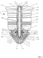
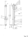
- FIG. 1 shows a first particular embodiment of a plasma burner head 1 according to the present invention.
- Said plasma burner head has an electrode 7, an electrode holder 6, a cooling tube 10, a nozzle 4, a nozzle cap 2 and a gas guide 3.
- the nozzle 4 is fixed by the nozzle cap 2 and a nozzle holder 5.
- the electrode holder 6 receives the electrode 7 and the cooling tube 10 in each case via a thread, namely internal thread 6.4 and internal thread 6.1, on.
- the gas guide 3 is located between the electrode 7 and the nozzle 4 and sets a plasma gas PG in rotation.
- the plasma burner head 1 has a secondary gas protection cap 9, which is screwed onto a nozzle protection cap holder 8 in this exemplary embodiment. Between the secondary gas protection cap 9 and the nozzle cap 2 flows a secondary gas SG, which protects the nozzle 4, in particular the nozzle tip.
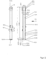
- the cooling tube 10 (see also FIG. 2 ) is attached to the rear part of the electrode holder 6, and the electrode 7 is fixed to the front part of the electrode holder 6.
- the cooling tube 10 projects beyond an area 7.5 extending inwards, ie away from the nozzle tip (see also FIG Figures 3 and 8th In this area, the inner diameter D10.8 along the length L10.8 of the cooling tube 10 is smaller than the inner diameter D10.9 of the rearward inner portion 10.9 of the cooling tube 10 and the outer diameter D10.10 is on the length L10 .10 of the cooling tube 10 is greater than the outer diameter D10.11 of the rearwardly directed outer portion 10.11 of the cooling tube 10.
- a coolant first flows in the flow path through WV1 (water supply 1) the interior of the cooling tube 10, strikes the inwardly extending portion 7.5 of the electrode 7, before it via the flow path WR1 (water return 1) in the space between the cooling tube 10 and the Elek-trode 7 and the electrode holder 6 flows back.
- WV1 water supply 1
- WR1 water return 1
- the plasma jet (not shown) has its starting point on the outer surface of an electrode insert 7.8. There, most of the heat that must be dissipated to achieve a long life of the electrode 7. The heat is conducted via the electrode 7 made of copper or silver to the coolant in the electrode interior.
- the distance between the opposing surfaces of the front inner portion 10.8 of the cooling tube and the electrode portion 7.5 of the electrode 7 and the front outer portion 10.10 and the inner surface 7.10 of the electrode very small. It is in the range of 0.1 to 0.5 mm.
- coolant flows in the space between the nozzle 4 and the nozzle cap 2 via a flow path WV2 (water supply 2) and WR2 (water return 2).
- the cooling tube 10 is screwed to the electrode holder 6 via the external thread 10.1 and the internal thread 6.1.
- the cooling tube 10 and the electrode holder 6 are formed by the cylindrical outer surface 10.3 of the cooling tube 10 and the cylindrical inner surface 6.3 of the electrode holder. 6 centered on each other. These are closely tolerated to each other to achieve a good centering.
- the internal thread 6.1 of the electrode-receiving 6 and the external thread 10.1 of the cooling tube 10 have sufficient clearance to each other, so that the cooling tube 10 can be easily screwed into the electrode holder 6. Only shortly before tightening, the centering is done by the closely tolerated, opposite in the screwed state cylindrical inner surface 6.3 and cylindrical outer surface 10.3.
- the outer diameter D10.3 of the cylindrical outer surface 10.3 of the cooling tube 10 is at least as large as or larger than the outer diameter D10.1 of the external thread 10.1.
- the centering described above ensures the parallel alignment of the cooling tube 10 to the axis M of the plasma burner head 1, a uniform annular gap between the cooling tube 10 and electrode region 7.5 and thus a uniform distribution of the coolant flow in the electrode interior, in particular in the region of the front section 10.8 of the cooling tube 20 and the inwardly extending electrode area 7.5.
- the stop surfaces are 10.2 and 6.2 to each other. This results in an axial fixation of the cooling tube 10 in the electrode holder. 6
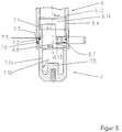
- the electrode 7 is screwed to the electrode holder 6 via the external thread 7.4 and the internal thread 6.4.
- the electrode 7 and the electrode holder 6 are formed by the cylindrical outer surface 7.6 of the electrode 7 and the cylindrical inner surface of the electrode 6.6 6.6 centered to each other.
- the outer surfaces are closely tolerated to each other to achieve a good centering.
- the tolerance of the cylindrical outer surface may be the nominal dimension of the outer diameter D7.6 from 0 to -0.01 mm and the tolerance of the cylindrical inner surface the nominal dimension of the inner diameter D6.6 from 0 to +0.01 mm.
- the internal thread 6.4 of the electrode holder 6 and the external thread 7.4 of the electrode 7 have enough clearance to each other so that the electrode 7 can be easily screwed into the electrode holder 6. Only shortly before tightening the centering is done by the closely tolerated, opposite in the screwed state cylindrical surfaces 6.6 and cylindrical outer surface 7.6.
- the outer diameter D7.6 of the cylindrical outer surface 7.6 of the electrode 7 is at least equal to or greater than the maximum outer diameter D7.4 of the external thread 7.4 (see FIG. 8 ).
- the centering described above is necessary for the parallel alignment of the electrode 6 to the axis M of the plasma burner head 1, which in turn for a uniform distribution of the coolant flow in the electrode interior, in particular in the region of the front inner portion 10.8 of the cooling tube 10 and the inwardly extending portion 7.5 of Electrode 7 provides.
- the centering of the electrode 7 to the electrode holder 6 serves to secure the centricity to the other components of the plasma burner head, in particular the nozzle 4. This is used for uniform formation of the plasma jet, which is determined by positioning the electrode insert 7.8 of the electrode 7 to the nozzle bore 4.1 of the nozzle 4 ,
- the cylindrical outer surface 7.6 has a groove 7.3, in which a round ring 7.2 is arranged for sealing. In the bolted state lie the stop surfaces 7.7 and 6.7 each other. This results in an axial fixation of the electrode 7 in the electrode holder. 6
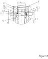
- the projections 10.6 are offset in this case to the projections 10.7 offset by 60 °. This offset improves the radial centering.
- the projections 10.7 can be used as a counterpart for a tool (not shown) for screwing in and out of the cooling tube 10.
- the projections 10.6 and 10.7 have seen from the front portion 10.8 of rectangular cross-section.
- only the corners of the rectangular cross sections are on the cylindrical inner surface 6.11 of the electrode holder 6.
- a high degree of centricity is achieved at the same time smooth assembly.
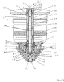
- FIG. 9 shows a further particular embodiment of a plasma burner head 1 according to the invention, which differs from the in the FIGS. 1 to 8 shown embodiment in the design of the front inner portion 10.8 of the cooling tube 10 (see also FIG. 10 ) is different.
- the length L10.8 of the inner section 10.8 is shorter, whereby the flow cross section is greatly increased only in the foremost area.
- the lengths of the front inner section 10.8 and the front outer section 10.10. are the same size here.
- a groove 10.4 in which a circular ring 10.5 is arranged for sealing (see also FIG. 11 ).
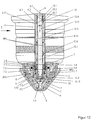
- FIG. 12 shows a further particular embodiment of the plasma burner head according to the invention, which differs from the two embodiments according to the FIGS. 1 to 11 in the design of the front inner portion 10.8 of the cooling tube 10 (see also FIG. 13 ) is different.
- the length L10.8 of the inner section 10.8 is shorter than in the FIG. 1
- the length L10.10 of the front outer section 10.10 is larger than in FIG. 9 .
- the centering between cooling tube 10 and electrode holder 6 also takes place via a cylindrical inner surface 6.3 and a cylindrical outer surface 10.3. But these are different than in the FIGS. 1 and 9 arranged.
- the cylindrical centering surfaces are increased. This further improves the centering and is achieved by changing the order of the threaded centering surface stop surface to the threaded stop surface centering surface. Another advantage is that the size does not increase. With maintained order, the stop surface should have a larger diameter than the centering.
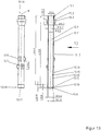
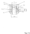
- FIG. 15 shows a further particular embodiment of the plasma burner head according to the invention. This differs from the embodiment according to FIG. 1 in the design of the front inner portion 10.8 of the cooling tube 10 (see also FIG. 16 ).
- the lengths of the front inner section 10.8 and the front outer section 10.10. are the same size here. Said sections correspond in their length to the area 7.5 of the electrode 7.
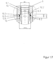
- cooling tube 10 and electrode holder 6 takes place as in FIG. 12 , in the cylindrical outer surface 10.3 of the cooling tube 10, a groove 10.4, in which a round ring is arranged 10.5 for sealing. This is in FIG. 17 shown.
Landscapes
- Physics & Mathematics (AREA)
- Engineering & Computer Science (AREA)
- Plasma & Fusion (AREA)
- Spectroscopy & Molecular Physics (AREA)
- Plasma Technology (AREA)
- Arc Welding In General (AREA)
- Discharge Heating (AREA)
Priority Applications (2)
| Application Number | Priority Date | Filing Date | Title |
|---|---|---|---|
| PL10720245T PL2417840T3 (pl) | 2009-04-08 | 2010-03-24 | Rury chłodzące, uchwyty do elektrod i elektroda do łukowego palnika plazmowego oraz złożone z nich układy i zawierające je łukowy palnik plazmowy |
| SI201031660T SI2417840T1 (en) | 2009-04-08 | 2010-03-24 | Cooling tubes, electrode and electrode holders for an arc plasma torch and assemblies thereof, and an arc plasma burner comprising these elements |
Applications Claiming Priority (2)
| Application Number | Priority Date | Filing Date | Title |
|---|---|---|---|
| DE102009016932A DE102009016932B4 (de) | 2009-04-08 | 2009-04-08 | Kühlrohre und Elektrodenaufnahme für einen Lichtbogenplasmabrenner sowie Anordnungen aus denselben und Lichtbogenplasmabrenner mit denselben |
| PCT/DE2010/000325 WO2010115397A2 (de) | 2009-04-08 | 2010-03-24 | Kühlrohre, elektrodenaufnahmen und elektrode für einen lichtbogenplasmabrenner sowie anordnungen aus denselben und lichtbogenplasmabrenner mit denselben |
Publications (2)
| Publication Number | Publication Date |
|---|---|
| EP2417840A2 EP2417840A2 (de) | 2012-02-15 |
| EP2417840B1 true EP2417840B1 (de) | 2018-02-21 |
Family
ID=42556896
Family Applications (1)
| Application Number | Title | Priority Date | Filing Date |
|---|---|---|---|
| EP10720245.9A Active EP2417840B1 (de) | 2009-04-08 | 2010-03-24 | Kühlrohre, elektrodenaufnahmen und elektrode für einen lichtbogenplasmabrenner sowie anordnungen aus denselben und lichtbogenplasmabrenner mit denselben |
Country Status (12)
| Country | Link |
|---|---|
| US (2) | US9204526B2 (enExample) |
| EP (1) | EP2417840B1 (enExample) |
| JP (1) | JP2012523651A (enExample) |
| KR (1) | KR101650605B1 (enExample) |
| CN (2) | CN102388681A (enExample) |
| BR (1) | BRPI1016021B1 (enExample) |
| DE (1) | DE102009016932B4 (enExample) |
| ES (1) | ES2669644T3 (enExample) |
| PL (1) | PL2417840T3 (enExample) |
| RU (1) | RU2524919C2 (enExample) |
| SI (1) | SI2417840T1 (enExample) |
| WO (1) | WO2010115397A2 (enExample) |
Families Citing this family (21)
| Publication number | Priority date | Publication date | Assignee | Title |
|---|---|---|---|---|
| DE102009016932B4 (de) | 2009-04-08 | 2013-06-20 | Kjellberg Finsterwalde Plasma Und Maschinen Gmbh | Kühlrohre und Elektrodenaufnahme für einen Lichtbogenplasmabrenner sowie Anordnungen aus denselben und Lichtbogenplasmabrenner mit denselben |
| US8633417B2 (en) * | 2010-12-01 | 2014-01-21 | The Esab Group, Inc. | Electrode for plasma torch with novel assembly method and enhanced heat transfer |
| FR2986396A1 (fr) * | 2012-02-01 | 2013-08-02 | Air Liquide | Torche a plasma d'arc avec amelioration du centrage axial de l'electrode |
| EP2642832A1 (de) * | 2012-03-23 | 2013-09-25 | Manfred Hollberg | Plasma-Elektrode für einen Plasmalichtbogenbrenner mit auswechselbarer Elektrodenspitze |
| EP2734015B1 (de) * | 2012-05-07 | 2016-10-19 | Manfred Hollberg | Kühlrohr für einen Plasma-Lichtbogenbrenner |
| JP6082967B2 (ja) | 2012-12-27 | 2017-02-22 | 株式会社小松製作所 | プラズマ切断機および切断方法 |
| WO2016023112A1 (en) * | 2014-08-11 | 2016-02-18 | Best Theratronics Ltd. | System and method for metallic isotope separation by a combined thermal-vacuum distillation process |
| JP1527851S (enExample) * | 2015-01-30 | 2015-06-29 | ||
| JP1527635S (enExample) * | 2015-01-30 | 2015-06-29 | ||
| USD775249S1 (en) * | 2015-04-01 | 2016-12-27 | Koike Sanso Kogyo Co., Ltd. | Inner nozzle for plasma torch |
| EP3716736A1 (en) * | 2015-06-08 | 2020-09-30 | Hypertherm, Inc | Cooling plasma torch nozzles and related systems |
| CN207039985U (zh) | 2016-04-11 | 2018-02-23 | 海别得公司 | 用于液体冷却式等离子体电弧喷枪的等离子气体回旋环 |
| KR20180000059U (ko) | 2016-06-27 | 2018-01-04 | 곽현만 | 플라즈마 토치용 노즐 |
| DE102017112821A1 (de) * | 2017-06-12 | 2018-12-13 | Kjellberg-Stiftung | Elektroden für gas- und flüssigkeitsgekühlte Plasmabrenner, Anordnung aus einer Elektrode und einem Kühlrohr, Gasführung, Plasmabrenner, Verfahren zur Gasführung in einem Plasmabrenner und Verfahren zum Betreiben eines Plasmabrenners |
| CN110014953B (zh) * | 2017-09-30 | 2021-01-19 | 比亚迪股份有限公司 | 第一、第二充电连接件以及充电枪、车辆和充电系统 |
| CA3088556A1 (en) * | 2018-02-20 | 2019-08-29 | Oerlikon Metco (Us) Inc. | Single arc cascaded low pressure coating gun utilizing a neutrode stack as a method of plasma arc control |
| US20220346216A1 (en) * | 2019-09-12 | 2022-10-27 | Kjellberg-Stiftung | Wear Part for an Arc Torch and Plasma Torch, Arc Torch and Plasma Torch Comprising Same, Method for Plasma Cutting and Method for Producing an Electrode for an Arc Torch and Plasma Torch |
| EP4122299A1 (en) * | 2020-03-16 | 2023-01-25 | Hypertherm, Inc. | Liquid coolant tube for a plasma arc cutting system |
| TR202106109A2 (tr) * | 2021-04-06 | 2021-04-21 | Yildirim Ahmet | Sivi soğutmali plazma kesme torcu i̇çi̇n soğutma yüzeyi̇ arttirilmiş elektrot |
| KR102594269B1 (ko) * | 2022-11-17 | 2023-10-26 | (주)한국진공야금 | 플라즈마 토치 |
| DE102023126470A1 (de) * | 2023-09-28 | 2025-04-03 | Comexis GmbH | Anordnung einer Elektrode in einem Plasmabrenner |
Family Cites Families (25)
| Publication number | Priority date | Publication date | Assignee | Title |
|---|---|---|---|---|
| US3408518A (en) * | 1966-10-03 | 1968-10-29 | Strupczewski Andrzej | Composite cathode for use in an arc plasma torch |
| DD87361A1 (de) | 1970-10-23 | 1972-01-20 | Elektrisches Entladungssystem für oxidierende Gase | |
| SU493097A1 (ru) * | 1974-10-28 | 1978-06-25 | Ордена Ленина И Трудового Красного Знамени Институт Электросварки Имени Е.О.Патона | Плазменный резак |
| FR2534106A1 (fr) * | 1982-10-01 | 1984-04-06 | Soudure Autogene Francaise | Torche a plasma monogaz |
| DE3840485A1 (de) * | 1988-12-01 | 1990-06-07 | Mannesmann Ag | Fluessigkeitsgekuehlter plasmabrenner mit uebertragenem lichtbogen |
| GB8904858D0 (en) * | 1989-03-03 | 1989-04-12 | Tetronics Research & Dev Co Li | Improvements in or relating to plasma arc torches |
| US4954688A (en) * | 1989-11-01 | 1990-09-04 | Esab Welding Products, Inc. | Plasma arc cutting torch having extended lower nozzle member |
| US5023425A (en) * | 1990-01-17 | 1991-06-11 | Esab Welding Products, Inc. | Electrode for plasma arc torch and method of fabricating same |
| JPH0490163U (enExample) * | 1990-04-03 | 1992-08-06 | ||
| DE4018423A1 (de) * | 1990-06-08 | 1991-12-12 | Inst Zavaryavane | Plasmatron fuer das brennschneiden von metallen |
| SU1743070A1 (ru) * | 1990-08-13 | 1994-06-15 | Научно-производственное объединение "Научно-исследовательский и конструкторский институт монтажной технологии" | Горелка для плазменной резки |
| FR2674161B1 (fr) * | 1991-03-22 | 1993-06-11 | Soudure Autogene Francaise | Pistolet de decoupage de tole. |
| IT1293298B1 (it) * | 1997-08-06 | 1999-02-16 | Cebora Spa | Perfezionamento di torcia al plasma. |
| FR2772547B1 (fr) | 1997-12-12 | 2000-01-21 | Soudure Autogene Francaise | Ensemble corps d'electrode/porte-electrode pour torche plasma |
| GB2355379A (en) * | 1999-10-12 | 2001-04-18 | Tetronics Ltd | Plasma torch electrode |
| JP2001167898A (ja) * | 1999-12-09 | 2001-06-22 | Nippon Steel Corp | プラズマ加熱用トーチ |
| JP3546947B2 (ja) * | 1999-12-24 | 2004-07-28 | スチールプランテック株式会社 | タンディッシュ内溶鋼加熱用アノードプラズマトーチ |
| JP4216459B2 (ja) * | 2000-12-11 | 2009-01-28 | 新日本製鐵株式会社 | 溶鋼の加熱用プラズマトーチ |
| ITRM20010291A1 (it) * | 2001-05-29 | 2002-11-29 | Ct Sviluppo Materiali Spa | Torcia al plasma |
| JP4653348B2 (ja) * | 2001-07-18 | 2011-03-16 | 新日本製鐵株式会社 | 溶鋼加熱用プラズマトーチ |
| US20080116179A1 (en) * | 2003-04-11 | 2008-05-22 | Hypertherm, Inc. | Method and apparatus for alignment of components of a plasma arc torch |
| US6946617B2 (en) * | 2003-04-11 | 2005-09-20 | Hypertherm, Inc. | Method and apparatus for alignment of components of a plasma arc torch |
| US7081597B2 (en) * | 2004-09-03 | 2006-07-25 | The Esab Group, Inc. | Electrode and electrode holder with threaded connection |
| US7671294B2 (en) * | 2006-11-28 | 2010-03-02 | Vladimir Belashchenko | Plasma apparatus and system |
| DE102009016932B4 (de) | 2009-04-08 | 2013-06-20 | Kjellberg Finsterwalde Plasma Und Maschinen Gmbh | Kühlrohre und Elektrodenaufnahme für einen Lichtbogenplasmabrenner sowie Anordnungen aus denselben und Lichtbogenplasmabrenner mit denselben |
-
2009
- 2009-04-08 DE DE102009016932A patent/DE102009016932B4/de not_active Expired - Fee Related
-
2010
- 2010-03-24 CN CN2010800151938A patent/CN102388681A/zh active Pending
- 2010-03-24 RU RU2011145039/07A patent/RU2524919C2/ru active
- 2010-03-24 KR KR1020117023951A patent/KR101650605B1/ko active Active
- 2010-03-24 ES ES10720245.9T patent/ES2669644T3/es active Active
- 2010-03-24 JP JP2012503857A patent/JP2012523651A/ja active Pending
- 2010-03-24 SI SI201031660T patent/SI2417840T1/en unknown
- 2010-03-24 EP EP10720245.9A patent/EP2417840B1/de active Active
- 2010-03-24 CN CN201710122878.6A patent/CN107018618B/zh not_active Expired - Fee Related
- 2010-03-24 US US13/320,202 patent/US9204526B2/en active Active
- 2010-03-24 PL PL10720245T patent/PL2417840T3/pl unknown
- 2010-03-24 WO PCT/DE2010/000325 patent/WO2010115397A2/de not_active Ceased
- 2010-03-24 BR BRPI1016021-3A patent/BRPI1016021B1/pt not_active IP Right Cessation
-
2014
- 2014-11-25 US US14/553,711 patent/US9743504B2/en active Active
Also Published As
| Publication number | Publication date |
|---|---|
| CN107018618B (zh) | 2020-06-19 |
| CN102388681A (zh) | 2012-03-21 |
| US9204526B2 (en) | 2015-12-01 |
| US9743504B2 (en) | 2017-08-22 |
| SI2417840T1 (en) | 2018-04-30 |
| DE102009016932B4 (de) | 2013-06-20 |
| KR20110136852A (ko) | 2011-12-21 |
| JP2012523651A (ja) | 2012-10-04 |
| WO2010115397A3 (de) | 2011-03-03 |
| PL2417840T3 (pl) | 2018-07-31 |
| BRPI1016021B1 (pt) | 2019-11-19 |
| DE102009016932A1 (de) | 2010-10-21 |
| US20150083695A1 (en) | 2015-03-26 |
| RU2011145039A (ru) | 2013-05-20 |
| US20120132626A1 (en) | 2012-05-31 |
| RU2524919C2 (ru) | 2014-08-10 |
| BRPI1016021A2 (pt) | 2016-04-26 |
| CN107018618A (zh) | 2017-08-04 |
| KR101650605B1 (ko) | 2016-08-23 |
| ES2669644T3 (es) | 2018-05-28 |
| EP2417840A2 (de) | 2012-02-15 |
| WO2010115397A2 (de) | 2010-10-14 |
Similar Documents
| Publication | Publication Date | Title |
|---|---|---|
| EP2417840B1 (de) | Kühlrohre, elektrodenaufnahmen und elektrode für einen lichtbogenplasmabrenner sowie anordnungen aus denselben und lichtbogenplasmabrenner mit denselben | |
| EP2140739B1 (de) | Düse für einen flüssigkeitsgekühlten plasmabrenner, anordnung aus derselben und einer düsenkappe sowie flüssigkeitsgekühlter plasmabrenner mit einer derartigen anordnung | |
| EP2175702B9 (de) | Düse und Düsenkappe für einen flüssigkeitsgekühlten Plasmabrenner sowie Plasmabrennerkopf mit derselben/denselben | |
| DE102008062731B9 (de) | Elektrode für einen Plasmabrenner | |
| EP2449862B1 (de) | Düse für einen flüssigkeitsgekühlten plasmabrenner sowie plasmabrennerkopf mit derselben | |
| EP2804450B1 (de) | Mehrteiliges Isolierteil für einen Lichtbogenplasmabrenner, Brenner und zugehörige Anordnungen mit demselben und zugehörigen Verfahren | |
| EP0585203A1 (de) | Plasmaspritzgerät | |
| DE202009018173U1 (de) | Düsenschutzkappe und Düsenschutzkappenhalter sowie Lichtbogenplasmabrenner mit derselben und/oder demselben | |
| EP2849542B1 (de) | Elektrodenaufbau für Plasmaschneidbrenner | |
| EP2667689B1 (de) | Elektrode für Plasmaschneidbrenner sowie deren Verwendung | |
| DE102010053721B4 (de) | Brenner für das Wolfram-Inertgas-Schweißen sowie Elektrode zur Verwendung bei einem solchen Brenner | |
| EP2168409A1 (de) | Vorrichtung zur erzeugung eines plasma-jets | |
| DE102018125772A1 (de) | Verbindungsteil für einen Bearbeitungskopf zur thermischen Materialbearbeitung, insbesondere für einen Plasmabrennerkopf, Laserkopf, Plasma-Laser-Kopf sowie ein Verschleißteil und eine Verschleißteilhalterung und ein Verfahren zum Fügen dieser | |
| DE102009031857C5 (de) | Düse für einen flüssigkeitsgekühlten Plasmabrenner sowie Plasmabrennerkopf mit derselben | |
| EP0849026A1 (de) | Schutzgasschweissbrenner | |
| DE102009060849A1 (de) | Düse für einen flüssigkeitsgekühlten Plasmabrenner sowie Plasmabrennerkopf mit derselben | |
| DE1564123A1 (de) | Einrichtung zum Erzeugen eines heissen Plasmastrahles | |
| DE19825555A1 (de) | Lichtbogen-Plasmagenerator | |
| DE9218876U1 (de) | Plasmaspritzgerät | |
| WO2022028648A1 (de) | Elektrode für einen plasmaschneidbrenner, anordnung mit derselben, plasmaschneidbrenner mit derselben sowie verfahren zum plasmaschneiden |
Legal Events
| Date | Code | Title | Description |
|---|---|---|---|
| PUAI | Public reference made under article 153(3) epc to a published international application that has entered the european phase |
Free format text: ORIGINAL CODE: 0009012 |
|
| 17P | Request for examination filed |
Effective date: 20110913 |
|
| AK | Designated contracting states |
Kind code of ref document: A2 Designated state(s): AT BE BG CH CY CZ DE DK EE ES FI FR GB GR HR HU IE IS IT LI LT LU LV MC MK MT NL NO PL PT RO SE SI SK SM TR |
|
| DAX | Request for extension of the european patent (deleted) | ||
| RAP1 | Party data changed (applicant data changed or rights of an application transferred) |
Owner name: KJELLBERG FINSTERWALDE PLASMA UND MASCHINEN GMBH |
|
| 17Q | First examination report despatched |
Effective date: 20151126 |
|
| RAP1 | Party data changed (applicant data changed or rights of an application transferred) |
Owner name: KJELLBERG FINSTERWALDE PLASMA UND MASCHINEN GMBH |
|
| GRAP | Despatch of communication of intention to grant a patent |
Free format text: ORIGINAL CODE: EPIDOSNIGR1 |
|
| INTG | Intention to grant announced |
Effective date: 20170313 |
|
| GRAJ | Information related to disapproval of communication of intention to grant by the applicant or resumption of examination proceedings by the epo deleted |
Free format text: ORIGINAL CODE: EPIDOSDIGR1 |
|
| GRAP | Despatch of communication of intention to grant a patent |
Free format text: ORIGINAL CODE: EPIDOSNIGR1 |
|
| INTG | Intention to grant announced |
Effective date: 20170914 |
|
| GRAS | Grant fee paid |
Free format text: ORIGINAL CODE: EPIDOSNIGR3 |
|
| GRAA | (expected) grant |
Free format text: ORIGINAL CODE: 0009210 |
|
| AK | Designated contracting states |
Kind code of ref document: B1 Designated state(s): AT BE BG CH CY CZ DE DK EE ES FI FR GB GR HR HU IE IS IT LI LT LU LV MC MK MT NL NO PL PT RO SE SI SK SM TR |
|
| REG | Reference to a national code |
Ref country code: GB Ref legal event code: FG4D Free format text: NOT ENGLISH |
|
| REG | Reference to a national code |
Ref country code: CH Ref legal event code: EP |
|
| REG | Reference to a national code |
Ref country code: AT Ref legal event code: REF Ref document number: 973088 Country of ref document: AT Kind code of ref document: T Effective date: 20180315 |
|
| REG | Reference to a national code |
Ref country code: IE Ref legal event code: FG4D Free format text: LANGUAGE OF EP DOCUMENT: GERMAN |
|
| REG | Reference to a national code |
Ref country code: DE Ref legal event code: R096 Ref document number: 502010014670 Country of ref document: DE |
|
| REG | Reference to a national code |
Ref country code: FR Ref legal event code: PLFP Year of fee payment: 9 |
|
| REG | Reference to a national code |
Ref country code: NL Ref legal event code: FP |
|
| REG | Reference to a national code |
Ref country code: ES Ref legal event code: FG2A Ref document number: 2669644 Country of ref document: ES Kind code of ref document: T3 Effective date: 20180528 |
|
| REG | Reference to a national code |
Ref country code: SK Ref legal event code: T3 Ref document number: E 26888 Country of ref document: SK |
|
| REG | Reference to a national code |
Ref country code: LT Ref legal event code: MG4D |
|
| PG25 | Lapsed in a contracting state [announced via postgrant information from national office to epo] |
Ref country code: NO Free format text: LAPSE BECAUSE OF FAILURE TO SUBMIT A TRANSLATION OF THE DESCRIPTION OR TO PAY THE FEE WITHIN THE PRESCRIBED TIME-LIMIT Effective date: 20180521 Ref country code: CY Free format text: LAPSE BECAUSE OF FAILURE TO SUBMIT A TRANSLATION OF THE DESCRIPTION OR TO PAY THE FEE WITHIN THE PRESCRIBED TIME-LIMIT Effective date: 20180221 Ref country code: HR Free format text: LAPSE BECAUSE OF FAILURE TO SUBMIT A TRANSLATION OF THE DESCRIPTION OR TO PAY THE FEE WITHIN THE PRESCRIBED TIME-LIMIT Effective date: 20180221 Ref country code: LT Free format text: LAPSE BECAUSE OF FAILURE TO SUBMIT A TRANSLATION OF THE DESCRIPTION OR TO PAY THE FEE WITHIN THE PRESCRIBED TIME-LIMIT Effective date: 20180221 Ref country code: FI Free format text: LAPSE BECAUSE OF FAILURE TO SUBMIT A TRANSLATION OF THE DESCRIPTION OR TO PAY THE FEE WITHIN THE PRESCRIBED TIME-LIMIT Effective date: 20180221 |
|
| PG25 | Lapsed in a contracting state [announced via postgrant information from national office to epo] |
Ref country code: GR Free format text: LAPSE BECAUSE OF FAILURE TO SUBMIT A TRANSLATION OF THE DESCRIPTION OR TO PAY THE FEE WITHIN THE PRESCRIBED TIME-LIMIT Effective date: 20180522 Ref country code: LV Free format text: LAPSE BECAUSE OF FAILURE TO SUBMIT A TRANSLATION OF THE DESCRIPTION OR TO PAY THE FEE WITHIN THE PRESCRIBED TIME-LIMIT Effective date: 20180221 Ref country code: SE Free format text: LAPSE BECAUSE OF FAILURE TO SUBMIT A TRANSLATION OF THE DESCRIPTION OR TO PAY THE FEE WITHIN THE PRESCRIBED TIME-LIMIT Effective date: 20180221 Ref country code: BG Free format text: LAPSE BECAUSE OF FAILURE TO SUBMIT A TRANSLATION OF THE DESCRIPTION OR TO PAY THE FEE WITHIN THE PRESCRIBED TIME-LIMIT Effective date: 20180521 |
|
| PG25 | Lapsed in a contracting state [announced via postgrant information from national office to epo] |
Ref country code: MT Free format text: LAPSE BECAUSE OF FAILURE TO SUBMIT A TRANSLATION OF THE DESCRIPTION OR TO PAY THE FEE WITHIN THE PRESCRIBED TIME-LIMIT Effective date: 20180221 |
|
| PG25 | Lapsed in a contracting state [announced via postgrant information from national office to epo] |
Ref country code: RO Free format text: LAPSE BECAUSE OF FAILURE TO SUBMIT A TRANSLATION OF THE DESCRIPTION OR TO PAY THE FEE WITHIN THE PRESCRIBED TIME-LIMIT Effective date: 20180221 Ref country code: EE Free format text: LAPSE BECAUSE OF FAILURE TO SUBMIT A TRANSLATION OF THE DESCRIPTION OR TO PAY THE FEE WITHIN THE PRESCRIBED TIME-LIMIT Effective date: 20180221 |
|
| REG | Reference to a national code |
Ref country code: CH Ref legal event code: PL |
|
| REG | Reference to a national code |
Ref country code: DE Ref legal event code: R097 Ref document number: 502010014670 Country of ref document: DE |
|
| PG25 | Lapsed in a contracting state [announced via postgrant information from national office to epo] |
Ref country code: SM Free format text: LAPSE BECAUSE OF FAILURE TO SUBMIT A TRANSLATION OF THE DESCRIPTION OR TO PAY THE FEE WITHIN THE PRESCRIBED TIME-LIMIT Effective date: 20180221 Ref country code: DK Free format text: LAPSE BECAUSE OF FAILURE TO SUBMIT A TRANSLATION OF THE DESCRIPTION OR TO PAY THE FEE WITHIN THE PRESCRIBED TIME-LIMIT Effective date: 20180221 Ref country code: MC Free format text: LAPSE BECAUSE OF FAILURE TO SUBMIT A TRANSLATION OF THE DESCRIPTION OR TO PAY THE FEE WITHIN THE PRESCRIBED TIME-LIMIT Effective date: 20180221 |
|
| REG | Reference to a national code |
Ref country code: IE Ref legal event code: MM4A |
|
| PLBE | No opposition filed within time limit |
Free format text: ORIGINAL CODE: 0009261 |
|
| STAA | Information on the status of an ep patent application or granted ep patent |
Free format text: STATUS: NO OPPOSITION FILED WITHIN TIME LIMIT |
|
| PG25 | Lapsed in a contracting state [announced via postgrant information from national office to epo] |
Ref country code: LU Free format text: LAPSE BECAUSE OF NON-PAYMENT OF DUE FEES Effective date: 20180324 |
|
| 26N | No opposition filed |
Effective date: 20181122 |
|
| GBPC | Gb: european patent ceased through non-payment of renewal fee |
Effective date: 20180521 |
|
| PG25 | Lapsed in a contracting state [announced via postgrant information from national office to epo] |
Ref country code: IE Free format text: LAPSE BECAUSE OF NON-PAYMENT OF DUE FEES Effective date: 20180324 |
|
| PG25 | Lapsed in a contracting state [announced via postgrant information from national office to epo] |
Ref country code: LI Free format text: LAPSE BECAUSE OF NON-PAYMENT OF DUE FEES Effective date: 20180331 Ref country code: CH Free format text: LAPSE BECAUSE OF NON-PAYMENT OF DUE FEES Effective date: 20180331 |
|
| PG25 | Lapsed in a contracting state [announced via postgrant information from national office to epo] |
Ref country code: GB Free format text: LAPSE BECAUSE OF NON-PAYMENT OF DUE FEES Effective date: 20180521 |
|
| REG | Reference to a national code |
Ref country code: AT Ref legal event code: MM01 Ref document number: 973088 Country of ref document: AT Kind code of ref document: T Effective date: 20180324 |
|
| PG25 | Lapsed in a contracting state [announced via postgrant information from national office to epo] |
Ref country code: AT Free format text: LAPSE BECAUSE OF NON-PAYMENT OF DUE FEES Effective date: 20180324 |
|
| PG25 | Lapsed in a contracting state [announced via postgrant information from national office to epo] |
Ref country code: TR Free format text: LAPSE BECAUSE OF FAILURE TO SUBMIT A TRANSLATION OF THE DESCRIPTION OR TO PAY THE FEE WITHIN THE PRESCRIBED TIME-LIMIT Effective date: 20180221 |
|
| PG25 | Lapsed in a contracting state [announced via postgrant information from national office to epo] |
Ref country code: HU Free format text: LAPSE BECAUSE OF FAILURE TO SUBMIT A TRANSLATION OF THE DESCRIPTION OR TO PAY THE FEE WITHIN THE PRESCRIBED TIME-LIMIT; INVALID AB INITIO Effective date: 20100324 Ref country code: PT Free format text: LAPSE BECAUSE OF FAILURE TO SUBMIT A TRANSLATION OF THE DESCRIPTION OR TO PAY THE FEE WITHIN THE PRESCRIBED TIME-LIMIT Effective date: 20180221 |
|
| PG25 | Lapsed in a contracting state [announced via postgrant information from national office to epo] |
Ref country code: MK Free format text: LAPSE BECAUSE OF NON-PAYMENT OF DUE FEES Effective date: 20180221 |
|
| PG25 | Lapsed in a contracting state [announced via postgrant information from national office to epo] |
Ref country code: IS Free format text: LAPSE BECAUSE OF FAILURE TO SUBMIT A TRANSLATION OF THE DESCRIPTION OR TO PAY THE FEE WITHIN THE PRESCRIBED TIME-LIMIT Effective date: 20180621 |
|
| PGFP | Annual fee paid to national office [announced via postgrant information from national office to epo] |
Ref country code: SK Payment date: 20220314 Year of fee payment: 13 Ref country code: NL Payment date: 20220322 Year of fee payment: 13 Ref country code: FR Payment date: 20220322 Year of fee payment: 13 Ref country code: BE Payment date: 20220322 Year of fee payment: 13 |
|
| PGFP | Annual fee paid to national office [announced via postgrant information from national office to epo] |
Ref country code: SI Payment date: 20220315 Year of fee payment: 13 |
|
| PGFP | Annual fee paid to national office [announced via postgrant information from national office to epo] |
Ref country code: IT Payment date: 20220331 Year of fee payment: 13 Ref country code: ES Payment date: 20220420 Year of fee payment: 13 |
|
| PGFP | Annual fee paid to national office [announced via postgrant information from national office to epo] |
Ref country code: PL Payment date: 20220317 Year of fee payment: 13 |
|
| REG | Reference to a national code |
Ref country code: SK Ref legal event code: MM4A Ref document number: E 26888 Country of ref document: SK Effective date: 20230324 Ref country code: NL Ref legal event code: MM Effective date: 20230401 |
|
| REG | Reference to a national code |
Ref country code: BE Ref legal event code: MM Effective date: 20230331 |
|
| PG25 | Lapsed in a contracting state [announced via postgrant information from national office to epo] |
Ref country code: NL Free format text: LAPSE BECAUSE OF NON-PAYMENT OF DUE FEES Effective date: 20230401 |
|
| PG25 | Lapsed in a contracting state [announced via postgrant information from national office to epo] |
Ref country code: SK Free format text: LAPSE BECAUSE OF NON-PAYMENT OF DUE FEES Effective date: 20230324 |
|
| PG25 | Lapsed in a contracting state [announced via postgrant information from national office to epo] |
Ref country code: SK Free format text: LAPSE BECAUSE OF NON-PAYMENT OF DUE FEES Effective date: 20230324 Ref country code: SI Free format text: LAPSE BECAUSE OF NON-PAYMENT OF DUE FEES Effective date: 20230325 Ref country code: FR Free format text: LAPSE BECAUSE OF NON-PAYMENT OF DUE FEES Effective date: 20230331 |
|
| REG | Reference to a national code |
Ref country code: SI Ref legal event code: KO00 Effective date: 20231201 |
|
| PG25 | Lapsed in a contracting state [announced via postgrant information from national office to epo] |
Ref country code: BE Free format text: LAPSE BECAUSE OF NON-PAYMENT OF DUE FEES Effective date: 20230331 |
|
| PG25 | Lapsed in a contracting state [announced via postgrant information from national office to epo] |
Ref country code: IT Free format text: LAPSE BECAUSE OF NON-PAYMENT OF DUE FEES Effective date: 20230324 |
|
| REG | Reference to a national code |
Ref country code: ES Ref legal event code: FD2A Effective date: 20240507 |
|
| PG25 | Lapsed in a contracting state [announced via postgrant information from national office to epo] |
Ref country code: ES Free format text: LAPSE BECAUSE OF NON-PAYMENT OF DUE FEES Effective date: 20230325 |
|
| PG25 | Lapsed in a contracting state [announced via postgrant information from national office to epo] |
Ref country code: ES Free format text: LAPSE BECAUSE OF NON-PAYMENT OF DUE FEES Effective date: 20230325 |
|
| PG25 | Lapsed in a contracting state [announced via postgrant information from national office to epo] |
Ref country code: PL Free format text: LAPSE BECAUSE OF NON-PAYMENT OF DUE FEES Effective date: 20230324 |
|
| PG25 | Lapsed in a contracting state [announced via postgrant information from national office to epo] |
Ref country code: PL Free format text: LAPSE BECAUSE OF NON-PAYMENT OF DUE FEES Effective date: 20230324 |
|
| REG | Reference to a national code |
Ref country code: DE Ref legal event code: R082 Ref document number: 502010014670 Country of ref document: DE Representative=s name: BOEHMERT & BOEHMERT ANWALTSPARTNERSCHAFT MBB -, DE |
|
| PGFP | Annual fee paid to national office [announced via postgrant information from national office to epo] |
Ref country code: DE Payment date: 20250327 Year of fee payment: 16 |
|
| PGFP | Annual fee paid to national office [announced via postgrant information from national office to epo] |
Ref country code: CZ Payment date: 20250307 Year of fee payment: 16 |