EP2412083B1 - Antriebseinrichtung - Google Patents
Antriebseinrichtung Download PDFInfo
- Publication number
- EP2412083B1 EP2412083B1 EP10704829.0A EP10704829A EP2412083B1 EP 2412083 B1 EP2412083 B1 EP 2412083B1 EP 10704829 A EP10704829 A EP 10704829A EP 2412083 B1 EP2412083 B1 EP 2412083B1
- Authority
- EP
- European Patent Office
- Prior art keywords
- electric machine
- channel
- shaft
- liquid
- rotor
- Prior art date
- Legal status (The legal status is an assumption and is not a legal conclusion. Google has not performed a legal analysis and makes no representation as to the accuracy of the status listed.)
- Active
Links
Images


Classifications
-
- H—ELECTRICITY
- H02—GENERATION; CONVERSION OR DISTRIBUTION OF ELECTRIC POWER
- H02K—DYNAMO-ELECTRIC MACHINES
- H02K9/00—Arrangements for cooling or ventilating
- H02K9/19—Arrangements for cooling or ventilating for machines with closed casing and closed-circuit cooling using a liquid cooling medium, e.g. oil
-
- H—ELECTRICITY
- H02—GENERATION; CONVERSION OR DISTRIBUTION OF ELECTRIC POWER
- H02K—DYNAMO-ELECTRIC MACHINES
- H02K1/00—Details of the magnetic circuit
- H02K1/06—Details of the magnetic circuit characterised by the shape, form or construction
- H02K1/22—Rotating parts of the magnetic circuit
- H02K1/32—Rotating parts of the magnetic circuit with channels or ducts for flow of cooling medium
Definitions
- the present invention relates to an electric machine according to the preamble of claim 1 and a drive device according to the preamble of claim 14.
- Drive devices preferably hybrid drive devices, in particular with an internal combustion engine, and an electric machine are used, for example, to drive motor vehicles.
- the functioning as a motor and generator electric machine in the motor vehicle has an axis or shaft with a stator or rotor disposed thereon.
- the stator and the rotor of the electric machine are cooled by a cooling circuit by means of oil.
- the shaft is generally in two parts and consists of a rotor shaft with an axial bore and an inner shaft.
- the inner shaft is arranged, wherein between the inner shaft and the rotor shaft, a circular cross-section gap is formed. Through this gap, the oil is passed to cool.
- a balance disk is arranged at the rotor shaft.
- the rotor shaft and the balance disk are provided with radial passages through which the oil for cooling out of the gap in the radial direction is directed outward. Due to the rotational movement of the rotor shaft and the balance disk, the channel acts as a pump.
- the oil exits at the end of the channels from outlet openings and thereby cools the stator and the rotor of the electric machine.
- the oil is also fed by an additional pump from an oil sump as a coolant circuit in the gap. This pump, which removes the oil from the Pump sump promotes the oil also pumps to other components of the drive device, which must be cooled and / or lubricated, z.
- the DE 10 2006 008 049 A1 shows a drive unit comprising: an engine room in which a stator and a rotor are accommodated; a gear room provided in the direction of the rotation axis of the rotor adjacent to the engine compartment and accommodating a transmission, wherein the rotation of the rotor is transmitted to the transmission; a bearing for supporting the rotation of both the rotor and the transmission; and a wall disposed between the engine room and the gear room to support the bearing, the wall being provided with an opening for injecting lubricating oil splashed from the transmission onto an upper portion of the stator.
- the DE 102 38 023 B4 shows an internal combustion engine including a generator or motor, the stator of which comprises a core and coils attached to the core, and which stator faces permanent magnets attached to a crankshaft of the internal combustion engine, the internal combustion engine further comprising stator cooling means for cooling the stator with oil wherein the permanent magnets are mounted on the outer circumference of a crank arm of the crankshaft and that the stator arcuately surrounds the crankshaft carrying the permanent magnets on the side remote from the cylinder block.
- the DE 199 28 247 B4 shows a motor comprising a motor housing, a stator of cylindrical shape, which is fixed to the motor housing, an inner A rotor rotatably disposed within the stator, an outer rotor rotatably disposed about the stator, wherein the inner rotor, the stator and the outer rotor are concentrically arranged and a plurality of bolts for fixing the stator to the motor housing, wherein a cooling system is provided , a plurality of pairs of cooling channels formed in the stator, a coolant inlet port for introducing coolant into the cooling channels, a coolant outlet port for discharging coolant from the cooling channels, the coolant inlet port and the coolant outlet port being provided at an axial end of the inner rotor and are connected to the cooling channels, adeschschreibmannmannmannmannmannabterrorism for connecting each pair of cooling channels, wherein thedestoffmannmaschinenabterrorism is provided in another axial end of the inner rotor, and wherein the cooling channels
- the DE 2240797 discloses a rotor of an electric machine having a radially oriented channel in which liquid can be conveyed.
- the radially directed channel has an outlet opening for discharging the liquid, in which a means for reducing the flow rate is arranged.
- An electric machine in particular for a motor vehicle, comprising a housing, at least one shaft, a stator and a rotor, a cooling circuit for cooling the electric machine with a liquid, in particular oil, wherein the liquid of at least one at least partially radially oriented channel in at least one rotating part of the electric machine is due to a rotational movement of the at least one channel, at least one outlet opening for discharging the liquid from the at least one channel, wherein the electric machine with at least one means for reducing the flow rate per unit time of liquid which is provided by the at least one channel due to the rotational movement of the at least one channel, is provided.
- the at least one means reduces the flow rate per unit time of liquid conveyed by the at least one channel.
- the cooling circuit can also be used to uniformly cool other components of the drive device and / or lubricate.
- a high rotational speed of the rotating part thus does not cause larger quantities of oil to be drawn off from the cooling circuit, so that not enough oil is available for cooling and / or for lubricating other components of the drive device.
- the at least one rotating part is the at least one shaft and / or a balancing disk.
- the at least one shaft comprises a rotor shaft with an axial bore and an inner shaft, wherein the inner shaft is arranged in the axial bore of the rotor shaft.
- the rotor shafts and the inner shaft are positively, for. B. by means of a toothing, connected to each other, so that the rotor shafts and the inner shaft have the same speed and torques between the rotor shaft and the inner shaft can be transmitted.
- the cooling circuit is provided with a pump for additional delivery of the liquid, preferably from a sump.
- the pump which does not constitute the at least one radially directed channel, conveys the oil to the at least one channel and preferably to other components to be cooled and / or lubricated, e.g. B. a differential gear and / or a transmission and / or the internal combustion engine.
- the at least one means comprises at least one air intake opening, wherein the at least one air intake opening is fluid-conductively connected to the at least one channel for reducing the delivery rate per unit time of liquid.
- the at least one air intake opening is expediently formed radially inside the at least one outlet opening and / or the at least one air intake opening is formed in the rotating part.
- the at least one Air intake opening thus has a smaller distance to an axis of the shaft than the at least one outlet opening.
- the at least one means is designed such that the reduction of the flow rate per unit time of liquid due to the rotational movement of the at least one channel in dependence on the rotational speed of the rotating part, in particular the at least one shaft, in particular by a flow cross-sectional area of the at least one channel is changeable.
- the reduction of the flow rate per unit time of liquid is indirectly proportional to the speed of rotation of the rotating part, i. H. the higher the rotational speed of the rotating part, the greater the reduction of the flow rate per unit time of liquid due to the rotational movement of the at least one channel.
- the reduction is caused by the at least one agent.
- the reduction is the difference between the flow rate per unit time of fluid in the electric machine with and without the at least one means.
- the at least one means comprises at least one at least partially radially movable radial throttle element, wherein the at least one radial throttle element is movable into the at least one channel by means of a centrifugal force such that the greater the centrifugal force, the smaller the flow cross-sectional area of the at least one channel becomes.
- the at least one means comprises at least one elastic element, for. B. a spring to move the at least one radial throttle element at a decreasing centrifugal force, so that the flow cross-sectional area of the at least one channel is increased with a decreasing centrifugal force.
- the at least one radial throttle element and / or the at least one elastic element in the rotating part for. B. the balancing wheel arranged.
- the at least one means comprises at least one tangential throttle element which can be moved at least partially in the tangential direction, wherein the tangential throttle element is movable into the at least one channel by means of an inertial force or tangential force so that the greater the rotational speed of the at least one tangential throttle element, the smaller the flow cross-sectional area of the at least one channel is and vice versa.
- the at least one means comprises at least one elastic element, e.g. B. a spring to move the at least one Tangentialdrosselelement at a decreasing inertial force or tangential out of the at least one channel, so that the flow cross-sectional area of the at least one channel is increased.
- at least one elastic element e.g. B. a spring to move the at least one Tangentialdrosselelement at a decreasing inertial force or tangential out of the at least one channel, so that the flow cross-sectional area of the at least one channel is increased.
- this is at least one Tangentialdrosselelement and / or the at least one elastic element in the rotating part, for. B. the balancing wheel arranged.
- a drive device in particular for a motor vehicle, preferably comprises an internal combustion engine, in particular for driving the motor vehicle, preferably at least one housing, at least one, preferably in the at least one housing arranged electric machine with a stator and a rotor, wherein the at least an electric machine is designed according to an electric machine described in this patent application.
- the at least one housing is multi-part.
- the housing is in one piece.
- the at least one electric machine acts as a motor and / or as a generator.
- a motor vehicle according to the invention comprises at least one electric machine described in this application and / or at least one drive device described in this application.
- the motor vehicle comprises rechargeable batteries.
- the batteries supply electric power to the electric machine, and when decelerating the motor vehicle by means of the electric machine, the batteries can be charged by the electric power generated by the electric machine.
- the batteries can also be charged during a standstill of the motor vehicle, for example, from a public power grid.
- the batteries are designed as lithium-ion batteries.
- a hybrid drive device 2 formed drive device 1 for a motor vehicle 3 is shown.
- the hybrid drive device 2 for a motor vehicle 3 includes an internal combustion engine 4 and an electric machine 5, which functions as a motor 32 and generator 33, respectively for driving or decelerating the motor vehicle 3.
- the internal combustion engine 4 and the electric machine 5 are interconnected by means of a drive shaft 20.
- the mechanical coupling between the internal combustion engine 4 and the electric machine 5 can be produced and canceled by means of a coupling 19.
- an elasticity 21 is arranged in the drive shaft 20, which couples the internal combustion engine 4 and the electric machine 5 together.
- the electric machine 5 is mechanically coupled to a differential gear 23.
- a converter 22 and a gear 28 is arranged in the drive shaft 20, which connects the electric machine 5 and the differential gear 23 with each other.
- the drive wheels 25 are driven via the wheel axles 24.
- the electric machine 5 may be arranged laterally on the internal combustion engine 4 and mechanically connected by means of a belt or a chain or gears with the internal combustion engine 4 instead of in Fig. 1 illustrated drive shaft 20 (not shown).
- the electric machine 5 could be connected to a transmission, for. B. a differential, be arranged or the electric machine 5 can act as a wheel hub motor and / or as a hub generator, ie be arranged in the region of a wheel hub (not shown).
- Fig. 2 shows the electric machine 5 for the hybrid drive device 2 as êtpolmaschine in a first embodiment with a fixed stator 6 and a rotating rotor 7 of the hybrid drive device 1 in a much simplified representation, so that, for example, electrical lines, the windings of the stator 6 and the rotor 7, and Fixing means for the stator 6 are not shown or only greatly simplified.
- a shaft 8 is made of metal, for. As steel, on which the rotor 7 is arranged concentrically, wherein the shaft 8 and the rotor 7 are mounted by means of a bearing 39 to a fixed housing 9. Concentrically around the rotor 7, the stator 6 is arranged on the housing 9, which is fastened thereto by means of fixing means (not shown).
- the stator 6 may be attached to the housing 9 without additional fixing means, for. B. by means of pressing compound and / or shrinkage composite.
- the shaft 8 is connected within the hybrid drive device 2 with the drive shaft 20 of the hybrid drive device 2 and constitutes a part of the drive shaft 20.
- the shaft 8 of the electric machine 5 consists of an inner shaft 17 and a rotor shaft 16.
- the rotor shaft 16 is provided with an axial bore 18 in which the inner shaft 17 is arranged. Between the inner shaft 17 and the rotor shaft 16 is formed due to the geometry of the axial bore 18 and the diameter of the inner shaft 17 is a circular cross-section gap 26.
- the rotor shaft 16 and the inner shaft 17 are rotating parts 12 of the electric machine 5, which around the Rotate shaft 37 of the shaft 8 and the rotor shaft 16 and the inner shaft 17.
- the rotor shaft 16 is provided with radial channels 11 (in Fig. 2 only one channel 11 is shown).
- the balance disk 15 On the rotor shaft 16, a balance disk 15 is further arranged.
- the balance disk 15 has the task of preventing imbalances on the rotor 7 and also to promote and distribute oil for cooling.
- the balancing wheel 15 ( FIGS. 2 and 3 ) also has radially aligned channels 11 which, viewed at the radially inner end, have outlet openings 13 in inlet openings 38 and at the radially outer end.
- cooling circuit 10 with a pump 27 and a pump sump 29, a liquid, in particular oil, for cooling the stator 6 and the rotor 7 is introduced into the gap 26.
- the oil flows out of the gap 26 through the incorporated into the rotor shaft 16 channels 11 and then through the incorporated into the balance disk 15 channels 11.
- the oil thus flows from the channels 11 of the rotor shaft 16 through the inlet openings 38 into the channels 11 of the balancing disk 15 and exits at the outlet openings 13 of the balancing disk 15 again and is sprayed onto the stator 6 as well as on the rotor 7 for cooling the stator 6 and the rotor 7.
- the sprayed oil collects again in a collecting area, not shown, and is also in the not in Fig. 2 passed pump sump 29 shown.
- the rotor shaft 16 and the balancing disk 15 as rotating parts 12 with the thus also rotating channels 11 have a suction effect due to the forces acting in the channels 11 centrifugal forces, so that they can produce a negative pressure in the cooling circuit 10.
- the balancing wheel 15 has an annular air intake opening 30, so that a reduction in the negative pressure in the channels 11 occurs during the transition of the oil flowing through the channels 11 of the rotor shaft 16 on the balance disk 15, because the air intake opening 30 is connected to the atmospheric pressure and As a result, air can flow into the channels 11 in the region between the balancing disk 15 and the rotor shaft 16. As a result, the suction effect of the channels 11 in the balancing disc 15 is substantially reduced, so that even at very high rotational speeds of the rotating parts 12 of the electric machine 5 of the channels 11 only a slight negative pressure is generated. As a result, a strong negative pressure can be avoided within the cooling circuit 10, not shown.
- the cooling circuit 10 Furthermore, at high rotational speeds of the rotating parts 12, not too large amounts of oil are sucked out of the cooling circuit 10, so that upon integration of the electric machine 5 into the drive device 1, further components of the drive device 1, which cool from the oil and / or to lubricate, enough oil is available for cooling. In this case, the oil is further directed to the desired surfaces, ie the end face of the rotor 7 and the winding heads of the stator 6, which are to be cooled by the oil, because the outlet openings 13 are unchanged.
- the air intake 30 is thus a means 14 for reducing the flow rate per unit time of oil. Due to the integration the air intake opening 30 in the balancing disk 15 is advantageously no additional space for the means 14 for reducing the flow rate of oil needed.
- FIG. 4 an exemplary electric machine 5 is shown.
- the electric machine 5 has analogous to the first embodiment according to FIGS. 2 and 3 a consisting of the inner shaft 17 and the rotor shaft 16 shaft 8, wherein between the inner shaft 17 and the rotor shaft 16, the gap 26 for passing oil is provided as a cooling fluid.
- the oil is directed into the gap 26 by means of the pump 27 from the pump sump 29 through oil lines 41 into the gap 26. From a catchment area, not shown, the oil is returned by means not shown manifolds to the pump sump 29 so that the cooling circuit 10 is formed for cooling by means of oil.
- the stator 6, the rotor 7 and the housing 9 of the electric machine 5 are not shown.
- tangential recesses 40 are incorporated on the inside in the region of the axial bore.
- Tangentialdrosselemia 36 are not shown by guide means, for. B. a plain bearing by means of a groove and spring connection (not shown) of the tangential throttling elements 36, guided in the tangential recess 40 and are thus movable in the tangential direction in the tangential recesses 40.
- Radial channels 11 are incorporated in the rotor shaft 16 as well as in the balancing disk 15 arranged above it Fig. 4 are shown in dashed lines.
- the oil thus flows through the gap 26 and through the channels 11 and exits at the outlet openings 13 on the balancing disk 15 for cooling the stator 6 not shown in the figure and the rotor 7.
- the rotational speed of the rotating parts 12 increases with the incorporated channels 11, that is, the rotor shaft 16 and the balance disk 15, an inertial force or a tangential force occurs, which acts on the Tangentialdrosselemia 36.
- the tangential throttle elements 36 move in the tangential direction in the tangential recesses 40.
- the tangential throttle elements 36 are arranged relative to the channels 11 in such a way that the flow cross-sectional area of the channels 11 is reduced when the rotational speed is increased. Due to the reduction in the flow cross-sectional area of the channels 11, the amount of oil delivered by the channels 11 decreases per unit of time.
- the tangential throttling members 36 move back in the opposite direction, thereby increasing the flow area of the channels 11 and thereby decreasing the rate per unit time of oil due to the reduction of the flow area of the channels by means of the tangential throttling elements 36 is reduced.
- the return movement of the tangential throttle elements 36 at a decreasing speed is preferably by a in Fig. 4 not shown elastic element 34, z. As a spring 35, supported to ensure a return movement.
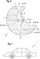
- Fig. 5 and 6 the wide embodiment of the electric machine 5 is shown.
- the stator 6, the housing 9 and the cooling circuit 10 of the electric machine 5 are in Fig. 5 and 6 not shown.
- radial recesses are incorporated as channels 11 ( Fig. 5 ).
- the channels 11 As a result, or form between the rotor 7 and the balance disk 15, the channels 11 ( Fig. 6 ).
- the electric machine 5 has two crescent-shaped radial throttle elements 31.
- At a nozzle 42 of the crescent-shaped Radialtross institute 31 each formed as a spring 35 elastic element 34 is arranged ( Fig. 5 ).
- the elastic element 34 and the spring 35 are in Fig. 6 not shown.
- the nozzle 42 with the spring 35 are arranged in a recess 43 of the balancing disk 15 (not shown).
- Fig. 6 the position of the radial throttle element 31 is shown at a very low speed. That's not in the Fig. 6 illustrated pump 27 flows through the gap 26, the channels 11 in the rotor shaft 16 and the channels 11 in the balancing disk 15 to the outlet openings 13 and injected onto the stator to be cooled 6 (not shown) and the rotor to be cooled 7 (not in Fig. 5 and 6 shown).
- the oil flows around as shown in Fig. 6 the radial throttle element 31.
- the radial throttle element 31 moves radially outward (not shown) due to the higher centrifugal force acting on the radial throttle element 31.
- the flow cross-sectional area of the channel 11 is reduced in the balancing disk 15 in the region of the radial throttle element 31, thereby reducing the flow rate of oil per unit time.
- the centrifugal force acting on the radial throttle element 31 counteracts the spring force of the spring 35.
- the radial throttle element 31 as means 14 for reducing the delivery rate of oil per unit time can also be designed so that from a certain speed of the rotating parts 12 no oil flows through the channels 11, ie that the flow cross-sectional area of the channels 11 zero or substantially equal Is zero.
Landscapes
- Engineering & Computer Science (AREA)
- Power Engineering (AREA)
- Motor Or Generator Cooling System (AREA)
- Connection Of Motors, Electrical Generators, Mechanical Devices, And The Like (AREA)
Applications Claiming Priority (2)
| Application Number | Priority Date | Filing Date | Title |
|---|---|---|---|
| DE102009001838A DE102009001838A1 (de) | 2009-03-25 | 2009-03-25 | Antriebseinrichtung |
| PCT/EP2010/052144 WO2010108736A2 (de) | 2009-03-25 | 2010-02-19 | Antriebseinrichtung |
Publications (2)
| Publication Number | Publication Date |
|---|---|
| EP2412083A2 EP2412083A2 (de) | 2012-02-01 |
| EP2412083B1 true EP2412083B1 (de) | 2017-04-12 |
Family
ID=42646334
Family Applications (1)
| Application Number | Title | Priority Date | Filing Date |
|---|---|---|---|
| EP10704829.0A Active EP2412083B1 (de) | 2009-03-25 | 2010-02-19 | Antriebseinrichtung |
Country Status (5)
| Country | Link |
|---|---|
| US (1) | US20120091833A1 (zh) |
| EP (1) | EP2412083B1 (zh) |
| CN (1) | CN102379078B (zh) |
| DE (1) | DE102009001838A1 (zh) |
| WO (1) | WO2010108736A2 (zh) |
Families Citing this family (17)
| Publication number | Priority date | Publication date | Assignee | Title |
|---|---|---|---|---|
| JP5060630B1 (ja) | 2011-03-31 | 2012-10-31 | 株式会社小松製作所 | 発電電動機の冷却構造及び発電電動機 |
| US20130133180A1 (en) * | 2011-11-29 | 2013-05-30 | Erik James John Neis | Electric vehicle motion generator |
| JP5714545B2 (ja) * | 2012-09-18 | 2015-05-07 | トヨタ自動車株式会社 | 電動機の冷却装置 |
| JP2014230393A (ja) * | 2013-05-22 | 2014-12-08 | トヨタ自動車株式会社 | 回転電機 |
| RU2680254C2 (ru) * | 2013-10-14 | 2019-02-19 | Анатолий Иванович Олефиренко | Способ изготовления постоянных магнитов |
| JP6396054B2 (ja) * | 2014-03-28 | 2018-09-26 | Ntn株式会社 | インホイールモータ駆動装置 |
| EP3154158B1 (en) * | 2015-10-09 | 2020-04-15 | AVL List GmbH | Hysteresis motor-brake |
| KR101846921B1 (ko) * | 2016-10-24 | 2018-04-09 | 현대자동차 주식회사 | 구동모터의 냉각유닛 |
| CN108044136B (zh) * | 2018-01-02 | 2024-05-14 | 中国计量大学 | 一种新型静压气浮电主轴 |
| DE102018222895A1 (de) | 2018-12-21 | 2020-06-25 | Em-Motive Gmbh | Antriebseinrichtung mit Fluidkühlung |
| DE102019122944A1 (de) * | 2019-08-27 | 2021-03-04 | Jheeco E-Drive Ag | Elektrische Maschine |
| DE102020207019A1 (de) | 2020-06-04 | 2021-12-09 | Volkswagen Aktiengesellschaft | Elektromotor für ein Kraftfahrzeug, Kraftfahrzeug sowie Verfahren zum Messen einer Temperatur eines Kühlmediums in einem Elektromotor |
| DE102020209709A1 (de) * | 2020-07-31 | 2022-02-03 | Seg Automotive Germany Gmbh | Elektrische Maschine |
| DE112021005172T5 (de) * | 2020-09-30 | 2023-08-10 | Valeo Eautomotive Germany Gmbh | Auslasseinheit für eine rotierende elektrische Maschine |
| DE102020212864A1 (de) | 2020-10-12 | 2022-04-14 | Volkswagen Aktiengesellschaft | Elektromaschine für ein Fahrzeug |
| JP7425023B2 (ja) | 2021-07-20 | 2024-01-30 | ダイハツ工業株式会社 | モータ |
| US11787551B1 (en) | 2022-10-06 | 2023-10-17 | Archer Aviation, Inc. | Vertical takeoff and landing aircraft electric engine configuration |
Family Cites Families (14)
| Publication number | Priority date | Publication date | Assignee | Title |
|---|---|---|---|---|
| DE2240797A1 (de) * | 1971-09-21 | 1973-03-29 | Westinghouse Electric Corp | Wassergekuehlter laeufer fuer elektrische maschinen, insbesondere turbogeneratoren |
| BE789008A (fr) * | 1971-09-21 | 1973-03-20 | Westinghouse Electric Corp | Rotor refroidi par liquide pour machines dynamoelectriques |
| BE789009A (fr) * | 1971-09-21 | 1973-03-20 | Westinghouse Electric Corp | Rotor refroidi par liquide pour machines dynamoelectriques |
| US5019733A (en) * | 1987-09-25 | 1991-05-28 | Honda Giken Kogyo Kabushiki Kaisha | AC generator |
| EP0811521B1 (en) * | 1995-12-21 | 2002-08-21 | Aisin Aw Co., Ltd. | Drive device for electric motorcars |
| JP4207242B2 (ja) * | 1998-04-28 | 2009-01-14 | 豊和工業株式会社 | 工作機械の主軸装置 |
| JP3559891B2 (ja) | 1998-06-22 | 2004-09-02 | 日産自動車株式会社 | 多層モータの冷却構造 |
| GB0101746D0 (en) * | 2001-01-23 | 2001-03-07 | Lucas Industries Ltd | Fluid distribution device |
| US7245050B2 (en) | 2001-08-20 | 2007-07-17 | Honda Giken Kogyo Kabushiki Kaisha | Internal combustion engine |
| JP3705193B2 (ja) * | 2001-12-03 | 2005-10-12 | 日産自動車株式会社 | ハイブリッド車両の駆動装置 |
| JP4096858B2 (ja) * | 2002-10-23 | 2008-06-04 | 日産自動車株式会社 | 車両用電動モータの冷却装置 |
| JP2006240429A (ja) | 2005-03-02 | 2006-09-14 | Toyota Motor Corp | 駆動ユニット |
| JP4747980B2 (ja) * | 2005-11-30 | 2011-08-17 | トヨタ自動車株式会社 | 回転電機 |
| JP4560067B2 (ja) * | 2007-07-19 | 2010-10-13 | トヨタ自動車株式会社 | 回転電機 |
-
2009
- 2009-03-25 DE DE102009001838A patent/DE102009001838A1/de not_active Withdrawn
-
2010
- 2010-02-19 WO PCT/EP2010/052144 patent/WO2010108736A2/de active Application Filing
- 2010-02-19 CN CN201080013333.8A patent/CN102379078B/zh active Active
- 2010-02-19 EP EP10704829.0A patent/EP2412083B1/de active Active
- 2010-02-19 US US13/260,412 patent/US20120091833A1/en not_active Abandoned
Non-Patent Citations (1)
| Title |
|---|
| None * |
Also Published As
| Publication number | Publication date |
|---|---|
| DE102009001838A1 (de) | 2010-09-30 |
| WO2010108736A2 (de) | 2010-09-30 |
| EP2412083A2 (de) | 2012-02-01 |
| US20120091833A1 (en) | 2012-04-19 |
| CN102379078A (zh) | 2012-03-14 |
| CN102379078B (zh) | 2016-01-06 |
| WO2010108736A3 (de) | 2012-01-19 |
Similar Documents
| Publication | Publication Date | Title |
|---|---|---|
| EP2412083B1 (de) | Antriebseinrichtung | |
| DE102012222188B4 (de) | Außeraxiale Hydraulikpumpenanordnung mit integrierter Ketten- und Kettenradanordnung | |
| DE112010003293B4 (de) | Antriebsvorrichtung für ein Fahrzeug | |
| DE102016216685A1 (de) | Rotor für eine elektrische Maschine | |
| DE102007054355A1 (de) | Verfahren und Vorrichtung zum Kühlen und Schmieren eines achsenversetzten Motors/Generators | |
| DE102012202460A1 (de) | Elektromotorische Getriebevorrichtung mit einstückigem Gehäuse | |
| WO2010102842A2 (de) | Elektromaschine | |
| DE112012000031T5 (de) | Kühlstruktur eines Generatormotors und Generatormotor | |
| EP2565422A2 (de) | Hilfsgerätegetriebeeinrichtung für ein Triebwerk | |
| DE112012000043T5 (de) | Generatormotor | |
| WO2012139820A2 (de) | Antriebsvorrichtung mit einer kühlbaren rotoranordnung | |
| DE102010001212A1 (de) | Kreiselpumpe | |
| EP2349768B1 (de) | Hybridantriebseinrichtung | |
| DE102010064061A1 (de) | Turboverdichter und Verfahren zur Verdichtung von Gas | |
| DE102012212423A1 (de) | Flüssigkeitspumpe | |
| DE102015218280A1 (de) | Lagerschmierung für elektrische Maschine | |
| EP4042545A1 (de) | Elektrische maschine mit integriertem kühlsystem | |
| WO2020239548A1 (de) | Elektrischer antrieb für ein fahrzeug in einem gehäuse | |
| WO2010145730A1 (de) | Laufzeug für eine fluidenergiemaschine sowie elektrisch angetriebener turbolader | |
| DE112019004906T5 (de) | Elektromotor für eine Achsbaugruppe | |
| EP1438510A2 (de) | Vakuumpumpe | |
| WO2023104480A1 (de) | Axialflussmaschine für ein kraftfahrzeug | |
| EP1233211B1 (de) | Ausgleichsgetriebe mit einer Schmiervorrichtung | |
| DE102012206139A1 (de) | Antriebsvorrichtung für einen Kraftwagen | |
| DE102016224898A1 (de) | Pumpeneinrichtung für ein Automatikgetriebe |
Legal Events
| Date | Code | Title | Description |
|---|---|---|---|
| PUAI | Public reference made under article 153(3) epc to a published international application that has entered the european phase |
Free format text: ORIGINAL CODE: 0009012 |
|
| AK | Designated contracting states |
Kind code of ref document: A2 Designated state(s): AT BE BG CH CY CZ DE DK EE ES FI FR GB GR HR HU IE IS IT LI LT LU LV MC MK MT NL NO PL PT RO SE SI SK SM TR |
|
| AX | Request for extension of the european patent |
Extension state: AL BA RS |
|
| R17D | Deferred search report published (corrected) |
Effective date: 20120119 |
|
| 17P | Request for examination filed |
Effective date: 20120719 |
|
| RBV | Designated contracting states (corrected) |
Designated state(s): AT BE BG CH CY CZ DE DK EE ES FI FR GB GR HR HU IE IS IT LI LT LU LV MC MK MT NL NO PL PT RO SE SI SK SM TR |
|
| DAX | Request for extension of the european patent (deleted) | ||
| 17Q | First examination report despatched |
Effective date: 20130614 |
|
| REG | Reference to a national code |
Ref country code: DE Ref legal event code: R079 Ref document number: 502010013454 Country of ref document: DE Free format text: PREVIOUS MAIN CLASS: H02K0009190000 Ipc: H02K0001320000 |
|
| GRAJ | Information related to disapproval of communication of intention to grant by the applicant or resumption of examination proceedings by the epo deleted |
Free format text: ORIGINAL CODE: EPIDOSDIGR1 |
|
| RIC1 | Information provided on ipc code assigned before grant |
Ipc: H02K 9/19 20060101ALI20161121BHEP Ipc: H02K 1/32 20060101AFI20161121BHEP |
|
| GRAP | Despatch of communication of intention to grant a patent |
Free format text: ORIGINAL CODE: EPIDOSNIGR1 |
|
| INTG | Intention to grant announced |
Effective date: 20170104 |
|
| GRAS | Grant fee paid |
Free format text: ORIGINAL CODE: EPIDOSNIGR3 |
|
| GRAA | (expected) grant |
Free format text: ORIGINAL CODE: 0009210 |
|
| AK | Designated contracting states |
Kind code of ref document: B1 Designated state(s): AT BE BG CH CY CZ DE DK EE ES FI FR GB GR HR HU IE IS IT LI LT LU LV MC MK MT NL NO PL PT RO SE SI SK SM TR |
|
| REG | Reference to a national code |
Ref country code: GB Ref legal event code: FG4D Free format text: NOT ENGLISH |
|
| REG | Reference to a national code |
Ref country code: CH Ref legal event code: EP |
|
| REG | Reference to a national code |
Ref country code: IE Ref legal event code: FG4D Free format text: LANGUAGE OF EP DOCUMENT: GERMAN |
|
| REG | Reference to a national code |
Ref country code: AT Ref legal event code: REF Ref document number: 884767 Country of ref document: AT Kind code of ref document: T Effective date: 20170515 |
|
| REG | Reference to a national code |
Ref country code: DE Ref legal event code: R096 Ref document number: 502010013454 Country of ref document: DE |
|
| REG | Reference to a national code |
Ref country code: NL Ref legal event code: MP Effective date: 20170412 |
|
| REG | Reference to a national code |
Ref country code: LT Ref legal event code: MG4D |
|
| PG25 | Lapsed in a contracting state [announced via postgrant information from national office to epo] |
Ref country code: NL Free format text: LAPSE BECAUSE OF FAILURE TO SUBMIT A TRANSLATION OF THE DESCRIPTION OR TO PAY THE FEE WITHIN THE PRESCRIBED TIME-LIMIT Effective date: 20170412 |
|
| PG25 | Lapsed in a contracting state [announced via postgrant information from national office to epo] |
Ref country code: NO Free format text: LAPSE BECAUSE OF FAILURE TO SUBMIT A TRANSLATION OF THE DESCRIPTION OR TO PAY THE FEE WITHIN THE PRESCRIBED TIME-LIMIT Effective date: 20170712 Ref country code: GR Free format text: LAPSE BECAUSE OF FAILURE TO SUBMIT A TRANSLATION OF THE DESCRIPTION OR TO PAY THE FEE WITHIN THE PRESCRIBED TIME-LIMIT Effective date: 20170713 Ref country code: HR Free format text: LAPSE BECAUSE OF FAILURE TO SUBMIT A TRANSLATION OF THE DESCRIPTION OR TO PAY THE FEE WITHIN THE PRESCRIBED TIME-LIMIT Effective date: 20170412 Ref country code: FI Free format text: LAPSE BECAUSE OF FAILURE TO SUBMIT A TRANSLATION OF THE DESCRIPTION OR TO PAY THE FEE WITHIN THE PRESCRIBED TIME-LIMIT Effective date: 20170412 Ref country code: LT Free format text: LAPSE BECAUSE OF FAILURE TO SUBMIT A TRANSLATION OF THE DESCRIPTION OR TO PAY THE FEE WITHIN THE PRESCRIBED TIME-LIMIT Effective date: 20170412 Ref country code: ES Free format text: LAPSE BECAUSE OF FAILURE TO SUBMIT A TRANSLATION OF THE DESCRIPTION OR TO PAY THE FEE WITHIN THE PRESCRIBED TIME-LIMIT Effective date: 20170412 |
|
| PG25 | Lapsed in a contracting state [announced via postgrant information from national office to epo] |
Ref country code: BG Free format text: LAPSE BECAUSE OF FAILURE TO SUBMIT A TRANSLATION OF THE DESCRIPTION OR TO PAY THE FEE WITHIN THE PRESCRIBED TIME-LIMIT Effective date: 20170712 Ref country code: PL Free format text: LAPSE BECAUSE OF FAILURE TO SUBMIT A TRANSLATION OF THE DESCRIPTION OR TO PAY THE FEE WITHIN THE PRESCRIBED TIME-LIMIT Effective date: 20170412 Ref country code: SE Free format text: LAPSE BECAUSE OF FAILURE TO SUBMIT A TRANSLATION OF THE DESCRIPTION OR TO PAY THE FEE WITHIN THE PRESCRIBED TIME-LIMIT Effective date: 20170412 Ref country code: LV Free format text: LAPSE BECAUSE OF FAILURE TO SUBMIT A TRANSLATION OF THE DESCRIPTION OR TO PAY THE FEE WITHIN THE PRESCRIBED TIME-LIMIT Effective date: 20170412 Ref country code: IS Free format text: LAPSE BECAUSE OF FAILURE TO SUBMIT A TRANSLATION OF THE DESCRIPTION OR TO PAY THE FEE WITHIN THE PRESCRIBED TIME-LIMIT Effective date: 20170812 |
|
| REG | Reference to a national code |
Ref country code: DE Ref legal event code: R097 Ref document number: 502010013454 Country of ref document: DE |
|
| PG25 | Lapsed in a contracting state [announced via postgrant information from national office to epo] |
Ref country code: EE Free format text: LAPSE BECAUSE OF FAILURE TO SUBMIT A TRANSLATION OF THE DESCRIPTION OR TO PAY THE FEE WITHIN THE PRESCRIBED TIME-LIMIT Effective date: 20170412 Ref country code: RO Free format text: LAPSE BECAUSE OF FAILURE TO SUBMIT A TRANSLATION OF THE DESCRIPTION OR TO PAY THE FEE WITHIN THE PRESCRIBED TIME-LIMIT Effective date: 20170412 Ref country code: CZ Free format text: LAPSE BECAUSE OF FAILURE TO SUBMIT A TRANSLATION OF THE DESCRIPTION OR TO PAY THE FEE WITHIN THE PRESCRIBED TIME-LIMIT Effective date: 20170412 Ref country code: DK Free format text: LAPSE BECAUSE OF FAILURE TO SUBMIT A TRANSLATION OF THE DESCRIPTION OR TO PAY THE FEE WITHIN THE PRESCRIBED TIME-LIMIT Effective date: 20170412 Ref country code: SK Free format text: LAPSE BECAUSE OF FAILURE TO SUBMIT A TRANSLATION OF THE DESCRIPTION OR TO PAY THE FEE WITHIN THE PRESCRIBED TIME-LIMIT Effective date: 20170412 |
|
| PLBE | No opposition filed within time limit |
Free format text: ORIGINAL CODE: 0009261 |
|
| STAA | Information on the status of an ep patent application or granted ep patent |
Free format text: STATUS: NO OPPOSITION FILED WITHIN TIME LIMIT |
|
| REG | Reference to a national code |
Ref country code: FR Ref legal event code: PLFP Year of fee payment: 9 |
|
| PG25 | Lapsed in a contracting state [announced via postgrant information from national office to epo] |
Ref country code: SM Free format text: LAPSE BECAUSE OF FAILURE TO SUBMIT A TRANSLATION OF THE DESCRIPTION OR TO PAY THE FEE WITHIN THE PRESCRIBED TIME-LIMIT Effective date: 20170412 |
|
| 26N | No opposition filed |
Effective date: 20180115 |
|
| PG25 | Lapsed in a contracting state [announced via postgrant information from national office to epo] |
Ref country code: SI Free format text: LAPSE BECAUSE OF FAILURE TO SUBMIT A TRANSLATION OF THE DESCRIPTION OR TO PAY THE FEE WITHIN THE PRESCRIBED TIME-LIMIT Effective date: 20170412 |
|
| REG | Reference to a national code |
Ref country code: CH Ref legal event code: PL |
|
| PG25 | Lapsed in a contracting state [announced via postgrant information from national office to epo] |
Ref country code: MC Free format text: LAPSE BECAUSE OF FAILURE TO SUBMIT A TRANSLATION OF THE DESCRIPTION OR TO PAY THE FEE WITHIN THE PRESCRIBED TIME-LIMIT Effective date: 20170412 Ref country code: MT Free format text: LAPSE BECAUSE OF FAILURE TO SUBMIT A TRANSLATION OF THE DESCRIPTION OR TO PAY THE FEE WITHIN THE PRESCRIBED TIME-LIMIT Effective date: 20170412 |
|
| GBPC | Gb: european patent ceased through non-payment of renewal fee |
Effective date: 20180219 |
|
| REG | Reference to a national code |
Ref country code: IE Ref legal event code: MM4A |
|
| REG | Reference to a national code |
Ref country code: BE Ref legal event code: MM Effective date: 20180228 |
|
| PG25 | Lapsed in a contracting state [announced via postgrant information from national office to epo] |
Ref country code: LU Free format text: LAPSE BECAUSE OF NON-PAYMENT OF DUE FEES Effective date: 20180219 Ref country code: CH Free format text: LAPSE BECAUSE OF NON-PAYMENT OF DUE FEES Effective date: 20180228 Ref country code: LI Free format text: LAPSE BECAUSE OF NON-PAYMENT OF DUE FEES Effective date: 20180228 |
|
| PG25 | Lapsed in a contracting state [announced via postgrant information from national office to epo] |
Ref country code: IE Free format text: LAPSE BECAUSE OF NON-PAYMENT OF DUE FEES Effective date: 20180219 |
|
| PG25 | Lapsed in a contracting state [announced via postgrant information from national office to epo] |
Ref country code: GB Free format text: LAPSE BECAUSE OF NON-PAYMENT OF DUE FEES Effective date: 20180219 Ref country code: BE Free format text: LAPSE BECAUSE OF NON-PAYMENT OF DUE FEES Effective date: 20180228 |
|
| REG | Reference to a national code |
Ref country code: AT Ref legal event code: MM01 Ref document number: 884767 Country of ref document: AT Kind code of ref document: T Effective date: 20180219 |
|
| PG25 | Lapsed in a contracting state [announced via postgrant information from national office to epo] |
Ref country code: AT Free format text: LAPSE BECAUSE OF NON-PAYMENT OF DUE FEES Effective date: 20180219 |
|
| PG25 | Lapsed in a contracting state [announced via postgrant information from national office to epo] |
Ref country code: TR Free format text: LAPSE BECAUSE OF FAILURE TO SUBMIT A TRANSLATION OF THE DESCRIPTION OR TO PAY THE FEE WITHIN THE PRESCRIBED TIME-LIMIT Effective date: 20170412 |
|
| PG25 | Lapsed in a contracting state [announced via postgrant information from national office to epo] |
Ref country code: HU Free format text: LAPSE BECAUSE OF FAILURE TO SUBMIT A TRANSLATION OF THE DESCRIPTION OR TO PAY THE FEE WITHIN THE PRESCRIBED TIME-LIMIT; INVALID AB INITIO Effective date: 20100219 Ref country code: PT Free format text: LAPSE BECAUSE OF FAILURE TO SUBMIT A TRANSLATION OF THE DESCRIPTION OR TO PAY THE FEE WITHIN THE PRESCRIBED TIME-LIMIT Effective date: 20170412 |
|
| PG25 | Lapsed in a contracting state [announced via postgrant information from national office to epo] |
Ref country code: MK Free format text: LAPSE BECAUSE OF NON-PAYMENT OF DUE FEES Effective date: 20170412 Ref country code: CY Free format text: LAPSE BECAUSE OF FAILURE TO SUBMIT A TRANSLATION OF THE DESCRIPTION OR TO PAY THE FEE WITHIN THE PRESCRIBED TIME-LIMIT Effective date: 20170412 |
|
| PGFP | Annual fee paid to national office [announced via postgrant information from national office to epo] |
Ref country code: FR Payment date: 20230217 Year of fee payment: 14 |
|
| PGFP | Annual fee paid to national office [announced via postgrant information from national office to epo] |
Ref country code: IT Payment date: 20230228 Year of fee payment: 14 |
|
| PGFP | Annual fee paid to national office [announced via postgrant information from national office to epo] |
Ref country code: DE Payment date: 20230426 Year of fee payment: 14 |