EP2408005A1 - Substrattransportverfahren - Google Patents
Substrattransportverfahren Download PDFInfo
- Publication number
- EP2408005A1 EP2408005A1 EP10750712A EP10750712A EP2408005A1 EP 2408005 A1 EP2408005 A1 EP 2408005A1 EP 10750712 A EP10750712 A EP 10750712A EP 10750712 A EP10750712 A EP 10750712A EP 2408005 A1 EP2408005 A1 EP 2408005A1
- Authority
- EP
- European Patent Office
- Prior art keywords
- substrate
- substrates
- substrate cassette
- retrieved
- transport
- Prior art date
- Legal status (The legal status is an assumption and is not a legal conclusion. Google has not performed a legal analysis and makes no representation as to the accuracy of the status listed.)
- Withdrawn
Links
Images


Classifications
-
- H10P72/3411—
-
- B—PERFORMING OPERATIONS; TRANSPORTING
- B65—CONVEYING; PACKING; STORING; HANDLING THIN OR FILAMENTARY MATERIAL
- B65G—TRANSPORT OR STORAGE DEVICES, e.g. CONVEYORS FOR LOADING OR TIPPING, SHOP CONVEYOR SYSTEMS OR PNEUMATIC TUBE CONVEYORS
- B65G49/00—Conveying systems characterised by their application for specified purposes not otherwise provided for
- B65G49/05—Conveying systems characterised by their application for specified purposes not otherwise provided for for fragile or damageable materials or articles
- B65G49/06—Conveying systems characterised by their application for specified purposes not otherwise provided for for fragile or damageable materials or articles for fragile sheets, e.g. glass
- B65G49/067—Sheet handling, means, e.g. manipulators, devices for turning or tilting sheet glass
-
- B—PERFORMING OPERATIONS; TRANSPORTING
- B65—CONVEYING; PACKING; STORING; HANDLING THIN OR FILAMENTARY MATERIAL
- B65G—TRANSPORT OR STORAGE DEVICES, e.g. CONVEYORS FOR LOADING OR TIPPING, SHOP CONVEYOR SYSTEMS OR PNEUMATIC TUBE CONVEYORS
- B65G49/00—Conveying systems characterised by their application for specified purposes not otherwise provided for
- B65G49/05—Conveying systems characterised by their application for specified purposes not otherwise provided for for fragile or damageable materials or articles
- B65G49/06—Conveying systems characterised by their application for specified purposes not otherwise provided for for fragile or damageable materials or articles for fragile sheets, e.g. glass
- B65G49/068—Stacking or destacking devices; Means for preventing damage to stacked sheets, e.g. spaces
-
- B—PERFORMING OPERATIONS; TRANSPORTING
- B65—CONVEYING; PACKING; STORING; HANDLING THIN OR FILAMENTARY MATERIAL
- B65G—TRANSPORT OR STORAGE DEVICES, e.g. CONVEYORS FOR LOADING OR TIPPING, SHOP CONVEYOR SYSTEMS OR PNEUMATIC TUBE CONVEYORS
- B65G2249/00—Aspects relating to conveying systems for the manufacture of fragile sheets
- B65G2249/02—Controlled or contamination-free environments or clean space conditions
Definitions
- the present invention relates to a substrate transport method including a heat treatment step in which a plurality of substrates loaded in multiple stages at predetermined vertical intervals are heat-treated in a processing chamber, a storing step in which the plurality of heat-treated substrates are retrieved one by one and sequentially stored in a substrate cassette capable of loading substrates in multiple stages, and a retrieving step in which the substrates are retrieved from the substrate cassette one by one, the substrates retrieved from the substrate cassette being transported to the following processing step.
- the present invention relates to a substrate transport method for transporting glass substrates, semiconductor substrates, liquid crystal substrates or the like.
- a front face electrode is formed on an insulated light-transmitting substrate such as a glass substrate.
- the front face electrode include a transparent conductive film formed by using tin oxide, zinc oxide, ITO or the like as a material.
- thermal CVD is favorably used, for example.
- a front face electrode separation line is formed. Note that this patterning step includes an alignment step for accurately patterning the front face electrode. In the front face electrode patterning step, patterning utilizing heating by laser irradiation (laser patterning) is favorably used.
- a photoelectric conversion layer is formed on the front face electrode, which has been subjected to patterning in the step (2).
- a material for the photoelectric conversion layer semiconductors made of Si, Ge, SiGe, SiC, SiN, GaAs, SiSn or the like can be used, for example.
- the semiconductor film of the photoelectric conversion layer has a three-layer structure including p-type, i-type and n-type. In this case, in the photoelectric conversion layer forming step, plasma CVD is favorably used, for example.
- this patterning step includes an alignment step for accurately patterning the photoelectric conversion layer.
- patterning utilizing heating by laser irradiation is favorably used.
- a rear face electrode is formed on the photoelectric conversion layer subjected to patterning in the step (4).
- the rear face electrode include a laminated film of a transparent conductive film formed by using a material such as tin oxide, zinc oxide, or ITO, and a metal film formed by using a material having good light reflectivity such as Ag, Al or Cr.
- a metal film formed by Ag is preferable due to its high reflectance.
- the sputtering method is favorably used, for example.
- this patterning step includes an alignment step for accurately patterning the rear face electrode.
- patterning utilizing heating by laser irradiation (laser patterning) is favorably used.
- a light-transmitting opening portion is formed by irradiating the fundamental wave of YAG laser, for example, from the glass surface onto the rear face electrode that has been subjected to patterning processing.
- etching is performed in order to remove residues caused by laser processing, and lastly, the rear face electrode side is sealed with an adhesion layer and a transparent sealing material, thereby forming a thin-film solar cell module.
- substrates are transported from the front face electrode forming step to the front face electrode patterning step, from the photoelectric conversion layer forming step to the photoelectric conversion layer patterning step, and from the rear face electrode forming step to the rear face electrode patterning step, respectively, by using a transport robot and a substrate cassette.
- FIG. 4 illustrates a schematic configuration of a substrate transport system for transporting substrates from the photoelectric conversion layer forming step to the photoelectric conversion layer patterning step, as an example.
- a plasma CVD apparatus 10 is used in the photoelectric conversion layer forming step.
- this substrate transport system includes the plasma CVD apparatus 10, a first transport robot 20 that retrieves a plurality of substrates (glass substrates) processed by the plasma CVD apparatus 10 one by one, and sequentially stores the substrates in a substrate cassette 30 that is capable of loading substrates in multiple stages, and a second transport robot 40 that retrieves the substrates from the substrate cassette 30 one by one, and transports the substrates to a pre-patterning alignment step 50.
- a substrate transport system that uses a substrate cassette to transport substrates from a plasma CVD apparatus to the following step is disclosed in Patent Document 1, for example.
- the plasma CVD apparatus 10 is a batch-type multiple-stage plasma CVD apparatus capable of loading substrates 1 in multiple stages at predetermined vertical intervals (although five stages are illustrated in this example, the number of stages is not limited to this) and processing the substrates at one time, and is configured by a deposition chamber 11 and a load lock chamber (retrieving chamber) 12.
- five pairs of supporting pieces 14a and 14b, each horizontally supporting the substrate 1 at the right and left ends thereof, are formed in five stages at predetermined vertical intervals, on side walls 13a and 13b on the right and left sides (the direction perpendicular to the paper in FIG. 4 ) of each of the chambers 11 and 12, so as to hold the substrates 1 (1a to 1b) respectively in five stages.
- the substrates 1 are transported from the deposition chamber 11 to the load lock chamber 12 with arms, not shown in the drawings, respectively holding the substrates 1, and moving the substrates 1 from the deposition chamber 11 to the load lock chamber 12 at one time.
- the substrate cassette 30 is also configured to be capable of loading the substrates 1 in multiple stages (five stages in this example) at predetermined vertical intervals, as shown in FIG. 5(b) . That is, in order to hold the substrates 1 in five stages, five pairs of supporting pieces 33a and 33b, each horizontally supporting the substrate 1 at the right and left ends thereof, are formed in five stages at predetermined vertical intervals, on side walls 32a and 32b on the right and left sides (the direction perpendicular to the paper plane) of a cassette main body 31 so as to hold the substrates 1 in five stages.
- the first transport robot 20 holds the substrates 1 with an robot arm one at a time, and transport the substrates 1 from the load lock chamber 12 to the substrate cassette 30.
- the second transport robot 40 also holds the substrates 1 with the robot arm one at a time, and transports the substrates 1 from the substrate cassette 30 to the alignment step.
- a conventional substrate transport method is performed as follows. Note that when each substrate 1 needs to be distinguished in the following description, a lower-case alphabetical letter is suffixed to the reference numeral 1 representing the substrate in order to distinguish the substrates 1. Also, in principle, in this description, the stages in the load lock chamber 12 and the substrate cassette 30 are counted from the bottom as the first stage, second stage, and the like. A conventional substrate transport method will be described below with reference to FIG. 4 .
- the first transport robot 20 retrieves the substrate 1a in the lowermost stage (the first stage) of the load lock chamber 12, and stores the substrate 1a in the uppermost stage (the fifth stage) of the substrate cassette 30.
- the first transport robot 20 retrieves the substrate 1b in the second stage of the load lock chamber 12, and stores the substrate 1b in the fourth stage (the second stage from the top) of the substrate cassette 30.
- the first transport robot 20 retrieves the substrate 1c in the third stage of the load lock chamber 12, and stores the substrate 1c in the third stage (the third stage from the top) of the substrate cassette 30.
- the substrates 1a to 1e are transported from the load lock chamber 12 to the substrate cassette 30 so as to invert the vertical order of the substrates. Accordingly, lastly, the first transport robot 20 retrieves the substrate 1e in the uppermost stage (the fifth stage) of the lock chamber 12, and stores the substrate 1e in the lowermost stage (the first stage) of the substrate cassette 30.
- the second transport robot 40 first retrieves the substrate 1e in the lowermost stage (the first stage) from the substrate cassette 30, and transports the substrate 1e to the alignment step 50.
- the second transport robot 40 retrieves the substrate 1d in the second stage of the substrate cassette 30, and transports the substrate 1d to the alignment step 50.
- the second transport robot 40 retrieves the substrate 1c in the third stage of the substrate cassette 30, and transports the substrate 1c to the alignment step 50.
- the substrates 1 are sequentially retrieved starting with the lowermost stage, and transported to the alignment step 50.
- the second transport robot 40 lastly retrieves the substrate 1a in the uppermost stage (the fifth stage) of the substrate cassette 30, and transports the substrate 1a to the alignment step 50.
- the first transport robot 20 and the second transport robot 40 both retrieve the substrates 1 starting with the lowermost stage. This is because if the substrates are retrieved starting with the uppermost stage, when a substrate 1 is retrieved, dust, dirt or the like may fall from a portion in contact with the substrate 1 onto substrates in lower stages. Accordingly, in order to prevent such falling of dust, dirt or the like onto substrates, substrates are always retrieved starting with the lowermost stage, and stored starting with the uppermost stage.
- the substrates 1 that have been processed in the deposition chamber 11 and transported to the load lock chamber 12 each wait to be retrieved from the load lock chamber 12, while the substrates 1 have absorbed heat.
- the temperature distribution in the load lock chamber 12 is such that hot air goes upward and air having a lower temperature goes downward due to air convection characteristics caused by heat.
- temperatures of the substrates 1a to 1e themselves that are waiting in the load lock chamber 12 become different, and the temperature difference is such that the temperature of the substrate 1a in the lowermost stage is low, and the temperature of the substrate 1e in the uppermost stage is the highest, the temperature of the substrates increasing towards the upper stages.
- the first transport robot 20 sequentially retrieves the substrates 1 starting with the substrate 1a at the bottom having a low temperature, and sequentially stores the substrates 1 starting with the uppermost stage of the substrate cassette 30.
- the second transport robot sequentially retrieves the substrates 1 starting with the substrate 1e at the bottom having a high temperature and transports the substrates 1 to the alignment step 50.
- the above operation can be understood as follows, if considered in terms of the transport time of the substrates 1. Note that it is assumed that the time required for the first transport robot 20 to retrieve one substrate from the load lock chamber 12 and store the substrate in the substrate cassette 30 is tx, and the time required for the second transport robot 40 to retrieve one substrate from the substrate cassette 30 and transport the substrate to the alignment step 50 is ty, and there is no waiting time for the transport between the robots.
- the substrate 1b in the second stage (the fourth stage from the top) of the load lock chamber 12 is retrieved second from the load lock chamber 12, and stored in the substrate cassette 30 in the transport time 1tx.
- the substrate 1c in the third stage (the third stage from the top) of the load lock chamber 12 is retrieved third from the load lock chamber 12, and stored in the substrate cassette 30 in the transport time 1tx.
- the substrate 1d in the fourth stage (the second stage from the top) of the load lock chamber 12 is retrieved fourth from the load lock chamber 12, and stored in the substrate cassette 30 in the transport time 1tx.
- a waiting time 1tx passes until the remaining one substrate 1e is stored in the substrate cassette 30.
- the total transport time for the substrate 1d to be retrieved from the load lock chamber 12 and transported to the alignment step 50 amounts to (2tx + 2ty).
- the substrate 1e in the uppermost stage of the load lock chamber 12 is retrieved fifth from the load lock chamber 12, and stored in the substrate cassette 30 in the transport time 1tx. In this case, there is no waiting time in the substrate cassette 30 for the substrate 1e, and thus the transport time of the substrate 1e from the load lock chamber 12 to the substrate cassette 30 is 1tx.
- the transport time from the substrate cassette 30 to the alignment step 50 since the substrate 1e is retrieved first from the substrate cassette 30, and it is retrieved from the substrate cassette 30 immediately after being stored therein to be transported to the alignment step 50. That is, no waiting time occurs to the substrate 1e in the substrate cassette 30.
- the transport time from the point in time when all the substrates 1a to 1e have been stored in the substrate cassette 30 until the substrate 1e is retrieved from the substrate cassette 30 and transported to the alignment step 50 amounts to 1ty.
- the total transport time for the substrate 1e to be retrieved from the load lock chamber 12 and transported to the alignment step 50 amounts to (1tx + 1ty).
- the total transport time (5tx + 5ty) of the substrate 1a retrieved from the lowermost stage of the load lock chamber 12 to the alignment step 50 and the total transport time (1tx + 1ty) of the substrate 1e retrieved from the uppermost stage of the load lock chamber 12 to the alignment step 50 constitutes a fivefold transport time difference.
- the substrate 1e is transported to the alignment step 50 at a high temperature before being fully cooled, and the substrate 1a is transported to the alignment step 50 at a low temperature after being fully cooled.
- This temperature difference is more conspicuous as the number of stages increases.
- the alignment step 50 adjustments for following patterning are performed. If there is a temperature difference between the substrates (glass substrates) 1a to 1e as described above, since the substrates themselves expands or contracts, alignment errors occur. As a result, at the time of laser patterning, a substrate that has not been fully cooled and has a high temperature is subjected to patterning in an expanded state, and a substrate that has been fully cooled and has a low temperature is subjected to patterning in a normal state, which causes an issue in that patterning errors occur, in other words, a large variance in products occurs.
- the present invention has been made in order to solve the above-described issues, and aims at providing a substrate transport method in which by eliminating (or reducing) a time difference in the substrate transport from the heat treatment step to the following processing step, a temperature difference between the substrates in the following alignment step and patterning step is eliminated, thereby preventing the occurrence of alignment errors and patterning errors due to expansion of the substrates.
- a substrate transport method of the present invention includes: a heat treatment step of performing heat treatment on a plurality of substrates loaded in multiple stages at predetermined vertical intervals in a processing chamber; a storing step of retrieving the plurality of heat-treated substrates one by one, and sequentially storing the substrates in a substrate cassette capable of loading substrates in multiple stages; and a retrieving step of retrieving the substrates from the substrate cassette one by one, the substrates retrieved from the substrate cassette being transported to a following processing step, wherein supporting pieces that support the substrates in a horizontal orientation are formed in the substrate cassette in a plurality of stages at predetermined vertical intervals, and partition plates are provided between the stages, and the substrates are transported from the substrate cassette to a following processing step by retrieving the substrates from the substrate cassette in an order in which the substrates have been retrieved from the processing chamber and stored in the substrate cassette, and transporting the substrates to the following processing step.
- a configuration may be adopted in which in the storing step, the substrates retrieved starting with the lowermost stage of the processing chamber (more specifically, the load lock chamber) are stored in the substrate cassette starting with the uppermost stage, and in the retrieving step, the substrates are sequentially retrieved starting with the uppermost stage of the substrate cassette and transported to the following processing step.
- the substrates are glass substrates
- the heat treatment step is a CVD processing step
- the following processing step is an alignment step
- the CVD processing step is a step of forming thin-film solar cell devices on the glass substrates
- the alignment step is an adjustment step for laser-patterning the thin-film solar cell devices formed on the glass substrates.
- the substrate transport method of the present invention also may use a substrate transport system as shown in FIG. 4 , including the plasma CVD apparatus 10, the first transport robot 20 that retrieves a plurality of substrates (glass substrates) processed by the plasma CVD apparatus 10 one by one, and sequentially stores the substrates in the substrate cassette 30 capable of loading substrates in multiple stages, and the second transport robot 40 that retrieves the substrates from the substrate cassette 30 one by one, and transports the substrates to the pre-patterning alignment step 50.
- the substrate transport system as shown in FIG. 4 , including the plasma CVD apparatus 10, the first transport robot 20 that retrieves a plurality of substrates (glass substrates) processed by the plasma CVD apparatus 10 one by one, and sequentially stores the substrates in the substrate cassette 30 capable of loading substrates in multiple stages, and the second transport robot 40 that retrieves the substrates from the substrate cassette 30 one by one, and transports the substrates to the pre-patterning alignment step 50.
- the transport method employed when transporting substrates from the substrate cassette 30 to the alignment step 50 is different from that in the conventional techniques.
- the substrates are sequentially retrieved starting with the uppermost stage of the substrate cassette 30 and transported to the following alignment step.
- the first-in first-out system is employed for the substrates stored in the substrate cassette 30.
- the total transport time for the substrate 1a stored in the lowermost stage of the load lock chamber 12 to be retrieved from the load lock chamber 12 and transported to the alignment step 50 is (5tx +1ty)
- the total transport time for the substrate 1e stored in the uppermost stage of the load lock chamber 12 to be retrieved from the load lock chamber 12 and transported to the alignment step 50 is (1tx + 5ty).
- the transport time tx is approximately the same as the transport time ty (e.g., tz)
- the total transportation time of the substrate 1a stored in the lowermost stage of the load lock chamber 12 and that of the substrate 1e stored in the uppermost stage of the load lock chamber 12 are approximately the same (6tz).
- their total transport times are between the total transport time of the substrate 1a and the total transport time of the substrate 1e, and thus with the substrate transport method of the present invention, the total transport times for all the substrates 1a to 1e can be made approximately the same.
- the substrates are retrieved from the substrate cassette 30 starting with the uppermost stage.
- FIG. 2 a configuration is adopted in which supporting pieces 33a and 33b horizontally supporting the substrates are formed on right and left side walls 32a and 32b inside a cassette main body 31 of the substrate cassette 30. Pairs of the supporting pieces 33a and 33b are formed in multiple stages at predetermined vertical intervals, and partition plates 34 are disposed between the stages each including a pair of supporting pieces 33a and 33b. In this manner, even when the substrates 1 are retrieved starting with the uppermost stage, dust or dirt caused when a substrate is retrieved falls onto the partition plate 34, and never falls onto substrates stored below.
- the present invention is configured as described above, and therefore it is possible to transport all substrates retrieved from the processing chamber in the heat treatment step to the following processing step in an approximately the same transport time. Therefore, it is possible that the substrates that have been transported to the following processing step are cooled to an approximately the same temperature. That is, an expansion difference between the substrates due to heat can be eliminated.
- the following processing step is an alignment step, for example, it is possible to eliminate alignment errors due to expansion of the substrates, which also enables to avoid the occurrence of variance in products in the following patterning step.
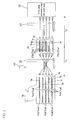
- FIG. 1 is a schematic configuration diagram of a substrate transport system to which a substrate transport method of the present invention is applied.
- the configuration of the substrate transport system is the same as that of the conventional substrate transport system described above and shown in FIG. 4 , and includes a plasma CVD apparatus 10, a first transport robot 20 that retrieves a plurality of substrates (glass substrates) processed by the plasma CVD apparatus 10 one by one, and sequentially stores the substrates in a substrate cassette 30 capable of loading substrates in multiple stages, and a second transport robot 40 that retrieves the substrates from the substrate cassette 30 one by one, and transports the substrates to a pre-patterning alignment step 50.
- a film thickness measurement apparatus 60 is disposed in a transport path between the plasma CVD apparatus 10 and the substrate cassette 30 for measuring the thickness of the film formed on the transported substrate.
- the film thickness measurement apparatus 60 measuring the thickness of the film formed on the substrate, if the measured value is less than or equal to a preset reference value, that substrate is eliminated from the manufacturing line as a defective product. In this manner, it is possible to prevent the occurrence of defective products due to defective film thickness.
- FIG. 2 illustrates the configuration of the substrate cassette 30 of the present invention.
- the substrate cassette 30 of the present invention has pairs of supporting pieces 33a and 33b horizontally supporting right and left ends of the substrates formed on right and left side walls 32a and 32b inside a cassette main body 31.
- the pairs of the supporting pieces 33a and 33b are formed in multiple stages at predetermined vertical intervals, and partition plates 34 are disposed between the stages, each stage including a pair of supporting pieces 33a and 33b. In this manner, even when the substrates 1 are retrieved starting with the uppermost stage, dust or dirt that has occurred while the substrate 1 is retrieved falls onto the partition plates 34, and never falls onto the substrates stored below.
- the substrate transport method of the present invention is performed as follows by using the substrate transport system configured as described above.
- the substrate transport method of the present invention will be described below with reference to FIG. 1 .
- the first transport robot 20 retrieves the substrate 1a in the lowermost stage (the first stage) of the load lock chamber 12, and stores the substrate 1a in the uppermost stage (the fifth stage) of the substrate cassette 30.
- the first transport robot 20 retrieves the substrate 1b in the second stage of the load lock chamber 12, and stores the substrate 1b in the fourth stage (the second stage from the top) of the substrate cassette 30.
- the first transport robot 20 retrieves the substrate 1c in the third stage of the load lock chamber 12, and stores the substrate 1c in the third stage (the third stage from the top) of the substrate cassette 30.
- the substrates 1a to 1e are transported from the load lock chamber 12 to the substrate cassette 30 so as to invert the vertical order of the substrates. Accordingly, lastly, the first transport robot 20 retrieves the substrate 1e in the uppermost stage (the fifth stage) of the lock chamber 12, and stores the substrate 1e in the lowermost stage (the first stage) of the substrate cassette 30.
- the second transport robot 40 first retrieves the substrate 1a in the uppermost stage (the fifth stage) from the substrate cassette 30, and transports the substrate 1a to the alignment step 50.
- the second transport robot 40 retrieves the substrate 1b in the fourth stage (the second stage from the top) of the substrate cassette 30, and transports the substrate 1d to the alignment step 50.
- the second transport robot 40 retrieves the substrate 1c in the third stage (the third stage from the top) of the substrate cassette 30, and transports the substrate 1c to the alignment step 50.
- the substrates 1 are sequentially retrieved starting with the uppermost stage, and transported to the alignment step 50.
- the second transport robot 40 retrieves lastly the substrate 1e in the lowermost stage (the first stage) of the substrate cassette 30, and transports the substrate 1e to the alignment step 50.
- the above substrate transport method is understood as follows, if considered in terms of the transport time of the substrates 1a to 1e. Note that it is assumed that the time required for the first transport robot 20 to retrieve one substrate from the load lock chamber 12 and store the substrate in the substrate cassette 30 is tx, and the time required for the second transport robot 40 to retrieve one substrate from the substrate cassette 30 and transport the substrate to the alignment step 50 is ty, there is no waiting time for the transport between the robots.
- the transport time from the substrate cassette 30 to the alignment step 50 since the substrate 1a is retrieved first from the substrate cassette 30, it is retrieved from the substrate cassette 30 immediately after being stored therein to be transported to the alignment step 50. That is, no waiting time occurs to the substrate 1a in the substrate cassette 30. Accordingly, the transport time from the point in time when all the substrates 1a to 1h have been stored in the substrate cassette 30 until the substrate 1a is retrieved from the substrate cassette 30 and transported to the alignment step 50 is 1ty. As a result, the total transport time for the substrate 1a to be retrieved from the load lock chamber 12 and transported to the alignment step 50 amounts to (5tx + 1ty).
- the total transport time for the substrate 1b to be retrieved from the load lock chamber 12 and transported to the alignment step 50 amounts to (4tx + 2ty).
- the substrate 1c in the third stage from the bottom of the load lock chamber 12 is retrieved third from the load lock chamber 12, and stored in the substrate cassette 30 in the transport time 1tx.
- the total transport time for the substrate 1c to be retrieved from the load lock chamber 12 and transported to the alignment step 50 amounts to (3tx + 3ty).
- the total transport time for the substrate 1d to be retrieved from the load lock chamber 12 and transported to the alignment step 50 amounts to (2tx + 4ty).
- the substrate 1e in the uppermost stage of the load lock chamber 12 is retrieved fifth from the load lock chamber 12, and stored in the substrate cassette 30 in the transport time 1tx. In this case, no waiting time occurs to the substrate 1e, and thus the transport time from the point in time when the substrate 1d has been retrieved from the load lock chamber 12 until all the substrates 1a to 1e are stored in the substrate cassette 30 is 1tx.
- the transport time from the substrate cassette 30 to the alignment step 50 since the substrate 1e is retrieved fifth from the substrate cassette 30, a waiting time 4ty for the preceding four substrates 1a to 1d to be retrieved and transported to the alignment step 50 occurs.
- the total transport time for the substrate 1e to be retrieved from the load lock chamber 12 and transported to the alignment step 50 amounts to (1tx + 5ty).
- the total transport time (5tx + 1ty) of the substrate 1a retrieved from the lowermost stage of the load lock chamber 12 to the alignment step 50 and the total transport time (1tx + 5ty) of the substrate 1e retrieved from the uppermost stage of the load lock chamber 12 to the alignment step 50 has a transport time difference that is four times the difference between time tx and time ty (
- the total transport time of the substrate 1a retrieved from the lowermost stage of the load lock chamber 12 to the alignment step 50 and the total transport time of the substrate 1e retrieved from the uppermost stage of the load lock chamber 12 to the alignment step 50 are both 3tz.
- their total transport times are between the total transport time of the substrate 1a and the total transport time of the substrate 1e, and thus with the substrate transport method of the present invention, the total transport times for all the substrates 1a to 1e can be made approximately the same, namely, 3tz.
- pairs of the supporting pieces 33a and 33b are formed on the right and left side walls 32a and 32b inside the cassette main body 31 as supporting structures for horizontally supporting the substrates inside the substrate cassette 30, but the structure for supporting the substrate is not limited to these.
- projection portions 33c that function as supporting pieces may be provided.
- several projection portions 33c are formed at predetermined intervals in the width direction and the depth direction (the depth direction is not shown in the drawing), and substrates are horizontally supported by these projection portions 33c.
- the substrates 1 retrieved from the load lock chamber 12 are stored in the substrate cassette 30 starting with the uppermost stage, and when the substrates 1 are retrieved from the substrate cassette 30, they are retrieved starting with the uppermost stage.
- the partition plates 34 are provided in the substrate cassette 30, the substrates 1 retrieved from the load lock chamber 12 may be stored in the substrate cassette 30 starting with the lowermost stage, and when the substrates 1 are retrieved from the substrate cassette 30, they may be retrieved starting with the lowermost stage, for example.
- the stage from which to start storage is not limited to the uppermost stage or the lowermost stage, and the substrate 1 retrieved from the load lock chamber 12 may be stored in an arbitrary empty stage in the substrate cassette 30. In this case, the order in which the substrates 1 are stored is remembered, and the substrates 1 may be retrieved in that order.
- the substrate transport method of the present invention is described by using a case in which the substrate transport method of the present invention is applied to the transport method of glass substrates for solar cells, but the present invention is not limited to the transport method of glass substrates for solar cells.
- the substrate transport method of the present invention can be applied to the transport method of semiconductor substrates or liquid crystal substrates in a manufacturing line for semiconductor devices or liquid crystal panels.
- the substrate transport method of the present invention is preferably used for a substrate transport method in a manufacturing line for solar cells, a substrate transport method in a manufacturing line for semiconductor devices, and a substrate transport method in a manufacturing line for liquid crystal panels, for example.
Landscapes
- Container, Conveyance, Adherence, Positioning, Of Wafer (AREA)
- Photovoltaic Devices (AREA)
Applications Claiming Priority (2)
| Application Number | Priority Date | Filing Date | Title |
|---|---|---|---|
| JP2009055066 | 2009-03-09 | ||
| PCT/JP2010/053313 WO2010103958A1 (ja) | 2009-03-09 | 2010-03-02 | 基板搬送方法 |
Publications (1)
| Publication Number | Publication Date |
|---|---|
| EP2408005A1 true EP2408005A1 (de) | 2012-01-18 |
Family
ID=42728248
Family Applications (1)
| Application Number | Title | Priority Date | Filing Date |
|---|---|---|---|
| EP10750712A Withdrawn EP2408005A1 (de) | 2009-03-09 | 2010-03-02 | Substrattransportverfahren |
Country Status (4)
| Country | Link |
|---|---|
| US (1) | US8313974B2 (de) |
| EP (1) | EP2408005A1 (de) |
| JP (1) | JP5236067B2 (de) |
| WO (1) | WO2010103958A1 (de) |
Cited By (1)
| Publication number | Priority date | Publication date | Assignee | Title |
|---|---|---|---|---|
| CN110053973A (zh) * | 2019-05-05 | 2019-07-26 | 东旭(昆山)显示材料有限公司 | 用于玻璃上下料的方法和用于玻璃上下料的装置 |
Families Citing this family (2)
| Publication number | Priority date | Publication date | Assignee | Title |
|---|---|---|---|---|
| JP5665647B2 (ja) * | 2011-05-09 | 2015-02-04 | 富士機械製造株式会社 | 部品供給装置 |
| JP7221403B2 (ja) * | 2019-09-05 | 2023-02-13 | 株式会社Kokusai Electric | 基板処理装置、半導体装置の製造方法およびプログラム |
Family Cites Families (11)
| Publication number | Priority date | Publication date | Assignee | Title |
|---|---|---|---|---|
| JPH02121346A (ja) | 1988-10-28 | 1990-05-09 | Dainippon Screen Mfg Co Ltd | 基板処理装置 |
| JP3139155B2 (ja) | 1992-07-29 | 2001-02-26 | 東京エレクトロン株式会社 | 真空処理装置 |
| US5636960A (en) | 1992-07-29 | 1997-06-10 | Tokyo Electron Limited | Apparatus for detecting and aligning a substrate |
| US5558482A (en) | 1992-07-29 | 1996-09-24 | Tokyo Electron Limited | Multi-chamber system |
| JPH07297258A (ja) | 1994-04-26 | 1995-11-10 | Tokyo Electron Ltd | 板状体の搬送装置 |
| JP3632812B2 (ja) | 1997-10-24 | 2005-03-23 | シャープ株式会社 | 基板搬送移載装置 |
| JPH11260889A (ja) | 1998-03-13 | 1999-09-24 | Ebara Corp | イオン注入装置 |
| US6313469B1 (en) | 1998-03-13 | 2001-11-06 | Ebara Corporation | Substrate handling apparatus and ion implantation apparatus |
| JP2005235916A (ja) | 2004-02-18 | 2005-09-02 | Mitsubishi Heavy Ind Ltd | 薄膜太陽電池製造システム |
| JP4646532B2 (ja) | 2004-03-10 | 2011-03-09 | シャープ株式会社 | 薄膜のパターニング方法およびパターニング装置、ならびに薄膜太陽電池の製造方法 |
| JP4544361B2 (ja) | 2008-11-26 | 2010-09-15 | 日亜化学工業株式会社 | 発光装置 |
-
2010
- 2010-03-02 US US13/254,606 patent/US8313974B2/en not_active Expired - Fee Related
- 2010-03-02 WO PCT/JP2010/053313 patent/WO2010103958A1/ja not_active Ceased
- 2010-03-02 EP EP10750712A patent/EP2408005A1/de not_active Withdrawn
- 2010-03-02 JP JP2011503777A patent/JP5236067B2/ja not_active Expired - Fee Related
Non-Patent Citations (1)
| Title |
|---|
| See references of WO2010103958A1 * |
Cited By (1)
| Publication number | Priority date | Publication date | Assignee | Title |
|---|---|---|---|---|
| CN110053973A (zh) * | 2019-05-05 | 2019-07-26 | 东旭(昆山)显示材料有限公司 | 用于玻璃上下料的方法和用于玻璃上下料的装置 |
Also Published As
| Publication number | Publication date |
|---|---|
| JPWO2010103958A1 (ja) | 2012-09-13 |
| WO2010103958A1 (ja) | 2010-09-16 |
| US20110318867A1 (en) | 2011-12-29 |
| JP5236067B2 (ja) | 2013-07-17 |
| US8313974B2 (en) | 2012-11-20 |
Similar Documents
| Publication | Publication Date | Title |
|---|---|---|
| US20070281090A1 (en) | System architecture and method for solar panel formation | |
| CN110106480B (zh) | 用于溅射系统的玻璃托盘 | |
| US20110313565A1 (en) | Substrate Processing Apparatus And Method For Loading And Unloading Substrates | |
| US10199250B2 (en) | Substrate processing device | |
| US10651073B2 (en) | Sample transfer system and solar cell production method | |
| KR101992074B1 (ko) | 성막 장치 및 성막 방법 그리고 태양 전지의 제조 방법 | |
| US8313974B2 (en) | Substrate transport method | |
| JP4691131B2 (ja) | スパッタ成膜方法、電子素子の製造方法、スパッタ装置 | |
| US8647912B2 (en) | Solar cell and method for manufacturing solar cell | |
| JP5731838B2 (ja) | トレイ式基板搬送システム、成膜方法及び電子装置の製造方法 | |
| JP2014515875A (ja) | マルチチャンバー太陽電池モジュール処理システム及び方法 | |
| KR101446631B1 (ko) | 대면적기판용 플라즈마 처리 장치 | |
| JP2018040029A (ja) | 成膜装置及び成膜方法並びに太陽電池の製造方法 | |
| CN111893462B (zh) | 用于cvd设备的方法及相应的cvd设备 | |
| US20110203655A1 (en) | Photovoltaic device protection layer | |
| JP2012015457A (ja) | 薄膜太陽電池製造装置、薄膜太陽電池の製造方法および薄膜太陽電池 | |
| US9543457B2 (en) | Method and system for manufacturing back contacts of photovoltaic devices | |
| US20110039421A1 (en) | Heat treatment method | |
| JP6075611B2 (ja) | 成膜装置 | |
| JP2012019044A (ja) | 薄膜太陽電池製造装置、薄膜太陽電池の製造方法、およびそれを用いて製造された薄膜太陽電池 | |
| CN211079409U (zh) | 一种用于连续式生产的晶体硅太阳能电池扩散炉及生产线 | |
| JP2014056874A (ja) | 太陽電池の製造方法および太陽電池の製造装置 | |
| JP2008021824A (ja) | ボートトレイ及びウェーハ用熱処理炉 | |
| WO2025260379A1 (zh) | 镀膜装置 | |
| KR102035300B1 (ko) | 기판 처리 장치 |
Legal Events
| Date | Code | Title | Description |
|---|---|---|---|
| PUAI | Public reference made under article 153(3) epc to a published international application that has entered the european phase |
Free format text: ORIGINAL CODE: 0009012 |
|
| 17P | Request for examination filed |
Effective date: 20110818 |
|
| AK | Designated contracting states |
Kind code of ref document: A1 Designated state(s): AT BE BG CH CY CZ DE DK EE ES FI FR GB GR HR HU IE IS IT LI LT LU LV MC MK MT NL NO PL PT RO SE SI SK SM TR |
|
| DAX | Request for extension of the european patent (deleted) | ||
| STAA | Information on the status of an ep patent application or granted ep patent |
Free format text: STATUS: THE APPLICATION HAS BEEN WITHDRAWN |
|
| 18W | Application withdrawn |
Effective date: 20130801 |