EP2407752A2 - Messvorrichtung - Google Patents
Messvorrichtung Download PDFInfo
- Publication number
- EP2407752A2 EP2407752A2 EP11169688A EP11169688A EP2407752A2 EP 2407752 A2 EP2407752 A2 EP 2407752A2 EP 11169688 A EP11169688 A EP 11169688A EP 11169688 A EP11169688 A EP 11169688A EP 2407752 A2 EP2407752 A2 EP 2407752A2
- Authority
- EP
- European Patent Office
- Prior art keywords
- light
- distance measuring
- pulsed distance
- light emitting
- photodetector
- Prior art date
- Legal status (The legal status is an assumption and is not a legal conclusion. Google has not performed a legal analysis and makes no representation as to the accuracy of the status listed.)
- Granted
Links
Images

Classifications
-
- G—PHYSICS
- G01—MEASURING; TESTING
- G01S—RADIO DIRECTION-FINDING; RADIO NAVIGATION; DETERMINING DISTANCE OR VELOCITY BY USE OF RADIO WAVES; LOCATING OR PRESENCE-DETECTING BY USE OF THE REFLECTION OR RERADIATION OF RADIO WAVES; ANALOGOUS ARRANGEMENTS USING OTHER WAVES
- G01S17/00—Systems using the reflection or reradiation of electromagnetic waves other than radio waves, e.g. lidar systems
- G01S17/88—Lidar systems specially adapted for specific applications
- G01S17/89—Lidar systems specially adapted for specific applications for mapping or imaging
-
- G—PHYSICS
- G01—MEASURING; TESTING
- G01C—MEASURING DISTANCES, LEVELS OR BEARINGS; SURVEYING; NAVIGATION; GYROSCOPIC INSTRUMENTS; PHOTOGRAMMETRY OR VIDEOGRAMMETRY
- G01C15/00—Surveying instruments or accessories not provided for in groups G01C1/00 - G01C13/00
- G01C15/002—Active optical surveying means
-
- G—PHYSICS
- G01—MEASURING; TESTING
- G01C—MEASURING DISTANCES, LEVELS OR BEARINGS; SURVEYING; NAVIGATION; GYROSCOPIC INSTRUMENTS; PHOTOGRAMMETRY OR VIDEOGRAMMETRY
- G01C3/00—Measuring distances in line of sight; Optical rangefinders
- G01C3/02—Details
- G01C3/06—Use of electric means to obtain final indication
- G01C3/08—Use of electric radiation detectors
-
- G—PHYSICS
- G01—MEASURING; TESTING
- G01S—RADIO DIRECTION-FINDING; RADIO NAVIGATION; DETERMINING DISTANCE OR VELOCITY BY USE OF RADIO WAVES; LOCATING OR PRESENCE-DETECTING BY USE OF THE REFLECTION OR RERADIATION OF RADIO WAVES; ANALOGOUS ARRANGEMENTS USING OTHER WAVES
- G01S17/00—Systems using the reflection or reradiation of electromagnetic waves other than radio waves, e.g. lidar systems
- G01S17/02—Systems using the reflection of electromagnetic waves other than radio waves
- G01S17/06—Systems determining position data of a target
- G01S17/08—Systems determining position data of a target for measuring distance only
- G01S17/10—Systems determining position data of a target for measuring distance only using transmission of interrupted, pulse-modulated waves
- G01S17/14—Systems determining position data of a target for measuring distance only using transmission of interrupted, pulse-modulated waves wherein a voltage or current pulse is initiated and terminated in accordance with the pulse transmission and echo reception respectively, e.g. using counters
-
- G—PHYSICS
- G01—MEASURING; TESTING
- G01S—RADIO DIRECTION-FINDING; RADIO NAVIGATION; DETERMINING DISTANCE OR VELOCITY BY USE OF RADIO WAVES; LOCATING OR PRESENCE-DETECTING BY USE OF THE REFLECTION OR RERADIATION OF RADIO WAVES; ANALOGOUS ARRANGEMENTS USING OTHER WAVES
- G01S17/00—Systems using the reflection or reradiation of electromagnetic waves other than radio waves, e.g. lidar systems
- G01S17/02—Systems using the reflection of electromagnetic waves other than radio waves
- G01S17/06—Systems determining position data of a target
- G01S17/42—Simultaneous measurement of distance and other co-ordinates
-
- G—PHYSICS
- G01—MEASURING; TESTING
- G01S—RADIO DIRECTION-FINDING; RADIO NAVIGATION; DETERMINING DISTANCE OR VELOCITY BY USE OF RADIO WAVES; LOCATING OR PRESENCE-DETECTING BY USE OF THE REFLECTION OR RERADIATION OF RADIO WAVES; ANALOGOUS ARRANGEMENTS USING OTHER WAVES
- G01S7/00—Details of systems according to groups G01S13/00, G01S15/00, G01S17/00
- G01S7/48—Details of systems according to groups G01S13/00, G01S15/00, G01S17/00 of systems according to group G01S17/00
- G01S7/481—Constructional features, e.g. arrangements of optical elements
- G01S7/4811—Constructional features, e.g. arrangements of optical elements common to transmitter and receiver
- G01S7/4812—Constructional features, e.g. arrangements of optical elements common to transmitter and receiver transmitted and received beams following a coaxial path
-
- G—PHYSICS
- G01—MEASURING; TESTING
- G01S—RADIO DIRECTION-FINDING; RADIO NAVIGATION; DETERMINING DISTANCE OR VELOCITY BY USE OF RADIO WAVES; LOCATING OR PRESENCE-DETECTING BY USE OF THE REFLECTION OR RERADIATION OF RADIO WAVES; ANALOGOUS ARRANGEMENTS USING OTHER WAVES
- G01S7/00—Details of systems according to groups G01S13/00, G01S15/00, G01S17/00
- G01S7/48—Details of systems according to groups G01S13/00, G01S15/00, G01S17/00 of systems according to group G01S17/00
- G01S7/481—Constructional features, e.g. arrangements of optical elements
- G01S7/4814—Constructional features, e.g. arrangements of optical elements of transmitters alone
- G01S7/4815—Constructional features, e.g. arrangements of optical elements of transmitters alone using multiple transmitters
Definitions
- the present invention relates to a measuring device for measuring a multiple number of points on an object to be measured at the same time and for acquiring point group data.
- JP-A-2008-76303 discloses a laser scanner, which comprises a deflection mirror to be rotated in elevation (high-low) direction around a horizontal axis and to be rotated in horizontal direction around vertical axis, and a projecting light optical system having an optical axis concurring with the vertical axis and for projecting a pulsed distance measuring light along the optical axis.
- the pulsed distance measuring light emitted from the projecting light optical system is projected reciprocally for scanning at predetermined angles to each other in elevation direction by using the deflection mirror. Then, by rotating the deflection mirror, the pulsed distance measuring light is projected in total circumferential direction, or, a reflected light of the pulsed distance measuring light is received, and distance is measured for each of the pulsed distance measuring lights, and point group data in total circumferential direction is acquired.
- the laser scanner as described above is installed on a mobile object such as an automobile together with an image pickup device. By acquiring images and the point group data while moving, images with three-dimensional data is obtained.
- the laser scanner as described above may be costly, and a measuring device, which is lower-priced and can acquire the point group data in simpler manner is desired.
- the present invention provides a measuring device, comprising a light source unit for projecting a pulsed distance measuring light toward an object to be measured, a projecting light optical system for projecting the pulsed distance measuring light emitted from the light source unit on the object to be measured, a light receiving optical system for receiving a reflected pulsed distance measuring light from the object to be measured, a light receiving part having a single photodetector for detecting the reflected pulsed distance measuring light as received, and a control unit for measuring a distance by measuring time from light emission of the pulsed distance measuring light to receipt of the reflected pulsed distance measuring light based on a detection signal from the photodetector, wherein the light source unit has a plurality of light emitting sources arranged in a known relation with respect to an optical axis of the projecting light optical system, and a driving unit for driving the light emitting sources at a predetermined time interval, the light receiving part has a reduced optical system arranged at position conjugate to the light emitting source and used for
- the invention provides the measuring device as described above, wherein the light emitting sources are arranged along a line with a predetermined distance from each other. Further, the invention provides the measuring device as described above, wherein the light receiving part comprises a plurality of light receiving optical fibers for receiving the reflected pulsed distance measuring lights and a aggregate light optical fiber for binding the reflected pulsed distance measuring lights from the plurality of light receiving optical fibers in one bundle and for guiding the reflected pulsed distance measuring lights to the photodetector, and wherein the light receiving optical fibers are so arranged that incident end surfaces of the light receiving optical fibers is disposed at positions conjugate to each of the light emitting sources.
- the invention provides a measuring device as described above, wherein the control unit has a resonator and an arithmetic unit, wherein the resonator outputs an attenuation waveform in time series for each of the photodetection signals from the photodetector and the arithmetic unit calculates a distance for each of the pulsed distance measuring lights based on time difference between time point when a first 0 level of the attenuation waveform is detected and the timing when the driving unit emits the light emitting sources.
- the invention provides the measuring device as described above, for acquiring point group data, wherein the measuring device is installed on a mobile object, the light emitting sources are arranged in a direction perpendicular to advancing direction of the mobile object, the light emitting sources issue the pulsed distance measuring lights during processes when the mobile object is moved.
- the present invention provides a measuring device, comprising a light source unit for projecting a pulsed distance measuring light toward an object to be measured, a projecting light optical system for projecting the pulsed distance measuring light emitted from the light source unit on the object to be measured, a light receiving optical system for receiving a reflected pulsed distance measuring light from the object to be measured, a light receiving part having a single photodetector for detecting the reflected pulsed distance measuring light as received, and a control unit for measuring a distance by measuring time from light emission of the pulsed distance measuring light to receipt of the reflected pulsed distance measuring light based on a detection signal from the photodetector, wherein the light source unit has a plurality of light emitting sources arranged in a known relation with respect to an optical axis of the projecting light optical system, and a driving unit for driving the light emitting sources at a predetermined time interval, the light receiving part has a reduced optical system arranged at position conjugate to the light emitting source and used for guiding the reflected
- the invention provides a measuring device as described above, wherein the light emitting sources are arranged along a line with a predetermined distance from each other. As a result, it is possible to measure a distance almost at the same time without projecting the pulsed distance measuring lights for scanning to different points.
- the invention provides the measuring device as described above, wherein the light receiving part comprises a plurality of light receiving optical fibers for receiving the reflected pulsed distance measuring lights and a aggregate light optical fiber for binding the reflected pulsed distance measuring lights from the plurality of light receiving optical fibers in one bundle and for guiding the reflected pulsed distance measuring lights to the photodetector, and wherein the light receiving optical fibers are so arranged that incident end surfaces of the light receiving optical fibers is disposed at positions conjugate to each of the light emitting sources.
- the photodetecting optical fibers selectively receives the reflected pulsed distance measuring lights from the corresponding light emitting sources, noise lights are low, and distance measurement can be carried out with high accuracy.
- the invention provides the measuring device as described above, wherein the control unit has a resonator and an arithmetic unit, wherein the resonator outputs an attenuation waveform in time series for each of the photodetection signals from the photodetector and the arithmetic unit calculates a distance for each of the pulsed distance measuring lights based on time difference between time point when a first 0 level of the attenuation waveform is detected and the timing when the driving unit emits the light emitting sources.
- the control unit has a resonator and an arithmetic unit, wherein the resonator outputs an attenuation waveform in time series for each of the photodetection signals from the photodetector and the arithmetic unit calculates a distance for each of the pulsed distance measuring lights based on time difference between time point when a first 0 level of the attenuation waveform is detected and the timing when the driving unit emits the light emitting sources.
- the invention provides the measuring device as described above, for acquiring point group data, wherein the measuring device is installed on a mobile object, the light emitting sources are arranged in a direction perpendicular to advancing direction of the mobile object, the light emitting sources issue the pulsed distance measuring lights during processes when the mobile object is moved.
- the measuring device may not have functions for scanning on the pulsed distance measuring lights, it is possible to acquire point group data for wider range.
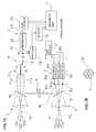
- reference numeral 2 represents a light source unit
- numeral 3 represents a projecting light optical system
- numeral 4 represents a light receiving optical system
- numeral 5 represents an internal reference light optical system
- numeral 6 represents a light receiving part
- numeral 7 represents a control unit.
- the light source unit 2 has a plurality of pulsed laser diodes (hereinafter referred as "PLD") 8a, 8b, 8c, Vietnamese as light emitting sources, and driving units 9a, 9b and 9c, each of which is a means for emitting the PLD respectively.
- PLDs 8a, 8b, 8c, Vietnamese are arranged along a line with a predetermined distance from each other in vertical direction.
- Each of the PLDs 8a, 8b, 8c, Vietnamese is driven respectively by the driving units 9a, 9b, 9c, Across to emit the pulsed beams.
- Each of the pulse laser beams emitted from the PLDs 8a, 8b, 8c, Vietnamese is projected to an object to be measured (not shown) via the projecting light optical system 3 as pulsed distance measuring lights 10.
- Each of the PLDs 8a, 8b, 8c, Vietnamese is located at a known position with respect to the projecting light optical system 3. Therefore, each of elevation angles ⁇ a, ⁇ b, ⁇ c, Vietnamese of the pulsed distance measuring lights 10a, 10b, 10c, Vietnamese as emitted from the PLDs 8a, 8b, 8c, Across are already known.
- the light receiving part 6 has as many light receiving optical fibers 11a, 11b, 11c, Vietnamese as the PLDs 8a, 8b, 8c, Vietnamese, and a single photodetecting element 12, e.g. a photodiode (PD), serving as a photodetector.
- a photodetecting element 12 e.g. a photodiode (PD), serving as a photodetector.
- Each of the light receiving optical fibers 11a, 11b, 11c, Vietnamese has an incident end surface respectively.
- the incident end surface is disposed at a predetermined distance from each other in vertical direction, and each being set at a position conjugate with light-emitting surface of the PLDs 8a, 8b, 8c, etc. respectively.
- the light receiving optical fibers 11a, 11b, 11c, Vietnamese are bundled together in a single aggregate light optical fiber 13, and an exit end surface of the aggregate light optical fiber 13 is located face-to-face to the photodetecting element 12.
- the aggregate light optical fiber 13 may not be designed as the bundled light receiving optical fibers 11a, 11b, 11c, Vietnamese, and may be designed as a single optical fiber where a reflected pulsed distance measuring light 10' from each of the light receiving optical fibers 11a, 11b, 11c, Vietnamese enters respectively.
- the light receiving optical fibers 11a, 11b, 11c, Vietnamese and the aggregate light optical fiber 13 receive all of the reflected pulsed distance measuring lights 10' and make up together a single reduced optical system for guiding the light to the single photodetecting element 12.
- the reduced optical system may be an optical member having incident end surface where all of the reflected pulsed distance measuring lights 10' can enter instead of the plurality of light receiving optical fibers.
- the reflected pulsed distance measuring lights 10' as reflected from the objects to be measured enter the light receiving part 6 via the light receiving optical system 4. These entered reflected pulsed distance measuring lights 10' enter the light receiving optical fibers 11a, 11b, 11c, Vietnamese to match the PLDs 8a, 8b, 8c, Vietnamese for each pulse and are guided to the photodetecting element 12 respectively via the light receiving optical fibers 11a, 11b, 11c, Vietnamese and are detected by the photodetecting element 12.
- the internal reference light optical system 5 has a first half-mirror 14 and a second half-mirror 15. Then, each of a part of the pulsed distance measuring lights 10a, 10b, 10c, Vietnamese as emitted from the PLDs 8a, 8b, 8c, Vietnamese is split and is guided toward the light receiving optical fibers 11a, 11b, 11c, Vietnamese as an internal reference light 16.
- the control unit 7 has an arithmetic unit 17, an oscillator 18, a counter 19, a timing generator 21, a resonator 22, and a signal processor 23.
- a clock signal issued from the oscillator 18 is inputted to the timing generator 21, the counter 19, and the signal processor 23.
- the timing generator 21 determines light emission timing of the PLDs 8a, 8b, 8c, Vietnamese based on the clock signal from the oscillator 18, and issues a timing signal to the driving units 9a, 9b, 9c, .
- the driving units 9a, 9b, 9c, Vietnamese divides the PLDs 8a, 8b, 8c, Vietnamese based on the timing signal by time division at a predetermined time interval and emits light. This time interval is set to longer than the time of the pulsed distance measuring lights 10 to reach and come back from the object to be measured both ways.
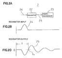
- a photodetection signal 24 is issued, and the photodetection signal 24 is inputted to the resonator 22 (see Fig. 2 (A) and Fig. 2 (B) ).
- the resonator 22 forms an attenuation waveform 25 and outputs the attenuation waveform 25 to the signal processor 23 (see Fig. 2 (C) ).
- the signal processor 23 detects a time point To where the attenuation waveform 25 is first turned to 0, and a detection signal is sent to the arithmetic unit 17.
- the internal reference light 16 passing through the internal reference light optical system 5 enters the photodetecting element 12, and the photodetection signal 24 of the internal reference light 16 is inputted to the resonator 22.
- the attenuation waveform 25 is outputted from the resonator 22, and the detection signal at a time point Ti when 0 level is detected by the signal processor 23 is outputted to the arithmetic unit 17.
- a light-emitting timing signal is inputted via the counter 19.
- a time interval from the light emission of the PLD 8 to the time point when T 0 and Ti are detected and time difference ⁇ T, i.e. (T 0 - Ti) is calculated. Based on the value of ⁇ T, a distance to the object to be measured is determined.
- each of the distances is measured.
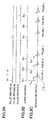
- Fig. 3 shows conditions of light emission of the PLDs 8a, 8b, 8c, Vietnamese and conditions of the output from the resonator 22 when the reflected pulsed distance measuring lights 10' are received.
- a case where the PLDs are three, i.e., the PLDs 8a, 8b, and 8c is shown. Because the operation to detect the reflected pulsed distance measuring lights 10' are the same as the operation to detect the internal reference light 16, description will be given on a case where the reflected pulsed distance measuring lights 10' are detected.
- the driving units 9a, 9b and 9c make the PLDs 8a, 8b and 8c to emit sequentially at a predetermined time interval I from each other (see Fig. 3 (A) and Fig. 3 (B) ).
- the pulsed distance measuring lights 10, which are projected respectively from the PLDs 8a, 8b and 8c, are projected to the object to be measured via the projecting light optical system 3, and are reflected by the object to be measured. After being reflected by the object to be measured, the reflected pulsed distance measuring lights 10' enter the light receiving part 6 via the light receiving optical system 4.
- the PLDs 8a, 8b and 8c are located at positions conjugate to incident ends of the light receiving optical fibers 11a, 11b and 11c. Therefore, the pulsed distance measuring light 10a from the PLD 8a enters the light receiving optical fiber 11a, and the pulsed distance measuring lights 10b and 10c from the PLD 8b and the PLD 8c enter the light receiving optical fibers 11b and 11c respectively under such conditions that the pulsed distance measuring lights include delay times according to each measuring distance.
- the reflected pulsed distance measuring lights 10' selectively enter the light receiving optical fibers 11a, 11b and 11c respectively, and the entering of the noise lights of the light receiving optical fibers 11a, 11b and 11c is suppressed respectively.
- the light receiving optical fibers 11a, 11b and 11c are bundled together, and the reflected pulsed distance measuring lights 10a', 10b' and 10c' are guided to the photodetecting element 12 as the single aggregate light optical fiber 13. Because the pulsed distance measuring lights 10a, 10b and 10c are emitted at the time interval I, the reflected pulsed distance measuring lights 10a', 10b' and 10c' detected by the photodetecting element 12 also has the time interval I as described above.
- the time interval I is set according to the difference of the distances to be measured.
- the signal outputted from the photodetecting element 12 and the attenuation waveform 25 outputted from the resonator 22 are the signals arranged in time series.
- the light emission timing of the driving units 9a, 9b and 9c i.e. the timing signals Ta, Tb and Tc
- the attenuation waveform 25 outputted from the resonator 22 is generated at the moment when a time to and from the object to be measured has elapsed according to the timing signals Ta, Tb and Tc, respectively.
- a distance to the object to be measured can be determined by external light based on the time difference of the timing signals Ta, Tb and Tc.
- a distance of the internal optical path can be measured, and by subtracting this distance of the internal optical path, the distance to the object to be measured can be precisely determined.
- the pulsed distance measuring lights 10a, 10b and 10c (the reflected pulsed distance measuring lights 10a', 10b' and 10c') emitted from a plurality of the PLDs 8a, 8b and 8c are detected by the single photodetecting element 12. Further, the reflected pulsed distance measuring lights 10a' 10b' and 10c' can be identified, and distance measurement of a plurality of points can be determined almost at the same time on the object to be measured.
- the PLDs 8a, 8b, 8c, Vietnamese and the light receiving optical fibers 11a, 11b, 11c, Vietnamese are arranged in the vertical direction, while these may be arranged in horizontal direction. Further, if these are arranged in a known relation with respect to the optical axis, these may be arranged in form of matrix or in form of multiple concentricity. In short, depending on the aspect of the measurement, the arrangement may be selected so that the optimal point group can be obtained.
- the measuring device By installing the measuring device according to the present embodiment on a mobile object such as automobile, and by performing the measurement while the mobile object is moving, it is possible to acquire point group data, which has a width in vertical direction and is extended in form of a band in horizontal direction. Therefore, no complicated mechanism to scan the distance measuring light is needed. Further, by a plurality of the PLDs 8, it is possible to determine measuring points located at positions different from each other at the same time. Also, only one photodetecting element would suffice as the light receiving part 6, and it is possible to acquire the point group data in easier manner.
- a GPS and an azimuth finder to detect the projecting direction of the pulsed distance measuring light 10 are installed on the mobile object, and if a position of the mobile object in the ground coordinate system is measured, three-dimensional data in an absolute coordinate of the object to be measured can be acquired.
- the measuring device 1 is installed on a ceiling of a mobile object 27, which is a vehicle, and measurement is made on an earthen filling 28.
- the measuring device 1 has an image pickup device, acquires point group data, and also can acquire a moving picture.
- a GPS position measuring device (not shown) and an azimuth finder (not shown) for detecting the projecting direction of the pulsed distance measuring light 10 are installed on the mobile object 27 so that a position of the mobile object 27, i.e. a position of the measuring device 1 on the ground coordinate system, is measured.
- the measurement is carried out by moving the mobile object 27 around the earthen filling 28.
- the measuring device 1 By the measuring device 1, the moving picture of the earthen filling 28 can be picked up, and distance measurement can be performed by the measuring device 1.
- the measuring device 1 From the measuring device 1, a plurality of the pulsed distance measuring lights 10 aligned along a line in vertical direction with a predetermined distance from each other are projected with pulses. By these pulsed distance measuring lights 10, a distance is measured by each light and by each pulse.
- the mobile object 27 is moving while the pulsed distance measuring lights 10 aligned along the line are projected. Therefore, the measurement range has a width in vertical direction and is in form of a band extended in horizontal direction, and it is possible to acquire the point group data in band-like form.
- images can be obtained at the predetermined time interval.
- a position of image pickup and a position where the point group data have been acquired are measured based on the position coordinates acquired by GPS.
- images are associated with the point group data, and image data with three-dimensional data can be acquired.
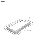
- Fig. 5 shows distance measuring points determined with respect to the earthen filling 28 as a multiple number of point groups.
- Reference numeral 29 denotes a running locus of the mobile object 27 measured in the present embodiment.
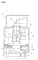
- Fig. 6 shows an example of the measuring device 1, to which the present invention is applied.
- the same components as shown in Fig. 1 are referred by the same symbol, and detailed description is not given here.
- the measuring device 1 primarily comprises a leveling unit 31, a rotary mechanism 32 mounted on the leveling unit 31, a measuring device main unit 33 rotatably supported on the rotary mechanism 32, and a measuring light projecting unit 34 installed on an upper portion of the measuring device main unit 33.
- the leveling unit 31 has a pivot pin 35 for tiltably supporting the rotary mechanism 32 in any direction as desired and also has two adjusting screws 36 mounted respectively on two apexes of a triangle with another apex on the pivot pin 35.
- a leveling motor 37 When the adjusting screw 36 is rotated by means of a leveling motor 37, leveling of the measuring device 1 can be carried out.
- a lower end 38 of the measuring device main unit 33 is inserted into an interior portion of the rotary mechanism 32.
- a horizontal rotary gear 39 is installed on the lower end.
- a driving gear 41 is engaged with the horizontal rotary gear 39, and the driving gear 41 is rotated by a horizontal rotary motor 42.
- On the lower end 38 a horizontal angle detector 43 is mounted, and by this horizontal angle detector 43, direction of the measuring device main unit 33 is detected.
- the measuring device main unit 33 has a lens barrel 44, which is installed concentrically with rotation axis of the measuring device main unit 33, and a projecting light optical system 3 and a light receiving optical system 4 are accommodated in the lens barrel 44 (see Fig. 1 ).
- Optical axis of each of the projecting light optical system 3 and the light receiving optical system 4 concurs with the rotation axis respectively.
- an image photodetector 45 is provided as an image pickup device. Also, a light source unit 2 and a light receiving part 6 are integrally mounted on a side of the lens barrel 44.
- a deflection mirror 46 which is a component element of the projecting light optical system 3 and the light receiving optical axis 4, is installed at an angle of 45° with respect to the rotation axis.
- the pulsed distance measuring lights 10 emitted from the light source unit 2 are projected by being deflected in horizontal direction.
- a reflected pulsed distance measuring light 10' from the object to be measured is deflected and directed to enter the light receiving part 6.
- the pulsed distance measuring lights 10 aligned in vertical direction are emitted at a predetermined time interval from the light source unit 2. From the deflection mirror 46, the pulsed distance measuring lights 10 aligned in a predetermined elevation angle in vertical direction are projected.
- the reflected pulsed distance measuring lights 10' reflected from the object to be measured enter the deflection mirror 46, are deflected by the deflection mirror 46 and enter the light receiving part 6. Based on the result of photodetection by the light receiving part 6, a distance is measured.
- the measuring device main unit 33 is rotated by the horizontal rotary motor 42, and point group data in total circumferential direction can be acquired.
- the rotary mechanism 32 may omitted. In this case, because the measuring device 1 has no movable part, and the structure of the measuring device 1 is extremely simple.
- the deflection mirror 46 can be rotated in vertical direction, the measuring range in vertical direction can be extended, and the point group data can be acquired in wider range.
- the pulsed distance measuring lights 10 are emitted from a plurality of PLDs 8.
- the point group with high density can be acquired without increasing the light emission duty ratio.
Landscapes
- Physics & Mathematics (AREA)
- Engineering & Computer Science (AREA)
- General Physics & Mathematics (AREA)
- Radar, Positioning & Navigation (AREA)
- Remote Sensing (AREA)
- Electromagnetism (AREA)
- Computer Networks & Wireless Communication (AREA)
- Optical Radar Systems And Details Thereof (AREA)
- Measurement Of Optical Distance (AREA)
Applications Claiming Priority (1)
| Application Number | Priority Date | Filing Date | Title |
|---|---|---|---|
| JP2010162010A JP5912234B2 (ja) | 2010-07-16 | 2010-07-16 | 測定装置 |
Publications (3)
| Publication Number | Publication Date |
|---|---|
| EP2407752A2 true EP2407752A2 (de) | 2012-01-18 |
| EP2407752A3 EP2407752A3 (de) | 2016-09-21 |
| EP2407752B1 EP2407752B1 (de) | 2023-09-06 |
Family
ID=45466733
Family Applications (1)
| Application Number | Title | Priority Date | Filing Date |
|---|---|---|---|
| EP11169688.6A Active EP2407752B1 (de) | 2010-07-16 | 2011-06-13 | Messvorrichtung |
Country Status (3)
| Country | Link |
|---|---|
| US (1) | US8638449B2 (de) |
| EP (1) | EP2407752B1 (de) |
| JP (1) | JP5912234B2 (de) |
Cited By (2)
| Publication number | Priority date | Publication date | Assignee | Title |
|---|---|---|---|---|
| US10386175B2 (en) | 2012-05-18 | 2019-08-20 | Acergy France SAS | Pipe measurement |
| CN114355373A (zh) * | 2022-03-14 | 2022-04-15 | 成都量芯集成科技有限公司 | 一种激光测距装置 |
Families Citing this family (16)
| Publication number | Priority date | Publication date | Assignee | Title |
|---|---|---|---|---|
| JP5653715B2 (ja) | 2010-10-27 | 2015-01-14 | 株式会社トプコン | レーザ測量機 |
| US8836922B1 (en) * | 2013-08-20 | 2014-09-16 | Google Inc. | Devices and methods for a rotating LIDAR platform with a shared transmit/receive path |
| JP6347674B2 (ja) | 2014-06-04 | 2018-06-27 | 株式会社トプコン | レーザスキャナシステム |
| JP6671629B2 (ja) * | 2015-03-18 | 2020-03-25 | 株式会社リコー | 物体検出装置、センシング装置、及び移動体装置 |
| JP6539501B2 (ja) * | 2015-05-28 | 2019-07-03 | 株式会社トプコン | 測量装置 |
| JP6788396B2 (ja) * | 2016-07-05 | 2020-11-25 | 株式会社トプコン | 光波距離計 |
| JP6773503B2 (ja) * | 2016-09-27 | 2020-10-21 | 株式会社トプコン | レーザスキャナシステム及び点群データのレジストレーション方法 |
| DE102017114565A1 (de) | 2017-06-29 | 2019-01-03 | Osram Opto Semiconductors Gmbh | Optische Abstandsmessvorrichtung und Verfahren zum Betreiben einer optischen Abstandsmessvorrichtung |
| JP6953233B2 (ja) * | 2017-08-24 | 2021-10-27 | 株式会社トプコン | 3次元測量装置 |
| JP7117092B2 (ja) * | 2017-09-25 | 2022-08-12 | 株式会社トプコン | レーザ測定方法及びレーザ測定装置 |
| JP7016709B2 (ja) * | 2018-01-30 | 2022-02-07 | ソニーセミコンダクタソリューションズ株式会社 | 測距モジュール、測距方法、及び、電子機器 |
| JP7135350B2 (ja) * | 2018-03-13 | 2022-09-13 | 株式会社リコー | 物体検出装置、移動体装置及び物体検出方法 |
| EP3767336B1 (de) * | 2018-03-16 | 2023-03-08 | NEC Corporation | Lichtüberwachungsvorrichtung und -verfahren |
| CN115327555A (zh) * | 2021-05-10 | 2022-11-11 | 信泰光学(深圳)有限公司 | 光学装置 |
| GB2614872B (en) * | 2021-11-26 | 2024-09-18 | Guidance Automation Ltd | Navigation module |
| CN120254875B (zh) * | 2025-05-29 | 2025-09-19 | 浙江科聪控制技术有限公司 | 一种基于反射标识物的二维激光全局定位算法 |
Citations (1)
| Publication number | Priority date | Publication date | Assignee | Title |
|---|---|---|---|---|
| JP2008076303A (ja) | 2006-09-22 | 2008-04-03 | Topcon Corp | 位置測定装置及び位置測定方法及び位置測定プログラム |
Family Cites Families (27)
| Publication number | Priority date | Publication date | Assignee | Title |
|---|---|---|---|---|
| FR2615279B1 (fr) * | 1987-05-11 | 1990-11-02 | Commissariat Energie Atomique | Capteur de deplacement a fibres optiques decalees |
| JP3155331B2 (ja) * | 1992-04-21 | 2001-04-09 | オリンパス光学工業株式会社 | 距離測定装置 |
| US5455669A (en) | 1992-12-08 | 1995-10-03 | Erwin Sick Gmbh Optik-Elektronik | Laser range finding apparatus |
| JP3151581B2 (ja) * | 1992-12-21 | 2001-04-03 | 株式会社トプコン | 光波距離計 |
| JP3120202B2 (ja) * | 1993-11-18 | 2000-12-25 | 株式会社トプコン | パルス方式の光波距離計 |
| JPH07159538A (ja) * | 1993-12-07 | 1995-06-23 | Copal Co Ltd | 光照射式測距装置 |
| JPH07218632A (ja) * | 1994-02-01 | 1995-08-18 | Nikon Corp | 距離測定装置 |
| JPH0954157A (ja) * | 1995-08-14 | 1997-02-25 | Topcon Corp | 距離測定装置 |
| US5988862A (en) | 1996-04-24 | 1999-11-23 | Cyra Technologies, Inc. | Integrated system for quickly and accurately imaging and modeling three dimensional objects |
| EP1081459B1 (de) | 1999-08-31 | 2002-06-19 | Leica Geosystems AG | Tachymeter-Fernrohr |
| JP4491661B2 (ja) * | 1999-11-17 | 2010-06-30 | 株式会社トプコン | 光波距離計 |
| JP4486737B2 (ja) | 2000-07-14 | 2010-06-23 | アジア航測株式会社 | モービルマッピング用空間情報生成装置 |
| JP4758568B2 (ja) * | 2001-06-18 | 2011-08-31 | 大成建設株式会社 | トンネル形状の三次元測定装置及び三次元測定方法 |
| JP3911575B2 (ja) * | 2001-12-18 | 2007-05-09 | 株式会社トプコン | パルス方式の光波距離計 |
| US6759979B2 (en) | 2002-01-22 | 2004-07-06 | E-Businesscontrols Corp. | GPS-enhanced system and method for automatically capturing and co-registering virtual models of a site |
| JP3937154B2 (ja) | 2002-06-28 | 2007-06-27 | 株式会社トプコン | 位置検出装置 |
| JP4247371B2 (ja) | 2002-07-05 | 2009-04-02 | 財団法人生産技術研究奨励会 | 三次元データ取得装置 |
| CN100578525C (zh) | 2002-07-10 | 2010-01-06 | 哈曼贝克自动系统股份有限公司 | 生成物体三维电子模型的系统和方法 |
| JP2004163292A (ja) | 2002-11-13 | 2004-06-10 | Topcon Corp | 測量装置と電子的記憶媒体 |
| JP2004317237A (ja) | 2003-04-15 | 2004-11-11 | Topcon Corp | 測量装置 |
| JP2004361315A (ja) | 2003-06-06 | 2004-12-24 | Nissan Motor Co Ltd | レーダ装置 |
| JP4102324B2 (ja) | 2004-03-29 | 2008-06-18 | 株式会社トプコン | 測量データ処理システム、測量データ処理プログラム及び電子地図表示装置 |
| JP2006010506A (ja) * | 2004-06-25 | 2006-01-12 | Sharp Corp | 光学式測距センサおよび自走式掃除機 |
| JP4878127B2 (ja) * | 2005-06-10 | 2012-02-15 | 株式会社トプコン | 時間差測定装置および距離測定装置並びに距離測定方法 |
| JPWO2008099939A1 (ja) | 2007-02-13 | 2010-05-27 | 株式会社ニコン・トリンブル | 光分割素子、距離測定装置 |
| JP2009236774A (ja) * | 2008-03-27 | 2009-10-15 | Hokuyo Automatic Co | 三次元測距装置 |
| JP5653715B2 (ja) | 2010-10-27 | 2015-01-14 | 株式会社トプコン | レーザ測量機 |
-
2010
- 2010-07-16 JP JP2010162010A patent/JP5912234B2/ja not_active Expired - Fee Related
-
2011
- 2011-06-13 US US13/158,800 patent/US8638449B2/en active Active
- 2011-06-13 EP EP11169688.6A patent/EP2407752B1/de active Active
Patent Citations (1)
| Publication number | Priority date | Publication date | Assignee | Title |
|---|---|---|---|---|
| JP2008076303A (ja) | 2006-09-22 | 2008-04-03 | Topcon Corp | 位置測定装置及び位置測定方法及び位置測定プログラム |
Cited By (2)
| Publication number | Priority date | Publication date | Assignee | Title |
|---|---|---|---|---|
| US10386175B2 (en) | 2012-05-18 | 2019-08-20 | Acergy France SAS | Pipe measurement |
| CN114355373A (zh) * | 2022-03-14 | 2022-04-15 | 成都量芯集成科技有限公司 | 一种激光测距装置 |
Also Published As
| Publication number | Publication date |
|---|---|
| JP5912234B2 (ja) | 2016-04-27 |
| JP2012021949A (ja) | 2012-02-02 |
| US8638449B2 (en) | 2014-01-28 |
| EP2407752A3 (de) | 2016-09-21 |
| US20120013917A1 (en) | 2012-01-19 |
| EP2407752B1 (de) | 2023-09-06 |
Similar Documents
| Publication | Publication Date | Title |
|---|---|---|
| EP2407752B1 (de) | Messvorrichtung | |
| EP2447666B1 (de) | Lasermessinstrument | |
| JP7242849B2 (ja) | 再帰反射体のマッピングのための方法およびシステム | |
| US11402506B2 (en) | Laser measuring method and laser measuring instrument | |
| EP2972471B1 (de) | Lidar-scanner | |
| US6879384B2 (en) | Process and apparatus for measuring an object space | |
| EP2381272B1 (de) | Laserscanner | |
| EP2952929B1 (de) | Laserscannersystem | |
| GB2437384A (en) | Multiple fanned laser beam metrology system | |
| US11531104B2 (en) | Full waveform multi-pulse optical rangefinder instrument | |
| US20210124021A1 (en) | Laser scanner | |
| US20180292514A1 (en) | Laser Scanner | |
| US20220155456A1 (en) | Systems and Methods for Real-Time LIDAR Range Calibration | |
| US10267659B2 (en) | Angle detecting device and surveying instrument | |
| CN108205141B (zh) | 用于运行激光测距仪的方法 | |
| EP3696499B1 (de) | Vermessungssystem mit einem rotierenden spiegel | |
| US20240118421A1 (en) | Scanning measuring device with fiber network | |
| EP3709052A1 (de) | Objektdetektor | |
| JP2023127741A (ja) | 測量装置 | |
| JP6749191B2 (ja) | スキャナ装置および測量装置 | |
| JP2025006183A (ja) | 測量装置 |
Legal Events
| Date | Code | Title | Description |
|---|---|---|---|
| 17P | Request for examination filed |
Effective date: 20110613 |
|
| AK | Designated contracting states |
Kind code of ref document: A2 Designated state(s): AL AT BE BG CH CY CZ DE DK EE ES FI FR GB GR HR HU IE IS IT LI LT LU LV MC MK MT NL NO PL PT RO RS SE SI SK SM TR |
|
| AX | Request for extension of the european patent |
Extension state: BA ME |
|
| PUAI | Public reference made under article 153(3) epc to a published international application that has entered the european phase |
Free format text: ORIGINAL CODE: 0009012 |
|
| PUAL | Search report despatched |
Free format text: ORIGINAL CODE: 0009013 |
|
| AK | Designated contracting states |
Kind code of ref document: A3 Designated state(s): AL AT BE BG CH CY CZ DE DK EE ES FI FR GB GR HR HU IE IS IT LI LT LU LV MC MK MT NL NO PL PT RO RS SE SI SK SM TR |
|
| AX | Request for extension of the european patent |
Extension state: BA ME |
|
| RIC1 | Information provided on ipc code assigned before grant |
Ipc: G01C 15/00 20060101AFI20160816BHEP |
|
| RBV | Designated contracting states (corrected) |
Designated state(s): AL AT BE BG CH CY CZ DE DK EE ES FI FR GB GR HR HU IE IS IT LI LT LU LV MC MK MT NL NO PL PT RO RS SE SI SK SM TR |
|
| STAA | Information on the status of an ep patent application or granted ep patent |
Free format text: STATUS: EXAMINATION IS IN PROGRESS |
|
| 17Q | First examination report despatched |
Effective date: 20200131 |
|
| GRAP | Despatch of communication of intention to grant a patent |
Free format text: ORIGINAL CODE: EPIDOSNIGR1 |
|
| STAA | Information on the status of an ep patent application or granted ep patent |
Free format text: STATUS: GRANT OF PATENT IS INTENDED |
|
| INTG | Intention to grant announced |
Effective date: 20230327 |
|
| GRAS | Grant fee paid |
Free format text: ORIGINAL CODE: EPIDOSNIGR3 |
|
| GRAA | (expected) grant |
Free format text: ORIGINAL CODE: 0009210 |
|
| STAA | Information on the status of an ep patent application or granted ep patent |
Free format text: STATUS: THE PATENT HAS BEEN GRANTED |
|
| AK | Designated contracting states |
Kind code of ref document: B1 Designated state(s): AL AT BE BG CH CY CZ DE DK EE ES FI FR GB GR HR HU IE IS IT LI LT LU LV MC MK MT NL NO PL PT RO RS SE SI SK SM TR |
|
| REG | Reference to a national code |
Ref country code: GB Ref legal event code: FG4D |
|
| REG | Reference to a national code |
Ref country code: CH Ref legal event code: EP |
|
| REG | Reference to a national code |
Ref country code: DE Ref legal event code: R096 Ref document number: 602011074225 Country of ref document: DE |
|
| REG | Reference to a national code |
Ref country code: IE Ref legal event code: FG4D |
|
| REG | Reference to a national code |
Ref country code: LT Ref legal event code: MG9D |
|
| REG | Reference to a national code |
Ref country code: NL Ref legal event code: MP Effective date: 20230906 |
|
| PG25 | Lapsed in a contracting state [announced via postgrant information from national office to epo] |
Ref country code: GR Free format text: LAPSE BECAUSE OF FAILURE TO SUBMIT A TRANSLATION OF THE DESCRIPTION OR TO PAY THE FEE WITHIN THE PRESCRIBED TIME-LIMIT Effective date: 20231207 |
|
| PG25 | Lapsed in a contracting state [announced via postgrant information from national office to epo] |
Ref country code: SE Free format text: LAPSE BECAUSE OF FAILURE TO SUBMIT A TRANSLATION OF THE DESCRIPTION OR TO PAY THE FEE WITHIN THE PRESCRIBED TIME-LIMIT Effective date: 20230906 Ref country code: RS Free format text: LAPSE BECAUSE OF FAILURE TO SUBMIT A TRANSLATION OF THE DESCRIPTION OR TO PAY THE FEE WITHIN THE PRESCRIBED TIME-LIMIT Effective date: 20230906 Ref country code: NO Free format text: LAPSE BECAUSE OF FAILURE TO SUBMIT A TRANSLATION OF THE DESCRIPTION OR TO PAY THE FEE WITHIN THE PRESCRIBED TIME-LIMIT Effective date: 20231206 Ref country code: LV Free format text: LAPSE BECAUSE OF FAILURE TO SUBMIT A TRANSLATION OF THE DESCRIPTION OR TO PAY THE FEE WITHIN THE PRESCRIBED TIME-LIMIT Effective date: 20230906 Ref country code: LT Free format text: LAPSE BECAUSE OF FAILURE TO SUBMIT A TRANSLATION OF THE DESCRIPTION OR TO PAY THE FEE WITHIN THE PRESCRIBED TIME-LIMIT Effective date: 20230906 Ref country code: HR Free format text: LAPSE BECAUSE OF FAILURE TO SUBMIT A TRANSLATION OF THE DESCRIPTION OR TO PAY THE FEE WITHIN THE PRESCRIBED TIME-LIMIT Effective date: 20230906 Ref country code: GR Free format text: LAPSE BECAUSE OF FAILURE TO SUBMIT A TRANSLATION OF THE DESCRIPTION OR TO PAY THE FEE WITHIN THE PRESCRIBED TIME-LIMIT Effective date: 20231207 Ref country code: FI Free format text: LAPSE BECAUSE OF FAILURE TO SUBMIT A TRANSLATION OF THE DESCRIPTION OR TO PAY THE FEE WITHIN THE PRESCRIBED TIME-LIMIT Effective date: 20230906 |
|
| REG | Reference to a national code |
Ref country code: AT Ref legal event code: MK05 Ref document number: 1609079 Country of ref document: AT Kind code of ref document: T Effective date: 20230906 |
|
| PG25 | Lapsed in a contracting state [announced via postgrant information from national office to epo] |
Ref country code: NL Free format text: LAPSE BECAUSE OF FAILURE TO SUBMIT A TRANSLATION OF THE DESCRIPTION OR TO PAY THE FEE WITHIN THE PRESCRIBED TIME-LIMIT Effective date: 20230906 |
|
| PG25 | Lapsed in a contracting state [announced via postgrant information from national office to epo] |
Ref country code: IS Free format text: LAPSE BECAUSE OF FAILURE TO SUBMIT A TRANSLATION OF THE DESCRIPTION OR TO PAY THE FEE WITHIN THE PRESCRIBED TIME-LIMIT Effective date: 20240106 |
|
| PG25 | Lapsed in a contracting state [announced via postgrant information from national office to epo] |
Ref country code: AT Free format text: LAPSE BECAUSE OF FAILURE TO SUBMIT A TRANSLATION OF THE DESCRIPTION OR TO PAY THE FEE WITHIN THE PRESCRIBED TIME-LIMIT Effective date: 20230906 |
|
| PG25 | Lapsed in a contracting state [announced via postgrant information from national office to epo] |
Ref country code: ES Free format text: LAPSE BECAUSE OF FAILURE TO SUBMIT A TRANSLATION OF THE DESCRIPTION OR TO PAY THE FEE WITHIN THE PRESCRIBED TIME-LIMIT Effective date: 20230906 |
|
| PG25 | Lapsed in a contracting state [announced via postgrant information from national office to epo] |
Ref country code: SM Free format text: LAPSE BECAUSE OF FAILURE TO SUBMIT A TRANSLATION OF THE DESCRIPTION OR TO PAY THE FEE WITHIN THE PRESCRIBED TIME-LIMIT Effective date: 20230906 Ref country code: RO Free format text: LAPSE BECAUSE OF FAILURE TO SUBMIT A TRANSLATION OF THE DESCRIPTION OR TO PAY THE FEE WITHIN THE PRESCRIBED TIME-LIMIT Effective date: 20230906 Ref country code: IS Free format text: LAPSE BECAUSE OF FAILURE TO SUBMIT A TRANSLATION OF THE DESCRIPTION OR TO PAY THE FEE WITHIN THE PRESCRIBED TIME-LIMIT Effective date: 20240106 Ref country code: ES Free format text: LAPSE BECAUSE OF FAILURE TO SUBMIT A TRANSLATION OF THE DESCRIPTION OR TO PAY THE FEE WITHIN THE PRESCRIBED TIME-LIMIT Effective date: 20230906 Ref country code: EE Free format text: LAPSE BECAUSE OF FAILURE TO SUBMIT A TRANSLATION OF THE DESCRIPTION OR TO PAY THE FEE WITHIN THE PRESCRIBED TIME-LIMIT Effective date: 20230906 Ref country code: CZ Free format text: LAPSE BECAUSE OF FAILURE TO SUBMIT A TRANSLATION OF THE DESCRIPTION OR TO PAY THE FEE WITHIN THE PRESCRIBED TIME-LIMIT Effective date: 20230906 Ref country code: AT Free format text: LAPSE BECAUSE OF FAILURE TO SUBMIT A TRANSLATION OF THE DESCRIPTION OR TO PAY THE FEE WITHIN THE PRESCRIBED TIME-LIMIT Effective date: 20230906 Ref country code: SK Free format text: LAPSE BECAUSE OF FAILURE TO SUBMIT A TRANSLATION OF THE DESCRIPTION OR TO PAY THE FEE WITHIN THE PRESCRIBED TIME-LIMIT Effective date: 20230906 Ref country code: PT Free format text: LAPSE BECAUSE OF FAILURE TO SUBMIT A TRANSLATION OF THE DESCRIPTION OR TO PAY THE FEE WITHIN THE PRESCRIBED TIME-LIMIT Effective date: 20240108 |
|
| PG25 | Lapsed in a contracting state [announced via postgrant information from national office to epo] |
Ref country code: PL Free format text: LAPSE BECAUSE OF FAILURE TO SUBMIT A TRANSLATION OF THE DESCRIPTION OR TO PAY THE FEE WITHIN THE PRESCRIBED TIME-LIMIT Effective date: 20230906 Ref country code: IT Free format text: LAPSE BECAUSE OF FAILURE TO SUBMIT A TRANSLATION OF THE DESCRIPTION OR TO PAY THE FEE WITHIN THE PRESCRIBED TIME-LIMIT Effective date: 20230906 |
|
| REG | Reference to a national code |
Ref country code: DE Ref legal event code: R097 Ref document number: 602011074225 Country of ref document: DE |
|
| PG25 | Lapsed in a contracting state [announced via postgrant information from national office to epo] |
Ref country code: DK Free format text: LAPSE BECAUSE OF FAILURE TO SUBMIT A TRANSLATION OF THE DESCRIPTION OR TO PAY THE FEE WITHIN THE PRESCRIBED TIME-LIMIT Effective date: 20230906 |
|
| PLBE | No opposition filed within time limit |
Free format text: ORIGINAL CODE: 0009261 |
|
| STAA | Information on the status of an ep patent application or granted ep patent |
Free format text: STATUS: NO OPPOSITION FILED WITHIN TIME LIMIT |
|
| PG25 | Lapsed in a contracting state [announced via postgrant information from national office to epo] |
Ref country code: DK Free format text: LAPSE BECAUSE OF FAILURE TO SUBMIT A TRANSLATION OF THE DESCRIPTION OR TO PAY THE FEE WITHIN THE PRESCRIBED TIME-LIMIT Effective date: 20230906 Ref country code: SI Free format text: LAPSE BECAUSE OF FAILURE TO SUBMIT A TRANSLATION OF THE DESCRIPTION OR TO PAY THE FEE WITHIN THE PRESCRIBED TIME-LIMIT Effective date: 20230906 |
|
| 26N | No opposition filed |
Effective date: 20240607 |
|
| PG25 | Lapsed in a contracting state [announced via postgrant information from national office to epo] |
Ref country code: BG Free format text: LAPSE BECAUSE OF FAILURE TO SUBMIT A TRANSLATION OF THE DESCRIPTION OR TO PAY THE FEE WITHIN THE PRESCRIBED TIME-LIMIT Effective date: 20230906 |
|
| PG25 | Lapsed in a contracting state [announced via postgrant information from national office to epo] |
Ref country code: BG Free format text: LAPSE BECAUSE OF FAILURE TO SUBMIT A TRANSLATION OF THE DESCRIPTION OR TO PAY THE FEE WITHIN THE PRESCRIBED TIME-LIMIT Effective date: 20230906 |
|
| REG | Reference to a national code |
Ref country code: DE Ref legal event code: R119 Ref document number: 602011074225 Country of ref document: DE |
|
| PG25 | Lapsed in a contracting state [announced via postgrant information from national office to epo] |
Ref country code: MC Free format text: LAPSE BECAUSE OF FAILURE TO SUBMIT A TRANSLATION OF THE DESCRIPTION OR TO PAY THE FEE WITHIN THE PRESCRIBED TIME-LIMIT Effective date: 20230906 |
|
| REG | Reference to a national code |
Ref country code: CH Ref legal event code: PL |
|
| PG25 | Lapsed in a contracting state [announced via postgrant information from national office to epo] |
Ref country code: LU Free format text: LAPSE BECAUSE OF NON-PAYMENT OF DUE FEES Effective date: 20240613 |
|
| GBPC | Gb: european patent ceased through non-payment of renewal fee |
Effective date: 20240613 |
|
| PG25 | Lapsed in a contracting state [announced via postgrant information from national office to epo] |
Ref country code: DE Free format text: LAPSE BECAUSE OF NON-PAYMENT OF DUE FEES Effective date: 20250101 |
|
| PG25 | Lapsed in a contracting state [announced via postgrant information from national office to epo] |
Ref country code: IE Free format text: LAPSE BECAUSE OF NON-PAYMENT OF DUE FEES Effective date: 20240613 |
|
| PG25 | Lapsed in a contracting state [announced via postgrant information from national office to epo] |
Ref country code: CH Free format text: LAPSE BECAUSE OF NON-PAYMENT OF DUE FEES Effective date: 20240630 Ref country code: BE Free format text: LAPSE BECAUSE OF NON-PAYMENT OF DUE FEES Effective date: 20240630 |
|
| PG25 | Lapsed in a contracting state [announced via postgrant information from national office to epo] |
Ref country code: FR Free format text: LAPSE BECAUSE OF NON-PAYMENT OF DUE FEES Effective date: 20240630 |
|
| PG25 | Lapsed in a contracting state [announced via postgrant information from national office to epo] |
Ref country code: GB Free format text: LAPSE BECAUSE OF NON-PAYMENT OF DUE FEES Effective date: 20240613 |
|
| REG | Reference to a national code |
Ref country code: BE Ref legal event code: MM Effective date: 20240630 |
|
| PG25 | Lapsed in a contracting state [announced via postgrant information from national office to epo] |
Ref country code: CY Free format text: LAPSE BECAUSE OF FAILURE TO SUBMIT A TRANSLATION OF THE DESCRIPTION OR TO PAY THE FEE WITHIN THE PRESCRIBED TIME-LIMIT; INVALID AB INITIO Effective date: 20110613 |