EP2407413B1 - Riemenscheibe mit entriegelbarer Blockiervorrichtung - Google Patents
Riemenscheibe mit entriegelbarer Blockiervorrichtung Download PDFInfo
- Publication number
- EP2407413B1 EP2407413B1 EP11354038.9A EP11354038A EP2407413B1 EP 2407413 B1 EP2407413 B1 EP 2407413B1 EP 11354038 A EP11354038 A EP 11354038A EP 2407413 B1 EP2407413 B1 EP 2407413B1
- Authority
- EP
- European Patent Office
- Prior art keywords
- trigger
- pulley
- flange
- spindle
- plate
- Prior art date
- Legal status (The legal status is an assumption and is not a legal conclusion. Google has not performed a legal analysis and makes no representation as to the accuracy of the status listed.)
- Active
Links
Images

Classifications
-
- B—PERFORMING OPERATIONS; TRANSPORTING
- B66—HOISTING; LIFTING; HAULING
- B66D—CAPSTANS; WINCHES; TACKLES, e.g. PULLEY BLOCKS; HOISTS
- B66D3/00—Portable or mobile lifting or hauling appliances
- B66D3/04—Pulley blocks or like devices in which force is applied to a rope, cable, or chain which passes over one or more pulleys, e.g. to obtain mechanical advantage
- B66D3/046—Openable pulley blocks
-
- A—HUMAN NECESSITIES
- A62—LIFE-SAVING; FIRE-FIGHTING
- A62B—DEVICES, APPARATUS OR METHODS FOR LIFE-SAVING
- A62B1/00—Devices for lowering persons from buildings or the like
- A62B1/06—Devices for lowering persons from buildings or the like by making use of rope-lowering devices
- A62B1/08—Devices for lowering persons from buildings or the like by making use of rope-lowering devices with brake mechanisms for the winches or pulleys
- A62B1/10—Devices for lowering persons from buildings or the like by making use of rope-lowering devices with brake mechanisms for the winches or pulleys mechanically operated
-
- B—PERFORMING OPERATIONS; TRANSPORTING
- B66—HOISTING; LIFTING; HAULING
- B66D—CAPSTANS; WINCHES; TACKLES, e.g. PULLEY BLOCKS; HOISTS
- B66D3/00—Portable or mobile lifting or hauling appliances
- B66D3/04—Pulley blocks or like devices in which force is applied to a rope, cable, or chain which passes over one or more pulleys, e.g. to obtain mechanical advantage
- B66D3/06—Pulley blocks or like devices in which force is applied to a rope, cable, or chain which passes over one or more pulleys, e.g. to obtain mechanical advantage with more than one pulley
- B66D3/10—Applications of braking or detent devices
-
- B—PERFORMING OPERATIONS; TRANSPORTING
- B66—HOISTING; LIFTING; HAULING
- B66D—CAPSTANS; WINCHES; TACKLES, e.g. PULLEY BLOCKS; HOISTS
- B66D5/00—Braking or detent devices characterised by application to lifting or hoisting gear, e.g. for controlling the lowering of loads
- B66D5/02—Crane, lift hoist, or winch brakes operating on drums, barrels, or ropes
- B66D5/16—Crane, lift hoist, or winch brakes operating on drums, barrels, or ropes for action on ropes or cables
Definitions
- the invention relates to an unlockable locking pulley, comprising a roller rotatably mounted on a first flange for guiding the rope, a pivoting trigger between an inactive position and an active position, respectively to unlock and lock the rope against the rope. roller, and control means for holding the trigger in the inactive position inhibiting the action of the blocker.
- the document EP 803268 of the Applicant describes an integrated blocking pulley of the kind mentioned.
- the inactive position the use of the apparatus is reduced to a conventional block without blocker, since the trigger is locked while being kept away from the rotating roller.
- the active position the trigger is free and is likely to block the rope.
- the control means for maintaining the pulley in the inactive position are part of the trigger as a result of the introduction of an additional karabiner in a lockout lock provided in the trigger when the latter is in the remote position.
- the braking and jamming surface of the trigger is then separated from the roller.
- This additional carabiner in addition to the carabiner attachment nevertheless complicates the maneuvering operations of the pulley.
- the object of the invention is to provide an integrated blocking pulley having a small footprint, and can easily be manipulated.
- the blocking pulley according to the invention is characterized in that the control means comprise a lock fixed on the first flange, and able to be actuated from a locked position to an unlocked position to allow the trigger to be moved to the position inactive.
- the latch is pivotable about an axis, and is biased towards the locked position by a return spring.
- the lock has a notch in which engages a pin of the trigger to allow passage to the inactive position.
- the latch is housed in a stud fixed on a first flange, which also serves as a support for the first axis of the roller and the second axis of the trigger.
- a second mobile flange is advantageously mounted to tilt over the end of the first axis between a closed position and an open position.
- the first flange has a first circular orifice located near the second axis of the trigger and above the rotary roller.
- the second flange is provided with a second circular orifice coming into alignment in closed position with the first port of the first flange, allowing the passage of a carabiner attachment.
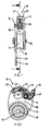
- a pulley 10 comprises a first fixed flange 11 serving to support a first axis 12 of a rotary roller 13, and a second pivot axis 14 of a locking trigger 15.
- the two axes 12, 14 are fixed, and extend parallel to each other in a direction perpendicular to the first flange 11.
- the cylindrical roller 13 is mounted to rotate freely about the first axis 12, and is provided with its periphery of an annular groove 16 for guiding the rope.
- the pivoting trigger 15 is provided with a braking surface 17 for pressing the rope against the roller 13 to constitute a blocker integrated in the space 18 between the two shafts 12, 14.
- the braking surface 17 comprises a plurality of pins slanted to enhance the locking effect of the rope when the blocker is active.
- a spring (not shown) urges the trigger 15 towards the roller 13.
- a second mobile flange 19 is tiltably mounted on the end of the first axis 12 between a closed position and an open position.
- the open position of the second flange 19 allows the establishment of the rope, after moving the trigger 15 to the inactive position, moving it away from the roller 13.
- the rope In the closed position of the second flange 19, the rope is wound in a loop on the roller 13, and is trapped in the transverse gap formed between the flanges 11, 19 parallel.
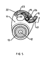
- the first flange 11 has a first circular orifice 20 located near the second axis 14, and above the rotating roller 13.
- the second flange 19 is provided with a second circular orifice 21, which comes into alignment with the first orifice 20 when the two flanges 11, 19 are positioned in the closed position. It is then possible to introduce a carabiner attachment to maintain the flanges 11, 19 in this position by preventing inadvertent tilting.
- the stud 22 is equipped with a latch 23 pivotable about an axis 24 between a locked position ( figures 2 , 4 and 5 ), and an unlocked position ( figure 3 ).
- the pivot axis 24 of the latch 23 is parallel to the second axis 14 of the trigger 15.
- the latch 23 comprises a notch 25 in which can engage a pin 26 of the trigger 15 to ensure its locking in the inactive position of the figure 2 .
- a spring 27 biases the latch 23 to the locked up position. In this position, the latch 23 does not project from the stud 22.
- the second flange 19 is tilted towards the open position for the positioning of the rope in the groove 16 at the upper part of the rotary roller 13.
- the trigger 15 is kept in the inactive position, that is to say spaced from the roller 13, against the counteracting force of its return spring.
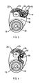
- the figure 2 shows the pulley 10 with the trigger 15 in the locked inactive position.
- the blocker is not operational, and the roller 13 is free to rotate about the first axis 12.
- the stud 26 is housed in the notch 25 of the latch 23, which occupies the locked position. This position of the trigger 15 is stable.
- the figure 3 represents the release of the trigger 15 after pressing the latch 23 which moves in the stud 22 to the unlocked position.
- the pivoting of the latch 23 in the counterclockwise direction causes the notch 25 to recoil and the pin 26 to escape.
- the trigger 15 is in the unlocked inactive position, which is unstable.
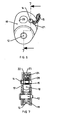
- the latch 23 returns to the locked position, after the return spring has pulled the trigger 15 towards the roller 13.
- the trigger 15 is in the active position which is stable.
- the blocker can thus lock the rope in case of tension appearing on the left strand.
- the latch 23 is always in the locked position, and any forced displacement of the trigger 15 in the unlocking direction (arrow F) is stopped in an intermediate position when the stud 26 comes into engagement with a stop of the latch 23.
- This position is unstable, and maintaining the latch 23 in the locked position, prohibits any continued movement of the trigger 15 to the stable position of the figure 2 .
- the passage to this position becomes possible once the latch 23 is pressed.
Landscapes
- Engineering & Computer Science (AREA)
- Mechanical Engineering (AREA)
- Health & Medical Sciences (AREA)
- General Health & Medical Sciences (AREA)
- Business, Economics & Management (AREA)
- Emergency Management (AREA)
- Emergency Lowering Means (AREA)
- Devices For Conveying Motion By Means Of Endless Flexible Members (AREA)
Claims (7)
- Riemenscheibe mit entriegelbarer Blockiervorrichtung, die umfasst:- eine drehbar an einen ersten Flansch (11) montierte Rolle (13) zum Führen des Seils,- einen Schnapper (15), der schwenkbar ist zwischen einer inaktiven und einer aktiven Position, und zwar jeweils zur Freigabe bzw. Blockierung des Seils gegen die Rolle (13),- und Betätigungsmittel zum Halten des Schnappers (15) in der inaktiven Position, die den Einsatz der Blockiervorrichtung verhindern,dadurch gekennzeichnet, dass die Betätigungsmittel einen am ersten Flansch (11) befestigten Riegel (23) umfassen der geeignet ist, aus einer verriegelten in eine entriegelte Position bewegt zu werden, um das Bewegen des Schnappers (15) in die inaktive Position zu ermöglichten.
- Riemenscheibe mit Blockiervorrichtung nach Anspruch 1, dadurch gekennzeichnet, dass der Riegel (23) um eine Achse (24) schwenkbar ist und mittels einer Rückholfeder (27) in die verriegelte Position gezogen wird.
- Riemenscheibe mit Blockiervorrichtung nach Anspruch 2, dadurch gekennzeichnet, dass der Riegel (23) eine Kerbe (25) umfasst, in die ein Zapfen (26) des Schnappers (15) eingreift, um den Übergang in die inaktive Position zu ermöglichen.
- Riemenscheibe mit Blockiervorrichtung nach Anspruch 2, dadurch gekennzeichnet, dass der Riegel (23) in einem am ersten Flansch (11) angebrachten Klotz (22) ruht, der auch als Halterung für den ersten Durchsteckbolzen (12) der Rolle (13) und für den zweiten Durchsteckbolzen (14) des Schnappers (15) dient.
- Riemenscheibe mit Blockiervorrichtung nach Anspruch 4, dadurch gekennzeichnet, dass ein zweiter beweglicher Flansch (19) schwenkbar an das Ende des ersten Durchsteckbolzens (12) zwischen einer geschlossenen und einer offenen Position montiert ist.
- Riemenscheibe mit Blockiervorrichtung nach Anspruch 5, dadurch gekennzeichnet, dass der erste Flansch (11) eine erste kreisförmige Öffnung (20) umfasst, die sich nahe dem zweiten Durchsteckbolzen (14) des Schnappers (15) und über der drehbaren Rolle (13) befindet, und dass der zweite Flansch (19) mit einer zweiten kreisförmigen Öffnung (21) versehen ist, die in geschlossener Position auf die erste Öffnung (20) des ersten Flansches (11) gefluchtet ist und so das Durchführen eines Karabiners ermöglicht.
- Riemenscheibe mit Blockiervorrichtung nach Anspruch 6, dadurch gekennzeichnet, dass die Schwenkachse (24) des Riegels (23) parallel zum zweiten Durchsteckbolzen (14) des Schnappers (15) ist.
Applications Claiming Priority (1)
| Application Number | Priority Date | Filing Date | Title |
|---|---|---|---|
| FR1003010A FR2962724B1 (fr) | 2010-07-16 | 2010-07-16 | Poulie a bloqueur deverrouillable |
Publications (2)
| Publication Number | Publication Date |
|---|---|
| EP2407413A1 EP2407413A1 (de) | 2012-01-18 |
| EP2407413B1 true EP2407413B1 (de) | 2013-04-10 |
Family
ID=43607887
Family Applications (1)
| Application Number | Title | Priority Date | Filing Date |
|---|---|---|---|
| EP11354038.9A Active EP2407413B1 (de) | 2010-07-16 | 2011-07-07 | Riemenscheibe mit entriegelbarer Blockiervorrichtung |
Country Status (6)
| Country | Link |
|---|---|
| US (1) | US9120654B2 (de) |
| EP (1) | EP2407413B1 (de) |
| CN (1) | CN102371034B (de) |
| AU (1) | AU2011203579B2 (de) |
| ES (1) | ES2411472T3 (de) |
| FR (1) | FR2962724B1 (de) |
Cited By (2)
| Publication number | Priority date | Publication date | Assignee | Title |
|---|---|---|---|---|
| US9126062B2 (en) | 2012-11-16 | 2015-09-08 | Zedel | Safety device on a rope with blocking under load |
| EP3798175B1 (de) * | 2019-09-25 | 2024-09-04 | Zedel | Riemenscheibe mit gesicherter öffnung |
Families Citing this family (12)
| Publication number | Priority date | Publication date | Assignee | Title |
|---|---|---|---|---|
| US9770071B2 (en) * | 2012-08-06 | 2017-09-26 | Kenneth G. Kingery | Parachute cord tie down |
| FR3000898B1 (fr) * | 2013-01-16 | 2015-06-26 | Zedel | Appareil de securite sur corde a voyant indicateur de l'etat indicateur de l'etat de fermeture des flasques |
| US9623269B2 (en) * | 2013-03-14 | 2017-04-18 | Black Diamond Equipment, Ltd. | Systems for assisted braking belay with a cam-clutch mechanism |
| US10221918B2 (en) * | 2015-06-27 | 2019-03-05 | Dark Canyon, Inc. | Rope tension device and method thereof |
| CN108069358B (zh) * | 2016-11-16 | 2020-08-28 | 国网山东省电力公司潍坊供电公司 | 半自动电力设备缓降器 |
| US9878884B1 (en) * | 2016-11-23 | 2018-01-30 | International Safety Components Ltd | Pulley systems for hauling or lowering loads |
| DE202017105449U1 (de) * | 2017-09-08 | 2017-10-18 | Liebherr-Werk Ehingen Gmbh | Hakenflaschengrundkörper |
| WO2019227108A1 (en) * | 2018-05-24 | 2019-11-28 | Du Toit Johan Paul | A descender |
| FR3084264B1 (fr) | 2018-07-24 | 2020-09-18 | Zedel | Descendeur a poulie |
| US10995842B1 (en) * | 2019-01-30 | 2021-05-04 | Summit Rescue, Inc. | Pulley with hinged side plate |
| IT202100025394A1 (it) * | 2021-10-04 | 2023-04-04 | Aludesign Spa | Dispositivo multifunzione dotato di una camma di bloccaggio e di una puleggia per una fune di sicurezza |
| EP4545148B1 (de) * | 2023-10-24 | 2026-02-25 | SKYLOTEC GmbH | Fallschutzvorrichtung |
Family Cites Families (25)
| Publication number | Priority date | Publication date | Assignee | Title |
|---|---|---|---|---|
| US395113A (en) * | 1888-12-25 | Hoisting-tackle | ||
| US473093A (en) * | 1892-04-19 | Bryant r | ||
| US210281A (en) * | 1878-11-26 | Improvement in safety pulley-blocks | ||
| US1304353A (en) * | 1919-05-20 | Launching of ships boats | ||
| US916091A (en) * | 1908-06-18 | 1909-03-23 | George J Batzer | Pulley and rope or cable holder. |
| US1107934A (en) * | 1913-07-24 | 1914-08-18 | Arthur J Hagan | Pulley and lock for cables. |
| US1709910A (en) * | 1928-06-16 | 1929-04-23 | Charles H Gray | Rope clamp |
| US2723834A (en) * | 1953-03-06 | 1955-11-15 | Frederick C Burke | Self-locking safety snatch block |
| US2800300A (en) * | 1955-05-23 | 1957-07-23 | Joy Mfg Co | Sheave block construction |
| US3662992A (en) * | 1970-05-28 | 1972-05-16 | Murray B Vittert | Tackle block |
| US3777856A (en) * | 1971-10-06 | 1973-12-11 | Republic Corp | Roving counter and brake |
| JPS5442276U (de) * | 1977-08-31 | 1979-03-22 | ||
| JPS5442276A (en) | 1977-09-09 | 1979-04-04 | Jii Kei Shiyotsupu Kk | Method of making bottole opener from synthetic resin |
| FR2647099B1 (fr) * | 1989-05-19 | 1991-07-19 | Petzl Ets | Dispositif d'assurance autobloquant pour corde |
| US5056760A (en) * | 1990-04-02 | 1991-10-15 | The United States Of America As Represented By The Secretary Of The Navy | T-slot sheave |
| FR2671489A1 (fr) * | 1991-01-16 | 1992-07-17 | Caron Gilbert | Dispositif a poulie frein pour le secours et la pratique des activites de montagne et de speleologie. |
| US5348117A (en) * | 1992-08-12 | 1994-09-20 | Pickering Gregory R | Rescue system |
| US5664640A (en) * | 1995-02-03 | 1997-09-09 | Smith; Daniel I. | Ascending cam |
| FR2748078B1 (fr) | 1996-04-25 | 1998-06-12 | Zedel | Poulie a flasque pivotant et a bloqueur integre |
| US6244570B1 (en) * | 1998-10-05 | 2001-06-12 | Jeff Habberstad | High speed safety block assembly |
| US6182946B1 (en) * | 1999-05-17 | 2001-02-06 | Darin Rutherford | Tree stand hoist assembly and casing therefor having identical mating halves |
| US7658264B2 (en) * | 2005-03-16 | 2010-02-09 | Kirk Martin Mauthner | Combination descender, pulley and force limiting rope brake |
| FR2898506B1 (fr) * | 2006-03-15 | 2008-05-30 | Zedel Soc Par Actions Simplifi | Appareil multifonctionnel d'assurage pour corde |
| FR2919196B1 (fr) * | 2007-07-26 | 2009-10-09 | Zedel Soc Par Actions Simplifi | Descendeur autobloquant a poignee debrayable. |
| US7445195B1 (en) * | 2007-11-09 | 2008-11-04 | Han-Ching Huang | Pulley |
-
2010
- 2010-07-16 FR FR1003010A patent/FR2962724B1/fr not_active Expired - Fee Related
-
2011
- 2011-07-07 EP EP11354038.9A patent/EP2407413B1/de active Active
- 2011-07-07 ES ES11354038T patent/ES2411472T3/es active Active
- 2011-07-14 AU AU2011203579A patent/AU2011203579B2/en active Active
- 2011-07-18 CN CN201110315925.1A patent/CN102371034B/zh active Active
- 2011-07-18 US US13/184,840 patent/US9120654B2/en active Active
Cited By (2)
| Publication number | Priority date | Publication date | Assignee | Title |
|---|---|---|---|---|
| US9126062B2 (en) | 2012-11-16 | 2015-09-08 | Zedel | Safety device on a rope with blocking under load |
| EP3798175B1 (de) * | 2019-09-25 | 2024-09-04 | Zedel | Riemenscheibe mit gesicherter öffnung |
Also Published As
| Publication number | Publication date |
|---|---|
| CN102371034B (zh) | 2015-07-08 |
| AU2011203579A1 (en) | 2012-02-02 |
| FR2962724A1 (fr) | 2012-01-20 |
| US9120654B2 (en) | 2015-09-01 |
| FR2962724B1 (fr) | 2012-08-03 |
| ES2411472T3 (es) | 2013-07-05 |
| CN102371034A (zh) | 2012-03-14 |
| US20120012800A1 (en) | 2012-01-19 |
| AU2011203579B2 (en) | 2015-10-29 |
| EP2407413A1 (de) | 2012-01-18 |
Similar Documents
| Publication | Publication Date | Title |
|---|---|---|
| EP2407413B1 (de) | Riemenscheibe mit entriegelbarer Blockiervorrichtung | |
| EP0803268B1 (de) | Scheibe mit Drehflansch und integrierter Klemme | |
| EP2735341B1 (de) | Seilsicherungsgerät mit Verschlussmöglichkeit unter Belastung | |
| EP0593369B1 (de) | Sicherheitsabseilvorrichtung | |
| EP0688581B1 (de) | Entkuppelbares selbstblockierendes Abseilgerät | |
| EP2754465B1 (de) | Sicherheitssystem zur Fallsicherung und Blockierung am Seil | |
| EP2018894B1 (de) | Selbstblockierendes Abseilgerät mit entkoppelbarem Griff | |
| EP1834672B1 (de) | Mehrfunktionsgerät zur Sicherung eines Seils | |
| EP1465507B1 (de) | Schnalle zur selbstverriegelung und einstellungsfestlegung eines gürtels | |
| FR2938771A1 (fr) | Dispositif bloqueur a came pour l'assurage sur corde fixe | |
| WO2005014962A2 (fr) | Verrou destine a relier deux panneaux d’une strcuture d’aeroplane | |
| FR2927027A1 (fr) | Mecanisme d'articulation a elements de verrouillage pivotant pour siege de vehicule et siege comportant un tel mecanisme | |
| EP2754466A1 (de) | Sicherheitssystem zur Fallsicherung mit Blockierfunktion am Seil | |
| FR2694203A1 (fr) | Mousqueton à galet de verrouillage automatique. | |
| EP2003268B1 (de) | Verbindungs- und Befestigungselement einer Struktur an einer Wand, dazugehörige Struktur und entsprechende Gesamtstruktur | |
| FR2975052A1 (fr) | Ensemble d'articulation pour siege de vehicule et siege de vehicule comprenant l'ensemble d'articulation | |
| FR3023726A1 (fr) | Bloqueur pour la remontee sur corde | |
| WO2014041308A1 (fr) | Longe de securite | |
| FR3150123A1 (fr) | Dispositif de blocage de corde et procédé d’utilisation | |
| FR3101253A1 (fr) | Dispositif antichute, de préférence à rappel automatique | |
| WO2009122105A1 (fr) | Dispositif de verrouillage d'une sangle de ceinture de securite sans pene | |
| EP0094284A1 (de) | Verriegelungsvorrichtung, insbesondere für Ersatzradhalterung | |
| FR2995840A1 (fr) | Siege automobile pour enfant | |
| FR3021500A1 (fr) | Laisse automatique retractable | |
| EP1059228A1 (de) | Tauklemmer |
Legal Events
| Date | Code | Title | Description |
|---|---|---|---|
| AK | Designated contracting states |
Kind code of ref document: A1 Designated state(s): AL AT BE BG CH CY CZ DE DK EE ES FI FR GB GR HR HU IE IS IT LI LT LU LV MC MK MT NL NO PL PT RO RS SE SI SK SM TR |
|
| AX | Request for extension of the european patent |
Extension state: BA ME |
|
| PUAI | Public reference made under article 153(3) epc to a published international application that has entered the european phase |
Free format text: ORIGINAL CODE: 0009012 |
|
| 17P | Request for examination filed |
Effective date: 20120717 |
|
| GRAP | Despatch of communication of intention to grant a patent |
Free format text: ORIGINAL CODE: EPIDOSNIGR1 |
|
| GRAS | Grant fee paid |
Free format text: ORIGINAL CODE: EPIDOSNIGR3 |
|
| GRAA | (expected) grant |
Free format text: ORIGINAL CODE: 0009210 |
|
| AK | Designated contracting states |
Kind code of ref document: B1 Designated state(s): AL AT BE BG CH CY CZ DE DK EE ES FI FR GB GR HR HU IE IS IT LI LT LU LV MC MK MT NL NO PL PT RO RS SE SI SK SM TR |
|
| REG | Reference to a national code |
Ref country code: GB Ref legal event code: FG4D Free format text: NOT ENGLISH |
|
| REG | Reference to a national code |
Ref country code: AT Ref legal event code: REF Ref document number: 605885 Country of ref document: AT Kind code of ref document: T Effective date: 20130415 Ref country code: CH Ref legal event code: EP |
|
| REG | Reference to a national code |
Ref country code: IE Ref legal event code: FG4D Free format text: LANGUAGE OF EP DOCUMENT: FRENCH |
|
| REG | Reference to a national code |
Ref country code: DE Ref legal event code: R096 Ref document number: 602011001323 Country of ref document: DE Effective date: 20130606 |
|
| REG | Reference to a national code |
Ref country code: CH Ref legal event code: NV Representative=s name: CABINET ROLAND NITHARDT CONSEILS EN PROPRIETE , CH |
|
| REG | Reference to a national code |
Ref country code: ES Ref legal event code: FG2A Ref document number: 2411472 Country of ref document: ES Kind code of ref document: T3 Effective date: 20130705 |
|
| PG25 | Lapsed in a contracting state [announced via postgrant information from national office to epo] |
Ref country code: SI Free format text: LAPSE BECAUSE OF FAILURE TO SUBMIT A TRANSLATION OF THE DESCRIPTION OR TO PAY THE FEE WITHIN THE PRESCRIBED TIME-LIMIT Effective date: 20130410 |
|
| REG | Reference to a national code |
Ref country code: AT Ref legal event code: MK05 Ref document number: 605885 Country of ref document: AT Kind code of ref document: T Effective date: 20130410 |
|
| REG | Reference to a national code |
Ref country code: NL Ref legal event code: VDEP Effective date: 20130410 Ref country code: LT Ref legal event code: MG4D |
|
| PG25 | Lapsed in a contracting state [announced via postgrant information from national office to epo] |
Ref country code: NL Free format text: LAPSE BECAUSE OF FAILURE TO SUBMIT A TRANSLATION OF THE DESCRIPTION OR TO PAY THE FEE WITHIN THE PRESCRIBED TIME-LIMIT Effective date: 20130410 Ref country code: AT Free format text: LAPSE BECAUSE OF FAILURE TO SUBMIT A TRANSLATION OF THE DESCRIPTION OR TO PAY THE FEE WITHIN THE PRESCRIBED TIME-LIMIT Effective date: 20130410 Ref country code: LT Free format text: LAPSE BECAUSE OF FAILURE TO SUBMIT A TRANSLATION OF THE DESCRIPTION OR TO PAY THE FEE WITHIN THE PRESCRIBED TIME-LIMIT Effective date: 20130410 Ref country code: GR Free format text: LAPSE BECAUSE OF FAILURE TO SUBMIT A TRANSLATION OF THE DESCRIPTION OR TO PAY THE FEE WITHIN THE PRESCRIBED TIME-LIMIT Effective date: 20130711 Ref country code: FI Free format text: LAPSE BECAUSE OF FAILURE TO SUBMIT A TRANSLATION OF THE DESCRIPTION OR TO PAY THE FEE WITHIN THE PRESCRIBED TIME-LIMIT Effective date: 20130410 Ref country code: PT Free format text: LAPSE BECAUSE OF FAILURE TO SUBMIT A TRANSLATION OF THE DESCRIPTION OR TO PAY THE FEE WITHIN THE PRESCRIBED TIME-LIMIT Effective date: 20130812 Ref country code: SE Free format text: LAPSE BECAUSE OF FAILURE TO SUBMIT A TRANSLATION OF THE DESCRIPTION OR TO PAY THE FEE WITHIN THE PRESCRIBED TIME-LIMIT Effective date: 20130410 Ref country code: NO Free format text: LAPSE BECAUSE OF FAILURE TO SUBMIT A TRANSLATION OF THE DESCRIPTION OR TO PAY THE FEE WITHIN THE PRESCRIBED TIME-LIMIT Effective date: 20130710 Ref country code: IS Free format text: LAPSE BECAUSE OF FAILURE TO SUBMIT A TRANSLATION OF THE DESCRIPTION OR TO PAY THE FEE WITHIN THE PRESCRIBED TIME-LIMIT Effective date: 20130810 |
|
| PG25 | Lapsed in a contracting state [announced via postgrant information from national office to epo] |
Ref country code: LV Free format text: LAPSE BECAUSE OF FAILURE TO SUBMIT A TRANSLATION OF THE DESCRIPTION OR TO PAY THE FEE WITHIN THE PRESCRIBED TIME-LIMIT Effective date: 20130410 Ref country code: HR Free format text: LAPSE BECAUSE OF FAILURE TO SUBMIT A TRANSLATION OF THE DESCRIPTION OR TO PAY THE FEE WITHIN THE PRESCRIBED TIME-LIMIT Effective date: 20130410 Ref country code: CY Free format text: LAPSE BECAUSE OF FAILURE TO SUBMIT A TRANSLATION OF THE DESCRIPTION OR TO PAY THE FEE WITHIN THE PRESCRIBED TIME-LIMIT Effective date: 20130410 Ref country code: RS Free format text: LAPSE BECAUSE OF FAILURE TO SUBMIT A TRANSLATION OF THE DESCRIPTION OR TO PAY THE FEE WITHIN THE PRESCRIBED TIME-LIMIT Effective date: 20130410 Ref country code: BG Free format text: LAPSE BECAUSE OF FAILURE TO SUBMIT A TRANSLATION OF THE DESCRIPTION OR TO PAY THE FEE WITHIN THE PRESCRIBED TIME-LIMIT Effective date: 20130710 Ref country code: PL Free format text: LAPSE BECAUSE OF FAILURE TO SUBMIT A TRANSLATION OF THE DESCRIPTION OR TO PAY THE FEE WITHIN THE PRESCRIBED TIME-LIMIT Effective date: 20130410 |
|
| BERE | Be: lapsed |
Owner name: ZEDEL Effective date: 20130731 |
|
| PG25 | Lapsed in a contracting state [announced via postgrant information from national office to epo] |
Ref country code: DK Free format text: LAPSE BECAUSE OF FAILURE TO SUBMIT A TRANSLATION OF THE DESCRIPTION OR TO PAY THE FEE WITHIN THE PRESCRIBED TIME-LIMIT Effective date: 20130410 Ref country code: EE Free format text: LAPSE BECAUSE OF FAILURE TO SUBMIT A TRANSLATION OF THE DESCRIPTION OR TO PAY THE FEE WITHIN THE PRESCRIBED TIME-LIMIT Effective date: 20130410 Ref country code: SK Free format text: LAPSE BECAUSE OF FAILURE TO SUBMIT A TRANSLATION OF THE DESCRIPTION OR TO PAY THE FEE WITHIN THE PRESCRIBED TIME-LIMIT Effective date: 20130410 |
|
| PLBE | No opposition filed within time limit |
Free format text: ORIGINAL CODE: 0009261 |
|
| STAA | Information on the status of an ep patent application or granted ep patent |
Free format text: STATUS: NO OPPOSITION FILED WITHIN TIME LIMIT |
|
| PG25 | Lapsed in a contracting state [announced via postgrant information from national office to epo] |
Ref country code: RO Free format text: LAPSE BECAUSE OF FAILURE TO SUBMIT A TRANSLATION OF THE DESCRIPTION OR TO PAY THE FEE WITHIN THE PRESCRIBED TIME-LIMIT Effective date: 20130410 Ref country code: MC Free format text: LAPSE BECAUSE OF FAILURE TO SUBMIT A TRANSLATION OF THE DESCRIPTION OR TO PAY THE FEE WITHIN THE PRESCRIBED TIME-LIMIT Effective date: 20130410 |
|
| 26N | No opposition filed |
Effective date: 20140113 |
|
| REG | Reference to a national code |
Ref country code: IE Ref legal event code: MM4A |
|
| REG | Reference to a national code |
Ref country code: DE Ref legal event code: R097 Ref document number: 602011001323 Country of ref document: DE Effective date: 20140113 |
|
| PG25 | Lapsed in a contracting state [announced via postgrant information from national office to epo] |
Ref country code: BE Free format text: LAPSE BECAUSE OF NON-PAYMENT OF DUE FEES Effective date: 20130731 |
|
| PG25 | Lapsed in a contracting state [announced via postgrant information from national office to epo] |
Ref country code: IE Free format text: LAPSE BECAUSE OF NON-PAYMENT OF DUE FEES Effective date: 20130707 |
|
| PG25 | Lapsed in a contracting state [announced via postgrant information from national office to epo] |
Ref country code: SM Free format text: LAPSE BECAUSE OF FAILURE TO SUBMIT A TRANSLATION OF THE DESCRIPTION OR TO PAY THE FEE WITHIN THE PRESCRIBED TIME-LIMIT Effective date: 20130410 |
|
| PG25 | Lapsed in a contracting state [announced via postgrant information from national office to epo] |
Ref country code: MT Free format text: LAPSE BECAUSE OF FAILURE TO SUBMIT A TRANSLATION OF THE DESCRIPTION OR TO PAY THE FEE WITHIN THE PRESCRIBED TIME-LIMIT Effective date: 20130410 Ref country code: TR Free format text: LAPSE BECAUSE OF FAILURE TO SUBMIT A TRANSLATION OF THE DESCRIPTION OR TO PAY THE FEE WITHIN THE PRESCRIBED TIME-LIMIT Effective date: 20130410 |
|
| PG25 | Lapsed in a contracting state [announced via postgrant information from national office to epo] |
Ref country code: MK Free format text: LAPSE BECAUSE OF FAILURE TO SUBMIT A TRANSLATION OF THE DESCRIPTION OR TO PAY THE FEE WITHIN THE PRESCRIBED TIME-LIMIT Effective date: 20130410 Ref country code: LU Free format text: LAPSE BECAUSE OF NON-PAYMENT OF DUE FEES Effective date: 20130707 Ref country code: HU Free format text: LAPSE BECAUSE OF FAILURE TO SUBMIT A TRANSLATION OF THE DESCRIPTION OR TO PAY THE FEE WITHIN THE PRESCRIBED TIME-LIMIT; INVALID AB INITIO Effective date: 20110707 |
|
| REG | Reference to a national code |
Ref country code: FR Ref legal event code: PLFP Year of fee payment: 6 |
|
| REG | Reference to a national code |
Ref country code: FR Ref legal event code: PLFP Year of fee payment: 7 |
|
| REG | Reference to a national code |
Ref country code: FR Ref legal event code: PLFP Year of fee payment: 8 |
|
| PG25 | Lapsed in a contracting state [announced via postgrant information from national office to epo] |
Ref country code: AL Free format text: LAPSE BECAUSE OF FAILURE TO SUBMIT A TRANSLATION OF THE DESCRIPTION OR TO PAY THE FEE WITHIN THE PRESCRIBED TIME-LIMIT Effective date: 20130410 |
|
| PGFP | Annual fee paid to national office [announced via postgrant information from national office to epo] |
Ref country code: CZ Payment date: 20250624 Year of fee payment: 15 |
|
| PGFP | Annual fee paid to national office [announced via postgrant information from national office to epo] |
Ref country code: ES Payment date: 20250819 Year of fee payment: 15 |
|
| PGFP | Annual fee paid to national office [announced via postgrant information from national office to epo] |
Ref country code: DE Payment date: 20250722 Year of fee payment: 15 |
|
| PGFP | Annual fee paid to national office [announced via postgrant information from national office to epo] |
Ref country code: IT Payment date: 20250731 Year of fee payment: 15 |
|
| PGFP | Annual fee paid to national office [announced via postgrant information from national office to epo] |
Ref country code: GB Payment date: 20250724 Year of fee payment: 15 |
|
| PGFP | Annual fee paid to national office [announced via postgrant information from national office to epo] |
Ref country code: FR Payment date: 20250723 Year of fee payment: 15 |
|
| PGFP | Annual fee paid to national office [announced via postgrant information from national office to epo] |
Ref country code: CH Payment date: 20250801 Year of fee payment: 15 |