EP2407413B1 - Pulley with unlockable blocker - Google Patents
Pulley with unlockable blocker Download PDFInfo
- Publication number
- EP2407413B1 EP2407413B1 EP11354038.9A EP11354038A EP2407413B1 EP 2407413 B1 EP2407413 B1 EP 2407413B1 EP 11354038 A EP11354038 A EP 11354038A EP 2407413 B1 EP2407413 B1 EP 2407413B1
- Authority
- EP
- European Patent Office
- Prior art keywords
- trigger
- pulley
- flange
- spindle
- plate
- Prior art date
- Legal status (The legal status is an assumption and is not a legal conclusion. Google has not performed a legal analysis and makes no representation as to the accuracy of the status listed.)
- Active
Links
- 230000000903 blocking effect Effects 0.000 description 3
- 241000251556 Chordata Species 0.000 description 2
- 238000006073 displacement reaction Methods 0.000 description 1
- 230000000694 effects Effects 0.000 description 1
- 230000002401 inhibitory effect Effects 0.000 description 1
- 230000007704 transition Effects 0.000 description 1
Images

Classifications
-
- B—PERFORMING OPERATIONS; TRANSPORTING
- B66—HOISTING; LIFTING; HAULING
- B66D—CAPSTANS; WINCHES; TACKLES, e.g. PULLEY BLOCKS; HOISTS
- B66D3/00—Portable or mobile lifting or hauling appliances
- B66D3/04—Pulley blocks or like devices in which force is applied to a rope, cable, or chain which passes over one or more pulleys, e.g. to obtain mechanical advantage
- B66D3/046—Openable pulley blocks
-
- A—HUMAN NECESSITIES
- A62—LIFE-SAVING; FIRE-FIGHTING
- A62B—DEVICES, APPARATUS OR METHODS FOR LIFE-SAVING
- A62B1/00—Devices for lowering persons from buildings or the like
- A62B1/06—Devices for lowering persons from buildings or the like by making use of rope-lowering devices
- A62B1/08—Devices for lowering persons from buildings or the like by making use of rope-lowering devices with brake mechanisms for the winches or pulleys
- A62B1/10—Devices for lowering persons from buildings or the like by making use of rope-lowering devices with brake mechanisms for the winches or pulleys mechanically operated
-
- B—PERFORMING OPERATIONS; TRANSPORTING
- B66—HOISTING; LIFTING; HAULING
- B66D—CAPSTANS; WINCHES; TACKLES, e.g. PULLEY BLOCKS; HOISTS
- B66D3/00—Portable or mobile lifting or hauling appliances
- B66D3/04—Pulley blocks or like devices in which force is applied to a rope, cable, or chain which passes over one or more pulleys, e.g. to obtain mechanical advantage
- B66D3/06—Pulley blocks or like devices in which force is applied to a rope, cable, or chain which passes over one or more pulleys, e.g. to obtain mechanical advantage with more than one pulley
- B66D3/10—Applications of braking or detent devices
-
- B—PERFORMING OPERATIONS; TRANSPORTING
- B66—HOISTING; LIFTING; HAULING
- B66D—CAPSTANS; WINCHES; TACKLES, e.g. PULLEY BLOCKS; HOISTS
- B66D5/00—Braking or detent devices characterised by application to lifting or hoisting gear, e.g. for controlling the lowering of loads
- B66D5/02—Crane, lift hoist, or winch brakes operating on drums, barrels, or ropes
- B66D5/16—Crane, lift hoist, or winch brakes operating on drums, barrels, or ropes for action on ropes or cables
Definitions
- the invention relates to an unlockable locking pulley, comprising a roller rotatably mounted on a first flange for guiding the rope, a pivoting trigger between an inactive position and an active position, respectively to unlock and lock the rope against the rope. roller, and control means for holding the trigger in the inactive position inhibiting the action of the blocker.
- the document EP 803268 of the Applicant describes an integrated blocking pulley of the kind mentioned.
- the inactive position the use of the apparatus is reduced to a conventional block without blocker, since the trigger is locked while being kept away from the rotating roller.
- the active position the trigger is free and is likely to block the rope.
- the control means for maintaining the pulley in the inactive position are part of the trigger as a result of the introduction of an additional karabiner in a lockout lock provided in the trigger when the latter is in the remote position.
- the braking and jamming surface of the trigger is then separated from the roller.
- This additional carabiner in addition to the carabiner attachment nevertheless complicates the maneuvering operations of the pulley.
- the object of the invention is to provide an integrated blocking pulley having a small footprint, and can easily be manipulated.
- the blocking pulley according to the invention is characterized in that the control means comprise a lock fixed on the first flange, and able to be actuated from a locked position to an unlocked position to allow the trigger to be moved to the position inactive.
- the latch is pivotable about an axis, and is biased towards the locked position by a return spring.
- the lock has a notch in which engages a pin of the trigger to allow passage to the inactive position.
- the latch is housed in a stud fixed on a first flange, which also serves as a support for the first axis of the roller and the second axis of the trigger.
- a second mobile flange is advantageously mounted to tilt over the end of the first axis between a closed position and an open position.
- the first flange has a first circular orifice located near the second axis of the trigger and above the rotary roller.
- the second flange is provided with a second circular orifice coming into alignment in closed position with the first port of the first flange, allowing the passage of a carabiner attachment.
- a pulley 10 comprises a first fixed flange 11 serving to support a first axis 12 of a rotary roller 13, and a second pivot axis 14 of a locking trigger 15.
- the two axes 12, 14 are fixed, and extend parallel to each other in a direction perpendicular to the first flange 11.
- the cylindrical roller 13 is mounted to rotate freely about the first axis 12, and is provided with its periphery of an annular groove 16 for guiding the rope.
- the pivoting trigger 15 is provided with a braking surface 17 for pressing the rope against the roller 13 to constitute a blocker integrated in the space 18 between the two shafts 12, 14.
- the braking surface 17 comprises a plurality of pins slanted to enhance the locking effect of the rope when the blocker is active.
- a spring (not shown) urges the trigger 15 towards the roller 13.
- a second mobile flange 19 is tiltably mounted on the end of the first axis 12 between a closed position and an open position.
- the open position of the second flange 19 allows the establishment of the rope, after moving the trigger 15 to the inactive position, moving it away from the roller 13.
- the rope In the closed position of the second flange 19, the rope is wound in a loop on the roller 13, and is trapped in the transverse gap formed between the flanges 11, 19 parallel.
- the first flange 11 has a first circular orifice 20 located near the second axis 14, and above the rotating roller 13.
- the second flange 19 is provided with a second circular orifice 21, which comes into alignment with the first orifice 20 when the two flanges 11, 19 are positioned in the closed position. It is then possible to introduce a carabiner attachment to maintain the flanges 11, 19 in this position by preventing inadvertent tilting.
- the stud 22 is equipped with a latch 23 pivotable about an axis 24 between a locked position ( figures 2 , 4 and 5 ), and an unlocked position ( figure 3 ).
- the pivot axis 24 of the latch 23 is parallel to the second axis 14 of the trigger 15.
- the latch 23 comprises a notch 25 in which can engage a pin 26 of the trigger 15 to ensure its locking in the inactive position of the figure 2 .
- a spring 27 biases the latch 23 to the locked up position. In this position, the latch 23 does not project from the stud 22.
- the second flange 19 is tilted towards the open position for the positioning of the rope in the groove 16 at the upper part of the rotary roller 13.
- the trigger 15 is kept in the inactive position, that is to say spaced from the roller 13, against the counteracting force of its return spring.
- the figure 2 shows the pulley 10 with the trigger 15 in the locked inactive position.
- the blocker is not operational, and the roller 13 is free to rotate about the first axis 12.
- the stud 26 is housed in the notch 25 of the latch 23, which occupies the locked position. This position of the trigger 15 is stable.
- the figure 3 represents the release of the trigger 15 after pressing the latch 23 which moves in the stud 22 to the unlocked position.
- the pivoting of the latch 23 in the counterclockwise direction causes the notch 25 to recoil and the pin 26 to escape.
- the trigger 15 is in the unlocked inactive position, which is unstable.
- the latch 23 returns to the locked position, after the return spring has pulled the trigger 15 towards the roller 13.
- the trigger 15 is in the active position which is stable.
- the blocker can thus lock the rope in case of tension appearing on the left strand.
- the latch 23 is always in the locked position, and any forced displacement of the trigger 15 in the unlocking direction (arrow F) is stopped in an intermediate position when the stud 26 comes into engagement with a stop of the latch 23.
- This position is unstable, and maintaining the latch 23 in the locked position, prohibits any continued movement of the trigger 15 to the stable position of the figure 2 .
- the passage to this position becomes possible once the latch 23 is pressed.
Description
L'invention est relative à une poulie à bloqueur déverrouillable, comprenant un galet monté à rotation sur un premier flasque pour le guidage de la corde, une gâchette pivotante entre une position inactive et une position active, respectivement pour débloquer et bloquer la corde contre le galet, et des moyens de commande pour maintenir la gâchette dans la position inactive inhibant l'action du bloqueur.The invention relates to an unlockable locking pulley, comprising a roller rotatably mounted on a first flange for guiding the rope, a pivoting trigger between an inactive position and an active position, respectively to unlock and lock the rope against the rope. roller, and control means for holding the trigger in the inactive position inhibiting the action of the blocker.
Le document
L'objet de l'invention consiste à réaliser une poulie à bloqueur intégré ayant un encombrement réduit, et pouvant facilement être manipulée.The object of the invention is to provide an integrated blocking pulley having a small footprint, and can easily be manipulated.
La poulie à bloqueur selon l'invention est caractérisée en ce que les moyens de commande comportent un verrou fixé sur le premier flasque, et apte à être actionné d'une position verrouillée vers une position déverrouillée pour permettre le déplacement de la gâchette vers la position inactive.The blocking pulley according to the invention is characterized in that the control means comprise a lock fixed on the first flange, and able to be actuated from a locked position to an unlocked position to allow the trigger to be moved to the position inactive.
Toute tentative de déplacement forcé de la gâchette dans le sens du déblocage est stoppée dans une position intermédiaire, laquelle est instable aussi longtemps que le verrou demeure dans la position verrouillée. Le déplacement poursuivi de la gâchette vers la position inactive stable est donc interdit. Le passage vers cette position inactive redevient possible dès que l'on appui sur le verrou.Any attempt to forcibly move the trigger in the unlocking direction is stopped in an intermediate position, which is unstable as long as the latch remains in the locked position. Continued movement of the trigger to the stable inactive position is therefore prohibited. The transition to this inactive position becomes possible once the lock is pressed.
Selon un mode de réalisation préférentiel, le verrou est pivotant autour d'un axe, et est sollicité vers la position verrouillée par un ressort de rappel. Le verrou comporte une encoche dans laquelle s'engage un téton de la gâchette pour autoriser le passage vers la position inactive.According to a preferred embodiment, the latch is pivotable about an axis, and is biased towards the locked position by a return spring. The lock has a notch in which engages a pin of the trigger to allow passage to the inactive position.
Selon une caractéristique de l'invention, le verrou est logé dans un plot fixé sur un premier flasque, lequel sert également de support au premier axe du galet et au deuxième axe de la gâchette.According to a feature of the invention, the latch is housed in a stud fixed on a first flange, which also serves as a support for the first axis of the roller and the second axis of the trigger.
Un deuxième flasque mobile est avantageusement monté à basculement sur l'extrémité du premier axe entre une position fermée et une position ouverte. Le premier flasque comporte un premier orifice circulaire situé près du deuxième axe de la gâchette et au-dessus du galet rotatif. Le deuxième flasque est pourvu d'un deuxième orifice circulaire venant en alignement en position fermée avec le premier orifice du premier flasque, en autorisant le passage d'un mousqueton d'attache.A second mobile flange is advantageously mounted to tilt over the end of the first axis between a closed position and an open position. The first flange has a first circular orifice located near the second axis of the trigger and above the rotary roller. The second flange is provided with a second circular orifice coming into alignment in closed position with the first port of the first flange, allowing the passage of a carabiner attachment.
D'autres avantages et caractéristiques ressortiront plus clairement de la description qui va suivre d'un mode de réalisation de l'invention donné à titre d'exemple non limitatif et représenté aux dessins annexés, dans lesquels :
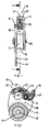
- la
figure 1 est une vue de profil de la poulie selon l'invention, le deuxième flasque se trouvant en position ouverte pour la mis e en place de la corde sur le galet rotatif ; - la
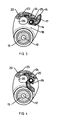
figure 2 est une vue en coupe verticale selon la ligne 2-2 de lafigure1 , la gâchette se trouvant en position inactive et le verrou en position verrouillée ; - la
figure 3 montre une vue identique de lafigure 2 lorsque le verrou est actionné vers la position déverrouillée ; - la
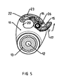
figure 4 représente une vue identique de lafigure 3 lorsque la gâchette est libre et prête à coincer la corde contre le galet ; - la
figure 5 est une vue identique de lafigure 4 lors d'une tentative forcé d'ouverture de la gâchette, laquelle est bloquée dans une position intermédiaire lorsque le verrou est verrouillée ; - la
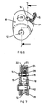
figure 6 illustre une vue en élévation de la poulie, le deuxième flasque basculant étant enlevé ; - la
figure 7 est une vue en coupe selon la ligne 7-7 de lafigure 6 ; - la
figure 8 est une vue en perspective de la poulie, le deuxième flasque basculant étant en position ouverte, et la gâchette en position inactive écartée du galet.
- the
figure 1 is a side view of the pulley according to the invention, the second flange being in the open position for the establishment of the rope on the rotary roller; - the
figure 2 is a vertical sectional view along line 2-2 of thefigure 1 , the trigger being in the inactive position and the lock in the locked position; - the
figure 3 shows an identical view of thefigure 2 when the latch is actuated to the unlocked position; - the
figure 4 represents an identical view of thefigure 3 when the trigger is free and ready to wedge the rope against the roller; - the
figure 5 is an identical view of thefigure 4 during a forced attempt to open the trigger, which is locked in an intermediate position when the lock is locked; - the
figure 6 illustrates an elevational view of the pulley, the second tilting flange being removed; - the
figure 7 is a sectional view along the line 7-7 of thefigure 6 ; - the
figure 8 is a perspective view of the pulley, the second tilting flange being in the open position, and the trigger in the inactive position spaced from the roller.
Sur les figures, une poulie 10 comporte un premier flasque 11 fixe servant de support à un premier axe 12 d'un galet 13 rotatif, et un deuxième axe 14 de pivotement d'une gâchette 15 de blocage.In the figures, a
Les deux axes 12, 14 sont fixes, et s'étendent parallèlement l'un à l'autre selon une direction perpendiculaire au premier flasque 11. Le galet 13 cylindrique est monté à rotation libre autour du premier axe 12, et est muni à sa périphérie d'une gorge 16 annulaire pour le guidage de la corde.The two
La gâchette 15 pivotante est pourvue d'une surface de freinage 17 destinée à presser la corde contre le galet 13 pour constituer un bloqueur intégré dans l'espace 18 entre les deux axes 12, 14. La surface de freinage 17 comporte une pluralité de picots inclinés destinés à renforcer l'effet de blocage de la corde lorsque le bloqueur est actif. Un ressort (non représenté) sollicite la gâchette 15 vers le galet 13.The
Un deuxième flasque 19 mobile est monté à basculement sur l'extrémité du premier axe 12 entre une position fermée et une position ouverte. La position ouverte du deuxième flasque 19 permet la mise en place de la corde, après avoir déplacé la gâchette 15 vers la position inactive, l'écartant du galet 13. Dans la position fermée du deuxième flasque 19, la corde est enroulée en boucle sur le galet 13, et est emprisonnée dans l'intervalle transversal ménagé entre les flasques 11, 19 parallèles.A second
Le premier flasque 11 comporte un premier orifice 20 circulaire situé près du deuxième axe 14, et au-dessus du galet 13 rotatif. Le deuxième flasque 19 est doté d'un deuxième orifice 21 circulaire, lequel vient en alignement avec le premier orifice 20 lorsque les deux flasques 11, 19 sont positionnés en position fermée. Il est alors possible d'y introduire un mousqueton d'attache pour maintenir les flasques 11, 19 dans cette position en empêchant tout basculement intempestif.The
Au-dessus du premier orifice 20, se trouve un plot 22 fixé au premier flasque 11, en occupant l'intervalle transversal entre les flasques 11, 19. Le plot 22 est équipé d'un verrou 23 susceptible de pivoter autour d'un axe 24 entre une position verrouillée (
Le verrou 23 comprend une encoche 25 dans laquelle peut s'engager un téton 26 de la gâchette 15 pour assurer son blocage dans la position inactive de la
Le fonctionnement de la poulie 10 selon l'invention est le suivant :The operation of the
En référence aux
La
La
Sur la
Sur la
Claims (7)
- A pulley with an unlockable clamp, comprising:- a roller (13) mounted rotating on a first flange-plate (11) for guiding the rope,- a trigger (15) pivoting between an inactive position and an active position to respectively release and clamp the rope against the roller (13),- and control means to keep the trigger (15) in the inactive position disabling action of the clamp,characterized in that the control means comprise a lock (23) fixed onto the first flange-plate (11) and able to be actuated from a locked position to an unlocked position to enable movement of the trigger (15) to the inactive position.
- The pulley with a clamp according to claim 1, characterized in that the lock (23) is pivoting around a spindle (24) and is biased to the locked position by a bias spring (27).
- The pulley with a clamp according to claim 2, characterized in that the lock (23) comprises a notch (25) in which a pin (26) of the trigger (15) engages to enable movement to the inactive position.
- The pulley with a clamp according to claim 2 or 3, characterized in that the lock (23) is housed in a block (22) fixed onto a first flange-plate (11), which also acts as support for the first spindle (12) of the roller (13) and for the second spindle (14) of the trigger (15).
- The pulley with a clamp according to claim 4, characterized in that a movable second flange-plate (19) is fitted swivelling on the end of the first spindle (12) between a closed position and an open position.
- The pulley with a clamp according to claim 5, characterized in that the first flange-plate (11) comprises a first circular hole (20) situated near the second spindle (14) of the trigger (15) and above the rotary roller (13), and that the second flange-plate (19) is provided with a second circular hole (21) coming into alignment in the closed position with the first hole (20) of the first flange-plate (11) enabling an attachment karabiner to be fitted therein.
- The pulley with a clamp according to claim 6, characterized in that the spindle (24) of the lock (23) is parallel to the second spindle (14) of the trigger (15).
Applications Claiming Priority (1)
| Application Number | Priority Date | Filing Date | Title |
|---|---|---|---|
| FR1003010A FR2962724B1 (en) | 2010-07-16 | 2010-07-16 | DETACHABLE BLOCKER PULLEY |
Publications (2)
| Publication Number | Publication Date |
|---|---|
| EP2407413A1 EP2407413A1 (en) | 2012-01-18 |
| EP2407413B1 true EP2407413B1 (en) | 2013-04-10 |
Family
ID=43607887
Family Applications (1)
| Application Number | Title | Priority Date | Filing Date |
|---|---|---|---|
| EP11354038.9A Active EP2407413B1 (en) | 2010-07-16 | 2011-07-07 | Pulley with unlockable blocker |
Country Status (6)
| Country | Link |
|---|---|
| US (1) | US9120654B2 (en) |
| EP (1) | EP2407413B1 (en) |
| CN (1) | CN102371034B (en) |
| AU (1) | AU2011203579B2 (en) |
| ES (1) | ES2411472T3 (en) |
| FR (1) | FR2962724B1 (en) |
Cited By (1)
| Publication number | Priority date | Publication date | Assignee | Title |
|---|---|---|---|---|
| US9126062B2 (en) | 2012-11-16 | 2015-09-08 | Zedel | Safety device on a rope with blocking under load |
Families Citing this family (12)
| Publication number | Priority date | Publication date | Assignee | Title |
|---|---|---|---|---|
| US9770071B2 (en) * | 2012-08-06 | 2017-09-26 | Kenneth G. Kingery | Parachute cord tie down |
| FR3000898B1 (en) | 2013-01-16 | 2015-06-26 | Zedel | SAFETY APPARATUS ON ROPE HAVING A INDICATING INDICATOR INDICATOR STATE INDICATOR FOR CLOSING FLASKS |
| US9623269B2 (en) * | 2013-03-14 | 2017-04-18 | Black Diamond Equipment, Ltd. | Systems for assisted braking belay with a cam-clutch mechanism |
| US10221918B2 (en) * | 2015-06-27 | 2019-03-05 | Dark Canyon, Inc. | Rope tension device and method thereof |
| CN108069358B (en) * | 2016-11-16 | 2020-08-28 | 国网山东省电力公司潍坊供电公司 | Semi-automatic power equipment descent control device |
| US9878884B1 (en) * | 2016-11-23 | 2018-01-30 | International Safety Components Ltd | Pulley systems for hauling or lowering loads |
| DE202017105449U1 (en) * | 2017-09-08 | 2017-10-18 | Liebherr-Werk Ehingen Gmbh | Hookblocks body |
| WO2019227108A1 (en) * | 2018-05-24 | 2019-11-28 | Du Toit Johan Paul | A descender |
| FR3084264B1 (en) | 2018-07-24 | 2020-09-18 | Zedel | PULLEY DESCENDER |
| US10995842B1 (en) * | 2019-01-30 | 2021-05-04 | Summit Rescue, Inc. | Pulley with hinged side plate |
| FR3100985B1 (en) | 2019-09-25 | 2021-10-01 | Zedel | SECURE OPENING PULLEY |
| IT202100025394A1 (en) * | 2021-10-04 | 2023-04-04 | Aludesign Spa | MULTI-PURPOSE DEVICE EQUIPPED WITH A LOCKING CAM AND A PULLEY FOR A SAFETY ROPE |
Family Cites Families (25)
| Publication number | Priority date | Publication date | Assignee | Title |
|---|---|---|---|---|
| US473093A (en) * | 1892-04-19 | Bryant r | ||
| US210281A (en) * | 1878-11-26 | Improvement in safety pulley-blocks | ||
| US1304353A (en) * | 1919-05-20 | Launching of ships boats | ||
| US395113A (en) * | 1888-12-25 | Hoisting-tackle | ||
| US916091A (en) * | 1908-06-18 | 1909-03-23 | George J Batzer | Pulley and rope or cable holder. |
| US1107934A (en) * | 1913-07-24 | 1914-08-18 | Arthur J Hagan | Pulley and lock for cables. |
| US1709910A (en) * | 1928-06-16 | 1929-04-23 | Charles H Gray | Rope clamp |
| US2723834A (en) * | 1953-03-06 | 1955-11-15 | Frederick C Burke | Self-locking safety snatch block |
| US2800300A (en) * | 1955-05-23 | 1957-07-23 | Joy Mfg Co | Sheave block construction |
| US3662992A (en) * | 1970-05-28 | 1972-05-16 | Murray B Vittert | Tackle block |
| US3777856A (en) * | 1971-10-06 | 1973-12-11 | Republic Corp | Roving counter and brake |
| JPS5442276U (en) * | 1977-08-31 | 1979-03-22 | ||
| JPS5442276A (en) | 1977-09-09 | 1979-04-04 | Jii Kei Shiyotsupu Kk | Method of making bottole opener from synthetic resin |
| FR2647099B1 (en) * | 1989-05-19 | 1991-07-19 | Petzl Ets | SELF-LOCKING INSURANCE DEVICE FOR ROPE |
| US5056760A (en) * | 1990-04-02 | 1991-10-15 | The United States Of America As Represented By The Secretary Of The Navy | T-slot sheave |
| FR2671489A1 (en) * | 1991-01-16 | 1992-07-17 | Caron Gilbert | Brake pulley device for emergency rescue and the practice of mountaineering and caving activities |
| US5348117A (en) * | 1992-08-12 | 1994-09-20 | Pickering Gregory R | Rescue system |
| US5664640A (en) * | 1995-02-03 | 1997-09-09 | Smith; Daniel I. | Ascending cam |
| FR2748078B1 (en) * | 1996-04-25 | 1998-06-12 | Zedel | PULLEY WITH PIVOTING FLANGE AND INTEGRATED LOCKER |
| US6244570B1 (en) * | 1998-10-05 | 2001-06-12 | Jeff Habberstad | High speed safety block assembly |
| US6182946B1 (en) * | 1999-05-17 | 2001-02-06 | Darin Rutherford | Tree stand hoist assembly and casing therefor having identical mating halves |
| US7658264B2 (en) * | 2005-03-16 | 2010-02-09 | Kirk Martin Mauthner | Combination descender, pulley and force limiting rope brake |
| FR2898506B1 (en) * | 2006-03-15 | 2008-05-30 | Zedel Soc Par Actions Simplifi | MULTI-FUNCTIONAL ROPE INSURANCE APPARATUS |
| FR2919196B1 (en) * | 2007-07-26 | 2009-10-09 | Zedel Soc Par Actions Simplifi | AUTOBLOATING DESCENDER WITH DEBRAYABLE HANDLE. |
| US7445195B1 (en) * | 2007-11-09 | 2008-11-04 | Han-Ching Huang | Pulley |
-
2010
- 2010-07-16 FR FR1003010A patent/FR2962724B1/en not_active Expired - Fee Related
-
2011
- 2011-07-07 EP EP11354038.9A patent/EP2407413B1/en active Active
- 2011-07-07 ES ES11354038T patent/ES2411472T3/en active Active
- 2011-07-14 AU AU2011203579A patent/AU2011203579B2/en active Active
- 2011-07-18 US US13/184,840 patent/US9120654B2/en active Active
- 2011-07-18 CN CN201110315925.1A patent/CN102371034B/en active Active
Cited By (1)
| Publication number | Priority date | Publication date | Assignee | Title |
|---|---|---|---|---|
| US9126062B2 (en) | 2012-11-16 | 2015-09-08 | Zedel | Safety device on a rope with blocking under load |
Also Published As
| Publication number | Publication date |
|---|---|
| CN102371034A (en) | 2012-03-14 |
| US9120654B2 (en) | 2015-09-01 |
| AU2011203579B2 (en) | 2015-10-29 |
| US20120012800A1 (en) | 2012-01-19 |
| CN102371034B (en) | 2015-07-08 |
| FR2962724B1 (en) | 2012-08-03 |
| AU2011203579A1 (en) | 2012-02-02 |
| FR2962724A1 (en) | 2012-01-20 |
| EP2407413A1 (en) | 2012-01-18 |
| ES2411472T3 (en) | 2013-07-05 |
Similar Documents
| Publication | Publication Date | Title |
|---|---|---|
| EP2407413B1 (en) | Pulley with unlockable blocker | |
| EP0803268B1 (en) | Pulley with pivoting side plate and integral clamp | |
| EP2735341B1 (en) | Safety apparatus on a rope with locking under load | |
| EP0593369B1 (en) | Security descending device for rope | |
| EP0688581B1 (en) | Disconnectable self-locking descending device | |
| EP2018894B1 (en) | Self-locking abseiling device with disengageable handle | |
| EP2191870B1 (en) | Blocking device with cam for belaying a fixed rope | |
| EP1834672B1 (en) | Multifunctional belay device for rope | |
| EP2754466B1 (en) | Fall-arresting safety apparatus on a rope with blocking function | |
| FR2997141A3 (en) | DOUBLE LOCKED SAFETY CARABINER | |
| WO2005014962A2 (en) | Latch for joining two panels of an airplane structure | |
| FR2927027A1 (en) | Articulation mechanism for motor vehicle seat, has support surface permitting locking element to be in active position in set of angular tilting positions, and cam maintaining element in inactive position when cam is in unlocking position | |
| FR2834870A1 (en) | FIXING LOOP WITH SELF-LOCKING AND ADJUSTMENT OF A STRAP | |
| EP2003268B1 (en) | Tie for supporting and attaching a structure to a wall, associated structure and corresponding structure assembly | |
| EP2754465A1 (en) | Fall-arresting and rope-blocking safety apparatus | |
| EP2535602A1 (en) | Locking carabiner | |
| FR2694203A1 (en) | Carabiner with automatic locking roller. | |
| EP2974775B1 (en) | Blocking device for rope climbing | |
| FR2721523A1 (en) | Automatically locking descendeur for descending rope | |
| WO2009122105A1 (en) | Device for bolt-less locking of a seat belt strap | |
| FR3101253A1 (en) | Fall arrest device, preferably with automatic return | |
| WO2014041308A1 (en) | Safety line | |
| EP0094284B1 (en) | Locking device, especially for a spare wheel holder | |
| FR3021500A1 (en) | AUTOMATIC RETRACTABLE LEASH | |
| FR2583623A1 (en) | RELEASABLE CLIP FOR EJECTABLE SEAT EQUIPMENT HARNESS |
Legal Events
| Date | Code | Title | Description |
|---|---|---|---|
| AK | Designated contracting states |
Kind code of ref document: A1 Designated state(s): AL AT BE BG CH CY CZ DE DK EE ES FI FR GB GR HR HU IE IS IT LI LT LU LV MC MK MT NL NO PL PT RO RS SE SI SK SM TR |
|
| AX | Request for extension of the european patent |
Extension state: BA ME |
|
| PUAI | Public reference made under article 153(3) epc to a published international application that has entered the european phase |
Free format text: ORIGINAL CODE: 0009012 |
|
| 17P | Request for examination filed |
Effective date: 20120717 |
|
| GRAP | Despatch of communication of intention to grant a patent |
Free format text: ORIGINAL CODE: EPIDOSNIGR1 |
|
| GRAS | Grant fee paid |
Free format text: ORIGINAL CODE: EPIDOSNIGR3 |
|
| GRAA | (expected) grant |
Free format text: ORIGINAL CODE: 0009210 |
|
| AK | Designated contracting states |
Kind code of ref document: B1 Designated state(s): AL AT BE BG CH CY CZ DE DK EE ES FI FR GB GR HR HU IE IS IT LI LT LU LV MC MK MT NL NO PL PT RO RS SE SI SK SM TR |
|
| REG | Reference to a national code |
Ref country code: GB Ref legal event code: FG4D Free format text: NOT ENGLISH |
|
| REG | Reference to a national code |
Ref country code: AT Ref legal event code: REF Ref document number: 605885 Country of ref document: AT Kind code of ref document: T Effective date: 20130415 Ref country code: CH Ref legal event code: EP |
|
| REG | Reference to a national code |
Ref country code: IE Ref legal event code: FG4D Free format text: LANGUAGE OF EP DOCUMENT: FRENCH |
|
| REG | Reference to a national code |
Ref country code: DE Ref legal event code: R096 Ref document number: 602011001323 Country of ref document: DE Effective date: 20130606 |
|
| REG | Reference to a national code |
Ref country code: CH Ref legal event code: NV Representative=s name: CABINET ROLAND NITHARDT CONSEILS EN PROPRIETE , CH |
|
| REG | Reference to a national code |
Ref country code: ES Ref legal event code: FG2A Ref document number: 2411472 Country of ref document: ES Kind code of ref document: T3 Effective date: 20130705 |
|
| PG25 | Lapsed in a contracting state [announced via postgrant information from national office to epo] |
Ref country code: SI Free format text: LAPSE BECAUSE OF FAILURE TO SUBMIT A TRANSLATION OF THE DESCRIPTION OR TO PAY THE FEE WITHIN THE PRESCRIBED TIME-LIMIT Effective date: 20130410 |
|
| REG | Reference to a national code |
Ref country code: AT Ref legal event code: MK05 Ref document number: 605885 Country of ref document: AT Kind code of ref document: T Effective date: 20130410 |
|
| REG | Reference to a national code |
Ref country code: NL Ref legal event code: VDEP Effective date: 20130410 Ref country code: LT Ref legal event code: MG4D |
|
| PG25 | Lapsed in a contracting state [announced via postgrant information from national office to epo] |
Ref country code: LT Free format text: LAPSE BECAUSE OF FAILURE TO SUBMIT A TRANSLATION OF THE DESCRIPTION OR TO PAY THE FEE WITHIN THE PRESCRIBED TIME-LIMIT Effective date: 20130410 Ref country code: GR Free format text: LAPSE BECAUSE OF FAILURE TO SUBMIT A TRANSLATION OF THE DESCRIPTION OR TO PAY THE FEE WITHIN THE PRESCRIBED TIME-LIMIT Effective date: 20130711 Ref country code: NL Free format text: LAPSE BECAUSE OF FAILURE TO SUBMIT A TRANSLATION OF THE DESCRIPTION OR TO PAY THE FEE WITHIN THE PRESCRIBED TIME-LIMIT Effective date: 20130410 Ref country code: AT Free format text: LAPSE BECAUSE OF FAILURE TO SUBMIT A TRANSLATION OF THE DESCRIPTION OR TO PAY THE FEE WITHIN THE PRESCRIBED TIME-LIMIT Effective date: 20130410 Ref country code: FI Free format text: LAPSE BECAUSE OF FAILURE TO SUBMIT A TRANSLATION OF THE DESCRIPTION OR TO PAY THE FEE WITHIN THE PRESCRIBED TIME-LIMIT Effective date: 20130410 Ref country code: PT Free format text: LAPSE BECAUSE OF FAILURE TO SUBMIT A TRANSLATION OF THE DESCRIPTION OR TO PAY THE FEE WITHIN THE PRESCRIBED TIME-LIMIT Effective date: 20130812 Ref country code: SE Free format text: LAPSE BECAUSE OF FAILURE TO SUBMIT A TRANSLATION OF THE DESCRIPTION OR TO PAY THE FEE WITHIN THE PRESCRIBED TIME-LIMIT Effective date: 20130410 Ref country code: NO Free format text: LAPSE BECAUSE OF FAILURE TO SUBMIT A TRANSLATION OF THE DESCRIPTION OR TO PAY THE FEE WITHIN THE PRESCRIBED TIME-LIMIT Effective date: 20130710 Ref country code: IS Free format text: LAPSE BECAUSE OF FAILURE TO SUBMIT A TRANSLATION OF THE DESCRIPTION OR TO PAY THE FEE WITHIN THE PRESCRIBED TIME-LIMIT Effective date: 20130810 |
|
| PG25 | Lapsed in a contracting state [announced via postgrant information from national office to epo] |
Ref country code: LV Free format text: LAPSE BECAUSE OF FAILURE TO SUBMIT A TRANSLATION OF THE DESCRIPTION OR TO PAY THE FEE WITHIN THE PRESCRIBED TIME-LIMIT Effective date: 20130410 Ref country code: HR Free format text: LAPSE BECAUSE OF FAILURE TO SUBMIT A TRANSLATION OF THE DESCRIPTION OR TO PAY THE FEE WITHIN THE PRESCRIBED TIME-LIMIT Effective date: 20130410 Ref country code: CY Free format text: LAPSE BECAUSE OF FAILURE TO SUBMIT A TRANSLATION OF THE DESCRIPTION OR TO PAY THE FEE WITHIN THE PRESCRIBED TIME-LIMIT Effective date: 20130410 Ref country code: RS Free format text: LAPSE BECAUSE OF FAILURE TO SUBMIT A TRANSLATION OF THE DESCRIPTION OR TO PAY THE FEE WITHIN THE PRESCRIBED TIME-LIMIT Effective date: 20130410 Ref country code: BG Free format text: LAPSE BECAUSE OF FAILURE TO SUBMIT A TRANSLATION OF THE DESCRIPTION OR TO PAY THE FEE WITHIN THE PRESCRIBED TIME-LIMIT Effective date: 20130710 Ref country code: PL Free format text: LAPSE BECAUSE OF FAILURE TO SUBMIT A TRANSLATION OF THE DESCRIPTION OR TO PAY THE FEE WITHIN THE PRESCRIBED TIME-LIMIT Effective date: 20130410 |
|
| BERE | Be: lapsed |
Owner name: ZEDEL Effective date: 20130731 |
|
| PG25 | Lapsed in a contracting state [announced via postgrant information from national office to epo] |
Ref country code: DK Free format text: LAPSE BECAUSE OF FAILURE TO SUBMIT A TRANSLATION OF THE DESCRIPTION OR TO PAY THE FEE WITHIN THE PRESCRIBED TIME-LIMIT Effective date: 20130410 Ref country code: EE Free format text: LAPSE BECAUSE OF FAILURE TO SUBMIT A TRANSLATION OF THE DESCRIPTION OR TO PAY THE FEE WITHIN THE PRESCRIBED TIME-LIMIT Effective date: 20130410 Ref country code: SK Free format text: LAPSE BECAUSE OF FAILURE TO SUBMIT A TRANSLATION OF THE DESCRIPTION OR TO PAY THE FEE WITHIN THE PRESCRIBED TIME-LIMIT Effective date: 20130410 |
|
| PLBE | No opposition filed within time limit |
Free format text: ORIGINAL CODE: 0009261 |
|
| STAA | Information on the status of an ep patent application or granted ep patent |
Free format text: STATUS: NO OPPOSITION FILED WITHIN TIME LIMIT |
|
| PG25 | Lapsed in a contracting state [announced via postgrant information from national office to epo] |
Ref country code: RO Free format text: LAPSE BECAUSE OF FAILURE TO SUBMIT A TRANSLATION OF THE DESCRIPTION OR TO PAY THE FEE WITHIN THE PRESCRIBED TIME-LIMIT Effective date: 20130410 Ref country code: MC Free format text: LAPSE BECAUSE OF FAILURE TO SUBMIT A TRANSLATION OF THE DESCRIPTION OR TO PAY THE FEE WITHIN THE PRESCRIBED TIME-LIMIT Effective date: 20130410 |
|
| 26N | No opposition filed |
Effective date: 20140113 |
|
| REG | Reference to a national code |
Ref country code: IE Ref legal event code: MM4A |
|
| REG | Reference to a national code |
Ref country code: DE Ref legal event code: R097 Ref document number: 602011001323 Country of ref document: DE Effective date: 20140113 |
|
| PG25 | Lapsed in a contracting state [announced via postgrant information from national office to epo] |
Ref country code: BE Free format text: LAPSE BECAUSE OF NON-PAYMENT OF DUE FEES Effective date: 20130731 |
|
| PG25 | Lapsed in a contracting state [announced via postgrant information from national office to epo] |
Ref country code: IE Free format text: LAPSE BECAUSE OF NON-PAYMENT OF DUE FEES Effective date: 20130707 |
|
| PG25 | Lapsed in a contracting state [announced via postgrant information from national office to epo] |
Ref country code: SM Free format text: LAPSE BECAUSE OF FAILURE TO SUBMIT A TRANSLATION OF THE DESCRIPTION OR TO PAY THE FEE WITHIN THE PRESCRIBED TIME-LIMIT Effective date: 20130410 |
|
| PG25 | Lapsed in a contracting state [announced via postgrant information from national office to epo] |
Ref country code: MT Free format text: LAPSE BECAUSE OF FAILURE TO SUBMIT A TRANSLATION OF THE DESCRIPTION OR TO PAY THE FEE WITHIN THE PRESCRIBED TIME-LIMIT Effective date: 20130410 Ref country code: TR Free format text: LAPSE BECAUSE OF FAILURE TO SUBMIT A TRANSLATION OF THE DESCRIPTION OR TO PAY THE FEE WITHIN THE PRESCRIBED TIME-LIMIT Effective date: 20130410 |
|
| PG25 | Lapsed in a contracting state [announced via postgrant information from national office to epo] |
Ref country code: MK Free format text: LAPSE BECAUSE OF FAILURE TO SUBMIT A TRANSLATION OF THE DESCRIPTION OR TO PAY THE FEE WITHIN THE PRESCRIBED TIME-LIMIT Effective date: 20130410 Ref country code: LU Free format text: LAPSE BECAUSE OF NON-PAYMENT OF DUE FEES Effective date: 20130707 Ref country code: HU Free format text: LAPSE BECAUSE OF FAILURE TO SUBMIT A TRANSLATION OF THE DESCRIPTION OR TO PAY THE FEE WITHIN THE PRESCRIBED TIME-LIMIT; INVALID AB INITIO Effective date: 20110707 |
|
| REG | Reference to a national code |
Ref country code: FR Ref legal event code: PLFP Year of fee payment: 6 |
|
| REG | Reference to a national code |
Ref country code: FR Ref legal event code: PLFP Year of fee payment: 7 |
|
| REG | Reference to a national code |
Ref country code: FR Ref legal event code: PLFP Year of fee payment: 8 |
|
| PG25 | Lapsed in a contracting state [announced via postgrant information from national office to epo] |
Ref country code: AL Free format text: LAPSE BECAUSE OF FAILURE TO SUBMIT A TRANSLATION OF THE DESCRIPTION OR TO PAY THE FEE WITHIN THE PRESCRIBED TIME-LIMIT Effective date: 20130410 |
|
| PGFP | Annual fee paid to national office [announced via postgrant information from national office to epo] |
Ref country code: IT Payment date: 20230612 Year of fee payment: 13 Ref country code: FR Payment date: 20230608 Year of fee payment: 13 Ref country code: CZ Payment date: 20230619 Year of fee payment: 13 |
|
| PGFP | Annual fee paid to national office [announced via postgrant information from national office to epo] |
Ref country code: GB Payment date: 20230601 Year of fee payment: 13 Ref country code: ES Payment date: 20230810 Year of fee payment: 13 Ref country code: CH Payment date: 20230801 Year of fee payment: 13 |
|
| PGFP | Annual fee paid to national office [announced via postgrant information from national office to epo] |
Ref country code: DE Payment date: 20230531 Year of fee payment: 13 |