EP2402166B1 - Bildaufzeichnungsvorrichtung - Google Patents
Bildaufzeichnungsvorrichtung Download PDFInfo
- Publication number
- EP2402166B1 EP2402166B1 EP11002372.8A EP11002372A EP2402166B1 EP 2402166 B1 EP2402166 B1 EP 2402166B1 EP 11002372 A EP11002372 A EP 11002372A EP 2402166 B1 EP2402166 B1 EP 2402166B1
- Authority
- EP
- European Patent Office
- Prior art keywords
- conveyor
- downstream
- sheet
- posture
- belt
- Prior art date
- Legal status (The legal status is an assumption and is not a legal conclusion. Google has not performed a legal analysis and makes no representation as to the accuracy of the status listed.)
- Not-in-force
Links
Images
Classifications
-
- B—PERFORMING OPERATIONS; TRANSPORTING
- B41—PRINTING; LINING MACHINES; TYPEWRITERS; STAMPS
- B41J—TYPEWRITERS; SELECTIVE PRINTING MECHANISMS, i.e. MECHANISMS PRINTING OTHERWISE THAN FROM A FORME; CORRECTION OF TYPOGRAPHICAL ERRORS
- B41J13/00—Devices or arrangements of selective printing mechanisms, e.g. ink-jet printers or thermal printers, specially adapted for supporting or handling copy material in short lengths, e.g. sheets
- B41J13/0009—Devices or arrangements of selective printing mechanisms, e.g. ink-jet printers or thermal printers, specially adapted for supporting or handling copy material in short lengths, e.g. sheets control of the transport of the copy material
-
- B—PERFORMING OPERATIONS; TRANSPORTING
- B65—CONVEYING; PACKING; STORING; HANDLING THIN OR FILAMENTARY MATERIAL
- B65H—HANDLING THIN OR FILAMENTARY MATERIAL, e.g. SHEETS, WEBS, CABLES
- B65H5/00—Feeding articles separated from piles; Feeding articles to machines
- B65H5/26—Duplicate, alternate, selective, or coacting feeds
-
- B—PERFORMING OPERATIONS; TRANSPORTING
- B65—CONVEYING; PACKING; STORING; HANDLING THIN OR FILAMENTARY MATERIAL
- B65H—HANDLING THIN OR FILAMENTARY MATERIAL, e.g. SHEETS, WEBS, CABLES
- B65H2404/00—Parts for transporting or guiding the handled material
- B65H2404/20—Belts
- B65H2404/26—Particular arrangement of belt, or belts
- B65H2404/269—Particular arrangement of belt, or belts other arrangements
- B65H2404/2693—Arrangement of belts on movable frame
-
- B—PERFORMING OPERATIONS; TRANSPORTING
- B65—CONVEYING; PACKING; STORING; HANDLING THIN OR FILAMENTARY MATERIAL
- B65H—HANDLING THIN OR FILAMENTARY MATERIAL, e.g. SHEETS, WEBS, CABLES
- B65H2511/00—Dimensions; Position; Numbers; Identification; Occurrences
- B65H2511/20—Location in space
- B65H2511/21—Angle
- B65H2511/212—Rotary position
-
- B—PERFORMING OPERATIONS; TRANSPORTING
- B65—CONVEYING; PACKING; STORING; HANDLING THIN OR FILAMENTARY MATERIAL
- B65H—HANDLING THIN OR FILAMENTARY MATERIAL, e.g. SHEETS, WEBS, CABLES
- B65H2511/00—Dimensions; Position; Numbers; Identification; Occurrences
- B65H2511/40—Identification
- B65H2511/414—Identification of mode of operation
-
- B—PERFORMING OPERATIONS; TRANSPORTING
- B65—CONVEYING; PACKING; STORING; HANDLING THIN OR FILAMENTARY MATERIAL
- B65H—HANDLING THIN OR FILAMENTARY MATERIAL, e.g. SHEETS, WEBS, CABLES
- B65H2513/00—Dynamic entities; Timing aspects
- B65H2513/40—Movement
- B65H2513/42—Route, path
Definitions
- the present invention relates to an image recording apparatus for recording an image onto a recording medium by ejecting liquid onto the recording medium, and more particularly to such an image reading apparatus that is capable of restraining an amount of consumption of the liquid without deteriorating quality of the recorded image.
- Patent literature 1 discloses an inkjet printer having a plurality of inkjet heads and a conveyor belt.
- the inkjet heads are arranged in a conveyance direction in which a recording medium is to be conveyed, and have respective ejection surfaces through which ink is to be ejected onto the recording medium.
- the conveyor belt is configured to convey the recording medium, such that the recording medium is opposed to the respective ejection surfaces when the recording medium is positioned in respective positions corresponding to the respective ejection surfaces.
- the inkjet printer further has a maintenance unit for performing a maintenance operation onto the inkjet heads.
- the maintenance unit includes a tray configured to receive the ink and a wiper configured to wipe the ejection surfaces.
- the inkjet heads When the maintenance operation is to be performed onto one of the inkjet heads, the inkjet heads are moved in such a direction that causes the ejection surfaces of the inkjet heads to be moved away from the conveyor belt, and then the tray is positioned in a position between the conveyor belt and the ejection surfaces of the respective inkjet heads, so as to be opposed to the ejection surfaces of the respective inkjet heads.
- the ink is ejected from the inkjet heads into the tray, and then the ejection surfaces are wiped by the wiper whereby the ink adhering to the ejection surfaces is removed by the wiper.
- an image recording apparatus having first, second and third conveyors and first and second recording heads.
- the first conveyor is configured to convey a recording medium
- the first recording head is configured to eject liquid toward the recording medium that is being conveyed by the first conveyor.
- the second conveyor is configured to further convey the recording medium conveyed by the first conveyor, and the second recording head is configured to eject liquid toward the recording medium that is being conveyed by the second conveyor.
- the third conveyor is configured to further convey the recording medium conveyed by the first conveyor, such that the recording medium is conveyed along a conveyance path that is other than a conveyance path defined by the second conveyor.
- a flapper is provided to change the conveyance direction of the recording medium, so as to guide the recording medium toward a selected one of the second and third conveyors.
- the flapper is pivotable to take a selected one of first and second postures.
- the flapper takes the first posture when the recording medium is to be guided from the first conveyor toward the second conveyor, and takes the second posture when the recording medium is to be guided from the first conveyor toward the third conveyor.
- the recording medium when being conveyed by the third conveyor, the recording medium does not pass a position opposed to the second recording head so that there is no risk that foreign substances adhere onto the ejectction surface of the second recording head that does not eject the liquid and does not participate in the recording. Therefore, as long as the recording medium is conveyed by the third conveyor, there is no need to perform a maintenance operation onto the second recording head, thereby making it possible to reduce the amount of consumption of the liquid by the second recording head.
- this image recording apparatus suffers from a problem due to an arrangement in which the third conveyor is configured to convey the recording medium along the conveyance path that is other than the conveyance path defined by the second conveyor so that the third conveyor is disposed in a position other than a position of the second conveyor. That is, the problem is that a conveyance path interconnecting the first and second conveyors or a conveyance path interconnecting the first and third conveyors has to be curved or bent.
- the conveyance direction of the recording medium is changed by the flapper. Described specifically, the recording medium which is conveyed along the bent path is, when reaching the flapper, caused to collide at its leading end portion with the flapper, whereby the conveyance direction is abruptly changed.
- a resistance is applied to the recording medium upon collision of the leasing end portion with the flapper.
- This resistance which may be referred to as “convey resistance”
- Convey resistance is a force applied to the recording medium and acting in a direction opposite to the conveyance direction, and is increased when the leading end portion of the recording medium enters into the bent path.
- a velocity of the conveyed recording medium is momentarily reduced. Therefore, if the recording is continued by the first recording head onto the recording medium at the moment of change of the conveyance velocity, there is a risk that the recorded image would be disordered.
- the present invention was made in view of such a background. It is therefore an object of the invention to provide an image recording apparatus in which it is possible to restrain amount of consumption of liquid and to restrain reduction of quality of recorded image by restraining momentary change of velocity of conveyed recording medium.
- This object may be achieved by an image recording apparatus constructed according to any one of the following modes of the present invention, each of which is numbered like the appended claims and depends from the other mode or modes, where appropriate, to indicate and clarify possible combinations of elements or technical features. It is to be understood that the present invention is not limited to the technical features or any combinations thereof which will be described for illustrative purpose only. It is to be further understood that a plurality of elements or features included in any one of the following modes of the invention are not necessarily provided all together, and that the invention may be embodied without some of the elements or features described with respect to the same mode.
- An image recording apparatus including: (a) a first conveyor configured to convey a recording medium in a first conveyance direction along a first conveyance path which is defined by the first conveyor; (b) a first recording head configured to eject liquid toward the recording medium that is being conveyed by the first conveyor; (c) a second conveyor configured to convey the recording medium conveyed by the first conveyor, in a second conveyance direction along a second conveyance path which is defined by the second conveyor; (d) a second recording head configured to eject liquid toward the recording medium that is being conveyed by the second conveyor; (e) a third conveyor configured to convey the recording medium conveyed by the first conveyor, in a third conveyance direction along a third conveyance path which is defined by the third conveyor and which is other than the second conveyance path; and (f) a posture changer configured to change a posture of at least a downstream-side portion (as viewed in the first conveyance direction) of the first conveyor whereby the at least the downstream-side portion of the first conveyor is caused to take
- an entirety of the first conveyor or the downstream-side portion of the first conveyor takes the first angular posture whereby the entirety of the first conveyance path or the downstream-side part of the first conveyance path is caused to conform to or is directed to the second conveyance path defined by the second conveyor.
- the entirety of the first conveyor or the downstream-side portion of the first conveyor takes the second angular posture whereby the entirety of the first conveyance path or the downstream-side part of the first conveyance path is caused to conform to or is directed to the third conveyance path defined by the third conveyor.
- the recording medium is less likely to collide at its leading end portion with an element or elements defining the conveyance paths, as compared with an arrangement in which a pivotable flapper is provided to change the conveyance direction of the recording medium. It is therefore possible to avoid a velocity of the conveyed recording medium from being momentarily reduced by a large amount. Accordingly, even if the recording is being carried out by the first recording head when the recording medium is being transferred from the first conveyor to the second or third conveyor, it is possible to avoid deterioration of quality of the recoded image.
- the image recording apparatus further including a supporter supporting the at least the downstream-side portion of the first conveyor, wherein the at least the downstream-side portion of the first conveyor includes an endless conveyor belt which is to support the recording medium held on an outer circumferential surface of the endless conveyor belt and which is to be circulated, for thereby conveying the recording medium, and wherein the posture changer is configured to change the posture of the at least the downstream-side portion of the first conveyor, by causing the supporter to be pivoted about an upstream-side portion of the endless conveyor belt.
- the entirety of the first conveyor or the downstream-side portion of the first conveyor includes the conveyor belt and the attraction generating device that is configured to cause the recording medium to be attracted onto the outer circumferential surface of the endless conveyor belt.
- the posture changer is configured to cause the supporter (that supports the endless conveyor belt) to be pivoted about the upstream-side portion of the endless conveyor belt.
- the posture changer is configured to pivot the supporter by rotation of the eccentric cam, so that the posture of the first conveyer can be changed by such a simple mechanism.
- the supporter is positioned in a position that is dependent on a position of the upper portion of the eccentric cam which is held in contact with the lower surface of the contact portion of the supporter. Owing to this arrangement, the positioning of the supporter can be made accurately whereby the first conveyor can be directed to the second conveyor and the third conveyor.
- the contact portion can be displaced by causing the contact portion to reliably follow a cam surface of the eccentric cam.
- the posture changer is configured to change the posture of an entirety of the first conveyor whereby the entirety of the first conveyor is caused to take the selected one of the plurality of angular postures including the first angular posture and the second angular posture, such that an entirety of the first conveyance path defined by the entirety of the first conveyor is directed to the second conveyance path when the entirety of the first conveyor takes, the first angular posture, and such that the entirety of the first conveyance path is directed to the third conveyance path when the entirety of the first conveyor takes the second angular posture.
- the image recording apparatus including a supporter supporting the entirety of the first conveyor, wherein the entirety of the first conveyor includes a single belt consisting of an endless conveyor belt which is to support the recording medium held on an outer circumferential surface of the endless conveyor belt and which is to be circulated, for thereby conveying the recording medium, wherein the posture changer is configured to change the posture of the entirety of the first conveyor, by causing the supporter to be pivoted about an upstream-side portion of the endless conveyor belt, and wherein the supporter supports the first recording head as well as the entirety of the first conveyor, such that an ejection surface of the first recording head is distant from the outer circumferential surface of the endless conveyor belt by a distance which is constant irrespective of change of the posture of the entirety of the first conveyor.
- the entirety of the first conveyor includes the single belt consisting of the endless conveyor belt, so that a conveyance path interconnecting the first and second conveyors and a conveyance path interconnecting the first and third conveyors can be made substantially straight or curved moderately without necessity of increasing a size of the apparatus as a whole.
- the recording medium can be transferred from the first conveyor to either the second or third conveyor, without its leading end portion colliding with an element or elements defining the conveyance paths. It is therefore possible to reduce a conveyance resistance applied to the conveyed recording medium and accordingly to avoid a velocity of the conveyed recording medium from being momentarily reduced by a large amount.
- the supporter supports the first recording head such that the ejection surface of the first recording head is distant from the outer circumferential surface of the endless conveyor belt by a distance which is constant irrespective of change of the posture of the entirety of the first conveyor. That is, the posture of the first recording head is changed together with change of the posture of the entirety of the first conveyor. Therefore, the recording by the first recording head can be stably performed onto the recording medium that is conveyed by the conveyor belt of the first conveyor.
- the posture changer is configured to change the posture of the downstream-side portion of the first conveyor whereby the downstream-side portion of the first conveyor is caused to take the selected one of the plurality of angular postures including the first angular posture and the second angular posture, such that the downstream-side part of the first conveyance path defined by the downstream-side portion of the first conveyor is directed to the second conveyance path when the downstream-side portion of the first conveyor takes the first angular posture, and such that the downstream-side part of the first conveyance path is directed to the third conveyance path when the downstream-side portion of the first conveyor takes the second angular posture.
- downstream-side portion of the first conveyor includes a single belt consisting of an endless conveyor belt, and wherein the first conveyor includes an upstream-side portion which is provided on an upstream side of the downstream-side portion, the upstream-side portion of the first conveyor being configured to convey the recording medium while causing the recording medium to be opposed to the first recording head.
- the downstream-side portion of the first conveyor includes the single belt consisting of the endless conveyor belt. Further, the first conveyor includes the upstream-side portion which is provided on an upstream side, as viewed in the first conveyance direction, of the downstream-side portion, wherein the upstream-side portion of the first conveyor is configured to convey the recording medium while causing the recording medium to be opposed to the first recording head.
- a conveyance path interconnecting the first and second conveyors and a conveyance path interconnecting the first and third conveyors can be made substantially straight or curved moderately without necessity of increasing a size of the apparatus as a whole.
- the recording medium can be transferred from the first conveyor to either the second or third conveyor, without its leading end portion colliding with an element or elements defining the conveyance paths. It is therefore possible to reduce a conveyance resistance applied to the conveyed recording medium and accordingly to avoid a velocity of the conveyed recording medium from being momentarily reduced by a large amount. Accordingly, even if the recording is being continuously carried out by the first recording head when the leading end portion of the recording medium reaches the second conveyor or the third conveyor, it is possible to avoid deterioration of quality of the recoded image.
- the image recording apparatus constructed according to the present invention it is possible to restrain amount of consumption of liquid and to restrain reduction of quality of recorded image by restraining momentary change of velocity of conveyed recording medium.
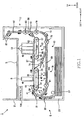
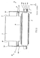
- the inkjet printer 1 constructed according to the first embodiment of the invention has a generally rectangular-parallelepiped- shaped housing body 2 including an upper portion that serves as a sheet exit tray 3.
- a sheet supplier 5 Within the housing body 2, there are disposed a sheet supplier 5, a first conveyor 7, a first recording head 9, a second conveyor 11, a set of second recording heads 13, a third conveyor 15, a sheet discharger 17 and a return conveyor 19.
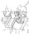
- a first supporter 93 see Fig. 4
- a posture changer 21 see Fig. 4
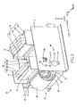
- a second supporter 119 see Fig. 3
- controller 100 a controller 100.
- the third conveyor 15 is configured to further convey the sheet conveyed by the first conveyor 7, in a third conveyance direction along a third conveyance path which is defined by the third conveyor 15 and which is other than the second conveyance path.
- the sheet discharger 17 is configured to discharge the sheet conveyed by the second conveyor 11 or third conveyor 15, toward the sheet exit tray 3.
- the return conveyor 19 is configured to convey or return the sheet (conveyed by the sheet discharger 17 in an opposite direction opposite to a discharging direction) to the first conveyor 7.
- the first supporter 93 is provided to support the first conveyor 7 and the first recording head 9 (see Fig. 4 ).
- the posture changer 21 is configured to change an angular postures of the first conveyor 7 and the first recording head 9, by causing the first supporter 93 to be pivoted (see Fig.
- the second supporter 119 is provided to support the second conveyor 11 and the second recording heads 13 (see Fig. 3 ).
- the controller 100 is configured to control activations of some of the these components, i.e., the sheet supplier 5, first conveyor 7, first recording head 9, second conveyor 11, second recording heads 13, third conveyor 15, sheet discharger 17, return conveyor 19 and posture changer 21. Each of these components of the inkjet printer 1 will be described below in detail.
- a main frame 4 is disposed within the housing body 2.
- the main frame 4 is constituted by a pair of plates consisting of a front-side plate and a rear-side plate.
- the main frame 4 supports the above-described components, i.e., the sheet supplier 5, first conveyor 7, first recording head 9, second conveyor 11, second recording heads 13, third conveyor 15, sheet discharger 17, return conveyor 19, first supporter 93, posture changer 21 and second supporter 119.
- Each of the plates of the main frame 4 has a through-hole 94 in which a shaft of a belt pulley 33 is to be introduced.
- Each of the plates of the main frame 4 further has through-holes (not shown) in which shafts of respective belt pulleys 55, 57 are introduced.
- the sheet supplying roller 27 is disposed in an upper portion of the sheet supplying cassette 23, and is rotatably held by the main frame 4.
- the sheet supplying roller 27 is arranged to be in contact with an uppermost one of the sheets accommodated in the sheet supplying cassette 23.
- the sheet supplying roller 27 is to be rotated by a motor (not shown) when the motor receives, from the controller 100, a command requesting of rotation of the sheet supplying roller 27. With rotation of the sheet supplying roller 27 that is contact with the uppermost sheet, the uppermost sheet is supplied to the conveying guide 29.
- the pair of conveying rollers 31 are disposed on halfway of the conveying guide 29, and are rotatably held by the main frame 4.
- One of the conveying rollers 31 is a drive roller that is to be rotated by a motor (not shown) when the motor receives, from the controller 100, a command requesting rotation of the drive roller.
- the other of the conveying rollers 31 is a driven roller that is to be rotated together with rotation of the drive roller.
- the pair of conveying rollers 31 serve to convey the sheet that is being guided by the conveying guide 29, toward the first conveyor 7.
- the walls 105, 106 are plate-like members extending and interconnecting the walls 103, 104.
- the first recording head 9 is sandwiched by the walls 105, 106 from the left and right sides.
- the belt pulleys 33, 35 are arranged in a right-left direction, and extend in a front-rear direction.
- the belt pulley 33 which is a left-side one of the belt pulleys 33, 35, is a drive pulley that is to be rotated by a motor (not shown) when the motor receives, from the controller 100, a command requesting of rotation of the belt pulley 33.
- the belt pulley 35 which is a right-side one of the belt pulleys 33, 35, is a driven pulley. That is, the driven pulley is provided by an upstream-side one, as viewed in the first conveyance direction, of the belt pulleys 33, 35.
- the shaft of the belt pulley 33 is connected to ground.
- the belt pulley 33 is rotated by a driving force of the motor, in clockwise direction as seen in Fig. 1 .
- the belt pulley 35 is rotated by rotation of the belt pulley 33 which is transmitted thereto via the conveyor belt 37, in the clockwise direction as seen in Fig. 1 .
- the shaft of the belt pulley 33 is rotatably introduced in the through-holes 120 that are formed in the walls 103, 104 of the first supporter 93.
- the shaft of the belt pulley 33 is rotatably introduced in the through-hole 94 that is formed in the main frame 4.
- the shaft of the belt pulley 35 is rotatably introduced in the through-holes 121 that are formed in the walls 103, 104 of the first supporter 93.
- the first recording head 9 is to be activated, when the first recording head 9 receives, from the controller 100, a command requesting of activation of the head 9, for thereby ejecting ink toward the sheet that is being conveyed by the first conveyor 7.
- the first recording head 9 is a black recording head that is configured to eject black ink toward the sheet.
- the first recording head 9 is a generally rectangular-parallelepiped-shaped head, as shown in Fig. 3 , and is configured to eject the black ink having supplied from a black ink tank (not shown) storing the black ink, toward the sheet through a plurality of nozzles that open in a nozzle opening surface (i.e., ejection surface) 45 of the head 9. As shown in Fig. 1 , the nozzle opening surface 45 constitutes a bottom surface of the head 9.
- the first recording head 9 is supported by the first supporter 93 such that the nozzle opening surface 45 of the head 9 and the supporting surface 38 of the conveyor belt 37 are opposed to each other with a predetermined distance therebetween.
- the first recording head 9 has a front surface 47 and a rear surface 49, and the front and rear surfaces 47, 49 have first projecting portions 51, 53, respectively, which extend outwardly.
- the first projecting portions 51, 53 are fixed to the above-described supporting projections 107, 108 of the first supporter 93, respectively, whereby the first recording head 9 is supported by the first supporter 93.
- Second Supporter 119 >
- the second supporter 119 supports the second conveyor 11 and the set of second recording heads 13.
- Each of the walls 122, 123 has through-holes (not shown) in which shafts of the respective belt pulleys 55, 57 are introduced.
- the shaft of the respective belt pulleys 55, 57 are rotatably introduced in the through-holes (not shown) of the walls 122, 123 and through-holes (not shown) of the main frame 4.
- supporting projections are provided in the respective walls 122, 123, and project inwardly from the respective walls 122, 123.
- the supporting projections cooperate to support the set of second recording heads 13.
- the walls 124, 125 are plate-like members extending and interconnecting the walls 122, 123.
- the second recording heads 13 are sandwiched by the walls 124, 125 from the left and right sides.
- the second conveyor 11 is configured to convey the sheet (conveyed by the first conveyor 7 when the first conveyor 7 takes the first angular posture) further in the rightward direction as seen in Fig. 1 .
- the sheet, which is conveyed by the first conveyor 7 and the second conveyor 11, is moved along bold arrows (black arrows) in Fig. 1 .
- the second conveyor 11 is constituted by the single belt conveyor unit 12.
- the belt conveyor unit 12 includes, in addition to the above-described belt pulleys 55, 57, a conveyor belt 59, a platen 63 and a second charge roller (not shown).
- the belt conveyor unit 12 is held by the main frame 4 via the second supporter 119.
- the belt pulleys 55, 57 are arranged in the right-left direction, and extend in the front-rear direction.
- the belt pulleys 55, 57 are both positioned in the same height position as the belt pulley 33. That is, the height positions of the respective belt pulleys 55, 57 are same to each other, and are same to the height position of the belt pulley 33.
- the belt pulley 55, which is a left-side one of the belt pulleys 55, 57, is a drive pulley that is to be rotated by a motor (not shown) when the motor receives, from the controller 100, a command requesting of rotation of the belt pulley 55.
- the belt pulley 57 which is a right-side one of the belt pulleys 55, 57, is a driven pulley.
- the shaft of the belt pulley 55 is connected to ground.
- the belt pulley 55 is rotated by a driving force of the motor, in clockwise direction as seen in Fig. 1 .
- the shafts of the respective belt pulleys 55, 57 are introduced in through-holes of the walls 122, 123 of the second supporter 119 and also in through-holes of the main frame 4.
- the platen 63 is fixed to the second supporter 119, and is disposed to be in contact with an upper portion of an inner circumferential surface of the conveyor belt 59, so as to support the conveyor belt 59. Owing to the platen 63, the supporting surface 60 of the conveyor belt 59 keeps a flat shape.
- the second charge roller (not shown) has substantially the same construction as the first charge roller 41.
- the second charge roller is disposed in proximity with the belt pulley 55, and is held in contact with the outer circumferential surface of the conveyor belt 59.
- the second charge roller is rotatably supported by the second supporter 119.
- the second charge roller includes a shaft (about which the second charge roller is to be rotated) that is made of a metallic material, and an outer peripheral portion that is made of an elastic material having insulating properties or semi-conducting properties.
- the shaft of the second charge roller is connected to a positive pole of a second direct-current source (not shown) that is to be activated when the second direct-current source receives, from the controller 100, a command requesting of activation of the second direct-current source.
- a negative pole of the second direct-current source is connected to ground.
- the conveyor belt 59 When a predetermined level of electric voltage is applied to the shaft of the second direct-current source, an electrical discharge is generated between the second charge roller and the conveyor belt 59. By the electrical discharge from the second charge roller, the conveyor belt 59 is charged with a positive charge. When the sheet is conveyed from the conveying guide 67 to the conveyor belt 59, the sheet is attracted onto the conveyor belt 59. Thus, by circulating the conveyor belt 59 to which the sheet is attracted, the sheet is conveyed along the second conveyance path that is defined by the supporting surface 60 of the conveyor belt 59, in the rightward direction as seen in Fig. 1 .
- the belt pulley 55, second charge roller and second direct-current source cooperate to constitute another attraction generating device that is configured to cause the sheet to be attracted to the conveyor belt 59.
- the second recording heads 13 are to be activated, when the second recording heads 13 receive, from the controller 100, a command requesting of activation of the heads 13, for thereby ejecting inks toward the sheet that is being conveyed by the second conveyor 11.
- the second recording heads 13 consist of three color recording heads that are configured to eject magenta, cyan and yellow inks toward the sheet.
- Each of the second recording heads 13 is a generally rectangular-parallelepiped-shaped head, as shown in Fig.
- the conveying guide 71 is fixed to the main frame 4, and extends in a right downward direction.
- the conveying guide 71 is aligned with the supporting surface 38 of the conveyor belt 37 of the first conveyor 7 when the first conveyor 7 takes the second angular posture.
- the conveying guide 71 serves to guide the sheet (conveyed by the first conveyor 7 when the first conveyor 7 takes the second angular posture) further in the right downward direction.
- the spur roller 75 is disposed on halfway of the conveying guide 71, and has a sharp-toothed surface as its outer circumferential surface.
- the spur roller 75 is rotatably held by the main frame 4. Even if the sheet (that is conveyed by the first conveyor 7 when the first conveyor 7 takes the second angular posture) is brought into contact at its leading end portion with the spur roller 75, the conveyance of the sheet is not impeded by resistance applied to the sheet, because the resistance is reduced by rotation of the spur roller 75.
- the pairs of conveying rollers 77, 78, 79 are rotatably held by the main frame 4, and are disposed on halfway of the conveying guide 73.
- One of each of the pairs of conveying rollers 77, 78, 79 is a drive roller that is to be rotated by a motor (not shown) when the motor receives, from the controller 100, a command requesting of rotation of the drive roller.
- the other of each of the pairs of conveying rollers 77, 78, 79 is a driven roller that is to be rotated by rotation of the drive roller.
- the pairs of conveying rollers 77, 78, 79 serve to convey the sheet (that is being guided by the conveying guide 73) toward the sheet discharger 17.
- the sheet discharger 17 is configured to discharge the sheet (conveyed by the second conveyor 11 or the third conveyor 15) toward the sheet exit tray 3.
- the sheet discharger 17 includes a conveying guide 81 and pairs of conveying rollers 85, 87.
- the pairs of conveying rollers 85, 87 are rotatably held by the main frame 4, and are disposed on halfway of the conveying guide 81.
- One of each of the pairs of conveying rollers 85, 87 is a drive roller that is to be rotated by a motor (not shown) when the motor receives, from the controller 100, a command requesting of rotation of the drive roller.
- the other of each of the pairs of conveying rollers 85, 87 is a driven roller that is to be rotated by rotation of the drive roller.
- the pair of conveying roller 85 which are disposed on a lower side of the pair of conveying rollers 87, serve to convey the sheet (that is being guided by the conveying guide 81) upwardly toward the pair of conveying rollers 87.
- a sheet sensor 88 is disposed in vicinity of the pair of conveying rollers 85.
- the sheet sensor 88 is configured to detect the sheet conveyed from the second conveyor 11 or the third conveyor 15, and to supply, to the controller 100, a signal indicative of detection of the sheet.
- the pair of conveying rollers 87 which are disposed on an upper side of the pair of conveying rollers 85, are rotated in forward directions, when the sheet is to be discharged to the sheet exit tray 3, for thereby discharging the sheet (that has been guided by the conveying guide 81) to the sheet exit tray 3.
- the pair of conveying rollers 87 are first rotated in the above-described forward directions, and then rotated in reverse directions opposite to the forward directions with a trailing end portion of the sheet being nipped by the pair of conveying rollers 85 (disposed in vicinity of the sheet sensor 88), for thereby conveying the sheet to the return conveyor 19.
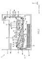
- the return conveyor 19 is configured to convey the sheet from the sheet discharger 17 back to the first conveyor 7, along bold arrows (hatched arrows) in Figs. 1 and 2 .
- the return conveyor 19 includes conveying guides 73, 89 and pairs of conveying rollers 78, 79, 91. It is noted that the conveying guide 73 and the pairs of conveying rollers 78, 79 are common to the return conveyor 19 and the third conveyor 15.
- the conveying guide 73 serves to guide the sheet (conveyed by the above-described opposite rotations of the pair of conveying rollers 87) to be moved in a left downward direction.
- the conveying guide 89 is fixed to the main frame 4, and includes a leftwardly extending portion and an upwardly extending portion extending from the leftwardly extending portion.
- the leftwardly extending portion extends leftwardly from a junction of the conveying guides 71, 73.
- the upwardly extending portion extends curvedly in an upward direction, and reaches the conveying guide 29.
- the upwardly extending portion of the conveying guide 89 is connected to a portion of the conveying guide 29 which is located below the pair of conveying rollers 31.
- the conveying guide 89 serves to guide the sheet (that has been guided by the conveying guide 73 by the rotations of the conveying rollers 87 in the reverse directions) toward the conveying guide 29.
- the pair of conveying rollers 78, 79 serve to convey the sheet (that is conveyed by the rotations of the conveying rollers 87 in the reverse directions) toward the conveying guide 88.
- the posture changer 21 is configured to change the angular posture of each of the first conveyor 7 and the first recording head 9, by pivoting the first supporter 93. As shown in Fig. 4 , the posture changer 21 includes the above-described forcing portion 101 and a drive mechanism 95 configured to pivot the first supporter 93.
- the forcing portion 101 is constituted by a spring that is interposed between the contact portion 99 of the first supporter 93 and the support plate 109 that is formed integrally with the main frame 4. A lower end portion of the spring is fixed to the contact portion 99 while an upper end portion of the spring is fixed to the support plate 109.
- the spring has a length which is larger than a distance between the support plate 109 and the contact portion 99. More specifically, the spring has a natural length which is larger than the distance between the support plate 109 and the contact portion 99 not only when the first conveyor 7 takes the first angular posture but also when the first conveyor 7 takes the second angular posture. Thus, the spring is being compressed while being interposed between the support plate 109 and the contact portion 99.
- the forcing portion 101 is configured to force the contact portion 99 in a downward direction. With the contact portion 99 being forced downwardly by the forcing portion 101, the first supporter 93 can be reliably pivoted by rotation of the eccentric cam 111.
- the drive mechanism 95 includes, in addition to the eccentric cam 111, a motor 114 and three gears 115, 116, 117.
- the eccentric cam 111 is rotatably held by the main frame 4, and is rotatable about a center of rotation which is offset from a gravitational center or a geometric center of the eccentric cam 111.
- the center of rotation of the eccentric cam 111 is located on a right side of the axis of the belt pulley 33.
- the eccentric cam 111 has an outer circumferential surface serving as a cam surface, and an upper portion of the outer circumferential surface of the cam 111 is held in contact with a lower surface 102 of the contact portion 99.
- the angular postures of the first conveyor 7 and the first recording head 9 are changed.
- the supporting surface 38 of the conveyor belt 37 is made substantially flush with the supporting surface 60 of the conveyor belt 59. That is, when the first conveyor 7 takes the first angular posture, the first conveyance path is directed to the second conveyance path defined by the second conveyor 11, such that the first conveyance path is aligned with the second conveyance path without a step between the first and second conveyance paths.
- the first conveyor 7 takes the second angular position
- the supporting surface 38 of the conveyor belt 37 is made substantially flush with the conveying guide 72.
- the first conveyance path is directed to the third conveyance path defined by the third conveyor 15, such that the first conveyance path is aligned with the third conveyance path without a step between the first and third conveyance paths.
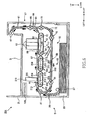
- the controller 100 When the controller 100 receives, from PC (personal computer), recording data representing color images that are to be recorded onto both-side faces of a sheet, the controller 100 controls the drive mechanism 95 such that the first conveyor 7 takes the first angular posture as shown in Fig. 1 .
- PC personal computer
- the controller 100 controls the sheet supplying roller 27 and the pair of conveying rollers 31 such that the sheet is conveyed from the sheet supplying cassette 23 to the first conveyor 7 via the conveying guide 29.
- the controller 100 controls the first conveyor 7 such that the sheet is conveyed in a rightward direction while being attracted to the conveyor belt 37. More precisely described, the controller 100 controls the first conveyor 7 such that the attraction generating device causes, even before the sheet reaches the conveyor belt 37, the outer circumferential surface of the conveyor belt 37 to have an attraction force by which the sheet is attracted onto the outer circumferential surface of the conveyor belt 37. In this instance, since the first conveyor 7 takes the first angular posture, the supporting surface 38 of the conveyor belt 37 is parallel to a horizontal plane, so that the sheet conveyed by the conveyor belt 37 is moved along the horizontal plane in the rightward direction.
- the sheet sensor 44 supplies, to the controller 100, a signal indicative of detection of the sheet by the sheet sensor 44.
- the controller 100 controls the first recording head 9 such that ink is ejected from the first recording head 9 when the sheet passes a region that is opposed to the first recording head 9, namely, when a given length of time has passed from the detection of the leading end portion of the sheet by the sheet sensor 44.
- the controller 100 controls the second conveyor 11, such that the sheet (conveyed to the second conveyor 11 via the conveying guide 67) is conveyed by the second conveyor 11 in the rightward direction while being attracted to the conveyor belt 59.
- the controller 100 controls the second recording heads 13 such that inks are ejected from the second recording heads 13 when the sheet passes a region that is opposed to the second recording heads 13, namely, when a given length of time has passed from the detection of the leading end portion of the sheet by the sheet sensor 44.
- the sheet is opposed to the nozzle opening surfaces 45, 69 of the first and second recording heads 9, 13 while being conveyed by the first and second conveyors 7, 11, and color image is recorded in a desired portion of a top surface of the sheet.
- the controller 100 controls the pairs of conveying rollers 85, 87 such that the sheet (conveyed by the conveyor belt 59) is conveyed toward the sheet exit tray 3 via the conveying guide 81.
- the sheet sensor 88 supplies, to the controller 100, a signal indicative of detection of the trailing end portion of the sheet by the sheet sensor 88.
- the controller 100 controls the pair of conveying rollers 87 such that directions of the rotations of the conveying rollers 87 are switched from the forward directions to the reverse directions.
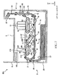
- the controller 100 controls the drive mechanism 95 such that the first conveyor 7 takes the second angular posture as shown in Fig. 2 .
- the controller 100 controls the sheet supplying roller 27 and the pair of conveying rollers 31 such that the sheet is conveyed from the sheet supplying cassette 23 to the first conveyor 7 via the conveying guide 29.
- the controller 100 controls the first conveyor 7 such that the sheet is conveyed in a rightward direction while being attracted to the conveyor belt 37.
- the supporting surface 38 of the conveyor belt 37 is inclined with respect to a horizontal plane, so that the sheet conveyed by the conveyor belt 37 is moved in a right downward direction.
- the controller 100 controls the first recording head 9 such that ink is ejected from the first recording head 9 when the sheet passes a region that is opposed to the first recording head 9, namely, when a given length of time has passed from the detection of the leading end portion of the sheet by the sheet sensor 44.
- the controller 100 controls the pairs of conveying rollers 78, 79, 85, 87 such that the sheet (conveyed by the first conveyor 7) is conveyed by the third conveyor 15 toward the sheet exit tray 3.
- the sheet is opposed to the nozzle opening surface 45 of the first recording head 9, while being conveyed by the first conveyor 7, and monochrome image is recorded in a desired portion of a top surface of the sheet.
- the controller 100 controls the pair of conveying rollers 87 such that directions of the rotations of the conveying rollers 87 are switched from the forward directions to the reverse directions.
- the controller 100 controls the first conveyor 7, first recording head 9 and third conveyor 15 in a same manner as when the monochrome image has been recorded on the top face of the sheet, such that a desired monochrome image is recorded on the bottom face of the sheet. Then, the controller 100 controls the pairs of conveying rollers 78, 79, 85, 87 such that the sheet having the images recoded on its top and bottom faces is discharged to the sheet exit tray 3. Thus, the both-side monochrome recording is completed.
- the sheet is conveyed by the third conveyor 15 in place of the second conveyor 11. That is, during the both-side monochrome recording, the sheet is conveyed along the third conveyance path which is defined by the third conveyor 15 and which is other than the second conveyance path defined by the second conveyor 11. Therefore, it is possible to restrain foreign substances such as paper dust from adhering onto the nozzle opening surfaces 69 of the second recording heads 13 which are opposed to the conveyor belt 59 of the second conveyor 11.
- the first conveyor 7 takes the first angular posture as shown in Fig. 1 , the supporting surfaces 38, 60 of the conveyor belts 37, 59 are substantially flush with each other, so that a conveyance path interconnecting the first and second conveyors 7, 11 (i.e., interconnecting the first and second conveyance paths) is not substantially bent or curved.
- the sheet can be conveyed from the first conveyor 7 to the second conveyor 11, without the sheet receiving a large convey resistance, which is a force applied to the sheet and acting in a direction opposite to the conveyance direction. Since a large convey resistance is not applied to the sheet, a velocity of the conveyed sheet is not momentarily reduced by a large amount. Therefore, even if the recording is being carried out by the first recording head 9 when the sheet is conveyed from the first conveyor 7 to the second conveyor 11, it is possible to avoid deterioration of quality of the recoded image, which could be caused if the velocity of the conveyed sheet were momentarily reduced by a large amount.
- the conveyor belt 37 attracts the sheet thereto while conveying the sheet, the sheet is attracted onto the supporting surface 38 of the conveyor belt 37, so that the sheet can be reliably conveyed by the conveyor belt 37, although the supporting surface 38 of the conveyor belt 37 constitutes a downslope surface, i.e., a slope surface that is inclined such that the slope surface has a height that is reduced in the first conveyance direction. Further, since the sheet is conveyed from the first conveyor 7 to the third conveyor 11 without receiving a large convey resistance, the velocity of the conveyed sheet is not momentarily reduced by a large amount.
- an increase of the size of the apparatus can be prevented, an amount of ink consumption can be reduced, and a reduction of the recorded image quality can be prevented.
- the first supporter 93 is pivotable about the axis of the belt pulley 33, so that a position of the belt pulley 33 is not changed irrespective of whether the first conveyor 7 takes the first angular posture or second angular posture. Therefore, irrespective of the angular posture of the first conveyor 7, the sheet (conveyed by the sheet supplier 5) can be stably conveyed by the conveyor belt 37 after having reached the conveyor belt 37.
- the first conveyor 7 includes a single conveyor unit in the form of the belt conveyor unit 6 that is configured to cause a sheet to be attracted onto the supporting surface 38 of the conveyor belt 37 and to convey the sheet.
- the first conveyor 7 may include, in place of the belt conveyor unit 6, pairs of conveying rollers and a platen for supporting a sheet, wherein the pairs of conveying rollers are disposed on upstream and downstream sides of the first recording head 9, and wherein the platen is disposed to be opposed to the nozzle opening surface 45 of the first recording head 9.
- the first conveyor 8 may include an attraction generating device that is provided for the platen, for causing a sheet to be attracted onto a supporting surface of the platen.
- the attraction generating device it is possible to employ a pair of comb-teeth-like electrodes as disclosed, for example, in JP-H07-330185A .
- the comb-teeth-like electrodes are spaced apart from each other by a given distance, for avoiding a short connection between the electrodes.
- Each of the comb-teeth-like electrodes has a plurality of elongated portions which are elongated in the right-left direction and which are arranged in the front-rear direction.
- the second conveyor 11 includes a single conveyor unit in the form of the belt conveyor unit 12 that is configured to cause a sheet to be attracted onto the supporting surface 60 of the conveyor belt 59 and to convey the sheet.
- the second conveyor 11 may include, in place of the belt conveyor unit 12, pairs of conveying rollers and a platen for supporting a sheet, wherein the pairs of conveying rollers are disposed on upstream and downstream sides of the set of second recording heads 13, and wherein the platen is disposed to be opposed to the nozzle opening surfaces 69 of the respective second recording heads 13.
- the second conveyor 11 may not include an attraction generating device configured to cause a sheet to be attracted onto a supporting surface of the platen.
- the belt conveyor unit 6 includes the attraction generating device which is constituted by the belt pulley 33, first charge roller 41 and first direct-current source 43 and which is configured to provide the conveyor belt 37 with the attraction force that is generated based on a static electricity.
- the belt conveyor unit 12 includes the attraction generating device which is constituted by the belt pulley 55, second charge roller and second direct-current source and which is configured to provide the conveyor belt 59 with the attraction force that is generated based on a static electricity.
- these arrangements are not essential.
- a pair of comb-teeth-like electrodes may be disposed on a surface of each of the platens 40, 63 which is in contact with a corresponding one of the conveyor belts 37, 59, wherein the comb-teeth-like electrodes are spaced apart from each other by a given distance, for avoiding a short connection between the electrodes.
- Each of the comb-teeth-like electrodes has a plurality of elongated portions which are elongated in the right-left direction and which are arranged in the front-rear direction.
- each of the conveyor belts 37, 59 is given the attraction force based on the static electricity, whereby a sheet is caused to be attracted onto a corresponding one of the supporting surfaces 38, 60.
- this arrangement is not essential.
- each of the conveyor belts 37, 59 may be constituted by a belt having self-bonding properties, so that a sheet can be attracted to the belt owing to the self-bonding properties.
- a sucking device may be provided for sucking air through holes that are formed through the conveyor belts 37, 59, for thereby enabling a sheet to be attracted to the conveyor belts 37, 59, owing to a sucking force that is generated by the sucking device.
- the third conveyor 15 may be located on an upper side of the first conveyor 7 or located in the same height position as the first conveyor 7.
- the second angular posture of the first conveyor 7 is an angular posture of the first conveyor 7 by which the first conveyance path (defined by the supporting surface 38 of the conveyor belt 37) is directed to the third conveyance path (defined by the conveying guides 71, 73). It is noted that, where the third conveyor 15 is located in the same height position as the first conveyor 7, the supporting surface 38 of the conveyor belt 37 is substantially flush with the conveying guides 71, 73.
- the first recording head 9 is a black recording head that is configured to eject black ink in a monochrome recording.
- the first recording head 9 may be a color recording head that is configured to eject color inks in a color recording.
- the first recording head 9 may be configured to eject liquid other than ink.
- Such a liquid may be a liquid that is to be ejected toward a sheet in a pre-recording operation that is to be carried out, prior to ejection of the ink, for the purpose of facilitating fixation of the ink onto the sheet or increasing color-developing properties of the ink.
- the set of second recording heads 13 consist of three color recording heads that are configured to eject magenta, cyan and yellow inks.
- the set of second recording heads 13 may consist of four or more recording heads including a recording head that is configured to eject the other color ink such as light magenta and light cyan inks.
- the second recording heads 13 may be a black recording head that is configured to eject black ink in a monochrome recording.
- the second recording heads 13 may be configured to eject liquid other than ink.
- the first supporter 93 is constructed to support the first conveyor 7 and the first recording head 9.
- the first supporter 93 may be constructed to support only the first conveyor 7, as long as the first recording head 9 is supported by another member.
- the angular posture of the first recording head 9 is changed such that the nozzle opening surface 45 of the first recording head 9 and the supporting surface 38 of the conveyor bet 37 are opposed to each other and are spaced apart from each other by a distance that is constant irrespective of change of the angular posture of the first conveyor 7.
- the posture changer 21 is constructed to cause the first conveyor 7 and the first recording head 9 to be pivoted by rotation of the eccentric cam 111.
- the posture changer 21 may be otherwise constructed, as long as it is capable of causing the first conveyor 7 and the first recording head 9 to be pivoted together with each other.
- the first supporter 93 may be provided with a rack that extends in a vertical direction while the drive mechanism 95 may be provided with a drive transmission mechanism and a pinion meshing with the rack, such that, for example, the first supporter 93 provided with the rack is pivotable, by rotation of the pinion, about the axis of the belt pulley 33.
- the posture changer 21 includes the forcing portion 101. However, the posture changer 21 may not include the forcing portion 101. Further, in the first embodiment, the upper portion of the eccentric cam 111 is held in contact with the lower surface 102 of the contact portion 99. However, the eccentric cam 111 and the contact portion 99 may be arranged such that a lower portion of the eccentric cam 111 is held in contact with an upper surface of the contact portion 99. In this modification, too, the contact portion 99 is forced by a forcing portion in a direction toward the eccentric cam 111.
- the controller 100 when the controller 100 receives recording data representing color images that are to be recorded onto both-side faces of a sheet, the controller 100 controls the drive mechanism 95 such that the first conveyor 7 takes the first angular posture. In this instance, the controller 100 may control the drive mechanism 95 such that the first conveyor 7 becomes to take the first angular posture before the sheet reaches the first conveyor 7. Further, in the above-described first embodiment, when the controller 100 receives recording data representing monochrome images that are to be recorded onto both-side faces of a sheet, the controller 100 controls the drive mechanism 95 such that the first conveyor 7 takes the second angular posture. In this instance, the controller 100 may control the drive mechanism 95 such that the first conveyor 7 becomes to take the second angular posture before the sheet reaches the first conveyor 7.
- the controller 100 may control the drive mechanism 95, such that the first conveyor 7 takes the first angular position for recording of the color image onto the one of the both-side faces of the sheet, and such that the first conveyor 7 takes the second angular position for recording of the monochrome image onto the other of the both-side faces of the sheet. That is, the controller 100 may control the drive mechanism 95 such that the first conveyor 7 takes the first angular posture when color-image is to be recoded onto a sheet, and such that the first conveyor 7 takes the second angular posture when monochrome-image is to be recoded onto a sheet.
- FIG. 6 and 7 there will be described an inkjet printer 201 that is constructed according to a second embodiment of the invention.
- the same reference numerals as used in the first embodiment will be used to identify the same or similar elements, and redundant description of these elements will not be provided.
- a first conveyor 203 has a construction different from that of the first conveyor 7 of the inkjet printer 1 of the first embodiment. Due to the difference of the first conveyor 203 from the first conveyor 7 of the inkjet printer 1 of the first embodiment, the first supporter 93 and the conveying guides 67, 71 in this second embodiment are slightly different from those in the first embodiment with respect to construction. However, the same reference numerals will be used for these elements since they are substantially the same as those in the first embodiment.
- the first supporter 93 supports a belt conveyor unit 204 that will be described later in detail. As in the first embodiment, the first supporter 93 is pivotable by the posture changer 21.
- the walls 103, 104 of the first supporter 93 have through-holes (not shown) in which shafts of respective belt pulleys 211, 212 are introduced.
- the shaft of the belt pulley 211 is introduced in the through-holes of the respective walls 103, 104 and also in a through-hole of the main frame 4, so that the first supporter 93 is pivotable about the axis of the belt pulley 211.
- the walls 105, 106 are plate-like members extending and interconnecting the walls 103, 104.
- the first recording head 9 is sandwiched by the walls 105, 106 from the left and right sides.
- the walls 105, 106 are not disposed in respective positions for sandwiching the first recording head 9.
- the first conveyor 203 is configured to convey the sheet (conveyed by the sheet supplier 5) in the rightward direction.
- the first conveyor 203 includes two belt conveyor units 202, 204 which are arranged in the right-left direction.
- the belt conveyor unit 202 includes belt pulleys 209, 210, a conveyor belt 205, a platen 215, a pressing roller 213 and a third charge roller (not shown). Since the belt conveyor unit 202 has a construction substantially the same as those of the belt conveyor units 6, 12 in the first embodiment, redundant description of the belt conveyor unit 202 will not be provided.
- the belt pulleys 209, 210 are both positioned in the same height position as the belt pulley 55.
- the belt conveyor unit 202 is held by the main frame 4, and is configured to convey the sheet (which is held on a supporting surface 206 constituted by an upper portion of an outer circumferential surface of the conveyor belt 205) in the rightward direction.
- the belt conveyor unit 204 includes belt pulleys 211, 212, a conveyor belt 207, a platen 217 and a fourth charge roller (not shown). Since the belt conveyor unit 204 has a construction substantially the same as those of the belt conveyor units 6, 12 in the first embodiment, redundant description of the belt conveyor unit 204 will not be provided.
- the belt conveyor unit 204 does not include a pressing roller that is to serve to press the sheet down onto the outer circumferential surface of the conveyor belt 207.
- the belt conveyor unit 204 is supported by the first supporter 93, like the belt conveyor unit 6 in the first embodiment.
- the shaft of the belt pulley 211 is introduced in the through-holes of the walls 103, 104 of the first supporter 93 and also in the through-hole of the main frame 4.
- the posture of the first conveyor 204 is changed between the first angular posture and the second angular posture.
- the angular posture of only the belt conveyor unit 204 which is a right-side one, i.e., downstream-side one of the two belt conveyor units 202, 204, is changeable between the first angular posture and the second angular posture. That is, in the second embodiment, the angular posture of the belt conveyor unit 204, which corresponds to a downstream-side portion of the first conveyor 203, is changeable, while the angular posture of the entirety of the first conveyor 7 is changeable in the above-described first embodiment.
- the belt pulley 212 is positioned in the same height position as the belt pulley 211, and a supporting surface 208 (which is an upper-side surface provided by an upper portion of the outer circumferential surface of the conveyor belt 207) is parallel to a horizontal plane.
- a supporting surface 208 which is an upper-side surface provided by an upper portion of the outer circumferential surface of the conveyor belt 207 is parallel to a horizontal plane.
- the sheet which is conveyed by the first conveyor 203, is moved in the rightward direction while being supported on the supporting surface 206 of the conveyor belt 205 and is then moved further in the rightward direction while being supported on the supporting surface 208 of the conveyor belt 207.
- the belt conveyor unit 204 takes the second angular posture as shown in Fig. 7 , the belt pulley 212 is positioned in a position lower than the belt pulley 211, and the supporting surface 208 of the conveyor belt 207 is inclined with respect to a horizontal plane, in a right downward direction.
- the sheet conveyed by the conveyor belt 207 is moved in the right downward direction, while being supported on the supporting surface 208 of the conveyor belt 207.
- the first conveyance path defined by the first conveyor 203 includes an upstream-side part defined by the supporting surface 206 of the conveyor belt 205 and a downstream-side part defined by the supporting surface 208 of the conveyor belt 207.
- the first recording head 219 is to be activated, when the first recording head 219 receives, from the controller 100, a command requesting of activation of the head 219, for thereby ejecting ink toward the sheet that is being conveyed by the conveyor belt 205 of the first conveyor 203.
- the first recording head 219 is fixed to the main frame 4 such that a nozzle opening surface (i.e., ejection surface) 220 of the first recording head 219 and the supporting surface 206 of the conveyor belt 205 are opposed to each other and spaced apart from each other by a predetermined distance.
- the first recording head 219, which is fixed to the main frame 4, has a fixed posture that is not changeable.
- the angular posture of the belt conveyor unit 204 as the downstream-side portion of the first conveyor 203, which applies a conveying force to the sheet while attracting the sheet thereto, is changed whereby the angular posture of the belt conveyor unit 204 is changed between the first angular posture and the second angular posture.
- the belt conveyor unit 204 takes the first angular posture as shown in Fig. 6 , the supporting surfaces 206, 208, 60 of the three conveyor belts 205, 207, 59 are substantially flush with each other, so that a conveyance path interconnecting the first and second conveyors 203, 11 (i.e., interconnecting the first and second conveyance paths) is not substantially bent or curved.
- the sheet can be conveyed from the first conveyor 203 to the second conveyor 11, without the sheet receiving a large convey resistance, which is a force applied to the sheet and acting in a direction opposite to the conveyance direction. Therefore, even if the recording is being carried out by the first recording head 219 when the sheet is conveyed from the first conveyor 203 to the second conveyor 11, it is possible to avoid deterioration of quality of the recoded image, which could be caused if the velocity of the conveyed sheet were momentarily reduced by a large amount.
- the supporting surface 208 of the conveyor belt 207 is inclined so as to extend in a right downward direction. Since the conveyor belt 207 attracts the sheet thereto while conveying the sheet, the sheet is attracted onto the supporting surface 208 of the conveyor belt 207, so that the sheet can be reliably conveyed by the conveyor belt 207, although the supporting surface 208 of the conveyor belt 207 constitutes a downslope surface, i.e., a slope surface that is inclined such that the slope surface has a height that is reduced in the first conveyance direction.
- the sheet when the sheet is transferred from the conveyor belt 205 to the conveyor belt 207, the sheet is caused to be attracted onto the supporting surface 208 of the conveyor belt 207 upon arrival of the leading end portion of the sheet at the conveyor belt 207, so that the direction of conveyance the sheet is changed by the attraction of the sheet onto the supporting surface 208 of the conveyor belt 207. Therefore, as compared with an arrangement in which the direction of conveyance of the sheet is changed by a pivotable flapper that does not apply a conveying force to the sheet, it is possible to reduce the conveyance resistance applied to the sheet.
- the conveyance direction is abruptly changed upon collision of the leading end of the sheet with the flapper, thereby resulting in a large convey resistance that is momentarily applied to the sheet.
- a large convey resistance is not applied to the sheet.
- the direction of conveyance of the sheet is changed by the attraction of the leading end portion of the sheet onto the supporting surface 208 of the conveyor belt 207. Consequently, as compared with an arrangement with the pivotable flapper, the convey resistance applied to the sheet can be made smaller. Accordingly, even if the recording is being continuously carried out by the first recording head 219 when the sheet is conveyed from the first conveyor 203 to the second conveyor 11, it is possible to avoid deterioration of quality of the recoded image.
- the first conveyor 203 includes two conveyor units in the form of the belt conveyor units 202, 204.
- the first conveyor 203 may include, in place of the belt conveyor units 202, 204, pairs of conveying rollers and a platen for supporting a sheet.
- the conveyor belt 205 is configured to convey a sheet while causing the sheet to be attracted onto the supporting surface 206 of the conveyor belt 205.
- this arrangement is not essential.
- the belt conveyor units 202, 204 include attraction generating devices which are constituted by the belt pulleys 209, 211, first and second charge rollers and first and second direct-current sources and which are configured to provide the conveyor belts 205, 207 with the attraction forces each of which is generated based on a static electricity.
- this arrangements is not essential.
- a pair of comb-teeth-like electrodes may be disposed on a surface of each of the platens 215, 217 which is in contact with a corresponding one of the conveyor belts 205, 207, wherein the comb-teeth-like electrodes are spaced apart from each other by a given distance, for avoiding a short connection between the electrodes.
- Each of the comb-teeth-like electrodes has a plurality of elongated portions which are elongated in the right-left direction and which are arranged in the front-rear direction.
- an attraction force based on a static electricity can be generated in the conveyor belts 205, 207.
- each of the conveyor belts 205, 207 is given the attraction force based on the static electricity, whereby a sheet is caused to be attracted onto a corresponding one of the supporting surfaces 206, 208.
- this arrangement is not essential.
- each of the conveyor belts 205, 207 may be constituted by a belt having self-bonding properties, so that a sheet can be attracted to the belt owing to the self-bonding properties.
- a sucking device may be provided for sucking air through holes that are formed through the conveyor belts 205, 207, for thereby enabling a sheet to be attracted to the conveyor belts 205, 207, owing to a sucking force that is generated by the sucking device.
- the conveyor belts 205, 207 are stretched around the belt pulleys 209, 210, 211, 212, and the upstream-side belt pulleys 209, 211 serve as drive rollers.
- the downstream-side belt pulleys 210, 212, in place of the upstream-side belt pulleys 209, 211, may serve as drive rollers.
- a pressing roller serving to press a sheet onto the outer circumferential surface of the conveyor belt 207.
- a freely rotatable roller may be provided as such a pressing roller.
- the sheet, which has been transferred from the conveyor belt 205 to the conveyor belt 207 is likely to collide at its leading end portion with the pressing roller, it is possible to restrain the convey resistance applied to the sheet because the pressing roller is constituted by a freely rotatable roller.
- the second conveyor 11 may be located either on an upper side or a lower side of the conveyor belt 207.
- the first angular posture of the first conveyor 7 is an angular posture of the conveyor belt 207 by which the first conveyance path (defined by the supporting surfaces 206, 208 of the respective conveyor belts 205, 207) is directed to the second conveyance path (defined by the supporting surface 60 of the conveyor belt 59).
- the third conveyor 15 is located on a lower side of the conveyor belt 207.
- the third conveyor 15 may be located on an upper side of the conveyor belt 207 or located in the same height position as the conveyor belt 207.
- the second angular posture of the conveyor belt 207 is an angular posture of the conveyor belt 207 by which the first conveyance path (defined by the supporting surfaces 206, 208 of the respective conveyor belts 205, 207) is directed to the third conveyance path (defined by the conveying guides 71, 73). It is noted that, where the third conveyor 15 is located in the same height position as the conveyor belt 207, the supporting surface 208 of the conveyor belt 207 is substantially flush with the conveying guides 71, 73.
Landscapes
- Engineering & Computer Science (AREA)
- Mechanical Engineering (AREA)
- Ink Jet (AREA)
- Handling Of Sheets (AREA)
- Handling Of Cut Paper (AREA)
- Separation, Sorting, Adjustment, Or Bending Of Sheets To Be Conveyed (AREA)
Claims (13)
- Bildaufzeichnungsvorrichtung (1; 201), aufweisend:einen erster Förderer (7; 203), der so konfiguriert ist, dass er ein Aufzeichnungsmedium entlang eines ersten Förderpfads, der von dem ersten Förderer definiert wird, befördert;einen ersten Aufzeichnungskopf (9; 219), der so konfiguriert ist, dass er Flüssigkeit in Richtung des Aufzeichnungsmediums, das von dem ersten Förderer befördert wird, ausstößt;einen zweiten Förderer (11), der so konfiguriert ist, dass er das Aufzeichnungsmedium, das von dem ersten Förderer befördert wird, entlang eines zweiten Förderpfads, der von dem zweiten Förderer definiert wird, befördert;einen zweiten Aufzeichnungskopf (13), der so konfiguriert ist, dass er Flüssigkeit in Richtung des Aufzeichnungsmediums, das von dem zweiten Förderer befördert wird, ausstößt;einen dritten Förderer (15), der so konfiguriert ist, dass er das Aufzeichnungsmedium, das von dem ersten Förderer befördert wird, entlang eines dritten Förderpfads, der von dem dritten Förderer definiert wird, befördert, und der sich von dem zweiten Förderpfad unterscheidet; und gekennzeichnet durcheinen Stellungswechsler (21), der so konfiguriert ist, dass er eine Stellung von zumindest einem stromabwärtsseitigen Abschnitt (7; 204) des ersten Förderers (7; 203) wechselt, wobei der zumindest stromabwärtsseitige Abschnitt des ersten Förderers veranlasst wird, eine ausgewählte von einer Mehrzahl an schrägen Stellungen einzunehmen, einschließlich einer ersten schrägen Stellung und einer zweiten schrägen Stellung, sodass zumindest ein stromabwärtsseitiger Teil des ersten Förderpfads, der von dem zumindest stromabwärtsseitigen Abschnitt des ersten Förderers definiert wird, zu dem zweiten Förderpfad gerichtet ist, wenn der zumindest stromabwärtsseitige Teil des ersten Förderers die erste schräge Stellung einnimmt, und so, dass der zumindest stromabwärtsseitige Teil des ersten Förderpfads zu dem dritten Förderpfad gerichtet ist, wenn der zumindest stromabwärtsseitige Teil des ersten Förderers die zweite schräge Stellung einnimmt.
- Bildaufzeichnungsvorrichtung (1; 201) nach Anspruch 1, wobei der zumindest stromabwärtsseitige Teil des ersten Förderpfads mit dem zweiten Förderpfad ausgerichtet ist, wenn der zumindest stromabwärtsseitige Teil (7; 204) des ersten Förderers (7; 203) die erste schräge Stellung einnimmt,
und wobei der zumindest stromabwärtsseitige Teil des ersten Förderpfads mit dem dritten Förderpfad ausgerichtet ist, wenn der zumindest stromabwärtsseitige Teil des ersten Förderers die zweite schräge Stellung einnimmt. - Bildaufzeichnungsvorrichtung (1; 201) nach Anspruch 1 oder 2, wobei der zumindest stromabwärtsseitige Abschnitt (7; 204) des ersten Förderers (7; 203) so konfiguriert ist, dass er eine Förderkraft auf das Aufzeichnungsmedium ausübt, während er das Aufzeichnungsmedium dorthin anzieht.
- Bildaufzeichnungsvorrichtung (1; 201) nach Anspruch 3, wobei der zumindest stromabwärtsseitige Abschnitt (7; 204) des ersten Förderers (7; 203) ein Förderband (37; 207) beinhaltet, das eine Tragefläche (38; 208) aufweist, die von dem zumindest stromabwärtsseitigen Teil des ersten Förderpfads definiert wird, wobei der zumindest stromabwärtsseitige Abschnitt des ersten Förderers so konfiguriert ist, dass das Aufzeichnungsmedium befördert wird, das veranlasst wird, auf der Tragefläche zu haften,
und wobei die Tragefläche des Förderbands eine abschüssige Fläche darstellt, wenn der zumindest stromabwärtsseitige Abschnitt des ersten Förderers die erste schräge Stellung einnimmt und/oder wenn der zumindest stromabwärtsseitige Abschnitt des ersten Förderers die zweite schräge Stellung einnimmt. - Bildaufzeichnungsvorrichtung (1; 201) nach einem der Ansprüche 1 bis 4, weiter aufweisend eine Stütze (93; 119), die den zumindest stromabwärtsseitigen Abschnitt (7; 204) des ersten Förderers (7; 203) stützt,
wobei der zumindest stromabwärtsseitige Abschnitt des ersten Förderers ein endloses Förderband (37; 207) beinhaltet, das das Aufzeichnungsmedium, das auf einer äußeren umlaufenden Fläche des endlosen Förderbands gehalten wird, tragen soll, und das zirkuliert werden soll um so das Aufzeichnungsmedium zu fördern,
und wobei der Stellungswechsler (21) so konfiguriert ist, dass er die Stellung des zumindest stromabwärtsseitigen Abschnitts (7; 204) des ersten Förderers (7; 203) wechselt, indem bewirkt wird, dass die Stütze um einen stromaufwärtsseitigen Abschnitt des endlosen Förderbands geschwenkt wird. - Bildaufzeichnungsvorrichtung (1; 201) nach Anspruch 5, wobei der zumindest stromabwärtsseitige Abschnitt (7; 204) des ersten Förderers (7; 203) des Weiteren eine Anziehungskraft-Erzeugungseinrichtung (33, 41, 43) beinhaltet, die so konfiguriert ist, dass sie das Aufzeichnungsmedium veranlasst, auf die äußere umlaufende Fläche des endlosen Förderbands (37; 207) gezogen zu werden.
- Bildaufzeichnungsvorrichtung (1; 201) nach Anspruch 5 oder 6, wobei der Stellungswechsler (21) einen Exzenternocken (111) beinhaltet, und
wobei die Stütze (93, 119) einen Berührungsabschnitt (99) beinhaltet, der mit dem Exzenternocken in Berührung gehalten wird, wobei die Stütze um den stromaufwärtsseitigen Abschnitt des endlosen Förderbands durch Drehung des Exzenternockens, der mit dem Berührungsabschnitt der Stütze in Berührung gehalten wird, schwenkbar ist. - Bildaufzeichnungsvorrichtung (1; 201) nach Anspruch 7, wobei sich der Berührungsabschnitt (99) über dem Exzenternocken (111) befindet und eine untere Fläche (102) aufweist, die mit einem oberen Abschnitt des Exzenternockens in Berührung gehalten wird.
- Bildaufzeichnungsvorrichtung (1; 201) nach Anspruch 7 oder 8, wobei der Stellungswechsler (21) einen Zwingabschnitt (101) beinhaltet, der den Berührungsabschnitt (99) in eine Richtung hin zu dem Exzenternocken (111) zwingt.
- Bildaufzeichnungsvorrichtung (1) nach einem der Ansprüche 1 bis 9, wobei der Stellungswechsler (21) so konfiguriert ist, dass er die Stellung einer Gesamtheit des ersten Förderers (7) ändert, wobei die Gesamtheit des ersten Förderers dazu gebracht wird, die ausgewählte aus der Mehrzahl an schrägen Stellungen, welche die erste schräge Stellung und die zweite schräge Stellung mit einschließen, einzunehmen, so dass eine Gesamtheit des ersten Förderpfads, der von der Gesamtheit des ersten Förderers definiert wird, auf den zweiten Förderpfad gerichtet ist, wenn die Gesamtheit des ersten Förderers die erste schräge Stellung einnimmt, und so, dass die Gesamtheit des ersten Förderpfads auf den dritten Förderpfad gerichtet ist, wenn die Gesamtheit des ersten Förderers die zweite schräge Stellung einnimmt.
- Bildaufzeichnungsvorrichtung (1) nach Anspruch 10, aufweisend eine Stütze (93), die die Gesamtheit des ersten Förderers (7) stützt,
wobei die Gesamtheit des ersten Förderers (7) ein Einzelband (37) aufweist, das aus einem endlosen Förderband (37) besteht, das das Aufzeichnungsmedium trägt, welches auf einer äußeren umlaufenden Fläche des endlosen Förderbands gehalten wird, und das zirkuliert werden kann, um damit das Aufzeichnungsmedium zu befördern,
wobei der Stellungswechsler (21) so konfiguriert ist, dass er die Stellung der Gesamtheit des ersten Förderers (7; 203) ändert, indem die Stütze dazu gebracht wird, um einen stromaufwärtsseitigen Abschnitt des endlosen Förderbands zu schwenken,
und wobei die Stütze den ersten Aufzeichnungskopf (9) und die Gesamtheit des ersten Förderers derart hält, dass eine Ausstoßfläche (45) des ersten Aufzeichnungskopfs (9) in einer Entfernung von der äußeren umlaufenden Fläche des endlosen Förderbands (37) entfernt ist, die unbeeinflusst durch den Wechsel der Stellung der Gesamtheit des ersten Förderers konstant ist. - Bildaufzeichnungsvorrichtung (201) nach einem der Ansprüche 1 bis 9, wobei der Stellungswechsler (21) so konfiguriert ist, dass er die Stellung des stromabwärtsseitigen Abschnitts (204) des ersten Förderers (203) ändert, wobei der stromabwärtsseitige Abschnitt des ersten Förderers dazu gebracht wird, die ausgewählte von der Mehrzahl an schrägen Stellungen, einschließlich der ersten schrägen Stellung und der zweiten schrägen Stellung, einzunehmen, sodass der stromabwärtsseitige Teil des ersten Förderpfads, der von dem stromabwärtsseitigen Abschnitt des ersten Förderers definiert wird, auf den zweiten Förderpfad gerichtet ist, wenn der stromabwärtsseitige Teil des ersten Förderers die erste schräge Stellung einnimmt, und sodass der stromabwärtsseitige Teil des ersten Förderpfads zu dem dritten Förderpfad gelenkt wird, wenn der stromabwärtsseitige Teil des ersten Förderers die zweite schräge Stellung einnimmt.
- Bildaufzeichnungsvorrichtung (201) nach Anspruch 12, wobei der stromabwärtsseitige Abschnitt (204) des ersten Förderers (203) ein Einzelband (207) aufweist, das aus einem endlosen Förderband (207) besteht,
und wobei der erste Förderer (203) einen stromaufwärtsseitigen Abschnitt beinhaltet, der sich auf einer stromaufwärtsseitigen Seite des stromabwärtsseitigen Abschnitts (204) befindet, wobei der stromaufwärtsseitige Abschnitt des ersten Förderers so konfiguriert ist, dass das Aufzeichnungsmedium befördert wird, während das Aufzeichnungsmedium dazu gebracht wird, dem ersten Aufzeichnungskopf (219) gegenüber zu liegen.
Applications Claiming Priority (1)
| Application Number | Priority Date | Filing Date | Title |
|---|---|---|---|
| JP2010150547A JP5577893B2 (ja) | 2010-06-30 | 2010-06-30 | 画像記録装置 |
Publications (3)
| Publication Number | Publication Date |
|---|---|
| EP2402166A2 EP2402166A2 (de) | 2012-01-04 |
| EP2402166A3 EP2402166A3 (de) | 2012-10-31 |
| EP2402166B1 true EP2402166B1 (de) | 2013-07-17 |
Family
ID=44476712
Family Applications (1)
| Application Number | Title | Priority Date | Filing Date |
|---|---|---|---|
| EP11002372.8A Not-in-force EP2402166B1 (de) | 2010-06-30 | 2011-03-22 | Bildaufzeichnungsvorrichtung |
Country Status (4)
| Country | Link |
|---|---|
| US (1) | US8523348B2 (de) |
| EP (1) | EP2402166B1 (de) |
| JP (1) | JP5577893B2 (de) |
| CN (1) | CN102310661B (de) |
Families Citing this family (8)
| Publication number | Priority date | Publication date | Assignee | Title |
|---|---|---|---|---|
| JP5625823B2 (ja) * | 2010-11-30 | 2014-11-19 | ブラザー工業株式会社 | 画像形成装置 |
| DE102012103712B4 (de) * | 2012-04-27 | 2015-10-15 | Böwe Systec Gmbh | Vorrichtung und Verfahren zum seriellen Bedrucken von Druckmedien |
| JP5703267B2 (ja) * | 2012-07-27 | 2015-04-15 | 京セラドキュメントソリューションズ株式会社 | インクジェット記録装置 |
| JP6691757B2 (ja) * | 2015-09-30 | 2020-05-13 | 理想科学工業株式会社 | インクジェット印刷装置 |
| JP6938287B2 (ja) * | 2017-09-06 | 2021-09-22 | キヤノン株式会社 | 画像形成装置 |
| JP7224808B2 (ja) * | 2018-08-10 | 2023-02-20 | キヤノン株式会社 | 記録装置、その制御方法、及びプログラム |
| DE102019110115B4 (de) * | 2019-04-17 | 2021-03-18 | Canon Production Printing Holding B.V. | Tintendruckgerät |
| JP7556749B2 (ja) * | 2020-11-02 | 2024-09-26 | 理想科学工業株式会社 | 搬送装置 |
Family Cites Families (28)
| Publication number | Priority date | Publication date | Assignee | Title |
|---|---|---|---|---|
| FR2541975B1 (fr) * | 1983-03-02 | 1990-05-04 | Canon Kk | Appareil d'enregitrement d'images multifonctions |
| US4591884A (en) * | 1983-03-10 | 1986-05-27 | Canon Kabushiki Kaisha | Multi-function image recording apparatus |
| US4748516A (en) * | 1985-03-15 | 1988-05-31 | Brother Kogyo Kabushiki Kaisha | Input/output device for image reading and printing |
| JPS63246754A (ja) * | 1987-04-01 | 1988-10-13 | Minolta Camera Co Ltd | 画像作成装置 |
| JP2816217B2 (ja) * | 1990-02-21 | 1998-10-27 | キヤノン株式会社 | 記録装置 |
| JP2804715B2 (ja) | 1994-06-13 | 1998-09-30 | キヤノン株式会社 | 記録装置 |
| JPH08258342A (ja) * | 1995-03-27 | 1996-10-08 | Oki Data:Kk | 記録装置及び記録方法 |
| JP2004070152A (ja) | 2002-08-08 | 2004-03-04 | Sharp Corp | カラー画像形成装置 |
| JP3873949B2 (ja) * | 2003-08-20 | 2007-01-31 | ブラザー工業株式会社 | インクジェットプリンタ |
| CN101045377B (zh) * | 2003-09-10 | 2010-06-23 | 精工爱普生株式会社 | 喷液装置 |
| JP4274180B2 (ja) * | 2004-02-16 | 2009-06-03 | セイコーエプソン株式会社 | インクジェット記録装置 |
| US7188929B2 (en) * | 2004-08-13 | 2007-03-13 | Xerox Corporation | Parallel printing architecture with containerized image marking engines |
| US7123873B2 (en) * | 2004-08-23 | 2006-10-17 | Xerox Corporation | Printing system with inverter disposed for media velocity buffering and registration |
| US7740348B2 (en) * | 2004-09-27 | 2010-06-22 | Seiko Epson Corporation | Liquid ejecting apparatus |
| US20070025794A1 (en) * | 2005-06-17 | 2007-02-01 | Kubin Dale K | A printer |
| JP4687287B2 (ja) * | 2005-07-05 | 2011-05-25 | 富士ゼロックス株式会社 | 液滴吐出装置 |
| JP4458012B2 (ja) * | 2005-09-28 | 2010-04-28 | ブラザー工業株式会社 | 画像記録装置 |
| JP2007237402A (ja) * | 2006-03-03 | 2007-09-20 | Fuji Xerox Co Ltd | 液滴吐出装置 |
| JP4305529B2 (ja) | 2007-03-01 | 2009-07-29 | ブラザー工業株式会社 | インクジェット記録装置 |
| EP1974939B1 (de) * | 2007-03-29 | 2012-12-26 | Brother Kogyo Kabushiki Kaisha | Bildaufzeichnungsvorrichtung mit Trennriemen |
| JP5130853B2 (ja) * | 2007-09-28 | 2013-01-30 | ブラザー工業株式会社 | 画像記録装置 |
| JP5098600B2 (ja) * | 2007-11-30 | 2012-12-12 | ブラザー工業株式会社 | 記録装置 |
| JP4968053B2 (ja) * | 2007-12-26 | 2012-07-04 | ブラザー工業株式会社 | 記録装置 |
| JP2009160778A (ja) * | 2007-12-28 | 2009-07-23 | Ricoh Co Ltd | 画像形成装置 |
| JP4954119B2 (ja) * | 2008-02-26 | 2012-06-13 | デュプロ精工株式会社 | 排紙装置 |
| JP4640478B2 (ja) * | 2008-09-26 | 2011-03-02 | ブラザー工業株式会社 | 画像記録装置 |
| JP4640479B2 (ja) * | 2008-09-26 | 2011-03-02 | ブラザー工業株式会社 | 画像記録装置 |
| JP5024354B2 (ja) * | 2009-11-04 | 2012-09-12 | ブラザー工業株式会社 | インクジェット記録装置 |
-
2010
- 2010-06-30 JP JP2010150547A patent/JP5577893B2/ja not_active Expired - Fee Related
-
2011
- 2011-03-17 CN CN201110070632.1A patent/CN102310661B/zh active Active
- 2011-03-22 EP EP11002372.8A patent/EP2402166B1/de not_active Not-in-force
- 2011-03-27 US US13/072,750 patent/US8523348B2/en not_active Expired - Fee Related
Also Published As
| Publication number | Publication date |
|---|---|
| JP2012011673A (ja) | 2012-01-19 |
| JP5577893B2 (ja) | 2014-08-27 |
| CN102310661B (zh) | 2014-03-26 |
| EP2402166A2 (de) | 2012-01-04 |
| CN102310661A (zh) | 2012-01-11 |
| US20120001992A1 (en) | 2012-01-05 |
| US8523348B2 (en) | 2013-09-03 |
| EP2402166A3 (de) | 2012-10-31 |
Similar Documents
| Publication | Publication Date | Title |
|---|---|---|
| EP2402166B1 (de) | Bildaufzeichnungsvorrichtung | |
| EP2319700B1 (de) | Tintenstrahlaufzeichnungsvorrichtung | |
| EP2168776B1 (de) | Bildaufzeichnungsvorrichtung | |
| JP4306756B2 (ja) | 画像記録装置 | |
| US8556256B2 (en) | Image forming apparatus having clutch assembly | |
| JP4905576B2 (ja) | 画像記録装置 | |
| JP4760941B2 (ja) | インクジェット記録装置 | |
| EP2481696B1 (de) | Aufzeichnungsvorrichtung | |
| US8186826B2 (en) | Inkjet recording apparatus | |
| US20080211863A1 (en) | Inkjet recording apparatus | |
| JP2010208095A (ja) | 記録剤収容容器及び画像形成装置 | |
| JP2012171766A (ja) | 画像形成装置 | |
| JP2012197176A (ja) | 画像形成装置 | |
| CN101357536A (zh) | 喷墨记录设备 | |
| US20090189946A1 (en) | Liquid ejecting apparatus | |
| JP5454360B2 (ja) | 記録装置 | |
| JP2005022318A (ja) | プラテン板及び液体吐出装置 | |
| JP2009196732A (ja) | 記録装置 | |
| JP2004338867A (ja) | 画像形成装置 | |
| JP2005022319A (ja) | 液体吐出装置 | |
| JP5062358B2 (ja) | インクジェット記録装置 | |
| JP2004231382A (ja) | 画像形成装置 | |
| JP2007161368A (ja) | 記録紙搬送装置、及び記録装置 | |
| JP2004009516A (ja) | インクジェットプリンタ | |
| JP2007161367A (ja) | 記録紙搬送装置、及び記録装置 |
Legal Events
| Date | Code | Title | Description |
|---|---|---|---|
| AK | Designated contracting states |
Kind code of ref document: A2 Designated state(s): AL AT BE BG CH CY CZ DE DK EE ES FI FR GB GR HR HU IE IS IT LI LT LU LV MC MK MT NL NO PL PT RO RS SE SI SK SM TR |
|
| AX | Request for extension of the european patent |
Extension state: BA ME |
|
| PUAI | Public reference made under article 153(3) epc to a published international application that has entered the european phase |
Free format text: ORIGINAL CODE: 0009012 |
|
| PUAL | Search report despatched |
Free format text: ORIGINAL CODE: 0009013 |
|
| AK | Designated contracting states |
Kind code of ref document: A3 Designated state(s): AL AT BE BG CH CY CZ DE DK EE ES FI FR GB GR HR HU IE IS IT LI LT LU LV MC MK MT NL NO PL PT RO RS SE SI SK SM TR |
|
| AX | Request for extension of the european patent |
Extension state: BA ME |
|
| RIC1 | Information provided on ipc code assigned before grant |
Ipc: B41J 13/00 20060101AFI20120927BHEP Ipc: B65H 29/56 20060101ALI20120927BHEP |
|
| 17P | Request for examination filed |
Effective date: 20121119 |
|
| GRAP | Despatch of communication of intention to grant a patent |
Free format text: ORIGINAL CODE: EPIDOSNIGR1 |
|
| GRAS | Grant fee paid |
Free format text: ORIGINAL CODE: EPIDOSNIGR3 |
|
| GRAA | (expected) grant |
Free format text: ORIGINAL CODE: 0009210 |
|
| AK | Designated contracting states |
Kind code of ref document: B1 Designated state(s): AL AT BE BG CH CY CZ DE DK EE ES FI FR GB GR HR HU IE IS IT LI LT LU LV MC MK MT NL NO PL PT RO RS SE SI SK SM TR |
|
| REG | Reference to a national code |
Ref country code: GB Ref legal event code: FG4D |
|
| REG | Reference to a national code |
Ref country code: CH Ref legal event code: EP |
|
| REG | Reference to a national code |
Ref country code: IE Ref legal event code: FG4D |
|
| REG | Reference to a national code |
Ref country code: AT Ref legal event code: REF Ref document number: 621923 Country of ref document: AT Kind code of ref document: T Effective date: 20130815 |
|
| REG | Reference to a national code |
Ref country code: DE Ref legal event code: R096 Ref document number: 602011002331 Country of ref document: DE Effective date: 20130919 |
|
| REG | Reference to a national code |
Ref country code: AT Ref legal event code: MK05 Ref document number: 621923 Country of ref document: AT Kind code of ref document: T Effective date: 20130717 |
|
| REG | Reference to a national code |
Ref country code: NL Ref legal event code: VDEP Effective date: 20130717 |
|
| REG | Reference to a national code |
Ref country code: LT Ref legal event code: MG4D |
|
| PG25 | Lapsed in a contracting state [announced via postgrant information from national office to epo] |
Ref country code: LT Free format text: LAPSE BECAUSE OF FAILURE TO SUBMIT A TRANSLATION OF THE DESCRIPTION OR TO PAY THE FEE WITHIN THE PRESCRIBED TIME-LIMIT Effective date: 20130717 Ref country code: NO Free format text: LAPSE BECAUSE OF FAILURE TO SUBMIT A TRANSLATION OF THE DESCRIPTION OR TO PAY THE FEE WITHIN THE PRESCRIBED TIME-LIMIT Effective date: 20131017 Ref country code: BE Free format text: LAPSE BECAUSE OF FAILURE TO SUBMIT A TRANSLATION OF THE DESCRIPTION OR TO PAY THE FEE WITHIN THE PRESCRIBED TIME-LIMIT Effective date: 20130717 Ref country code: HR Free format text: LAPSE BECAUSE OF FAILURE TO SUBMIT A TRANSLATION OF THE DESCRIPTION OR TO PAY THE FEE WITHIN THE PRESCRIBED TIME-LIMIT Effective date: 20130717 Ref country code: PT Free format text: LAPSE BECAUSE OF FAILURE TO SUBMIT A TRANSLATION OF THE DESCRIPTION OR TO PAY THE FEE WITHIN THE PRESCRIBED TIME-LIMIT Effective date: 20131118 Ref country code: IS Free format text: LAPSE BECAUSE OF FAILURE TO SUBMIT A TRANSLATION OF THE DESCRIPTION OR TO PAY THE FEE WITHIN THE PRESCRIBED TIME-LIMIT Effective date: 20131117 Ref country code: SE Free format text: LAPSE BECAUSE OF FAILURE TO SUBMIT A TRANSLATION OF THE DESCRIPTION OR TO PAY THE FEE WITHIN THE PRESCRIBED TIME-LIMIT Effective date: 20130717 Ref country code: CY Free format text: LAPSE BECAUSE OF FAILURE TO SUBMIT A TRANSLATION OF THE DESCRIPTION OR TO PAY THE FEE WITHIN THE PRESCRIBED TIME-LIMIT Effective date: 20130731 Ref country code: AT Free format text: LAPSE BECAUSE OF FAILURE TO SUBMIT A TRANSLATION OF THE DESCRIPTION OR TO PAY THE FEE WITHIN THE PRESCRIBED TIME-LIMIT Effective date: 20130717 |
|
| PG25 | Lapsed in a contracting state [announced via postgrant information from national office to epo] |
Ref country code: FI Free format text: LAPSE BECAUSE OF FAILURE TO SUBMIT A TRANSLATION OF THE DESCRIPTION OR TO PAY THE FEE WITHIN THE PRESCRIBED TIME-LIMIT Effective date: 20130717 Ref country code: PL Free format text: LAPSE BECAUSE OF FAILURE TO SUBMIT A TRANSLATION OF THE DESCRIPTION OR TO PAY THE FEE WITHIN THE PRESCRIBED TIME-LIMIT Effective date: 20130717 Ref country code: LV Free format text: LAPSE BECAUSE OF FAILURE TO SUBMIT A TRANSLATION OF THE DESCRIPTION OR TO PAY THE FEE WITHIN THE PRESCRIBED TIME-LIMIT Effective date: 20130717 Ref country code: NL Free format text: LAPSE BECAUSE OF FAILURE TO SUBMIT A TRANSLATION OF THE DESCRIPTION OR TO PAY THE FEE WITHIN THE PRESCRIBED TIME-LIMIT Effective date: 20130717 Ref country code: SI Free format text: LAPSE BECAUSE OF FAILURE TO SUBMIT A TRANSLATION OF THE DESCRIPTION OR TO PAY THE FEE WITHIN THE PRESCRIBED TIME-LIMIT Effective date: 20130717 Ref country code: GR Free format text: LAPSE BECAUSE OF FAILURE TO SUBMIT A TRANSLATION OF THE DESCRIPTION OR TO PAY THE FEE WITHIN THE PRESCRIBED TIME-LIMIT Effective date: 20131018 Ref country code: ES Free format text: LAPSE BECAUSE OF FAILURE TO SUBMIT A TRANSLATION OF THE DESCRIPTION OR TO PAY THE FEE WITHIN THE PRESCRIBED TIME-LIMIT Effective date: 20131028 |
|
| PG25 | Lapsed in a contracting state [announced via postgrant information from national office to epo] |
Ref country code: CY Free format text: LAPSE BECAUSE OF FAILURE TO SUBMIT A TRANSLATION OF THE DESCRIPTION OR TO PAY THE FEE WITHIN THE PRESCRIBED TIME-LIMIT Effective date: 20130717 |
|
| PG25 | Lapsed in a contracting state [announced via postgrant information from national office to epo] |
Ref country code: CZ Free format text: LAPSE BECAUSE OF FAILURE TO SUBMIT A TRANSLATION OF THE DESCRIPTION OR TO PAY THE FEE WITHIN THE PRESCRIBED TIME-LIMIT Effective date: 20130717 Ref country code: EE Free format text: LAPSE BECAUSE OF FAILURE TO SUBMIT A TRANSLATION OF THE DESCRIPTION OR TO PAY THE FEE WITHIN THE PRESCRIBED TIME-LIMIT Effective date: 20130717 Ref country code: SK Free format text: LAPSE BECAUSE OF FAILURE TO SUBMIT A TRANSLATION OF THE DESCRIPTION OR TO PAY THE FEE WITHIN THE PRESCRIBED TIME-LIMIT Effective date: 20130717 Ref country code: RO Free format text: LAPSE BECAUSE OF FAILURE TO SUBMIT A TRANSLATION OF THE DESCRIPTION OR TO PAY THE FEE WITHIN THE PRESCRIBED TIME-LIMIT Effective date: 20130717 Ref country code: DK Free format text: LAPSE BECAUSE OF FAILURE TO SUBMIT A TRANSLATION OF THE DESCRIPTION OR TO PAY THE FEE WITHIN THE PRESCRIBED TIME-LIMIT Effective date: 20130717 |
|
| PLBE | No opposition filed within time limit |
Free format text: ORIGINAL CODE: 0009261 |
|
| STAA | Information on the status of an ep patent application or granted ep patent |
Free format text: STATUS: NO OPPOSITION FILED WITHIN TIME LIMIT |
|
| PG25 | Lapsed in a contracting state [announced via postgrant information from national office to epo] |
Ref country code: IT Free format text: LAPSE BECAUSE OF FAILURE TO SUBMIT A TRANSLATION OF THE DESCRIPTION OR TO PAY THE FEE WITHIN THE PRESCRIBED TIME-LIMIT Effective date: 20130717 |
|
| 26N | No opposition filed |
Effective date: 20140422 |
|
| REG | Reference to a national code |
Ref country code: DE Ref legal event code: R097 Ref document number: 602011002331 Country of ref document: DE Effective date: 20140422 |
|
| PG25 | Lapsed in a contracting state [announced via postgrant information from national office to epo] |
Ref country code: LU Free format text: LAPSE BECAUSE OF FAILURE TO SUBMIT A TRANSLATION OF THE DESCRIPTION OR TO PAY THE FEE WITHIN THE PRESCRIBED TIME-LIMIT Effective date: 20140322 |
|
| REG | Reference to a national code |
Ref country code: CH Ref legal event code: PL |
|
| REG | Reference to a national code |
Ref country code: IE Ref legal event code: MM4A |
|
| PG25 | Lapsed in a contracting state [announced via postgrant information from national office to epo] |
Ref country code: IE Free format text: LAPSE BECAUSE OF NON-PAYMENT OF DUE FEES Effective date: 20140322 Ref country code: LI Free format text: LAPSE BECAUSE OF NON-PAYMENT OF DUE FEES Effective date: 20140331 Ref country code: CH Free format text: LAPSE BECAUSE OF NON-PAYMENT OF DUE FEES Effective date: 20140331 |
|
| REG | Reference to a national code |
Ref country code: FR Ref legal event code: PLFP Year of fee payment: 6 |
|
| PG25 | Lapsed in a contracting state [announced via postgrant information from national office to epo] |
Ref country code: MT Free format text: LAPSE BECAUSE OF FAILURE TO SUBMIT A TRANSLATION OF THE DESCRIPTION OR TO PAY THE FEE WITHIN THE PRESCRIBED TIME-LIMIT Effective date: 20130717 |
|
| PG25 | Lapsed in a contracting state [announced via postgrant information from national office to epo] |
Ref country code: SM Free format text: LAPSE BECAUSE OF FAILURE TO SUBMIT A TRANSLATION OF THE DESCRIPTION OR TO PAY THE FEE WITHIN THE PRESCRIBED TIME-LIMIT Effective date: 20130717 |
|
| PG25 | Lapsed in a contracting state [announced via postgrant information from national office to epo] |
Ref country code: MC Free format text: LAPSE BECAUSE OF FAILURE TO SUBMIT A TRANSLATION OF THE DESCRIPTION OR TO PAY THE FEE WITHIN THE PRESCRIBED TIME-LIMIT Effective date: 20130717 |
|
| PG25 | Lapsed in a contracting state [announced via postgrant information from national office to epo] |
Ref country code: BG Free format text: LAPSE BECAUSE OF FAILURE TO SUBMIT A TRANSLATION OF THE DESCRIPTION OR TO PAY THE FEE WITHIN THE PRESCRIBED TIME-LIMIT Effective date: 20130717 Ref country code: RS Free format text: LAPSE BECAUSE OF FAILURE TO SUBMIT A TRANSLATION OF THE DESCRIPTION OR TO PAY THE FEE WITHIN THE PRESCRIBED TIME-LIMIT Effective date: 20130717 |
|
| PG25 | Lapsed in a contracting state [announced via postgrant information from national office to epo] |
Ref country code: TR Free format text: LAPSE BECAUSE OF FAILURE TO SUBMIT A TRANSLATION OF THE DESCRIPTION OR TO PAY THE FEE WITHIN THE PRESCRIBED TIME-LIMIT Effective date: 20130717 Ref country code: HU Free format text: LAPSE BECAUSE OF FAILURE TO SUBMIT A TRANSLATION OF THE DESCRIPTION OR TO PAY THE FEE WITHIN THE PRESCRIBED TIME-LIMIT; INVALID AB INITIO Effective date: 20110322 |
|
| REG | Reference to a national code |
Ref country code: FR Ref legal event code: PLFP Year of fee payment: 7 |
|
| REG | Reference to a national code |
Ref country code: FR Ref legal event code: PLFP Year of fee payment: 8 |
|
| PG25 | Lapsed in a contracting state [announced via postgrant information from national office to epo] |
Ref country code: MK Free format text: LAPSE BECAUSE OF FAILURE TO SUBMIT A TRANSLATION OF THE DESCRIPTION OR TO PAY THE FEE WITHIN THE PRESCRIBED TIME-LIMIT Effective date: 20130717 |
|
| PG25 | Lapsed in a contracting state [announced via postgrant information from national office to epo] |
Ref country code: AL Free format text: LAPSE BECAUSE OF FAILURE TO SUBMIT A TRANSLATION OF THE DESCRIPTION OR TO PAY THE FEE WITHIN THE PRESCRIBED TIME-LIMIT Effective date: 20130717 |
|
| PGFP | Annual fee paid to national office [announced via postgrant information from national office to epo] |
Ref country code: GB Payment date: 20200228 Year of fee payment: 10 |
|
| PGFP | Annual fee paid to national office [announced via postgrant information from national office to epo] |
Ref country code: FR Payment date: 20200219 Year of fee payment: 10 |
|
| GBPC | Gb: european patent ceased through non-payment of renewal fee |
Effective date: 20210322 |
|
| PG25 | Lapsed in a contracting state [announced via postgrant information from national office to epo] |
Ref country code: FR Free format text: LAPSE BECAUSE OF NON-PAYMENT OF DUE FEES Effective date: 20210331 Ref country code: GB Free format text: LAPSE BECAUSE OF NON-PAYMENT OF DUE FEES Effective date: 20210322 |
|
| PGFP | Annual fee paid to national office [announced via postgrant information from national office to epo] |
Ref country code: DE Payment date: 20240209 Year of fee payment: 14 |
|
| REG | Reference to a national code |
Ref country code: DE Ref legal event code: R119 Ref document number: 602011002331 Country of ref document: DE |
|
| PG25 | Lapsed in a contracting state [announced via postgrant information from national office to epo] |
Ref country code: DE Free format text: LAPSE BECAUSE OF NON-PAYMENT OF DUE FEES Effective date: 20251001 |