EP2400638A2 - Verfahren und Vorrichtung zur Bewicklung von Polsternen für Statoren von Innenläufermotoren - Google Patents
Verfahren und Vorrichtung zur Bewicklung von Polsternen für Statoren von Innenläufermotoren Download PDFInfo
- Publication number
- EP2400638A2 EP2400638A2 EP11005137A EP11005137A EP2400638A2 EP 2400638 A2 EP2400638 A2 EP 2400638A2 EP 11005137 A EP11005137 A EP 11005137A EP 11005137 A EP11005137 A EP 11005137A EP 2400638 A2 EP2400638 A2 EP 2400638A2
- Authority
- EP
- European Patent Office
- Prior art keywords
- winding
- holder
- coil
- bobbin holder
- wire
- Prior art date
- Legal status (The legal status is an assumption and is not a legal conclusion. Google has not performed a legal analysis and makes no representation as to the accuracy of the status listed.)
- Granted
Links
- 238000004804 winding Methods 0.000 title claims abstract description 71
- 238000000034 method Methods 0.000 title claims abstract description 22
- 238000006073 displacement reaction Methods 0.000 claims description 26
- 238000003032 molecular docking Methods 0.000 claims description 10
- 238000009434 installation Methods 0.000 claims description 3
- 238000003780 insertion Methods 0.000 abstract description 5
- 230000037431 insertion Effects 0.000 abstract description 5
- 238000005516 engineering process Methods 0.000 abstract 1
- XEEYBQQBJWHFJM-UHFFFAOYSA-N Iron Chemical group [Fe] XEEYBQQBJWHFJM-UHFFFAOYSA-N 0.000 description 4
- 238000009413 insulation Methods 0.000 description 3
- 239000000758 substrate Substances 0.000 description 2
- 150000001875 compounds Chemical class 0.000 description 1
- 238000013461 design Methods 0.000 description 1
- 238000012545 processing Methods 0.000 description 1
- 230000011218 segmentation Effects 0.000 description 1
- 210000002105 tongue Anatomy 0.000 description 1
- 238000012546 transfer Methods 0.000 description 1
Images


Classifications
-
- H—ELECTRICITY
- H02—GENERATION; CONVERSION OR DISTRIBUTION OF ELECTRIC POWER
- H02K—DYNAMO-ELECTRIC MACHINES
- H02K3/00—Details of windings
- H02K3/46—Fastening of windings on the stator or rotor structure
- H02K3/52—Fastening salient pole windings or connections thereto
- H02K3/521—Fastening salient pole windings or connections thereto applicable to stators only
- H02K3/522—Fastening salient pole windings or connections thereto applicable to stators only for generally annular cores with salient poles
-
- H—ELECTRICITY
- H02—GENERATION; CONVERSION OR DISTRIBUTION OF ELECTRIC POWER
- H02K—DYNAMO-ELECTRIC MACHINES
- H02K15/00—Processes or apparatus specially adapted for manufacturing, assembling, maintaining or repairing of dynamo-electric machines
- H02K15/04—Processes or apparatus specially adapted for manufacturing, assembling, maintaining or repairing of dynamo-electric machines of windings prior to their mounting into the machines
- H02K15/043—Processes or apparatus specially adapted for manufacturing, assembling, maintaining or repairing of dynamo-electric machines of windings prior to their mounting into the machines winding flat conductive wires or sheets
- H02K15/0431—Concentrated windings
-
- H—ELECTRICITY
- H02—GENERATION; CONVERSION OR DISTRIBUTION OF ELECTRIC POWER
- H02K—DYNAMO-ELECTRIC MACHINES
- H02K15/00—Processes or apparatus specially adapted for manufacturing, assembling, maintaining or repairing of dynamo-electric machines
- H02K15/06—Embedding prefabricated windings in the machines
- H02K15/062—Windings in slots; Salient pole windings
- H02K15/065—Windings consisting of complete sections, e.g. coils or waves
- H02K15/066—Windings consisting of complete sections, e.g. coils or waves inserted perpendicularly to the axis of the slots or inter-polar channels
-
- H—ELECTRICITY
- H02—GENERATION; CONVERSION OR DISTRIBUTION OF ELECTRIC POWER
- H02K—DYNAMO-ELECTRIC MACHINES
- H02K3/00—Details of windings
- H02K3/04—Windings characterised by the conductor shape, form or construction, e.g. with bar conductors
- H02K3/28—Layout of windings or of connections between windings
-
- H—ELECTRICITY
- H02—GENERATION; CONVERSION OR DISTRIBUTION OF ELECTRIC POWER
- H02K—DYNAMO-ELECTRIC MACHINES
- H02K2203/00—Specific aspects not provided for in the other groups of this subclass relating to the windings
- H02K2203/06—Machines characterised by the wiring leads, i.e. conducting wires for connecting the winding terminations
-
- H—ELECTRICITY
- H02—GENERATION; CONVERSION OR DISTRIBUTION OF ELECTRIC POWER
- H02K—DYNAMO-ELECTRIC MACHINES
- H02K2203/00—Specific aspects not provided for in the other groups of this subclass relating to the windings
- H02K2203/09—Machines characterised by wiring elements other than wires, e.g. bus rings, for connecting the winding terminations
-
- H—ELECTRICITY
- H02—GENERATION; CONVERSION OR DISTRIBUTION OF ELECTRIC POWER
- H02K—DYNAMO-ELECTRIC MACHINES
- H02K2203/00—Specific aspects not provided for in the other groups of this subclass relating to the windings
- H02K2203/12—Machines characterised by the bobbins for supporting the windings
Definitions
- the invention relates to a method and a device for winding upholstery, in particular for stators of internal rotor motors and a coil holder system for mounting coil windings on cushioning, in particular for stators of internal rotor motors.
- stator In the winding of a stator, it is common to divide this before winding into segments to allow better accessibility of the areas to be wound.
- segmentation is the division of the stator into segments for single poles and a yoke or a return ring, hereinafter referred to as "yoke", in which the single poles are used regularly via a press fit. Just this press fit is often difficult to handle in practice.
- the insulation which is required in any case between the winding and the iron core of the stator or its segment parts can be used to facilitate the placement of the coils on the segments of the iron core of the stator and their joining to the finished stator.
- the Einzelpolsegmente be arranged in a foldable, star-shaped plastic carrier, which also serves as insulation between the iron core of the stator and the coil windings. The entire arrangement is by a Faltvorgang transferred from a Bewicklungsposition in the provided for the stator geometry.
- the EP 0 849 857 A1 discloses a method in which the single poles are formed united to a padding and can be equipped externally with pre-wound coils, resulting in a unit that can be used as a whole in the yoke.
- suspending pre-wound coils on the pads poses a risk of damaging the sensitive coil windings, which can cause interruptions and / or short circuits that, in the worst case, render the entire stator unusable.
- no solution is given for the problem of electrical contacting of the individual pre-wound coils. It is assumed that an interconnection of the pre-wound coils can be done only later in laborious manual work.
- the invention is therefore based on the object to provide a device and a method of the type mentioned, which do not have the disadvantages described or to a lesser extent.
- the object is achieved in that a bobbin holder is wound.
- the coil holder is preferably a plastic part which at the same time serves for insulation between the winding and the iron core of the stator.
- the bobbin holder is moved for winding on a winding mandrel wound on this and pushed in the wound state on the pads. Due to the Bewicklungsposition of the bobbin holder on the winding mandrel, it is advantageously possible to use for Bewicklen the Flyer-winding technique.
- the bobbin holder is displaced by a displacement device.
- the displacement device is preferably a fork-like device, for example, which can be brought into engagement with the region of the coil holder intended to accommodate the winding.
- Such an embodiment makes it possible to move the unwound bobbin holder on the mandrel, without having to be provided on the coil holder means for attacking the displacement device.
- the sliding of the wound bobbin holder on the upholstery can preferably be done by a docking sleeve.
- This is displaceably mounted on the mandrel and can thereby push the wound coil holder from the winding mandrel on the pads.
- a separate drive can be provided for the sliding movement while a separate drive can be provided.
- this sliding movement is taken over by the displacement device for direct displacement of the bobbin holder.
- a region which is geometrically similar to the unwound bobbin holder, is preferably provided on the docking sleeve, with which the displacement device can be brought into engagement for displacing the bobbin holder.
- a circuit carrier is arranged on the pad, which may be, for example, a circuit board.
- contact elements are provided on the coil holders, which are brought into engagement with corresponding contact counter-elements on the circuit carrier when the coil holder is pushed onto the pads. The winding of the bobbin holder then has to be contacted only with the contact elements on the bobbin holder, the contact elements of the bobbin holder remaining stationary therewith during the entire further processing, ie the sensitive contacting wires of the winding are no longer exposed to mechanical stress.
- the circuit carrier can only have a purely mechanical carrier function for the circuit-oriented laying of the wires, wherein the laying of the wire is preferably carried out by the winding device, for example a flyer arm.
- the winding device first contacts the wire on the circuit carrier, preferably on an electrical connection element provided thereon, for example by means of a welded connection. Then the wire is laid to the coil holder to be wound and this wound in its Bewicklungsposition on the winding mandrel.
- This loose piece of wire is therefore advantageously guided when moving the bobbin holder on the pad by wire guide elements provided for this purpose, that results in a sufficiently streamlined installation of this piece of wire during insertion of the bobbin holder.
- the other end of the coil winding can be guided after insertion onto the circuit carrier and laid on this and / or contacted, resulting in no wire excess at this end of the coil winding.
- the inventive method describes the winding of a pad 18, which preferably consists of full-pole segments 14, which are interconnected by suitable connecting portions 15 and thus form the pads 18.
- the full-pole segments 14 preferably have form-locking elements 17 for connection to the yoke.
- the coil holders 19 are furthermore required, which can be pushed onto the pole segments 14.
- a circuit carrier 21 is further provided, which may be, for example, a circuit board and preferably performs two functions, namely on the one hand, the electrical contacting and interconnecting the recorded on the bobbin 19 coils, on the other hand, the fixing of the coil holder 19 in their on the pad 18 recorded position.
- the coil holder 19 preferably contact elements 23, which may be formed, for example, as pins and are suitable in contact counter-elements 25 on the circuit board, which are, for example, to Slits can act in which appropriate contact tongues are appropriate to intervene.
- the coil windings are contacted at the contact elements 23 and connected via the integrated circuit in the circuit 21 electrical interconnection, preferably in star or delta connection.
- the circuit carrier 21 preferably has electrical connecting elements 24, which are designed, for example, as plug lugs to connect the stator to its power supply.
- the circuit carrier 18 itself may contain no electrical components, but merely, for example, designed as a plastic part, serve as a carrier for the circuit-oriented laying of the wire ends of the individual windings of the coil holders 19 to the electrical connection elements 24.
- the winding device first contacts the wire on the circuit carrier 21, preferably on an electrical connecting element 24 provided thereon, for example by means of a welded connection. Then, the wire is laid to the coil holder 19 to be wound and this wound in its Bewicklungsposition on the winding mandrel 26. This results in a wire connection from the circuit substrate 21 to the coil holder 19, which consists of a piece of wire, which bridges the distance of the positioned on the mandrel 26 coil holder 19 to the circuit substrate 21. When moving the bobbin holder 19 on the pads 18 so an excess loose piece of wire would result.
- the wire guide elements can be provided for example in the form of plastic tabs, for example in the area provided on the coil holder 21 slots 25 which guide the wire such that it has sufficient tightening in its final laying position, for example by forming meandering wire loops.
- the other end of the coil winding can be guided after insertion onto the circuit carrier 21 and laid on this and / or contacted, preferably on a further electrical connection element 24, so that preferably results in a star or delta connection of the coils. This results in this end of the coil winding no wire excess.
- locking elements 20 may be provided on the bobbin holder, which are adapted to engage in corresponding receptacles and thereby secure the bobbin holder 19 in the received position.
- the locking member 20 may be formed as a locking bridge, which engages in Arretierurgie 22, which are formed for example as a fork-shaped counter-elements of a clip connection, wherein preferably the compound of locking element and Arretierurgielement so formed is that their engagement direction parallel to Aufschiebeutter the bobbin holder 19 extends to the pole segment 14.
- the mandrel 26 is designed such that its cross section corresponds approximately to the cross section of a pole segment 14, so that the winding mandrel 26 can be aligned with a pole segment 14 or positioned in extension of a pole segment, so that due to the similar cross sections, a displacement of the coil holder 19 on the winding mandrel 26 is possible.
- a displacement device 30 is provided, which is suitable for engaging the coil holder 19.
- the displacement device 30 is designed so that it can engage in the area provided for receiving the coil winding portion of the coil holder 19. For example, by a fork-shaped design.
- the displacement device 30 can be moved by a displacement guide 29 preferably parallel to the orientation of the winding mandrel 26 and so push the coil holder 19 on the winding mandrel 26.
- a docking sleeve 31 is a component which is displaceable on the winding mandrel 26 and which is suitable for displacing the coil holder 19 from the mandrel 26 onto a pole segment 14.
- the docking sleeve 31 in this case has a region 16 which is geometrically designed so that it allows the attack of the displacement device 30, whereby it is possible to move the docking sleeve 31 also by the displacement device 30.
- the device has a particular rotatable pad receptacle 28 which is able to receive the unit 27 of pads 18 and inventive bobbin holder system and preferably to pivot about the stator so that the individual bobbin holders 19 can be wound in succession.
- a flyer winding system for winding, wherein the flyer arm 33 is received on a flyer disc 32, which is preferably received on a bearing displaceable along the axis of the winding mandrel 26, so that the Bewicklungsmimik can be driven out of the working range of the displacement device 30.
- the displacement device is preferably accommodated in such a way that it can be displaced or swiveled in such a way that it can be positioned outside the working area of the flyer arm 33 in order to allow undisturbed winding.
Landscapes
- Engineering & Computer Science (AREA)
- Power Engineering (AREA)
- Manufacturing & Machinery (AREA)
- Manufacture Of Motors, Generators (AREA)
Abstract
Description
- Die Erfindung betrifft ein Verfahren sowie eine Vorrichtung zur Bewicklung von Polsternen, insbesondere für Statoren von Innenläufermotoren sowie ein Spulenhaltersystem zur Halterung von Spulenwicklungen auf Polsternen, insbesondere für Statoren von Innenläufermotoren.
- Bei der Bewicklung eines Stators ist es üblich, diesen vor dem Bewickeln in Segmente aufzuteilen, um eine bessere Zugänglichkeit der zu bewickelnden Bereiche zu ermöglichen. Eine Möglichkeit der Segmentierung ist die Aufteilung des Stators in Segmente für Einzelpole und ein Joch bzw. einen Rückschlussring, im Folgenden als "Joch" bezeichnet, in den die Einzelpole regelmäßig über eine Presspassung eingesetzt werden. Gerade diese Presspassung ist dabei in der Praxis oft schwierig zu handhaben.
- Weiterhin ist aus dem Stand der Technik bekannt, beispielsweise aus der
DE 10 2006 041 715 A1 , dass die ohnehin notwendige Isolierung zwischen Wicklung und dem Eisenpaket des Stators bzw. dessen Segmentteilen genutzt werden kann, um die Platzierung der Spulen auf den Segmenten des Eisenpakets des Stators sowie deren Zusammenfügen zum fertigen Stator zu erleichtern. In der zitierten Druckschrift werden daher die Einzelpolsegmente in einem faltbaren, sternförmigen Kunststoffträger angeordnet, der gleichzeitig als Isolierung zwischen dem Eisenpaket des Stators und den Spulenwicklungen dient. Die gesamte Anordnung wird durch einen Faltvorgang von einer Bewicklungsposition in die für den Stator vorgesehene Geometrie überführt. Dabei ist darauf zu achten, dass die Verdrahtung der Spulen im Bereich der Knickstellen vorgesehen wird und eine ausreichende Drahtlänge vorhanden ist, um den Faltvorgang zu ermöglichen. Der Faltvorgang des sternförmigen Kunststoffteils ermöglicht zwar eine einfache Überführung der Polsegmente aus einer gut zugänglichen Bewicklungs- in die kompakte Endposition, eine präzise Positionierung der Einzelpolsegmente kann jedoch nur in sehr begrenztem Umfang gewährleistet werden, wodurch sich die technischen Schwierigkeiten beim Einpassen der Einzelpolsegmente in das Joch auch bei dieser Verfahrensvariante ergeben. - Die
EP 0 849 857 A1 offenbart ein Verfahren, bei dem die Einzelpole zu einem Polstern vereint ausgebildet sind und von außen mit vorgewickelten Spulen bestückt werden können, wodurch sich eine Einheit ergibt, die im Ganzen in das Joch eingesetzt werden kann. Das Aufschieben vorgewickelter Spulen auf den Polstern birgt jedoch das Risiko, dass die empfindlichen Spulenwicklungen verletzt werden, wodurch Unterbrechungen und/oder Kurzschlüsse erzeugt werden können, die im schlimmsten Fall den gesamten Stator unbrauchbar machen. Des Weiteren wird keine Lösung für das Problem der elektrischen Kontaktierung der einzelnen vorgewickelten Spulen angegeben. Es ist davon auszugehen, dass eine Verschaltung der vorgewickelten Spulen erst nachträglich in mühevoller Handarbeit erfolgen kann. - Der Erfindung liegt daher die Aufgabe zugrunde, eine Vorrichtung sowie ein Verfahren der eingangs genannten Art anzugeben, welche die beschriebenen Nachteile nicht oder in vermindertem Umfang aufweisen.
- Gelöst wird die Aufgabe durch ein Verfahren mit den Merkmalen des Anspruchs 1, eine Vorrichtung mit den Merkmalen des Anspruchs 8 sowie ein Spulenhaltersystem mit den Merkmalen des Anspruchs 11. Die Merkmale der jeweiligen Unteransprüche betreffen vorteilhafte Ausführungsformen.
- Erfindungsgemäß wird die Aufgabe dadurch gelöst, dass ein Spulenhalter bewickelt wird. Bei dem Spulenhalter handelt es sich vorzugsweise um ein Kunststoffteil, das gleichzeitig der Isolierung zwischen Wicklung und Eisenpaket des Stators dient. Erfindungsgemäß wird der Spulenhalter zur Bewicklung auf einen Wickeldorn verschoben, auf diesem bewickelt und im bewickelten Zustand auf den Polstern geschoben. Durch die Bewicklungsposition des Spulenhalters auf dem Wickeldorn ist es vorteilhafterweise möglich, zum Bewicklen die Flyer-Wickeltechnik einzusetzen.
- Erfindungsgemäß wird der Spulenhalter dabei durch eine Verschiebeeinrichtung verschoben. Bei der Verschiebeeinrichtung handelt es sich vorzugsweise um eine beispielsweise gabelartige Einrichtung, die mit dem zur Aufnahme der Wicklung bestimmten Bereich des Spulenhalters in Eingriff gebracht werden kann. Eine derartige Ausführung ermöglicht das Verschieben des unbewickelten Spulenhalters auf dem Wickeldorn, ohne dass am Spulenhalter Mittel zum Angriff der Verschiebeeinrichtung vorgesehen sein müssen.
- Das Aufschieben des bewickelten Spulenhalters auf den Polstern kann dabei vorzugsweise durch eine Andockhülse geschehen. Diese ist auf dem Wickeldorn verschieblich gelagert und kann dadurch den bewickelten Spulenhalter vom Wickeldorn auf den Polstern schieben. Für die Schiebebewegung kann dabei ein separater Antrieb vorgesehen sein. Vorzugsweise wird jedoch auch diese Verschiebebewegung durch die Verschiebeeinrichtung zum direkten Verschieben des Spulenhalters übernommen. Vorzugsweise wird hierfür ein dem unbewickelten Spulenhalter geometrisch ähnlicher Bereich an der Andockhülse vorgesehen, mit dem die Verschiebeeinrichtung zum Verschieben des Spulenhalters in Eingriff gebracht werden kann.
- Vorzugsweise ist an dem Polstern ein Schaltungsträger angeordnet, bei dem es sich beispielsweise um eine Schaltplatine handeln kann. Vorzugsweise sind dabei Kontaktelemente an den Spulenhaltern vorgesehen, die mit entsprechenden Kontaktgegenelementen an dem Schaltungsträger in Eingriff gebracht werden, wenn der Spulenhalter auf den Polstern geschoben wird. Die Wicklung des Spulenhalters muss dann nur mit den Kontaktelementen am Spulenhalter kontaktiert werden, wobei die Kontaktelemente des Spulenhalters zu diesem während der gesamten weiteren Prozessierung ortsfest bleiben, d.h. die empfindlichen Kontaktierungsdrähte der Bewicklung sind keiner mechanischen Beanspruchung mehr ausgesetzt.
- Alternativ kann der Schaltungsträger lediglich eine rein mechanische Trägerfunktion für das schaltungsgerechte Verlegen der Drähte haben, wobei die Verlegung des Drahtes vorzugsweise durch die Bewicklungseinrichtung, beispielsweise einen Flyerarm erfolgt.
- Bei dieser Variante kontaktiert die Bewicklungseinrichtung den Draht zunächst auf dem Schaltungsträger, vorzugsweise auf einem auf diesem vorgesehenen elektrischen Verbindungselement, beispielsweise durch eine Schweißverbindung. Dann wird der Draht zu dem zu bewickelnden Spulenhalter verlegt und dieser in seiner Bewicklungsposition auf dem Wickeldorn bewickelt. Dabei entsteht eine Drahtverbindung von dem Schaltungsträger zum Spulenhalter, welche aus einem Stück Draht besteht, welches den Abstand des auf dem Wickeldorn positionierten Spulenhalters zu dem Schaltungsträger überbrückt. Bei Verschieben des Spulenhalters auf den Polstern würde sich so ein überschüssiges loses Stück Draht ergeben. Dieses lose Stück Draht wird daher vorteilhafterweise beim Verschieben des Spulenhalters auf den Polstern durch hierfür vorgesehene Drahtführungselemente so geführt, dass sich beim Einschieben des Spulenhalters eine ausreichend gestraffte Verlegung dieses Drahtstücks ergibt.
- Vorzugsweise kann in diesem Fall das andere Ende der Spulenwicklung nach dem Einschieben auf den Schaltungsträger geführt und auf diesem verlegt und/oder kontaktiert werden, wodurch sich bei diesem Ende der Spulenwicklung kein Drahtüberschuss ergibt.
- Weiterhin ist es von Vorteil, Arretierelemente und Aufnahmen für die Arretierelemente vorzusehen, mit denen die Spulenhalter auf dem Polstern, vorzugsweise nach Art einer Clipsverbindung, gesichert werden.
- Die Erfindung wird im Folgenden anhand der
Figuren 1 bis 10 schematisch näher erläutert: - Figur 1 -
- zeigt einen beispielhaften Polstern,
- Figur 2 -
- zeigt die Bestandteile eines beispielhaften, erfindungsgemäßen Spulenhaltersystems für den Polstern aus
Figur 1 , - Figur 3 -
- zeigt eine Detaildarstellung des in
Figur 2 markierten Bereichs A, - Figur 4 -
- zeigt schematisch das Andocken eines beispielhaften erfindungsgemäßen Wickeldorns an einen beispielhaften Polstern,
- Figur 5 -
- zeigt schematisch eine beispielhafte erfindungsgemäße Vorrichtung und einen mit einem beispielhaften erfindungsgemäßen Spulenhaltersystem versehenen Polstern,
- Figur 6 -
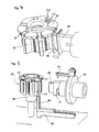
- zeigt die Vorrichtung aus
Figur 5 beim Verschieben des Spulenhalters vom Polstern auf den Wickeldorn, - Figur 7 -
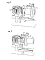
- zeigt die Vorrichtung aus
Figur 5 beim Bewickeln eines Spulenhalters, - Figur 8 -
- zeigt die Vorrichtung aus
Figur 5 unmittelbar vor Beginn des Verschiebens des Spulenhalters vom Wickeldorn auf den Polstern, - Figur 9 -
- zeigt die Vorrichtung aus
Figur 5 unmittelbar am Ende der Verschiebebewegung des Spulenhalters vom Wickeldorn auf den Polstern, - Figur 10 -
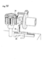
- zeigt die Vorrichtung aus
Figur 5 nachdem die Andockhülse wieder zurück in ihre Ausgangslage verschoben wurde. - Das erfindungsgemäße Verfahren beschreibt die Bewicklung eines Polsterns 18, der vorzugsweise aus Vollpolsegmenten 14 besteht, die durch geeignete Verbindungsbereiche 15 miteinander verbunden sind und so den Polstern 18 bilden. Vorzugsweise weisen die Vollpolsegmente 14 Formschlusselemente 17 zur Verbindung mit dem Joch auf.
- Für die Durchführung des erfindungsgemäßen Verfahrens werden weiterhin die Spulenhalter 19 benötigt, die auf die Polsegmente 14 aufgeschoben werden können. Vorzugsweise ist weiterhin ein Schaltungsträger 21 vorhanden, bei dem es sich beispielsweise um eine Platine handeln kann und der vorzugsweise zwei Funktionen erfüllt, nämlich zum einen das elektrische Kontaktieren und Verschalten der auf den Spulenträger 19 aufgenommenen Spulen, zum anderen das Fixieren der Spulenhalter 19 in ihrer am Polstern 18 aufgenommenen Position.
- Hierfür weisen die Spulenhalter 19 vorzugsweise Kontaktelemente 23 auf, die beispielsweise als Pins ausgebildet sein können und geeignet sind, in Kontaktgegenelemente 25 am Schaltungsträger, bei denen es sich beispielsweise um Schlitze handeln kann, in denen entsprechende Kontaktzungen angebracht sind, einzugreifen. Die Spulenwicklungen werden dabei an den Kontaktelementen 23 kontaktiert und über die in Schaltungsträger 21 integrierte elektrische Verschaltung, vorzugsweise in Stern- oder Dreiecksschaltung verschaltet. Vorzugsweise weist der Schaltungsträger 21 elektrische Verbindungselemente 24 auf, die beispielsweise als Steckerfahnen ausgebildet dazu dienen, den Stator mit seiner Stromversorgung zu verbinden.
- Alternativ kann der Schaltungsträger 18 selbst keine elektrischen Komponenten enthalten, sondern lediglich, beispielsweise als Kunststoffteil ausgeführt, als Träger für die schaltungsgerechte Verlegung der Drahtenden der einzelnen Wicklungen von den Spulenhaltern 19 zu den elektrischen Verbindungselementen 24 dienen.
- Bei dieser Variante kontaktiert im gezeigten Beispiel die Bewicklungseinrichtung den Draht zunächst auf dem Schaltungsträger 21, vorzugsweise auf einem auf diesem vorgesehenen elektrischen Verbindungselement 24, beispielsweise durch eine Schweißverbindung. Dann wird der Draht zu dem zu bewickelnden Spulenhalter 19 verlegt und dieser in seiner Bewicklungsposition auf dem Wickeldorn 26 bewickelt. Dabei entsteht eine Drahtverbindung von dem Schaltungsträger 21 zum Spulenhalter 19, welche aus einem Stück Draht besteht, welches den Abstand des auf dem Wickeldorn 26 positionierten Spulenhalters 19 zu dem Schaltungsträger 21 überbrückt. Bei Verschieben des Spulenhalters 19 auf den Polstern 18 würde sich so ein überschüssiges loses Stück Draht ergeben. Dieses lose Stück Draht wird daher vorteilhafterweise beim Verschieben des Spulenhalters 19 auf den Polstern 18 durch hierfür vorgesehene Drahtführungselemente so geführt, dass sich beim Einschieben des Spulenhalters 19 eine ausreichend gestraffte Verlegung dieses Drahtstücks ergibt. Die Drahtführungselemente können dabei beispielsweise in Form von Kunststoffnasen, beispielsweise im Bereich am Spulenhalter 21 vorgesehener Schlitze 25 vorgesehen sein, die den Draht derart führen, dass er in seiner endgültigen Verlegeposition, beispielsweise durch das Ausbilden von mäanderartigen Drahtschlaufen, eine ausreichende Straffung aufweist. Vorzugsweise kann in diesem Fall das andere Ende der Spulenwicklung nach dem Einschieben auf den Schaltungsträger 21 geführt und auf diesem verlegt und/oder kontaktiert werden, vorzugsweise an einem weiteren elektrischen Verbindungselement 24, so dass sich vorzugsweise eine Stern- oder Dreieckschaltung der Spulen ergibt. Dadurch ergibt sich bei diesem Ende der Spulenwicklung kein Drahtüberschuss.
- Zur Sicherung der Spulenhalter 19 auf den Polsegmenten 14 des Polsterns 18 können am Spulenhalter 19 Arretierelemente 20 vorgesehen sein, die geeignet sind, in entsprechende Aufnahmen einzugreifen und dadurch den Spulenhalter 19 in der aufgenommenen Position zu sichern. Beispielsweise kann das Arretierelement 20 als Arretierbrücke ausgebildet sein, die in Arretiergegenelemente 22 eingreift, die beispielsweise als gabelförmige Gegenelemente einer Clipsverbindung ausgebildet sind, wobei vorzugsweise die Verbindung aus Arretierelement und Arretiergegenelement so ausgebildet ist, dass deren Eingriffsrichtung parallel zu Aufschieberichtung des Spulenhalters 19 auf das Polsegment 14 verläuft.
- Der Wickeldorn 26 ist derart gestaltet, dass sein Querschnitt in etwa dem Querschnitt eines Polsegments 14 entspricht, so dass der Wickeldorn 26 fluchtend an ein Polsegment 14 angedockt bzw. in Verlängerung eines Polsegments positioniert werden kann, so dass aufgrund der ähnlichen Querschnitte ein Verschieben des Spulenhalters 19 auf den Wickeldorn 26 möglich ist. Zum Verschieben ist eine Verschiebeeinrichtung 30 vorgesehen, die geeignet ist, am Spulenhalter 19 anzugreifen. Vorzugsweise ist die Verschiebeeinrichtung 30 dabei so ausgebildet, dass sie in den für die Aufnahme der Spulenwicklung vorgesehenen Bereich des Spulenhalters 19 eingreifen kann. Beispielsweise durch eine gabelförmige Gestaltung. Die Verschiebeeinrichtung 30 kann dabei durch eine Verschiebeführung 29 vorzugsweise parallel zur Orientierung des Wickeldorns 26 bewegt werden und so den Spulenhalter 19 auf den Wickeldorn 26 schieben. Für die umgekehrte Verschiebebewegung ist es vorteilhaft, auf dem Wickeldorn 26 eine Andockhülse 31 vorzusehen. Bei der Andockhülse 31 handelt es sich um ein auf dem Wickeldorn 26 verschieblich ausfgenommenes Bauteil, welches geeignet ist, den Spulenhalter 19 vom Wickeldorn 26 auf ein Polsegment 14 zu verschieben. Vorzugsweise weist die Andockhülse 31 dabei einen Bereich 16 auf, der geometrisch so gestaltet ist, dass er den Angriff der Verschiebeeinrichtung 30 ermöglicht, wodurch es möglich ist, die Andockhülse 31 ebenfalls durch die Verschiebeeinrichtung 30 zu bewegen. Vorzugsweise weist die Vorrichtung eine insbesondere drehbare Polsternaufnahme 28 auf, die in der Lage ist, die Einheit 27 aus Polstern 18 und erfindungsgemäßem Spulenhaltersystem aufzunehmen und vorzugsweise um die Statorachse zu verschwenken, so dass die einzelnen Spulenhalter 19 nacheinander bewickelt werden können.
- Vorzugsweise ist zur Bewicklung ein Flyer-Wickelsystem vorgesehen, wobei der Flyerarm 33 an einer Flyerscheibe 32 aufgenommen ist, die vorzugsweise an einer Lagerung verschieblich entlang der Achse des Wickeldorns 26 aufgenommen ist, so dass die Bewicklungsmimik aus dem Arbeitsbereich der Verschiebeeinrichtung 30 gefahren werden kann. Gleichzeitig ist die Verschiebeeinrichtung vorzugsweise derart verschieb- oder verschwenkbar aufgenommen, dass sie um ein ungestörtes Bewickeln zu ermöglichen, außerhalb des Arbeitsbereichs des Flyerarms 33 positioniert werden kann.
Claims (13)
- Verfahren zur Bewicklung von Polsternen (18), insbesondere für Statoren von Innenläufermotoren,
wobei durch mindestens eine Verschiebeeinrichtung ein Spulenhalter (19) auf einen Wickeldorn (26) verschoben, der Spulenhalter (19) auf dem Wickeldorn (26) bewickelt und der bewickelte Spulenhalter (19) auf den Polstern (18) geschoben wird. - Verfahren nach Anspruch 1,
dadurch gekennzeichnet,
dass zum Bewickeln die Flyer-Wickeltechnik eingesetzt wird. - Verfahren nach Anspruch 1 oder 2,
dadurch gekennzeichnet,
dass zum Verschieben des Spulenhalters (19) auf den Wickeldorn (26) eine Verschiebeeinrichtung (30) mit dem zur Aufnahme der Wicklung bestimmten Bereich des Spulenhalters (19) in Eingriff gebracht wird. - Verfahren nach einem der Ansprüche 1 bis 3,
dadurch gekennzeichnet,
dass zum Verschieben des Spulenhalters (19) auf den Polstern (18) eine Verschiebeeinrichtung (30) mit einer Andockhülse (31) in Eingriff gebracht wird. - Verfahren nach einem der Ansprüche 1 bis 4,
dadurch gekennzeichnet,
dass die Verschiebung des Spulenhalters (19) in beide Verschieberichtungen durch die gleiche Verschiebeeinrichtung (30) erfolgt. - Verfahren nach einem der Ansprüche 1 bis 5,
dadurch gekennzeichnet,
dass der Spulenhalter (19) nach dem Aufschieben auf den Polstern (18) durch eine Clipsverbindung gesichert wird. - Verfahren nach einem der Ansprüche 1 bis 6,
dadurch gekennzeichnet,
dass die Kontaktierung des einen Endes des Wicklungsdrahts an einem auf dem Wicklungsträger (21) vorgesehenen elektrischen Verbindungselement (24) vorgenommen und der Draht von diesem bis zur Bewicklungsposition des Spulenhalters auf dem Wickeldornverlegt wird, wobei der so entstandene überschüssige Drahtabschnitt beim Verschieben des bewickelten Spulenhalters (19) auf den Polstern (18) durch Drahtführungselemente derart in seine endgültige Verlegeposition führen, dass sich eine ausreichend straffe Verlegung des Drahtabschnitts ergibt. - Vorrichtung zur Bewicklung von Polsternen, insbesondere für Statoren von Innenläufermotoren, insbesondere durch ein Verfahren nach Anspruch 1 bis 7,
die eine Polstern-Aufnahme (28) zur um eine erste Achse drehbaren Aufnahme des Polsterns (18) und einen Wickeldorn (26) aufweist, sowie eine Verschiebeeinrichtung (30), die geeignet ist, Spulenhalter (19) von dem Polstern (18) auf den Wickeldorn (26) und/oder von dem Wickeldorn (26) auf den Polstern (18) zu schieben. - Vorrichtung nach Anspruch 8,
dadurch gekennzeichnet,
dass zum Verschieben des Spulenhalters (19) auf den Polstern (18) die Verschiebeeinrichtung (30) mit einer Andockhülse (31) in Eingriff gebracht werden kann. - Vorrichtung nach Anspruch 8 oder 9,
dadurch gekennzeichnet,
dass zum Verschieben des Spulenhalters (19) auf den Polstern (18) und/oder den Wickeldorn (26) die Verschiebeeinrichtung (30) mit dem zu bewickelnden Bereich des Spulenhalters (18) in Eingriff gebracht werden kann. - Spulenhaltersystem zur Halterung von Spulenwicklungen auf Polsternen, insbesondere für Statoren von Innenläufermotoren, insbesondere bei deren Bewicklung durch ein Verfahren nach Anspruch 1 bis 7,
das eine Mehrzahl Spulenhalter und mindestens einen, vorzugsweise ringförmigen, Schaltungsträger (21) aufweist, die mechanisch, vorzugsweise durch eine Clipsverbindung, insbesondere mit zum Polstern (18) radialer Eingriffsrichtung, verbunden werden. - Spulenhaltersystem nach Anspruch 11,
dadurch gekennzeichnet,
dass der Schaltungsträger (21) die elektrische Verschaltung der Spulenwicklungen, vorzugsweise als Stern- und/oder Dreiecksverschaltung, aufweist. - Spulenhaltersysten nach Anspruch 11 oder 12,
dadurch gekennzeichnet,
dass der Schaltungsträger (21) und/oder die Spulenhalter (19) Drahtführungselemente, insbesondere Kunststoffnasen, aufweisen, die geeignet sind, bei der Verschiebung des Spulenhalters (19) vom Wickeldorn auf den Polstern (18) einen vom Schaltungsträger (21) zum Spulenhalter (19) verlaufenden Drahtabschnitt in seine endgültige Verlegeposition führen.
Priority Applications (3)
| Application Number | Priority Date | Filing Date | Title |
|---|---|---|---|
| PL11005137T PL2400638T3 (pl) | 2010-06-25 | 2011-06-22 | Sposób i urządzenie do nawijania gwiaździstych elementów biegunowych dla stojanów silników z wirnikiem wewnętrznym |
| SI201131769T SI2400638T1 (sl) | 2010-06-25 | 2011-06-22 | Postopek in naprava za navijanje zvezd polov za statorje motorjev z notranjim rotorjem |
| HRP20191376 HRP20191376T1 (hr) | 2010-06-25 | 2019-07-31 | Postupak i uređaj za namatanje namota za statore motora s unutarnjim rotorom |
Applications Claiming Priority (2)
| Application Number | Priority Date | Filing Date | Title |
|---|---|---|---|
| DE102010025134 | 2010-06-25 | ||
| DE102010026527A DE102010026527A1 (de) | 2010-06-25 | 2010-07-08 | Verfahren und Vorrichtung zur Bewicklung von Polsternen, insbesondere für Statoren von Innenläufermotoren |
Publications (3)
| Publication Number | Publication Date |
|---|---|
| EP2400638A2 true EP2400638A2 (de) | 2011-12-28 |
| EP2400638A3 EP2400638A3 (de) | 2015-11-11 |
| EP2400638B1 EP2400638B1 (de) | 2019-05-29 |
Family
ID=44856962
Family Applications (1)
| Application Number | Title | Priority Date | Filing Date |
|---|---|---|---|
| EP11005137.2A Not-in-force EP2400638B1 (de) | 2010-06-25 | 2011-06-22 | Verfahren und Vorrichtung zur Bewicklung von Polsternen für Statoren von Innenläufermotoren |
Country Status (7)
| Country | Link |
|---|---|
| EP (1) | EP2400638B1 (de) |
| DE (1) | DE102010026527A1 (de) |
| ES (1) | ES2742187T3 (de) |
| HR (1) | HRP20191376T1 (de) |
| HU (1) | HUE045011T2 (de) |
| PL (1) | PL2400638T3 (de) |
| SI (1) | SI2400638T1 (de) |
Cited By (2)
| Publication number | Priority date | Publication date | Assignee | Title |
|---|---|---|---|---|
| FR3010850A1 (fr) * | 2013-09-13 | 2015-03-20 | Valeo Equip Electr Moteur | Bridage d'un interconnecteur sur un stator |
| CN119298564A (zh) * | 2024-10-18 | 2025-01-10 | 湖南龙德晟机电科技有限公司 | 一种电机绕线用内绕紧线装置 |
Families Citing this family (3)
| Publication number | Priority date | Publication date | Assignee | Title |
|---|---|---|---|---|
| DE102014002221A1 (de) | 2014-02-21 | 2015-08-27 | Elmotec Statomat Vertriebs Gmbh | Verfahren und Vorrichtung zum Wickeln von Polsternen |
| EP4264796A1 (de) | 2020-12-21 | 2023-10-25 | Pierburg Pump Technology GmbH | Motorstator für einen elektromotor und verfahren zur herstellung des motorstators |
| DE102023104359B4 (de) | 2023-02-22 | 2025-03-27 | Aumann Espelkamp Gmbh | Wickelvorrichtung und Verfahren zum Herstellen einer Anordnung für eine elektrische Maschine |
Citations (2)
| Publication number | Priority date | Publication date | Assignee | Title |
|---|---|---|---|---|
| EP0849857A1 (de) | 1996-12-18 | 1998-06-24 | Siemens Aktiengesellschaft | Stator für elektrodynamische Maschinen und Verfahren zu deren Herstellung |
| DE102006041715A1 (de) | 2006-09-06 | 2008-03-27 | Wilo Ag | Spulenträgervorrichtung |
Family Cites Families (10)
| Publication number | Priority date | Publication date | Assignee | Title |
|---|---|---|---|---|
| DE1589530A1 (de) * | 1967-06-21 | 1970-05-14 | Blume & Redecker Gmbh | Spulenwickelmaschine |
| TW517430B (en) * | 2000-06-02 | 2003-01-11 | Moric Kabushiki Kaisha | Coil winding for DC machine |
| DE10112268A1 (de) * | 2001-03-14 | 2002-10-02 | Siemens Ag | Elektrische Maschine |
| JP2002354733A (ja) * | 2001-03-19 | 2002-12-06 | Denso Corp | 直流モータ |
| JP3930419B2 (ja) * | 2001-12-13 | 2007-06-13 | アスモ株式会社 | 回転電機製造方法 |
| JP2005102402A (ja) * | 2003-09-24 | 2005-04-14 | Aisin Aw Co Ltd | ステータ製造装置 |
| DE102004007475A1 (de) * | 2004-02-13 | 2005-09-15 | Elmotec Statomat Vertriebs Gmbh | Vorrichtung und Verfahren zum Herstellen von Statoren für elektrische Motoren und Generatoren |
| WO2006137125A1 (ja) * | 2005-06-21 | 2006-12-28 | Mitsubishi Denki Kabushiki Kaisha | 回転電動機の電機子、回転電動機及びその製造方法 |
| DE102006025778A1 (de) * | 2006-05-31 | 2007-12-06 | Wilo Ag | Verfahren zur Herstellung eines Stators und zugehöriger Stator |
| JP2008172863A (ja) * | 2007-01-09 | 2008-07-24 | Asmo Co Ltd | 回転電機及びその製造方法 |
-
2010
- 2010-07-08 DE DE102010026527A patent/DE102010026527A1/de not_active Withdrawn
-
2011
- 2011-06-22 ES ES11005137T patent/ES2742187T3/es active Active
- 2011-06-22 HU HUE11005137 patent/HUE045011T2/hu unknown
- 2011-06-22 PL PL11005137T patent/PL2400638T3/pl unknown
- 2011-06-22 SI SI201131769T patent/SI2400638T1/sl unknown
- 2011-06-22 EP EP11005137.2A patent/EP2400638B1/de not_active Not-in-force
-
2019
- 2019-07-31 HR HRP20191376 patent/HRP20191376T1/hr unknown
Patent Citations (2)
| Publication number | Priority date | Publication date | Assignee | Title |
|---|---|---|---|---|
| EP0849857A1 (de) | 1996-12-18 | 1998-06-24 | Siemens Aktiengesellschaft | Stator für elektrodynamische Maschinen und Verfahren zu deren Herstellung |
| DE102006041715A1 (de) | 2006-09-06 | 2008-03-27 | Wilo Ag | Spulenträgervorrichtung |
Cited By (2)
| Publication number | Priority date | Publication date | Assignee | Title |
|---|---|---|---|---|
| FR3010850A1 (fr) * | 2013-09-13 | 2015-03-20 | Valeo Equip Electr Moteur | Bridage d'un interconnecteur sur un stator |
| CN119298564A (zh) * | 2024-10-18 | 2025-01-10 | 湖南龙德晟机电科技有限公司 | 一种电机绕线用内绕紧线装置 |
Also Published As
| Publication number | Publication date |
|---|---|
| EP2400638B1 (de) | 2019-05-29 |
| EP2400638A3 (de) | 2015-11-11 |
| PL2400638T3 (pl) | 2019-11-29 |
| HUE045011T2 (hu) | 2019-11-28 |
| ES2742187T3 (es) | 2020-02-13 |
| DE102010026527A1 (de) | 2012-03-29 |
| SI2400638T1 (sl) | 2019-10-30 |
| HRP20191376T1 (hr) | 2019-11-01 |
Similar Documents
| Publication | Publication Date | Title |
|---|---|---|
| EP2477315B1 (de) | Nadelwickelsystem für zu bewickelnde Wicklungsträger, Verfahren zum Bewickeln von Wicklungsträgern mit verteilter Wicklung, Innenläufer-Stator, Aussenläufer-Rotor und Wicklungsträger für Elektromotoren mit verteilter Wicklung | |
| EP0968563B1 (de) | Verfahren und vorrichtung zum herstellen von wellenwicklungen für elektrische maschinen | |
| DE102008059884A1 (de) | Motor für eine elektrische Servolenkungsvorrichtung | |
| EP2059991B1 (de) | Spulenträgervorrichtung | |
| EP2400638B1 (de) | Verfahren und Vorrichtung zur Bewicklung von Polsternen für Statoren von Innenläufermotoren | |
| DE102014208909A1 (de) | Rotierende elektrische Vorrichtung | |
| DE3610233C2 (de) | ||
| EP1016199B1 (de) | Stator für einen elektromotor, insbesondere bürstenlosen gleichstrommotor | |
| EP3245717B1 (de) | Verfahren zum bewickeln eines wicklungsträgers | |
| DE102011011809A1 (de) | Polkette | |
| DE102020117771A1 (de) | Verfahren und Vorrichtung zum Fügen eines Wicklungspakets in ein Gehäuse eines Bauteils einer elektrischen Maschine, insbesondere eines Stators oder eines Rotors, sowie Stützvorrichtung | |
| DE112020002755T5 (de) | Verfahren zur Bildung eines Stators, der Schrägschlitze aufweist, und Stator, der Schrägschlitze umfasst | |
| EP2605377B1 (de) | Verfahren und Vorrichtung zur Herstellung eines Stators sowie Stator | |
| EP2845300B1 (de) | Vorrichtung und verfahren zur bewicklung eines elektromotor-blechpakets mit einer magnetspule | |
| DE102020205053A1 (de) | Stator für eine elektrische Maschine und Formvorrichtung für einen Stator | |
| EP2269285A2 (de) | Verfahren und vorrichtung zur herstellung einer elektrischen wicklung | |
| DE102013000370B4 (de) | Wicklungsträger, insbesondere Stator oder Rotor einer Drehstrom-Elektromaschine und Verfahren zur Herstellung der Wicklung eines Wicklungsträgers | |
| EP2690634B1 (de) | Spule | |
| DE102016002207A1 (de) | Verfahren zur Herstellung eines Stators durch Nadelwickeln | |
| EP3223410B1 (de) | Verfahren zum bewickeln eines wicklungsträgers | |
| EP2479869B1 (de) | Fertigung eines Elektromotorenstators | |
| DE102007038429A1 (de) | Verfahren und Vorrichtung zur Herstellung einer elektrischen Wicklung | |
| DE102009055043A1 (de) | Verfahren zur Herstellung einer verteilten Schleifenwicklung für mehrphasige Systeme | |
| DE102004037639A1 (de) | Mehrphasenentwicklung, Elektromotor und Fertigungsverfahren | |
| DE102004010758A1 (de) | Verfahren zum Aufbringen einer elektrischen Wicklung auf einen magnetisch leitfähigen Körper eines Hauptelements einer elektrischen Maschine |
Legal Events
| Date | Code | Title | Description |
|---|---|---|---|
| AK | Designated contracting states |
Kind code of ref document: A2 Designated state(s): AL AT BE BG CH CY CZ DE DK EE ES FI FR GB GR HR HU IE IS IT LI LT LU LV MC MK MT NL NO PL PT RO RS SE SI SK SM TR |
|
| AX | Request for extension of the european patent |
Extension state: BA ME |
|
| PUAI | Public reference made under article 153(3) epc to a published international application that has entered the european phase |
Free format text: ORIGINAL CODE: 0009012 |
|
| RIC1 | Information provided on ipc code assigned before grant |
Ipc: H02K 15/06 20060101ALI20150602BHEP Ipc: H02K 3/52 20060101AFI20150602BHEP Ipc: H02K 15/04 20060101ALI20150602BHEP Ipc: H02K 3/28 20060101ALI20150602BHEP |
|
| PUAL | Search report despatched |
Free format text: ORIGINAL CODE: 0009013 |
|
| AK | Designated contracting states |
Kind code of ref document: A3 Designated state(s): AL AT BE BG CH CY CZ DE DK EE ES FI FR GB GR HR HU IE IS IT LI LT LU LV MC MK MT NL NO PL PT RO RS SE SI SK SM TR |
|
| AX | Request for extension of the european patent |
Extension state: BA ME |
|
| RIC1 | Information provided on ipc code assigned before grant |
Ipc: H02K 15/04 20060101ALI20151002BHEP Ipc: H02K 15/06 20060101ALI20151002BHEP Ipc: H02K 3/52 20060101AFI20151002BHEP Ipc: H02K 3/28 20060101ALI20151002BHEP |
|
| 17P | Request for examination filed |
Effective date: 20160509 |
|
| RBV | Designated contracting states (corrected) |
Designated state(s): AL AT BE BG CH CY CZ DE DK EE ES FI FR GB GR HR HU IE IS IT LI LT LU LV MC MK MT NL NO PL PT RO RS SE SI SK SM TR |
|
| STAA | Information on the status of an ep patent application or granted ep patent |
Free format text: STATUS: EXAMINATION IS IN PROGRESS |
|
| RAP1 | Party data changed (applicant data changed or rights of an application transferred) |
Owner name: AUMANN ESPELKAMP GMBH |
|
| 17Q | First examination report despatched |
Effective date: 20180214 |
|
| GRAP | Despatch of communication of intention to grant a patent |
Free format text: ORIGINAL CODE: EPIDOSNIGR1 |
|
| STAA | Information on the status of an ep patent application or granted ep patent |
Free format text: STATUS: GRANT OF PATENT IS INTENDED |
|
| INTG | Intention to grant announced |
Effective date: 20190212 |
|
| GRAS | Grant fee paid |
Free format text: ORIGINAL CODE: EPIDOSNIGR3 |
|
| GRAA | (expected) grant |
Free format text: ORIGINAL CODE: 0009210 |
|
| STAA | Information on the status of an ep patent application or granted ep patent |
Free format text: STATUS: THE PATENT HAS BEEN GRANTED |
|
| AK | Designated contracting states |
Kind code of ref document: B1 Designated state(s): AL AT BE BG CH CY CZ DE DK EE ES FI FR GB GR HR HU IE IS IT LI LT LU LV MC MK MT NL NO PL PT RO RS SE SI SK SM TR |
|
| REG | Reference to a national code |
Ref country code: GB Ref legal event code: FG4D Free format text: NOT ENGLISH |
|
| REG | Reference to a national code |
Ref country code: CH Ref legal event code: EP |
|
| REG | Reference to a national code |
Ref country code: AT Ref legal event code: REF Ref document number: 1138844 Country of ref document: AT Kind code of ref document: T Effective date: 20190615 |
|
| REG | Reference to a national code |
Ref country code: DE Ref legal event code: R096 Ref document number: 502011015745 Country of ref document: DE |
|
| REG | Reference to a national code |
Ref country code: IE Ref legal event code: FG4D Free format text: LANGUAGE OF EP DOCUMENT: GERMAN |
|
| REG | Reference to a national code |
Ref country code: CH Ref legal event code: NV Representative=s name: SCHMAUDER AND PARTNER AG PATENT- UND MARKENANW, CH |
|
| REG | Reference to a national code |
Ref country code: NL Ref legal event code: FP |
|
| REG | Reference to a national code |
Ref country code: RO Ref legal event code: EPE |
|
| REG | Reference to a national code |
Ref country code: HR Ref legal event code: TUEP Ref document number: P20191376 Country of ref document: HR |
|
| REG | Reference to a national code |
Ref country code: SE Ref legal event code: TRGR |
|
| REG | Reference to a national code |
Ref country code: LT Ref legal event code: MG4D |
|
| REG | Reference to a national code |
Ref country code: HR Ref legal event code: ODRP Ref document number: P20191376 Country of ref document: HR Payment date: 20190731 Year of fee payment: 9 |
|
| PG25 | Lapsed in a contracting state [announced via postgrant information from national office to epo] |
Ref country code: LT Free format text: LAPSE BECAUSE OF FAILURE TO SUBMIT A TRANSLATION OF THE DESCRIPTION OR TO PAY THE FEE WITHIN THE PRESCRIBED TIME-LIMIT Effective date: 20190529 Ref country code: NO Free format text: LAPSE BECAUSE OF FAILURE TO SUBMIT A TRANSLATION OF THE DESCRIPTION OR TO PAY THE FEE WITHIN THE PRESCRIBED TIME-LIMIT Effective date: 20190829 Ref country code: FI Free format text: LAPSE BECAUSE OF FAILURE TO SUBMIT A TRANSLATION OF THE DESCRIPTION OR TO PAY THE FEE WITHIN THE PRESCRIBED TIME-LIMIT Effective date: 20190529 Ref country code: AL Free format text: LAPSE BECAUSE OF FAILURE TO SUBMIT A TRANSLATION OF THE DESCRIPTION OR TO PAY THE FEE WITHIN THE PRESCRIBED TIME-LIMIT Effective date: 20190529 Ref country code: PT Free format text: LAPSE BECAUSE OF FAILURE TO SUBMIT A TRANSLATION OF THE DESCRIPTION OR TO PAY THE FEE WITHIN THE PRESCRIBED TIME-LIMIT Effective date: 20190930 |
|
| PGFP | Annual fee paid to national office [announced via postgrant information from national office to epo] |
Ref country code: FR Payment date: 20190729 Year of fee payment: 10 |
|
| REG | Reference to a national code |
Ref country code: HR Ref legal event code: T1PR Ref document number: P20191376 Country of ref document: HR |
|
| REG | Reference to a national code |
Ref country code: SK Ref legal event code: T3 Ref document number: E 31904 Country of ref document: SK |
|
| REG | Reference to a national code |
Ref country code: HU Ref legal event code: AG4A Ref document number: E045011 Country of ref document: HU |
|
| PG25 | Lapsed in a contracting state [announced via postgrant information from national office to epo] |
Ref country code: GR Free format text: LAPSE BECAUSE OF FAILURE TO SUBMIT A TRANSLATION OF THE DESCRIPTION OR TO PAY THE FEE WITHIN THE PRESCRIBED TIME-LIMIT Effective date: 20190830 Ref country code: RS Free format text: LAPSE BECAUSE OF FAILURE TO SUBMIT A TRANSLATION OF THE DESCRIPTION OR TO PAY THE FEE WITHIN THE PRESCRIBED TIME-LIMIT Effective date: 20190529 Ref country code: LV Free format text: LAPSE BECAUSE OF FAILURE TO SUBMIT A TRANSLATION OF THE DESCRIPTION OR TO PAY THE FEE WITHIN THE PRESCRIBED TIME-LIMIT Effective date: 20190529 |
|
| PG25 | Lapsed in a contracting state [announced via postgrant information from national office to epo] |
Ref country code: EE Free format text: LAPSE BECAUSE OF FAILURE TO SUBMIT A TRANSLATION OF THE DESCRIPTION OR TO PAY THE FEE WITHIN THE PRESCRIBED TIME-LIMIT Effective date: 20190529 Ref country code: DK Free format text: LAPSE BECAUSE OF FAILURE TO SUBMIT A TRANSLATION OF THE DESCRIPTION OR TO PAY THE FEE WITHIN THE PRESCRIBED TIME-LIMIT Effective date: 20190529 |
|
| REG | Reference to a national code |
Ref country code: ES Ref legal event code: FG2A Ref document number: 2742187 Country of ref document: ES Kind code of ref document: T3 Effective date: 20200213 |
|
| PG25 | Lapsed in a contracting state [announced via postgrant information from national office to epo] |
Ref country code: SM Free format text: LAPSE BECAUSE OF FAILURE TO SUBMIT A TRANSLATION OF THE DESCRIPTION OR TO PAY THE FEE WITHIN THE PRESCRIBED TIME-LIMIT Effective date: 20190529 Ref country code: MC Free format text: LAPSE BECAUSE OF FAILURE TO SUBMIT A TRANSLATION OF THE DESCRIPTION OR TO PAY THE FEE WITHIN THE PRESCRIBED TIME-LIMIT Effective date: 20190529 |
|
| REG | Reference to a national code |
Ref country code: DE Ref legal event code: R097 Ref document number: 502011015745 Country of ref document: DE |
|
| REG | Reference to a national code |
Ref country code: BE Ref legal event code: MM Effective date: 20190630 |
|
| PG25 | Lapsed in a contracting state [announced via postgrant information from national office to epo] |
Ref country code: TR Free format text: LAPSE BECAUSE OF FAILURE TO SUBMIT A TRANSLATION OF THE DESCRIPTION OR TO PAY THE FEE WITHIN THE PRESCRIBED TIME-LIMIT Effective date: 20190529 |
|
| PLBE | No opposition filed within time limit |
Free format text: ORIGINAL CODE: 0009261 |
|
| STAA | Information on the status of an ep patent application or granted ep patent |
Free format text: STATUS: NO OPPOSITION FILED WITHIN TIME LIMIT |
|
| REG | Reference to a national code |
Ref country code: DE Ref legal event code: R082 Ref document number: 502011015745 Country of ref document: DE Representative=s name: BOEHMERT & BOEHMERT ANWALTSPARTNERSCHAFT MBB -, DE Ref country code: DE Ref legal event code: R082 Ref document number: 502011015745 Country of ref document: DE |
|
| PG25 | Lapsed in a contracting state [announced via postgrant information from national office to epo] |
Ref country code: IE Free format text: LAPSE BECAUSE OF NON-PAYMENT OF DUE FEES Effective date: 20190622 |
|
| 26N | No opposition filed |
Effective date: 20200303 |
|
| PG25 | Lapsed in a contracting state [announced via postgrant information from national office to epo] |
Ref country code: BE Free format text: LAPSE BECAUSE OF NON-PAYMENT OF DUE FEES Effective date: 20190630 Ref country code: LU Free format text: LAPSE BECAUSE OF NON-PAYMENT OF DUE FEES Effective date: 20190622 |
|
| REG | Reference to a national code |
Ref country code: DE Ref legal event code: R082 Ref document number: 502011015745 Country of ref document: DE Representative=s name: BOEHMERT & BOEHMERT ANWALTSPARTNERSCHAFT MBB -, DE |
|
| REG | Reference to a national code |
Ref country code: HR Ref legal event code: ODRP Ref document number: P20191376 Country of ref document: HR Payment date: 20200618 Year of fee payment: 10 |
|
| PGFP | Annual fee paid to national office [announced via postgrant information from national office to epo] |
Ref country code: RO Payment date: 20200622 Year of fee payment: 10 Ref country code: DE Payment date: 20200618 Year of fee payment: 10 Ref country code: CH Payment date: 20200618 Year of fee payment: 10 Ref country code: CZ Payment date: 20200619 Year of fee payment: 10 |
|
| PGFP | Annual fee paid to national office [announced via postgrant information from national office to epo] |
Ref country code: HR Payment date: 20200618 Year of fee payment: 10 Ref country code: PL Payment date: 20200619 Year of fee payment: 10 Ref country code: GB Payment date: 20200625 Year of fee payment: 10 Ref country code: BG Payment date: 20200619 Year of fee payment: 10 Ref country code: SE Payment date: 20200625 Year of fee payment: 10 Ref country code: SI Payment date: 20200617 Year of fee payment: 10 Ref country code: NL Payment date: 20200625 Year of fee payment: 10 Ref country code: SK Payment date: 20200619 Year of fee payment: 10 |
|
| PGFP | Annual fee paid to national office [announced via postgrant information from national office to epo] |
Ref country code: AT Payment date: 20200619 Year of fee payment: 10 |
|
| PGFP | Annual fee paid to national office [announced via postgrant information from national office to epo] |
Ref country code: ES Payment date: 20200824 Year of fee payment: 10 |
|
| PGFP | Annual fee paid to national office [announced via postgrant information from national office to epo] |
Ref country code: IT Payment date: 20200625 Year of fee payment: 10 Ref country code: HU Payment date: 20200722 Year of fee payment: 10 |
|
| PG25 | Lapsed in a contracting state [announced via postgrant information from national office to epo] |
Ref country code: CY Free format text: LAPSE BECAUSE OF FAILURE TO SUBMIT A TRANSLATION OF THE DESCRIPTION OR TO PAY THE FEE WITHIN THE PRESCRIBED TIME-LIMIT Effective date: 20190529 |
|
| PG25 | Lapsed in a contracting state [announced via postgrant information from national office to epo] |
Ref country code: IS Free format text: LAPSE BECAUSE OF FAILURE TO SUBMIT A TRANSLATION OF THE DESCRIPTION OR TO PAY THE FEE WITHIN THE PRESCRIBED TIME-LIMIT Effective date: 20190929 |
|
| PG25 | Lapsed in a contracting state [announced via postgrant information from national office to epo] |
Ref country code: MT Free format text: LAPSE BECAUSE OF FAILURE TO SUBMIT A TRANSLATION OF THE DESCRIPTION OR TO PAY THE FEE WITHIN THE PRESCRIBED TIME-LIMIT Effective date: 20190529 |
|
| REG | Reference to a national code |
Ref country code: DE Ref legal event code: R119 Ref document number: 502011015745 Country of ref document: DE |
|
| REG | Reference to a national code |
Ref country code: HR Ref legal event code: PBON Ref document number: P20191376 Country of ref document: HR Effective date: 20210622 |
|
| REG | Reference to a national code |
Ref country code: SE Ref legal event code: EUG |
|
| PG25 | Lapsed in a contracting state [announced via postgrant information from national office to epo] |
Ref country code: RO Free format text: LAPSE BECAUSE OF NON-PAYMENT OF DUE FEES Effective date: 20210622 Ref country code: CZ Free format text: LAPSE BECAUSE OF NON-PAYMENT OF DUE FEES Effective date: 20210622 |
|
| REG | Reference to a national code |
Ref country code: CH Ref legal event code: PL |
|
| REG | Reference to a national code |
Ref country code: NL Ref legal event code: MM Effective date: 20210701 |
|
| REG | Reference to a national code |
Ref country code: AT Ref legal event code: MM01 Ref document number: 1138844 Country of ref document: AT Kind code of ref document: T Effective date: 20210622 |
|
| GBPC | Gb: european patent ceased through non-payment of renewal fee |
Effective date: 20210622 |
|
| REG | Reference to a national code |
Ref country code: SK Ref legal event code: MM4A Ref document number: E 31904 Country of ref document: SK Effective date: 20210622 |
|
| PG25 | Lapsed in a contracting state [announced via postgrant information from national office to epo] |
Ref country code: LI Free format text: LAPSE BECAUSE OF NON-PAYMENT OF DUE FEES Effective date: 20210630 Ref country code: HU Free format text: LAPSE BECAUSE OF NON-PAYMENT OF DUE FEES Effective date: 20210623 Ref country code: GB Free format text: LAPSE BECAUSE OF NON-PAYMENT OF DUE FEES Effective date: 20210622 Ref country code: DE Free format text: LAPSE BECAUSE OF NON-PAYMENT OF DUE FEES Effective date: 20220101 Ref country code: CH Free format text: LAPSE BECAUSE OF NON-PAYMENT OF DUE FEES Effective date: 20210630 Ref country code: BG Free format text: LAPSE BECAUSE OF NON-PAYMENT OF DUE FEES Effective date: 20211231 Ref country code: AT Free format text: LAPSE BECAUSE OF NON-PAYMENT OF DUE FEES Effective date: 20210622 |
|
| REG | Reference to a national code |
Ref country code: SI Ref legal event code: KO00 Effective date: 20220309 |
|
| PG25 | Lapsed in a contracting state [announced via postgrant information from national office to epo] |
Ref country code: SK Free format text: LAPSE BECAUSE OF NON-PAYMENT OF DUE FEES Effective date: 20210622 Ref country code: SE Free format text: LAPSE BECAUSE OF NON-PAYMENT OF DUE FEES Effective date: 20210623 Ref country code: NL Free format text: LAPSE BECAUSE OF NON-PAYMENT OF DUE FEES Effective date: 20210701 Ref country code: HR Free format text: LAPSE BECAUSE OF NON-PAYMENT OF DUE FEES Effective date: 20210622 Ref country code: FR Free format text: LAPSE BECAUSE OF NON-PAYMENT OF DUE FEES Effective date: 20210630 |
|
| PG25 | Lapsed in a contracting state [announced via postgrant information from national office to epo] |
Ref country code: MK Free format text: LAPSE BECAUSE OF FAILURE TO SUBMIT A TRANSLATION OF THE DESCRIPTION OR TO PAY THE FEE WITHIN THE PRESCRIBED TIME-LIMIT Effective date: 20190529 |
|
| PG25 | Lapsed in a contracting state [announced via postgrant information from national office to epo] |
Ref country code: IT Free format text: LAPSE BECAUSE OF NON-PAYMENT OF DUE FEES Effective date: 20210622 |
|
| REG | Reference to a national code |
Ref country code: ES Ref legal event code: FD2A Effective date: 20220902 |
|
| PG25 | Lapsed in a contracting state [announced via postgrant information from national office to epo] |
Ref country code: ES Free format text: LAPSE BECAUSE OF NON-PAYMENT OF DUE FEES Effective date: 20210623 |
|
| PG25 | Lapsed in a contracting state [announced via postgrant information from national office to epo] |
Ref country code: PL Free format text: LAPSE BECAUSE OF NON-PAYMENT OF DUE FEES Effective date: 20210622 |