EP2059991B1 - Spulenträgervorrichtung - Google Patents
Spulenträgervorrichtung Download PDFInfo
- Publication number
- EP2059991B1 EP2059991B1 EP07786111A EP07786111A EP2059991B1 EP 2059991 B1 EP2059991 B1 EP 2059991B1 EP 07786111 A EP07786111 A EP 07786111A EP 07786111 A EP07786111 A EP 07786111A EP 2059991 B1 EP2059991 B1 EP 2059991B1
- Authority
- EP
- European Patent Office
- Prior art keywords
- coil
- coil former
- formers
- mounting element
- winding
- Prior art date
- Legal status (The legal status is an assumption and is not a legal conclusion. Google has not performed a legal analysis and makes no representation as to the accuracy of the status listed.)
- Active
Links
- 238000004804 winding Methods 0.000 claims abstract description 39
- 238000000034 method Methods 0.000 claims description 13
- 239000000969 carrier Substances 0.000 description 11
- 238000004519 manufacturing process Methods 0.000 description 6
- 238000009413 insulation Methods 0.000 description 3
- 239000004020 conductor Substances 0.000 description 2
- 238000006073 displacement reaction Methods 0.000 description 2
- 238000005516 engineering process Methods 0.000 description 2
- 238000005476 soldering Methods 0.000 description 2
- 241001136792 Alle Species 0.000 description 1
- 241000255927 Papilio polyxenes Species 0.000 description 1
- 238000009434 installation Methods 0.000 description 1
- 238000011031 large-scale manufacturing process Methods 0.000 description 1
- 230000007704 transition Effects 0.000 description 1
- 238000003466 welding Methods 0.000 description 1
Images

Classifications
-
- H—ELECTRICITY
- H02—GENERATION; CONVERSION OR DISTRIBUTION OF ELECTRIC POWER
- H02K—DYNAMO-ELECTRIC MACHINES
- H02K3/00—Details of windings
- H02K3/32—Windings characterised by the shape, form or construction of the insulation
- H02K3/325—Windings characterised by the shape, form or construction of the insulation for windings on salient poles, such as claw-shaped poles
-
- H—ELECTRICITY
- H02—GENERATION; CONVERSION OR DISTRIBUTION OF ELECTRIC POWER
- H02K—DYNAMO-ELECTRIC MACHINES
- H02K1/00—Details of the magnetic circuit
- H02K1/06—Details of the magnetic circuit characterised by the shape, form or construction
- H02K1/12—Stationary parts of the magnetic circuit
- H02K1/14—Stator cores with salient poles
- H02K1/146—Stator cores with salient poles consisting of a generally annular yoke with salient poles
- H02K1/148—Sectional cores
-
- H—ELECTRICITY
- H02—GENERATION; CONVERSION OR DISTRIBUTION OF ELECTRIC POWER
- H02K—DYNAMO-ELECTRIC MACHINES
- H02K3/00—Details of windings
- H02K3/46—Fastening of windings on the stator or rotor structure
- H02K3/52—Fastening salient pole windings or connections thereto
- H02K3/521—Fastening salient pole windings or connections thereto applicable to stators only
- H02K3/522—Fastening salient pole windings or connections thereto applicable to stators only for generally annular cores with salient poles
-
- H—ELECTRICITY
- H02—GENERATION; CONVERSION OR DISTRIBUTION OF ELECTRIC POWER
- H02K—DYNAMO-ELECTRIC MACHINES
- H02K15/00—Methods or apparatus specially adapted for manufacturing, assembling, maintaining or repairing of dynamo-electric machines
- H02K15/04—Methods or apparatus specially adapted for manufacturing, assembling, maintaining or repairing of dynamo-electric machines of windings, prior to mounting into machines
-
- Y—GENERAL TAGGING OF NEW TECHNOLOGICAL DEVELOPMENTS; GENERAL TAGGING OF CROSS-SECTIONAL TECHNOLOGIES SPANNING OVER SEVERAL SECTIONS OF THE IPC; TECHNICAL SUBJECTS COVERED BY FORMER USPC CROSS-REFERENCE ART COLLECTIONS [XRACs] AND DIGESTS
- Y10—TECHNICAL SUBJECTS COVERED BY FORMER USPC
- Y10T—TECHNICAL SUBJECTS COVERED BY FORMER US CLASSIFICATION
- Y10T29/00—Metal working
- Y10T29/49—Method of mechanical manufacture
- Y10T29/49002—Electrical device making
- Y10T29/4902—Electromagnet, transformer or inductor
- Y10T29/49021—Magnetic recording reproducing transducer [e.g., tape head, core, etc.]
- Y10T29/49032—Fabricating head structure or component thereof
- Y10T29/4906—Providing winding
- Y10T29/49062—Multilayered winding
-
- Y—GENERAL TAGGING OF NEW TECHNOLOGICAL DEVELOPMENTS; GENERAL TAGGING OF CROSS-SECTIONAL TECHNOLOGIES SPANNING OVER SEVERAL SECTIONS OF THE IPC; TECHNICAL SUBJECTS COVERED BY FORMER USPC CROSS-REFERENCE ART COLLECTIONS [XRACs] AND DIGESTS
- Y10—TECHNICAL SUBJECTS COVERED BY FORMER USPC
- Y10T—TECHNICAL SUBJECTS COVERED BY FORMER US CLASSIFICATION
- Y10T29/00—Metal working
- Y10T29/49—Method of mechanical manufacture
- Y10T29/49002—Electrical device making
- Y10T29/4902—Electromagnet, transformer or inductor
- Y10T29/49021—Magnetic recording reproducing transducer [e.g., tape head, core, etc.]
- Y10T29/49032—Fabricating head structure or component thereof
- Y10T29/4906—Providing winding
- Y10T29/49066—Preformed winding
-
- Y—GENERAL TAGGING OF NEW TECHNOLOGICAL DEVELOPMENTS; GENERAL TAGGING OF CROSS-SECTIONAL TECHNOLOGIES SPANNING OVER SEVERAL SECTIONS OF THE IPC; TECHNICAL SUBJECTS COVERED BY FORMER USPC CROSS-REFERENCE ART COLLECTIONS [XRACs] AND DIGESTS
- Y10—TECHNICAL SUBJECTS COVERED BY FORMER USPC
- Y10T—TECHNICAL SUBJECTS COVERED BY FORMER US CLASSIFICATION
- Y10T29/00—Metal working
- Y10T29/49—Method of mechanical manufacture
- Y10T29/49002—Electrical device making
- Y10T29/4902—Electromagnet, transformer or inductor
- Y10T29/49071—Electromagnet, transformer or inductor by winding or coiling
-
- Y—GENERAL TAGGING OF NEW TECHNOLOGICAL DEVELOPMENTS; GENERAL TAGGING OF CROSS-SECTIONAL TECHNOLOGIES SPANNING OVER SEVERAL SECTIONS OF THE IPC; TECHNICAL SUBJECTS COVERED BY FORMER USPC CROSS-REFERENCE ART COLLECTIONS [XRACs] AND DIGESTS
- Y10—TECHNICAL SUBJECTS COVERED BY FORMER USPC
- Y10T—TECHNICAL SUBJECTS COVERED BY FORMER US CLASSIFICATION
- Y10T29/00—Metal working
- Y10T29/49—Method of mechanical manufacture
- Y10T29/49002—Electrical device making
- Y10T29/4902—Electromagnet, transformer or inductor
- Y10T29/49073—Electromagnet, transformer or inductor by assembling coil and core
Definitions
- the invention relates to a Spulenaboorraum for an electrical machine, in particular for an electric motor with coil carriers made of plastic, on which coils of the stator can be wound.
- a coil carrier device is from the US 6081059 , known.
- the object of the invention is to simplify manufacturing and assembly of electrical machines and to facilitate mass production.
- the bobbin for winding particularly well for Bewicklungs- and assembly machines are accessible and the bobbins are connected to each other from the outset.
- the bobbins can be wound individually or in pairs, the bobbins always assume safe defined positions.
- the central support element in addition to its holding function in addition tasks in particular take on electrical / electronic fields. The number of parts is significantly reduced and the Increased manufacturing security and manufacturing accuracy. There is only one support element required and it is created a single, easy-to-test unit.
- a flat support element 1 of a bobbin device 2 made of plastic coil support 3 are integrally formed of plastic, on which the individual coils 13 of a stator are wound large-scale production.
- the coil carrier 3 with its hollow plastic core 8, on which the wire of the coil is wound, is elongate, ie it has a greater length L than width B, with its longitudinal axis 9 being arranged radially to the carrier element 1.
- the individual coil carriers 3 are distributed symmetrically around the star in a star shape Central Kunststoffismeetement 1 and are connected by hinges in particular film hinges 4 with this.
- the support element 1 to which preferably conductor tracks are applied via MID technology (Model Interconnect Devices), the electrical interconnection of the individual coils is produced to each other.
- this MID structure serves as a carrier and interconnection instrument for all or parts of the necessary electrical / electronic components.
- electrical connections 5 are attached at suitable locations on the support element.
- the support member is used as a circuit board.
- the coil carrier device 2 has on the carrier element 1 in the plane star-shaped distributed four or more coil carrier 3 as insulation body on which the individual coils are wound. Since each bobbin 3 with its plastic core 8, on which lie the windings, an elongated shape and its longitudinal axis 9 is arranged radially to the center of the device and the support member 1, and the recess 11 is of elongated shape and in the not yet bent state radially arranged.
- the bobbin 9 forms an outer panel 10 with a central opening 12 in it and in the core 8.
- the outer panel 10 is located in the plane of the support member 1 and is connected via the film hinge with the support member 1.
- the device 2 is rotated by a certain angle in the tool (linear winder). For reasons of imbalance, it is advantageous to bend the opposing coil support 3 symmetrically.
- a bobbin 3 of the wire is forwarded in designated guideways directly to the opposite bobbin 3.
- the beginning and the end of the coils are conductively connected to the MID structure.
- all known types of contact such as insulation displacement technology, soldering, welding, etc. are available.
- After winding all coil carrier 3, these are tilted or bent into their final position and connected to the metallic yoke ring.
- the coil carrier device 2 to be wound is fastened in its axis of symmetry with a rotatable device of the winding tool.
- a film hinge 4 rotated by a defined angle in a suitable winding position by means of the winding tool and recorded , In this position, the bobbin 3 is fixed and wound by means of a flyer, needle winder or a linear winder.
- the device 2 is rotated in the tool around its axis of symmetry, that the wire is passed over provided wire guides to the preferably opposite coil support 3 to wind this. Thus, no separate contact bridge between the shorted windings is required.
- a MID structure In the center between the bobbins 3 is located on the support element 1, a MID structure to accommodate the necessary for the operation of the engine electrical / electronics, or parts of these functional. This MID structure is designed differently depending on the application for low or high voltage supply of the coils.
- the central interconnection geometry of the carrier element 1 also includes the mains connection of the motor for power supply, as well as the electrical connection for a control or regulation line. Possibly. be all Connecting lines combined in a plug connection, which is preferably arranged at the edge of the carrier element.
- stator with electronics and electrical connection is preferably encapsulated by means of a plastic.
- a stator assembly is available which, together with the rotor assembly, the engine-specific pump housing and optionally with further electronic modules, is quickly and safely mounted to a motor, in particular to a motor pump.
- coil supports 3 are arranged point-symmetrically about the central support element 1, so that the longitudinal axes 9 of the coil support 3 form an angle ⁇ of 90 degrees with each other in the flat state of the device 2, which has not yet been bent.
- six, eight or more coil carriers 3 may be formed on the central support element 1 and arranged point-symmetrically, wherein the angle ⁇ between the bobbins 3 and their longitudinal axes 9 are again the same size.
- hinges 4 may have a snap connection.
- the bobbins 3 (winding carrier) are equipped with pole shoes 15 by means of a robot and handed over to the automatic winder such that the bobbins to be wound are directed with their pole shoes 15 outwards, with their longitudinal axis 9 parallel to the central axis.
- the pole pieces 15 have for the attachment to the return ring 17 contact geometries 18 z. B. swallowtails. These are directed to the coil support device 1 to be wound to the center of the support member 1 and serve for centering and fastening of the bobbin device 1 with the winding machine.
- the bobbin device 1 After completion of the first coil, the bobbin device 1 is rotated about its own axis of symmetry B until the next to be wound bobbin 3 is in the winding position.
- the winding wire sets from the end of the first coil to the beginning of the second coil to a formed on the coil support device 1 and the coil support 3 wire guide 15 and establishes an electrical short circuit between the two coils.
- the winding of the second coil is analogous to the first.
- the wire end After completion of the second coil, the wire end is conductively connected analogously to the wire beginning on the first coil with a designated contact.
- the further coil pairs are then produced analogously to the first coil pair.
- always two diametrically opposed bobbins can be wound simultaneously.
- the bobbin device 1 After completion of the winding process, the bobbin device 1 is transferred to another workstation.
- the wound bobbin 3 are rotated so far around the integrally formed on the support member 1 hinges until they have reached their final installation position and the return ring 17 can be postponed.
- the complete stator is then electrically tested and transferred to a subsequent workstation for further assembly.
- the winding process with a flyer - winding machine is analogous to the process as a linear winder.
- the axis of rotation A is only for equipping the automatic winder with coil carriers.
- the wire turns around the coil and not the coil around the wire.
Description
- Die Erfindung betrifft eine Spulenträgenrorrichtung für eine elektrische Maschine insbesondere für einen Elektromotor mit Spulenträgern aus Kunststoff, auf denen Spulen des Stators wickelbar sind. Eine solche Spulen trägervorrichtung ist aus der
US 6081059 , bekannt. - Es sind verschiedene Verfahren zum Bewickeln von Spulenträgern und deren Montage in Elektromotoren bekannt. Hierbei werden Einzelspulen auf einzelnen Polschenkeln angeordnet. Dies ist arbeits- und kostenaufwendig und erschwert eine Großserienfertigung.
- Aufgabe der Erfindung ist es, Fertigung und Montage von elektrischen Maschinen zu vereinfachen und eine Serienanfertigung zu erleichtern.
- Diese Aufgabe wird erfindungsgemäß dadurch gelöst, dass die Spulenträger über Scharniere insbesondere Filmscharniere am äußeren Rand eines mittigen Kunststoff-Trägerelements angelenkt insbesondere angeformt sind.
- Hierdurch sind die Spulenträger für ein Bewickeln besonders gut für Bewicklungs- und Montagemaschinen zugänglich und die Spulenträger sind von vornherein miteinander verbunden. Wahlweise können die Spulenträger einzeln oder paarweise bewickelt werden, wobei die Spulenträger stets sichere definierte Stellungen einnehmen. Auch kann das mittige Trägerelement neben seiner Haltefunktion zusätzlich Aufgaben insbesondere auf elektrischen/elektronischen Gebieten übernehmen. Die Anzahl der Teile ist wesentlich verringert und die Herstellungssicherheit und die Fertigungsgenauigkeit erhöht. Es ist nur ein Trägerelement erforderlich und es wird eine einzige, leicht prüfbare Einheit geschaffen.
- Vorteilhafte Ausgestaltungen der Erfindung sind in den Unteransprüchen aufgeführt.
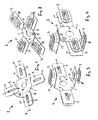
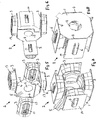
- Ein Ausführungsbeispiel der Erfindung mit vier Spulenträgern ist in den Zeichnungen perspektivisch dargestellt und wird im Folgenden näher beschrieben. Es zeigen:
- Fig. 1
- eine Oberansicht der Spulenträgervorrichtung mit Spulenträgern in einer Ebene,
- Fig. 2
- eine Unteransicht der Spulenträgervorrichtung mit Spulenträgern in einer Ebene,
- Fig. 3
- eine Rückansicht der Spulenträgervorrichtung mit einem Paar nach hinten abgebogenen Spulenträgern mit einem bewickelten Spulenträger,
- Fig. 4
- eine Vorderansicht der Spulenträgervorrichtung mit einem Paar nach hinten abgebogenen Spulenträgern mit einem bewickelten Spulenträger,
- Fig. 5
- eine Rückansicht der Spulenträgervorrichtung mit einem Paar nach hinten abgebogenen Spulenträgern mit einem bewickelten Spulenträger mit vier Bewicklungen bzw. Spulen
- Fig. 6
- eine Rückansicht der Spulenträgervorrichtung mit einem zweiten Paar nach hinten abgebogenen Spulenträgern mit einem bewickelten Spulenträger nach einer 180 Grad Drehung der Spule mit vier Bewicklungen bzw. Spulen
- Fig. 7
- eine Vorderansicht der Spulenträgervorrichtung mit allen Spulenträgern in Arbeitsstellung mit vier Bewicklungen bzw. Spulen
- Fig. 8
- eine Rückansicht der Spulenträgervorrichtung mit allen Spulenträgern in Arbeitsstellung mit vier Bewicklungen bzw. Spulen
- Fig. 9
- eine Rückansicht der Spulenträgervorrichtung nach
Fig. 8 mit Rückschlussring, - Fig. 10
- eine Vorderansicht der Spulenträgervorrichtung nach
Fig. 8 mit Rückschlussring. - Fig.11
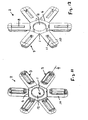
- eine Vorderansicht einer Spulenträgervorrichtung mit sechs Spulenträgern in noch nicht abgewinkelter Stellung,
- Fig. 12
- eine Rückansicht einer Spulenträgervorrichtung mit sechs Spulenträgern in noch nicht abgewinkelter Stellung,
- Fig. 13
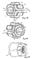
- eine Spulenträgervorrichtung mit nach außen geklappten Spulenträgern, von denen zwei bewickelt sind,
- Fig. 14
- eine Spulenträgervorrichtung mit nach außen geklappten Spulenträgern, die alle bewickelt sind, und
- Fig. 15
- eine Spulenträgervorrichtung mit nach innen geklappten bewickelten Spulenträgern.
- An einem flächigen Trägerelement 1 einer Spulenträgervorrichtung 2 aus Kunststoff sind Spulenträger 3 aus Kunststoff einstückig angeformt, auf der die einzelnen Spulen 13 eines Stators großseriengerecht bewickelt werden. Der Spulenträger 3 mit seinem hohlen Kunststoffkern 8, auf den der Draht der Spule gewickelt wird, ist länglich ausgeführt, d. h. er besitzt eine größere Länge L als Breite B, wobei seine Längsachse 9 radial zum Trägerelement 1 angeordnet ist. Die einzelnen Spulenträger 3 verteilen sich symmetrisch sternförmig um das mittige Kunststoffträgeretement 1 und sind über Scharniere insbesondere Filmscharniere 4 mit diesem verbunden. Auf dem Trägerelement 1, auf das vorzugsweise über MID-Technologie (Model Interconnect Devices) Leiterbahnen aufgebracht sind, wird die elektrische Verschaltung der einzelnen Spulen zueinander hergestellt. Weiterhin dient diese MID Struktur als Träger und Verschaltungsinstrument für alle bzw. Teile der notwendigen elektrischen/elektronischen Bauteile. Zum Anschluss an elektrische Versorgungs- und/oder Regelungsleitungen sind an geeigneten Stellen am Trägerelement 1 elektrische Anschlüsse 5 befestigt. Damit wird das Trägerelement wie eine Leiterplatte verwendet.
- Die Spulenträgervorrichtung 2 besitzt am Trägerelement 1 in der Ebene sternförmig verteilte vier oder mehr Spulenträger 3 als Isolationskörper, auf denen die einzelnen Spulen aufgewickelt werden. Da jeder Spulenträger 3 mit seinem Kunststoffkern 8, auf dem die Wicklungen liegen, eine längliche Form aufweist und seine Längsachse 9 radial zur Mitte der Vorrichtung und des Trägerelements 1 angeordnet ist, ist auch die Ausnehmung 11 von länglicher Form und im noch nicht abgebogenen Zustand radial angeordnet. Der Spulenträger 9 bildet eine Außenplatte 10 mit einer mittigen Öffnung 12 in ihr und im Kern 8. Die Außenplatte 10 liegt in der Ebene des Trägerelements 1 und ist über das Filmscharnier mit dem Trägerelement 1 verbunden.
- Abhängig vom Wickelverfahren der zu bewickelnden Spulenträger 3 in der Ebene des Trägerelements 1 (Flyer, Nadelwickler) wird die Vorrichtung 2 um einen bestimmten Winkel im Werkzeug gedreht (Linearwickler). Aus Gründen der Unwucht, ist es von Vorteil, die einander gegenüberliegenden Spulenträger 3 symmetrisch umzubiegen. Nach dem Bewickeln eines Spulenträgers 3 wird der Draht in dafür vorgesehene Führungsbahnen direkt zum gegenüberliegenden Spulenträger 3 weitergeleitet. Der Anfang und das Ende der Spulen werden mit der MID Struktur leitend verbunden. Zum Kontaktieren der Wicklungsenden mit der MID Struktur bieten sich alle bekannten Kontaktarten wie Schneid-Klemm-Technik, Löten, Schweißen, etc. an. Nach dem Bewickeln aller Spulenträger 3 werden diese in ihre endgültige Position gekippt bzw. umgebogen und mit dem metallischen Rückschlussring verbunden.
- Die zu bewickelnde Spulenträgervorrichtung 2 wird in ihrer Symmetrieachse mit einer drehbaren Vorrichtung des Wickelwerkzeuges befestigt. Am Rand des Spulenträgers 3 am Übergang zur zentralen MID Struktur wird der zu bewickelnde Spulenträger 3, bzw. aus Symmetriegründen bei hohen Wickelgeschwindigkeiten die gegenüberliegenden bzw. alle Spulenträger, über ein Filmscharnier 4 um einen definierten Winkel in eine geeignete Wickellage mittels des Wickelwerkzeuges gedreht und festgehalten.
In dieser Lage wird der Spulenträger 3 fixiert und mittels eines Flyers, Nadelwicklers bzw. eines Linearwicklers bewickelt. Nach Fertigstellung einer Spule wird die Vorrichtung 2 im Werkzeug derart um ihre Symmetrieachse gedreht, dass der Draht über vorgesehene Drahtführungen zum vorzugsweise gegenüberliegenden Spulenträger 3 hingeleitet wird, um diesen zu bewickeln. Somit ist keine separate Kontaktbrücke zwischen den kurzgeschlossenen Wicklungen erforderlich. - Am Anfang und Ende der Spulen sind Kontaktstellen an der MID Struktur des Trägerelements 1 vorgesehen. Diese dienen zur Kontaktierung zwischen Wicklungsenden und MID Leiterbahn. Die notwendige Kontaktierung wird vorzugsweise schon während des Wickelprozesses realisiert. Somit wird zum Abschluss eine bewickelte Spulenträgervorrichtung 2 mit Elektronik erhalten, die abschließend elektrisch bzw. elektronisch getestet wird. Nach dem Bewickeln aller Spulenträger 3 werden die einzelnen Polschuhe 6 in die Ausnehmungen 11 der Spulenträger 3 geschoben, die Spulenträger in ihre endgültige Lage gedreht und mit dem Rückschlussring 7 komplettiert.
- Im Zentrum zwischen den Spulenträgern 3 befindet sich auf dem Trägerelement 1 eine MID Struktur, um die für den Betrieb des Motors notwendige Elektrik/Elektronik, oder Teile dieser funktionsgerecht aufzunehmen. Diese MID Struktur ist je nach Anwendungsfall für Nieder- bzw. Hochspannungsversorgung der Spulen verschieden ausgeführt.
- Die zentrale Verschaltungsgeometrie des Trägerelements 1 beinhaltet auch den Netzanschluss des Motors zur Stromversorgung, sowie den elektrischen Anschluss für eine Steuerungs- bzw. Regelungsleitung. Ggf. werden alle Anschlussleitungen in einer Steckerverbindung vereinigt, die vorzugsweise am Rand des Trägerelements angeordnet ist.
- Der oben beschriebene Stator mit Elektronik und elektrischem Anschluss wird vorzugsweise mittels eines Kunststoffs umspritzt. Zum Abschluss steht eine Statorbaugruppe zur Verfügung, die mit der Rotorbaugruppe, dem Motoreninsbesondere Pumpengehäuse und ggf. mit weiteren Elektronikmodulen schnell und sicher zu einem Motor insbesondere zu einer Motorpumpe montiert wird.
- Im Ausführungsbeispiel sind vier Spulenträger 3 punktsymmetrisch um das mittige Trägerelement 1 angeordnet, so dass die Längsachsen 9 der Spulenträger 3 im noch nicht abgebogenen flachen Zustand der Vorrichtung 2 miteinander Winkel α von 90 Grad bilden. Stattdessen können aber auch sechs, acht oder mehr Spulenträger 3 am mittigen Trägerelement 1 angeformt und punktsymmetrisch angeordnet sein, wobei die Winkel α zwischen den Spulenträgern 3 bzw. deren Längsachsen 9 wiederum gleich groß sind.
- Ferner können die Scharniere 4 eine Schnappverbindung aufweisen.
- Im Folgenden wird die Funktionsweise einer komplexen automatischen Linearwickelmaschine für die Großserienfertigung beschrieben. Bei kleineren Stückzahlen können einzelne Arbeitsschritte manuell ausgeführt werden.
- In einem ersten Arbeitsschritt werden mittels eines Roboters die Spulenträger 3 (Wicklungsträger) mit Polschuhen 15 bestückt und dem Wickelautomaten derart übergeben, dass die zu bewickelnden Spulenträger mit ihren Polschuhen 15 nach außen, mit ihrer Längsachse 9 parallel zur Mittelachse, gerichtet sind. Die Polschuhe 15 besitzen für die Befestigung mit dem Rückschlussring 17 Kontaktgeometrien 18 z. B. Schwalbenschwänze. Diese sind bei der zu bewickelnden Spulenträgervorrichtung 1 zum Zentrum des Trägerelements 1 gerichtet und dienen zur Zentrierung und Befestigung der Spulenträgervorrichtung 1 mit der Wickelmaschine.
- Nach der Bestückung der Wickelmaschine mit einer Spulenträgervorrichtung 1 wird diese um die Drehachse A in die Wickelposition geschwenkt. An der Spulenträgervorrichtung 1 sind Kontakte angebracht, die zur elektrischen Verbindung der Spulen mit der Elektrik/Elektronik des Motors dienen. Der Anfang des Wickeldrahtes wird im nächsten Arbeitsschritt mit dem entsprechenden Kontakt kontaktiert. Dies kann z.B. eine Schweißung, Bondung, Lötung, Schneid-Klemm-Technik, usw. sein. Anschließend wird die erste Spule gewickelt durch Bewickeln des Spulenträgers 3, wobei die Spulenträgervorrichtung 1 um die Drehachse A rotiert.
- Nach Fertigstellung der ersten Spule wird die Spulenträgervorrichtung 1 um ihre eigene Symmetrieachse B gedreht, bis sich der nächste zu bewickelnde Spulenträger 3 in der Wickelposition befindet. Dabei legt sich der Wickeldraht vom Ende der ersten Spule zum Anfang der zweiten Spule, um eine an der Spulenträgervorrichtung 1 bzw. an dem Spulenträger 3 angeformte Drahtführung 15 und stellt einen elektrischen Kurzschluss zwischen den beiden Spulen her. Die Bewicklung der zweiten Spule verläuft analog der ersten. Nach Fertigstellung der zweiten Spule wird das Drahtende analog dem Drahtanfang an der ersten Spule mit einem dafür vorgesehenen Kontakt leitend verbunden. Die weiteren Spulenpaare werden anschließend analog dem ersten Spulenpaar hergestellt. Alternativ können aber auch stets zwei diametral gegenüberliegende Spulenträger gleichzeitig bewickelt werden.
- Nach Abschluss des Wickelprozesses wird die Spulenträgervorrichtung 1 an eine weitere Arbeitsstation übergeben. Dabei werden die bewickelten Spulenträger 3 um die am Trägerelement 1 angeformten Scharniere so weit gedreht, bis diese ihre endgültige Einbauposition erreicht haben und der Rückschlussring 17 aufgeschoben werden kann. Anschließend wird der komplette Stator elektrisch geprüft und zur weiteren Montage an eine folgende Arbeitsstation übergeben.
- Das Wickelverfahren mit einem Flyer - Wickelautomat geschieht analog dem Verfahren als Linearwickler. Jedoch dient die Drehachse A nur zur Bestückung des Wickelautomats mit Spulenträgern. Im Gegensatz zum Linearwickler dreht sich der Draht um die Spule und nicht die Spule um den Draht.
Claims (17)
- Spulenträgervorrichtung (2) für eine elektrische Maschine insbesondere für einen Elektromotor mit Spulenträgern (3) aus Kunststoff, auf denen Spulen des Stators wickelbar sind, dadurch gekennzeichnet, dass die Spulenträger (3) über Scharniere insbesondere Filmscharniere (4) am äußeren Rand eines mittigen Kunststoff-Trägerelements (1) angelenkt insbesondere angeformt sind.
- Spulenträgervorrichtung nach Anspruch 1, dadurch gekennzeichn et, dass mindestens vier Spulenträger (3) am insbesondere flächigen Trägerelement (1) im noch nicht abgebogenen Zustand radial und sternförmig insbesondere punktsymmetrisch befestigt sind.
- Spulenträgervorrichtung nach Anspruch 1 oder 2, dadurch gekennzeichnet, dass die Spulenträger (3) mit ihrem Kunststoff-Spulenträgerkern (8) länglich ausgeführt sind, wobei die Längsachse (9) der Spulenträger (3) im noch nicht abgebogenen Zustand radial zum Trägerelement (1) angeordnet ist.
- Spulenträgervorrichtung nach einem der vorherigen Anspruch, dadurch gekennzeichnet, dass die Spulenträger (3) aus der Ebene des Trägerelements (1) heraus um das Filmscharnier (4) zur Vorder- und/oder Rückseite des Trägerelements (1) biegbar sind.
- Spulenträgervorrichtung nach Anspruch 4, dadurch gekennzeichnet, dass die Spulenträger (3) in der umgebogenen abgewinkelten Stellung zueinander parallel und rechtwinklig zum Trägerelement (1) stehen.
- Spulenträgervorrichtung nach einem der vorherigen Ansprüche, dadurch gekennzeichnet, dass nach dem Bewickeln aller Spulenträger (3) diese alle zu einer Seite des Trägerelements (1) rechtwinklig derart in die Arbeitsstellung umgebogen sind, dass die Spulen den Rotor und insbesondere ein Spaltrohr einer Spaltrohr-Motorpumpe außen umgeben.
- Spulenträgervorrichtung nach einem der vorherigen Ansprüche, dadurch gekennzeichnet, dass jeder Spulenträger (3) eine rückwärtige Außenplatte (10) aus Kunststoff aufweist, die über das Filmscharnier (4) mit dem Trägerelement (1) verbunden und an der der Kunststoffkern (8) des Spulenträgers (3) angeformt ist.
- Spulenträgervorrichtung nach Anspruch 7, dadurch gekennzeichnet, dass in der nicht abgewinkelten Stellung der Spulenträger (3) die Außenplatten (10) insbesondere im Wesentlichen in der Ebene des Trägerelements (1) liegen.
- Spulenträgervorrichtung nach Anspruch 7 oder 8, dadurch gekennzeichnet, dass in der Außenplatte (10) und dem Kunststoffkern (8) eine Ausnehmung (11) für den Polschuh (6) ist.
- Spulenträgervorrichtung nach einem der vorherigen Ansprüche, dadurch gekennzeichnet, dass im Trägerelement (1) eine mittige Öffnung (12) für die Maschinenwelle ist.
- Spulenträgervorrichtung nach einem der vorherigen Ansprüche, dadurch gekennzeichnet, dass das Scharnier eine Schnappverbindung aufweist oder von einer Schnappverbindung gebildet ist.
- Verfahren zum Bewickeln einer Spulenträgenrorrichtung nach einem der vorherigen Ansprüche, dadurch gekennzeichnet, dass nach Herstellung der Spulenträgervorrichtung (2) diese in einen Wickelautomat in der Weise eingesetzt wird, dass zumindest ein Spulenträger (3) gegenüber dem Trägerelement (1) um das Scharnier vorzugsweise um 90 Grad umgebogen wird, wobei der zu bewickelnde Kern (8) des Spulenträgers (3) nach außen ragt, und danach der Spulenträger (3) und dessen Kern (8) bewickelt wird.
- Verfahren nach Anspruch 12, dadurch gekennzeichnet, dass vor dem Bewickeln die Polschuhe (15) in die Ausnehmungen (11) der Spulenträger eingesetzt werden.
- Verfahren nach Anspruch 12 oder 13, dadurch gekennzeichnet, dass nach dem Bewickeln eines oder zweier einander diametral gegenüberliegender Spulenträger (3) die Spulenträgervorrichtung (2) um einen Winkel (β) gedreht wird, so dass danach ein nächster oder zwei nächste diametral gegenüberliegende Spulenträger (3) in der Bewicklungsstellung liegen, die um 90 Grad nach außen umgebogen worden sind.
- Verfahren nach Anspruch 14, dadurch gekennzeichnet, dass während des Verdrehens der Spulenträgervorrichtung (2) der Wickeldraht von einer bewickelten Spule zum nächsten Spulenträger (3) geführt wird.
- Verfahren nach Anspruch 15, dadurch gekennzeichnet, dass der Wickeldraht um eine Drahtführung (15) des Trägerelements (1) gelegt wird.
- Verfahren nach einem der Ansprüche 12 bis 16 dadurch gekennzeichnet, dass nach dem Bewickeln eines, zwei oder mehrerer Spulenträger (3) die bewickelten Spulenträger (3) um 180 Grad nach innen um das jeweilige Scharnier (4) geschwenkt werden.
Applications Claiming Priority (2)
| Application Number | Priority Date | Filing Date | Title |
|---|---|---|---|
| DE102006041715A DE102006041715A1 (de) | 2006-09-06 | 2006-09-06 | Spulenträgervorrichtung |
| PCT/EP2007/006311 WO2008028536A1 (de) | 2006-09-06 | 2007-07-17 | Spulenträgervorrichtung |
Publications (2)
| Publication Number | Publication Date |
|---|---|
| EP2059991A1 EP2059991A1 (de) | 2009-05-20 |
| EP2059991B1 true EP2059991B1 (de) | 2009-12-16 |
Family
ID=38617919
Family Applications (1)
| Application Number | Title | Priority Date | Filing Date |
|---|---|---|---|
| EP07786111A Active EP2059991B1 (de) | 2006-09-06 | 2007-07-17 | Spulenträgervorrichtung |
Country Status (6)
| Country | Link |
|---|---|
| US (1) | US8196286B2 (de) |
| EP (1) | EP2059991B1 (de) |
| CN (1) | CN101512873B (de) |
| AT (1) | ATE452455T1 (de) |
| DE (2) | DE102006041715A1 (de) |
| WO (1) | WO2008028536A1 (de) |
Cited By (1)
| Publication number | Priority date | Publication date | Assignee | Title |
|---|---|---|---|---|
| DE102011008816A1 (de) | 2011-01-19 | 2012-07-19 | Wilo Se | Fertigung eines Elektromotorenstators |
Families Citing this family (10)
| Publication number | Priority date | Publication date | Assignee | Title |
|---|---|---|---|---|
| DE102008060896B4 (de) | 2008-08-11 | 2017-11-02 | Hanning Elektro-Werke Gmbh & Co. Kg | Spulentragvorrichtung |
| DE102009045655A1 (de) * | 2009-10-14 | 2011-04-21 | Robert Bosch Gmbh | Vollintegriertes Gebläsemodul |
| WO2011098247A1 (de) * | 2010-02-09 | 2011-08-18 | Richard Halm | Vorrichtung zum wandeln von elektrischer in mechanische energie und/oder umgekehrt, wickelkörper für eine solche vorrichtung und verfahren zum herstellen einer solchen vorrichtung |
| DE102010026527A1 (de) | 2010-06-25 | 2012-03-29 | Aumann Gmbh | Verfahren und Vorrichtung zur Bewicklung von Polsternen, insbesondere für Statoren von Innenläufermotoren |
| DE102010041274A1 (de) * | 2010-09-23 | 2012-03-29 | Siemens Aktiengesellschaft | Verfahren zur Herstellung eines Ständers und entspr chender Ständer für einen Elektromotor |
| CN103133776A (zh) * | 2013-03-06 | 2013-06-05 | 太仓市协诚金属制品有限公司 | 一种具有防护板的车间缆线架 |
| EP2824811A1 (de) * | 2013-07-11 | 2015-01-14 | Siemens Aktiengesellschaft | Durchgehende, auf Spulenträger gewickelte Statorwicklung |
| DE102014115544A1 (de) * | 2014-10-27 | 2016-04-28 | BROSE SCHLIEßSYSTEME GMBH & CO. KG | Spulenträgeranordnung |
| DE102017200314A1 (de) * | 2017-01-11 | 2018-07-12 | Robert Bosch Gmbh | Elektrische Maschine mit einem Stator und ein Verfahren für den Stator |
| FR3075505B1 (fr) | 2017-12-18 | 2022-03-11 | Whylot Sas | Stator de moteur ou generatrice electromagnetique avec support individuel de bobinage encliquete sur une dent associee |
Family Cites Families (6)
| Publication number | Priority date | Publication date | Assignee | Title |
|---|---|---|---|---|
| FR2384376A1 (fr) * | 1977-03-16 | 1978-10-13 | Roshardt Didier | Moteurs a poles fendus |
| DE2843006C2 (de) * | 1978-10-03 | 1983-06-23 | Robert Bosch Gmbh, 7000 Stuttgart | Stator für elektrische Maschinen |
| JPS55133520A (en) * | 1979-04-04 | 1980-10-17 | Sumida Denki Kk | Automatic coil winder |
| JP3399295B2 (ja) * | 1997-04-25 | 2003-04-21 | 日本ビクター株式会社 | コンバーゼンス補正装置 |
| US6081059A (en) * | 1999-04-21 | 2000-06-27 | Hsu; Chun-Pu | Outer-rotor electric motor having inner-stator formed by concentrically wrapping flattened stator elements on stator core |
| EP1283582B1 (de) * | 2001-08-09 | 2005-01-19 | Siemens Aktiengesellschaft | Anordnung innen gekühlter elektrischer Leiter, insbesondere für einen Generatorläufer |
-
2006
- 2006-09-06 DE DE102006041715A patent/DE102006041715A1/de not_active Withdrawn
-
2007
- 2007-07-17 AT AT07786111T patent/ATE452455T1/de active
- 2007-07-17 CN CN2007800330071A patent/CN101512873B/zh active Active
- 2007-07-17 WO PCT/EP2007/006311 patent/WO2008028536A1/de active Application Filing
- 2007-07-17 US US12/440,091 patent/US8196286B2/en active Active
- 2007-07-17 DE DE502007002367T patent/DE502007002367D1/de active Active
- 2007-07-17 EP EP07786111A patent/EP2059991B1/de active Active
Cited By (3)
| Publication number | Priority date | Publication date | Assignee | Title |
|---|---|---|---|---|
| DE102011008816A1 (de) | 2011-01-19 | 2012-07-19 | Wilo Se | Fertigung eines Elektromotorenstators |
| EP2479869A2 (de) | 2011-01-19 | 2012-07-25 | Wilo Se | Fertigung eines Elektromotorenstators |
| EP2479869A3 (de) * | 2011-01-19 | 2017-04-12 | Wilo Se | Fertigung eines Elektromotorenstators |
Also Published As
| Publication number | Publication date |
|---|---|
| DE102006041715A1 (de) | 2008-03-27 |
| ATE452455T1 (de) | 2010-01-15 |
| US8196286B2 (en) | 2012-06-12 |
| US20100077601A1 (en) | 2010-04-01 |
| EP2059991A1 (de) | 2009-05-20 |
| WO2008028536A1 (de) | 2008-03-13 |
| DE502007002367D1 (de) | 2010-01-28 |
| CN101512873A (zh) | 2009-08-19 |
| WO2008028536A8 (de) | 2009-05-14 |
| CN101512873B (zh) | 2012-01-25 |
Similar Documents
| Publication | Publication Date | Title |
|---|---|---|
| EP2059991B1 (de) | Spulenträgervorrichtung | |
| EP1810388B1 (de) | Elektromotor | |
| EP2082472B1 (de) | Elektromotor | |
| DE112005003615B4 (de) | Herstellungsverfahren für einen Drehmotor | |
| EP2584672B1 (de) | Gehäuseteil für eine elektrische Maschine | |
| DE102005001705A1 (de) | Verfahren zur Herstellung von Ankern, Verfahren zur Herstellung von Elektromotoren sowie Anker | |
| EP3078099B1 (de) | Stator für einen elektronisch kommutierten gleichstrommotor | |
| DE102012113095B4 (de) | Bürstenloser Motor | |
| DE102009016990A1 (de) | Stator, Motor und Verfahren zur Herstellung eines Stators | |
| EP2520005B1 (de) | Herstellungsverfahren eines stators aus segmenten einschliesslich des bewickelns und zugehöriger stator | |
| DE102012216542A1 (de) | Verbindungsmodul für eine statoranordnung mit stabwicklungen und verfahren zum herstellen einer statoranordnung mit stabwicklungen | |
| DE10152499A1 (de) | Elektromotor | |
| DE102009038258A1 (de) | Bürstenträger eines Motors | |
| WO2019072477A1 (de) | Verschaltungsvorrichtung für eine elektrische maschine | |
| WO2020015855A1 (de) | Elektromotor mit einer verschaltungseinheit und verfahren zur herstellung eines elektromotors mit einer verschaltungseinheit | |
| EP1024581B1 (de) | Kontaktierung von Motorwicklungen | |
| WO2012175485A2 (de) | Schaltungsträger für die verkabelung der zahnspulenwicklungen eines stators einer elektrischen maschine und bausatz, enthaltend einen solchen schaltungsträger | |
| DE3639004C2 (de) | ||
| EP3963694A1 (de) | Stator und verfahren zur herstellung eines stators | |
| DE102018116930A1 (de) | Stator für eine Gleichstrommaschine und Verfahren zum Herstellen eines solchen Stators | |
| DE10231092A1 (de) | Außenläufermotor | |
| WO2020173913A1 (de) | Elektrische kontaktierung von statoranschlüssen auf einer leiterplatte mittels horizontal ausgerichteten schneidklemmkontakten | |
| EP3824529A1 (de) | Elektromotor mit einer verschaltungseinheit und verfahren zur herstellung eines elektromotors mit einer verschaltungseinheit | |
| EP1603216B1 (de) | Bürstenloser Elektromotor und Verfahren zur Herstellung desselben | |
| WO2013098111A2 (de) | Verfahren zum herstellen einer maschinenkomponente für eine elektrische maschine sowie eine maschinenkomponente |
Legal Events
| Date | Code | Title | Description |
|---|---|---|---|
| PUAI | Public reference made under article 153(3) epc to a published international application that has entered the european phase |
Free format text: ORIGINAL CODE: 0009012 |
|
| 17P | Request for examination filed |
Effective date: 20090210 |
|
| AK | Designated contracting states |
Kind code of ref document: A1 Designated state(s): AT BE BG CH CY CZ DE DK EE ES FI FR GB GR HU IE IS IT LI LT LU LV MC MT NL PL PT RO SE SI SK TR |
|
| AX | Request for extension of the european patent |
Extension state: AL BA HR MK RS |
|
| RIN1 | Information on inventor provided before grant (corrected) |
Inventor name: TRELOW, GUENTER Inventor name: MATERNE, THOMAS Inventor name: HOHEISEL, STEPHAN Inventor name: DREIHAUS, UWE |
|
| GRAP | Despatch of communication of intention to grant a patent |
Free format text: ORIGINAL CODE: EPIDOSNIGR1 |
|
| RIN1 | Information on inventor provided before grant (corrected) |
Inventor name: STRELOW, GUENTER Inventor name: DREIHAUS, UWE Inventor name: HOHEISEL, STEPHAN Inventor name: MATERNE, THOMAS |
|
| GRAS | Grant fee paid |
Free format text: ORIGINAL CODE: EPIDOSNIGR3 |
|
| GRAA | (expected) grant |
Free format text: ORIGINAL CODE: 0009210 |
|
| RAP1 | Party data changed (applicant data changed or rights of an application transferred) |
Owner name: WILO SE |
|
| AK | Designated contracting states |
Kind code of ref document: B1 Designated state(s): AT BE BG CH CY CZ DE DK EE ES FI FR GB GR HU IE IS IT LI LT LU LV MC MT NL PL PT RO SE SI SK TR |
|
| REG | Reference to a national code |
Ref country code: GB Ref legal event code: FG4D Free format text: NOT ENGLISH |
|
| REG | Reference to a national code |
Ref country code: CH Ref legal event code: EP |
|
| REG | Reference to a national code |
Ref country code: IE Ref legal event code: FG4D |
|
| REF | Corresponds to: |
Ref document number: 502007002367 Country of ref document: DE Date of ref document: 20100128 Kind code of ref document: P |
|
| REG | Reference to a national code |
Ref country code: NL Ref legal event code: VDEP Effective date: 20091216 |
|
| PG25 | Lapsed in a contracting state [announced via postgrant information from national office to epo] |
Ref country code: LT Free format text: LAPSE BECAUSE OF FAILURE TO SUBMIT A TRANSLATION OF THE DESCRIPTION OR TO PAY THE FEE WITHIN THE PRESCRIBED TIME-LIMIT Effective date: 20091216 Ref country code: FI Free format text: LAPSE BECAUSE OF FAILURE TO SUBMIT A TRANSLATION OF THE DESCRIPTION OR TO PAY THE FEE WITHIN THE PRESCRIBED TIME-LIMIT Effective date: 20091216 Ref country code: SE Free format text: LAPSE BECAUSE OF FAILURE TO SUBMIT A TRANSLATION OF THE DESCRIPTION OR TO PAY THE FEE WITHIN THE PRESCRIBED TIME-LIMIT Effective date: 20091216 |
|
| LTIE | Lt: invalidation of european patent or patent extension |
Effective date: 20091216 |
|
| PG25 | Lapsed in a contracting state [announced via postgrant information from national office to epo] |
Ref country code: LV Free format text: LAPSE BECAUSE OF FAILURE TO SUBMIT A TRANSLATION OF THE DESCRIPTION OR TO PAY THE FEE WITHIN THE PRESCRIBED TIME-LIMIT Effective date: 20091216 Ref country code: PL Free format text: LAPSE BECAUSE OF FAILURE TO SUBMIT A TRANSLATION OF THE DESCRIPTION OR TO PAY THE FEE WITHIN THE PRESCRIBED TIME-LIMIT Effective date: 20091216 Ref country code: SI Free format text: LAPSE BECAUSE OF FAILURE TO SUBMIT A TRANSLATION OF THE DESCRIPTION OR TO PAY THE FEE WITHIN THE PRESCRIBED TIME-LIMIT Effective date: 20091216 |
|
| REG | Reference to a national code |
Ref country code: IE Ref legal event code: FD4D |
|
| PG25 | Lapsed in a contracting state [announced via postgrant information from national office to epo] |
Ref country code: PT Free format text: LAPSE BECAUSE OF FAILURE TO SUBMIT A TRANSLATION OF THE DESCRIPTION OR TO PAY THE FEE WITHIN THE PRESCRIBED TIME-LIMIT Effective date: 20100416 Ref country code: NL Free format text: LAPSE BECAUSE OF FAILURE TO SUBMIT A TRANSLATION OF THE DESCRIPTION OR TO PAY THE FEE WITHIN THE PRESCRIBED TIME-LIMIT Effective date: 20091216 Ref country code: IS Free format text: LAPSE BECAUSE OF FAILURE TO SUBMIT A TRANSLATION OF THE DESCRIPTION OR TO PAY THE FEE WITHIN THE PRESCRIBED TIME-LIMIT Effective date: 20100416 Ref country code: BG Free format text: LAPSE BECAUSE OF FAILURE TO SUBMIT A TRANSLATION OF THE DESCRIPTION OR TO PAY THE FEE WITHIN THE PRESCRIBED TIME-LIMIT Effective date: 20100316 Ref country code: RO Free format text: LAPSE BECAUSE OF FAILURE TO SUBMIT A TRANSLATION OF THE DESCRIPTION OR TO PAY THE FEE WITHIN THE PRESCRIBED TIME-LIMIT Effective date: 20091216 Ref country code: ES Free format text: LAPSE BECAUSE OF FAILURE TO SUBMIT A TRANSLATION OF THE DESCRIPTION OR TO PAY THE FEE WITHIN THE PRESCRIBED TIME-LIMIT Effective date: 20100327 Ref country code: IE Free format text: LAPSE BECAUSE OF FAILURE TO SUBMIT A TRANSLATION OF THE DESCRIPTION OR TO PAY THE FEE WITHIN THE PRESCRIBED TIME-LIMIT Effective date: 20091216 Ref country code: EE Free format text: LAPSE BECAUSE OF FAILURE TO SUBMIT A TRANSLATION OF THE DESCRIPTION OR TO PAY THE FEE WITHIN THE PRESCRIBED TIME-LIMIT Effective date: 20091216 |
|
| PG25 | Lapsed in a contracting state [announced via postgrant information from national office to epo] |
Ref country code: SK Free format text: LAPSE BECAUSE OF FAILURE TO SUBMIT A TRANSLATION OF THE DESCRIPTION OR TO PAY THE FEE WITHIN THE PRESCRIBED TIME-LIMIT Effective date: 20091216 Ref country code: CZ Free format text: LAPSE BECAUSE OF FAILURE TO SUBMIT A TRANSLATION OF THE DESCRIPTION OR TO PAY THE FEE WITHIN THE PRESCRIBED TIME-LIMIT Effective date: 20091216 |
|
| PLBE | No opposition filed within time limit |
Free format text: ORIGINAL CODE: 0009261 |
|
| STAA | Information on the status of an ep patent application or granted ep patent |
Free format text: STATUS: NO OPPOSITION FILED WITHIN TIME LIMIT |
|
| PG25 | Lapsed in a contracting state [announced via postgrant information from national office to epo] |
Ref country code: CY Free format text: LAPSE BECAUSE OF FAILURE TO SUBMIT A TRANSLATION OF THE DESCRIPTION OR TO PAY THE FEE WITHIN THE PRESCRIBED TIME-LIMIT Effective date: 20091216 Ref country code: GR Free format text: LAPSE BECAUSE OF FAILURE TO SUBMIT A TRANSLATION OF THE DESCRIPTION OR TO PAY THE FEE WITHIN THE PRESCRIBED TIME-LIMIT Effective date: 20100317 |
|
| 26N | No opposition filed |
Effective date: 20100917 |
|
| BERE | Be: lapsed |
Owner name: WILO SE Effective date: 20100731 |
|
| PG25 | Lapsed in a contracting state [announced via postgrant information from national office to epo] |
Ref country code: DK Free format text: LAPSE BECAUSE OF FAILURE TO SUBMIT A TRANSLATION OF THE DESCRIPTION OR TO PAY THE FEE WITHIN THE PRESCRIBED TIME-LIMIT Effective date: 20091216 |
|
| PG25 | Lapsed in a contracting state [announced via postgrant information from national office to epo] |
Ref country code: MC Free format text: LAPSE BECAUSE OF NON-PAYMENT OF DUE FEES Effective date: 20100731 |
|
| PG25 | Lapsed in a contracting state [announced via postgrant information from national office to epo] |
Ref country code: BE Free format text: LAPSE BECAUSE OF NON-PAYMENT OF DUE FEES Effective date: 20100731 |
|
| PG25 | Lapsed in a contracting state [announced via postgrant information from national office to epo] |
Ref country code: MT Free format text: LAPSE BECAUSE OF FAILURE TO SUBMIT A TRANSLATION OF THE DESCRIPTION OR TO PAY THE FEE WITHIN THE PRESCRIBED TIME-LIMIT Effective date: 20091216 |
|
| REG | Reference to a national code |
Ref country code: CH Ref legal event code: PL |
|
| PG25 | Lapsed in a contracting state [announced via postgrant information from national office to epo] |
Ref country code: LI Free format text: LAPSE BECAUSE OF NON-PAYMENT OF DUE FEES Effective date: 20110731 Ref country code: CH Free format text: LAPSE BECAUSE OF NON-PAYMENT OF DUE FEES Effective date: 20110731 |
|
| PG25 | Lapsed in a contracting state [announced via postgrant information from national office to epo] |
Ref country code: HU Free format text: LAPSE BECAUSE OF FAILURE TO SUBMIT A TRANSLATION OF THE DESCRIPTION OR TO PAY THE FEE WITHIN THE PRESCRIBED TIME-LIMIT Effective date: 20100617 Ref country code: LU Free format text: LAPSE BECAUSE OF NON-PAYMENT OF DUE FEES Effective date: 20100717 |
|
| PG25 | Lapsed in a contracting state [announced via postgrant information from national office to epo] |
Ref country code: TR Free format text: LAPSE BECAUSE OF FAILURE TO SUBMIT A TRANSLATION OF THE DESCRIPTION OR TO PAY THE FEE WITHIN THE PRESCRIBED TIME-LIMIT Effective date: 20091216 |
|
| REG | Reference to a national code |
Ref country code: AT Ref legal event code: MM01 Ref document number: 452455 Country of ref document: AT Kind code of ref document: T Effective date: 20120731 |
|
| PG25 | Lapsed in a contracting state [announced via postgrant information from national office to epo] |
Ref country code: AT Free format text: LAPSE BECAUSE OF NON-PAYMENT OF DUE FEES Effective date: 20120731 |
|
| PGFP | Annual fee paid to national office [announced via postgrant information from national office to epo] |
Ref country code: GB Payment date: 20140716 Year of fee payment: 8 |
|
| GBPC | Gb: european patent ceased through non-payment of renewal fee |
Effective date: 20150717 |
|
| PG25 | Lapsed in a contracting state [announced via postgrant information from national office to epo] |
Ref country code: GB Free format text: LAPSE BECAUSE OF NON-PAYMENT OF DUE FEES Effective date: 20150717 |
|
| REG | Reference to a national code |
Ref country code: FR Ref legal event code: PLFP Year of fee payment: 10 |
|
| REG | Reference to a national code |
Ref country code: FR Ref legal event code: PLFP Year of fee payment: 11 |
|
| REG | Reference to a national code |
Ref country code: FR Ref legal event code: PLFP Year of fee payment: 12 |
|
| P01 | Opt-out of the competence of the unified patent court (upc) registered |
Effective date: 20230615 |
|
| PGFP | Annual fee paid to national office [announced via postgrant information from national office to epo] |
Ref country code: IT Payment date: 20230620 Year of fee payment: 17 Ref country code: FR Payment date: 20230621 Year of fee payment: 17 |
|
| PGFP | Annual fee paid to national office [announced via postgrant information from national office to epo] |
Ref country code: DE Payment date: 20230620 Year of fee payment: 17 |