EP2399692A1 - Dauergießform zum Gießen von Gussstücken aus einer Metallschmelze - Google Patents
Dauergießform zum Gießen von Gussstücken aus einer Metallschmelze Download PDFInfo
- Publication number
- EP2399692A1 EP2399692A1 EP11171279A EP11171279A EP2399692A1 EP 2399692 A1 EP2399692 A1 EP 2399692A1 EP 11171279 A EP11171279 A EP 11171279A EP 11171279 A EP11171279 A EP 11171279A EP 2399692 A1 EP2399692 A1 EP 2399692A1
- Authority
- EP
- European Patent Office
- Prior art keywords
- mold
- permanent
- package
- casting
- continuous casting
- Prior art date
- Legal status (The legal status is an assumption and is not a legal conclusion. Google has not performed a legal analysis and makes no representation as to the accuracy of the status listed.)
- Granted
Links
- 229910052751 metal Inorganic materials 0.000 title claims abstract description 12
- 239000002184 metal Substances 0.000 title claims abstract description 12
- 238000000465 moulding Methods 0.000 title claims description 16
- 238000005266 casting Methods 0.000 claims abstract description 71
- 239000000463 material Substances 0.000 claims abstract description 7
- 238000009749 continuous casting Methods 0.000 claims description 18
- XLYOFNOQVPJJNP-UHFFFAOYSA-N water Substances O XLYOFNOQVPJJNP-UHFFFAOYSA-N 0.000 claims description 8
- 238000002485 combustion reaction Methods 0.000 claims description 7
- 239000011230 binding agent Substances 0.000 claims description 3
- 239000012778 molding material Substances 0.000 claims description 3
- 238000003384 imaging method Methods 0.000 claims description 2
- 239000012634 fragment Substances 0.000 claims 1
- 239000000155 melt Substances 0.000 abstract description 5
- 239000007789 gas Substances 0.000 description 9
- 230000008901 benefit Effects 0.000 description 8
- 238000004519 manufacturing process Methods 0.000 description 7
- 238000003754 machining Methods 0.000 description 5
- 238000013461 design Methods 0.000 description 4
- 229910052782 aluminium Inorganic materials 0.000 description 3
- XAGFODPZIPBFFR-UHFFFAOYSA-N aluminium Chemical compound [Al] XAGFODPZIPBFFR-UHFFFAOYSA-N 0.000 description 3
- 230000002093 peripheral effect Effects 0.000 description 3
- 230000032258 transport Effects 0.000 description 3
- 230000009471 action Effects 0.000 description 2
- 239000000306 component Substances 0.000 description 2
- 239000002131 composite material Substances 0.000 description 2
- 239000008358 core component Substances 0.000 description 2
- 230000010354 integration Effects 0.000 description 2
- 239000003110 molding sand Substances 0.000 description 2
- 238000012545 processing Methods 0.000 description 2
- 229910001018 Cast iron Inorganic materials 0.000 description 1
- 229910000831 Steel Inorganic materials 0.000 description 1
- 238000004891 communication Methods 0.000 description 1
- 238000001816 cooling Methods 0.000 description 1
- 239000012809 cooling fluid Substances 0.000 description 1
- 230000001419 dependent effect Effects 0.000 description 1
- 238000011161 development Methods 0.000 description 1
- 238000005516 engineering process Methods 0.000 description 1
- 238000005304 joining Methods 0.000 description 1
- 238000011031 large-scale manufacturing process Methods 0.000 description 1
- 230000007257 malfunction Effects 0.000 description 1
- 238000005259 measurement Methods 0.000 description 1
- 230000004044 response Effects 0.000 description 1
- 238000007789 sealing Methods 0.000 description 1
- 238000007493 shaping process Methods 0.000 description 1
- 238000007711 solidification Methods 0.000 description 1
- 230000008023 solidification Effects 0.000 description 1
- 239000010959 steel Substances 0.000 description 1
- 230000008646 thermal stress Effects 0.000 description 1
- 239000002912 waste gas Substances 0.000 description 1
Images

Classifications
-
- B—PERFORMING OPERATIONS; TRANSPORTING
- B22—CASTING; POWDER METALLURGY
- B22C—FOUNDRY MOULDING
- B22C9/00—Moulds or cores; Moulding processes
- B22C9/06—Permanent moulds for shaped castings
-
- B—PERFORMING OPERATIONS; TRANSPORTING
- B22—CASTING; POWDER METALLURGY
- B22C—FOUNDRY MOULDING
- B22C9/00—Moulds or cores; Moulding processes
- B22C9/02—Sand moulds or like moulds for shaped castings
-
- B—PERFORMING OPERATIONS; TRANSPORTING
- B22—CASTING; POWDER METALLURGY
- B22C—FOUNDRY MOULDING
- B22C9/00—Moulds or cores; Moulding processes
- B22C9/10—Cores; Manufacture or installation of cores
- B22C9/103—Multipart cores
Definitions
- the invention relates to a permanent casting mold for casting a casting from a molten metal, which is composed of at least two permanent mold parts delimiting the mold cavity of the permanent casting mold from the environment, which remain intact when the casting is removed from the mold.
- Continuous casting molds of this type also known as "casting molds" in technical terminology, are used, for example, in mass production to cast cylinder heads for internal combustion engines from an aluminum melt.
- the object of the invention was to provide a way, a complex shaped component, as it represents a cylinder head with a molded on the type of the above cylinder head design turbocharger housing, reliable in high volumes and cost casting technology to finished.
- a permanent casting mold according to the invention for casting a casting from a molten metal is composed of at least two permanent mold parts which delimit the cavity of the permanent casting mold from the environment.
- the permanent moldings are characterized by the fact that they are not destroyed during removal of the casting, but preserved and can be reused accordingly for many casting runs.
- casting cores or molded parts can also be positioned as usual in a permanent casting mold according to the invention within the mold cavity, which decay into many free-flowing individual parts as a result of targeted mechanical force or the thermal stresses occurring during the casting. Casting cores of this type are required, for example, in permanent casting molds if channels, cavities, etc. are to be formed within the respective casting.
- this mold package consists of a material which breaks when the cast part is completely removed from the mold and surrounds a mold cavity section.
- the mold cavity section surrounded by the mold package is in communication with the mold cavity of the permanent mold, so that melt filled into the mold cavity of the permanent mold passes into the mold cavity section of the mold package and vice versa.
- the permanent casting mold is supplemented by a mold package which, viewed individually, is designed in the manner of a lost casting mold and is newly created for each casting process.
- a mold package which, viewed individually, is designed in the manner of a lost casting mold and is newly created for each casting process.
- the invention combines the advantages of a permanent mold with the advantages of a mold package designed as a lost mold. Since the volume of the functional part respectively imaged by the mold package is small compared to the volume that is imaged in the mold cavity surrounded by the permanent mold parts, the expense to be taken into account for the production of the mold package is also in relation to the advantages resulting from the design according to the invention a mold can be achieved, low.
- the mold package associated parts of the permanent mold and the mold package can be designed so that in the finished composite permanent mold the mold package is applied to an outer surface of the permanent mold.
- a separate seal may be provided for sealing the existing between the permanent mold and the mold package joining gap. This can for example also be arranged so that it acts between the peripheral wall of the opening, which is associated with the mold package, and a corresponding surface of the mold package.
- At least one first mold element and formed on at least one of the Treasureg cashformmaschine a corresponding to the first mold element shaped second mold element may be formed on the mold package, the form-fitting with the mold element of the mold package cooperates.
- the respective shaping elements acting in the manner of core marks can be designed such that they not only define the position of the mold package in relation to the permanent moldings, but also ensure a captive hold of the mold package on the associated permanent moldings.
- the opening of the permanent mold associated with the mold package may contribute to the proper alignment of the mold package when the opening of the permanent mold associated with the mold package widens, at least in sections, starting from the mold cavity of the permanent mold in the direction of the outer surface of the permanent mold.
- the opening is then designed in the manner of a funnel in such a way that the mold package inserted into the opening is automatically aligned during its mounting on the surfaces of the widening sections lying against it.
- the edge region, which surrounds the opening associated with the mold package may be designed tapering at least in sections in the direction of the mold cavity of the permanent mold or in the manner of a throat.
- the mold package forming the functional element to be molded will typically be composed of two or more moldings or mold cores.
- the mold package can map a functional part, which is integrally connected to the cylinder head with finished cast cylinder head and has at least one channel which is connected without interruption with a channel of the cylinder head.
- a functional part may be, for example, the housing or a housing part of a turbocharger.
- the mold package may, for example, moldings, through which the outer shape of the housing or housing part is determined, and mold cores, which image the exhaust passage and an optionally additionally provided cooling fluid channel in the housing.
- the mold package then comprises a first mold core which images a water channel of the functional part connected to the water jacket of the cylinder head to be cast, and a second mold core which images an exhaust gas duct connected to an exhaust pipe of the cylinder head.
- a continuous casting mold which is supplemented according to the invention by a mold package which is made from a mold material which breaks down into many individual parts during removal from the mold, is suitable in particular for producing cast parts from a light metal melt, in particular an aluminum melt, since the use of such light metal melts is particularly advantageous
- Benefit from the chill casting in combination with the benefits of Formvolsses can be used to produce, for example, complex cylinder head designs for internal combustion engines, which on the one hand optimal Function integration and on the other hand, a minimization of production costs.
- At least one molding element may be provided on the casting mold for imaging a first receiving point on the casting.
- a first reception point or several such initial reception points are used in particular in automated machining as a starting point for the measurement of the geometry of the respective casting.
- the Clearage determine the "zero points" for the alignment of the machining tool or the respective workpiece to be machined in the x-, y- and z-direction.
- the portion of the casting shown in the destructible mold package is a special one Machining must be subjected to the particular requirements, for example, in terms of geometry, in particular the correct position positioning of the respective processing sections, provided, it may be useful if an additional mold element is provided on the mold, which at the imaged in the mold package section of Cast part forms an additional Clearageyak.
- This additional initial reception point can form the basis for an additional reference system which is independent of the reference system, which is based on the initial reception generally provided on the casting.
- This possibility proves to be particularly advantageous if an exhaust-gas turbocharger housing is depicted in the mold package, the mounting surface of which and the machined functional geometries for the turbocharger to be assembled require machining performed with extreme precision.
- the permanent mold 1 is mounted on a support plate 2.
- the carrier plate 2 is arranged for example on a transport system, not shown, which transports the permanent mold 1 to a casting station, also not shown here.
- the permanent casting mold 1 is composed of a molded part 3, which is usually made of molding sand, and of several permanent casting moldings, of which the permanent mold parts 4, 5, 6 are visible here.
- the molded part 3 forms the cover, the permanent mold part 4 a first side wall, the permanent mold part 6 a second side wall and the permanent mold part 5 a bottom of the permanent mold 1.
- the permanent mold parts of the permanent mold 1 can be made in a known manner from a suitable steel, the so high temperature and wear resistant is that the permanent moldings can be reused for a large number of casting operations.
- the permanent mold parts of the permanent mold 1 define a mold cavity 7 of the permanent mold 1 with respect to the environment U and have on their the mold cavity 7 associated side mold elements 8.9, through which the outer shape of the cylinder head to be cast is displayed.
- the mold core 12 which is arranged at a distance between the mold cores 10, 11, forms an exhaust gas duct integrated into the cylinder head to be cast, by means of which, in accordance with FIG EP 2 143 926 A1 described development, the exhaust gas outlets of the cylinder head to be cast are performed together to an outlet opening.
- the one side wall of the permanent mold 1 forming permanent mold part 5 is formed starting from the edge, which is assigned to the lid of the permanent mold 1 forming mold part 3, an opening 13 which extends in the direction of the opposite edge.
- the mandrels 10,11,12 are each designed so that they end at the opening 13 and project into the opening 13 of the permanent mold 1.
- the width of the opening 13 is at the same time dimensioned so that it receives a projection 20 of a mold package 21, which is arranged on the outside of the permanent mold part 6.
- This projection 20 of the mold package 21 fills the opening 13 of the permanent mold 1 completely and lies with its laterally beyond the projection 20, the permanent mold part 6 associated wall surfaces close to the outer surface of the permanent mold part 6.
- the split in the vertical direction in the present embodiment mold package 21 is made of several moldings 22,23 and mold cores 24,25 composed, which are each prepared in a conventional manner from a per se known, mixed with a suitable binder molding sand.
- the mold part 22 forms one half of the block-shaped mold package 21 in the assembled state, while the other half of the mold package 21 is formed by the mold part 23.
- the mold parts 22, 23 enclose a mold cavity section 26 in which the mold cores 24, 25 are arranged and which is open in the area of the end face of the projection 20 seated in the opening 13 of the permanent mold 1 for the mold cavity 7 delimited by the permanent mold parts 4-6.
- the mold package 21 is used for the simultaneous integral casting of a housing for an exhaust gas-driven, provided with a water-cooled turbocharger to be poured in the permanent mold 1 cylinder head.
- the one mold core 24 of the mold package 21 forms a water jacket channel of the housing to be cast.
- the mandrel 24 has a curved shape in the manner of a spiral or a screw. That in the representation in Fig. 2 lower end 27 of the mandrel 24 is to be positioned and shaped so that this end flush with its face fully flushed and accurately positioned at its associated end face of the mandrel 11 in sitting at the permanent mold part 6 mold package 21, the lower part of the water jacket to be cast Cylinder head maps.
- the second mold core 25 of the mold package 21 forms a waste gas channel which is hot in practical use and is seated in the space delimited by the mold core 24 and likewise has a helical shape.
- lower end portion 30 is positioned and shaped so that its face flush over the entire surface of its associated end face of the mold core 12, which images the integrated exhaust duct of the cylinder head to be cast.
- peg-shaped projection 31 Starting from the lower end portion 30 of the mandrel 25 follows the contour of the mandrel 24 in a formed at its other end, peg-shaped projection 31 whose longitudinal axis L is usually parallel to the flat outer surface of the permanent mold part 6 extends.
- the projection 31 is seated with its free end positively in a correspondingly shaped, not visible here recess of the molding 22 and forms at the housing to be cast from an outlet from which can later accommodate the impeller of the turbocharger.
- Both between the mold cavity portion 26 delimiting inner surfaces 32 of the mold parts 22,23 and the outer surface 34 facing them of the mold core 24 and between the inner, the mold core 25 facing surface 35 of the mold core 24 and the mold core 24 facing peripheral surface 36 is continuous a substantially constant distance. Accordingly, in the mold cavity portion 26 of the mold package 21, a first spiral outer channel 37 and, separated therefrom, a second, likewise spiral, inner channel 38 are formed. Both channels 37, 38 are connected to the permanent mold part 6 mounted mold package 21 with their one as with their other end each uninterruptible with a free, not occupied by mandrels area of the mold cavity 7 of the permanent mold 1.
- the melt flows into the channels 37, 38 of the mold package 21 without interruption when a certain fill level is reached, until these are likewise completely filled.
- cylinder head formed in the outer channel 38 light metal correspondingly forms the outer wall of the integrally cast on the cylinder head housing for the turbocharger, while the material solidified in the channel 37 by the Mold core 24 demarcated water jacket of the turbocharger housing relative to the illustrated by the mold core 25 exhaust passage of the turbocharger.
- the demolding of the cast on the cylinder head turbocharger housing is done in a conventional manner in that the mold parts 22,23 and the mandrels 24,25 are destroyed by the action of external forces. This can be done for example by shaking the cylinder head, as is usually carried out to destroy the sitting in the mold cavity 7 mandrels 10 - 12 and trickle out of the finished cylinder head.
- the positionally correct orientation of the mold package 21 on the permanent mold part 6 or in the opening 13 can also be supported by the fact that the edge surface portions surrounding the opening 13 at least in the region of Fig. 2 Lower edge portion 14 is tapered starting from its the mold cavity 7 associated edge in the direction of the outer surface of the permanent mold part 6 so that the opening 13 extends at least in this area in the direction of the environment U in the manner of a funnel, the opening 13 in the direction of the mold cavity 7 so narrowed conically.
- the surface portion of the projection 20 of the mold package 21 assigned to this bevelled portion 14 is bevelled in a corresponding manner, the mold package 21 is centered automatically in its position on the permanent mold part 6, at least in the direction of the height of the permanent mold 1.
- the mold package 21 is supported by a bracket 41.
- the support plate 2 may be formed in a conventional manner, a core mark on which the mold package 21 is fixed positively with respect to its position relative to the associated permanent mold part 6.
Abstract
Description
- Die Erfindung betrifft eine Dauergießform zum Gießen eines Gussteils aus einer Metallschmelze, die aus mindestens zwei den Formhohlraum der Dauergießform gegenüber der Umgebung abgrenzenden Dauergießformteilen zusammengesetzt ist, welche beim Entformen des Gussteils unzerstört erhalten bleiben. Dauergießformen dieser Art, in der Fachsprache auch "Gießkokillen" genannt, werden beispielsweise in der Großserienproduktion eingesetzt, um Zylinderköpfe für Verbrennungsmotoren aus einer Aluminiumschmelze zu gießen.
- Neue Konzepte für Verbrennungsmotoren aber auch andere Anwendungen aus Bereichen, bei denen eine kosteneffiziente gießtechnische Fertigung von Großserienprodukten gefordert wird, sehen vor, dass üblicherweise separat vorgefertigte, an einer Kernkomponente des jeweiligen Produkts befestigte Funktionsteile, die zusätzliche für die Funktion des jeweiligen Produkts erforderliche Aufgaben übernehmen, zukünftig direkt an die jeweilige Kernkomponente angegossen werden.
- Ein Beispiel für eine solche Integration eines Funktionsteils in ein Gussteil ist aus der
EP 2 143 922 A1 bekannt. Aus dieser Veröffentlichung geht ein Zylinderkopf für einen von einem Turbolader aufgeladenen Verbrennungsmotor mit mindestens zwei Zylindern hervor, bei dem an die Abgasauslässe des Zylinderkopfs Abgasleitungen angeschlossen sind, die innerhalb des Zylinderkopfes zu einer Gesamtabgasleitung zusammengeführt werden, und bei dem der Zylinderkopf, der Abgaskrümmer und zumindest Teile des Turboladers bzw. Teile des ein- oder mehrteiligen Turboladergehäuses in einem Stück gegossen sind. Der Vorteil dieser integrierten gießtechnischen Ausgestaltung von Zylinderkopf und Teilen des Turboladers wird dabei darin gesehen, dass der Turbolader sehr nahe an den Auslassventilen des Zylinderkopfes angeordnet ist, so dass die wärmeabgebende Fläche und das Volumen der Kanäle vom Zylinder zum Turbolader deutlich reduziert sind. Dies hat zur Folge, dass das Abgas auf seinem Weg zum Turbolader nur vergleichbar geringe Strömungsverluste erleidet, wodurch ein schnelleres Ansprechen des Turboladers z. B. bei Lastwechseln erreicht werden soll. Indem das Gehäuse des Turboladerkrümmers zumindest abschnittsweise gekühlt wird, wird eine Absenkung der Abgastemperaturen erreicht, so dass trotz der engen Anbindung des Turboladers an den Auslass des Zylinderkopfes seine thermische Überlastung sicher vermieden wird. - Vor dem Hintergrund des voranstehend erläuterten Standes der Technik bestand die Aufgabe der Erfindung darin, eine Möglichkeit schaffen, ein komplex geformtes Bauteil, wie es ein Zylinderkopf mit einem nach Art des voranstehenden Zylinderkopfdesigns angegossenen Turbolader-Gehäuse darstellt, in großen Stückzahlen betriebssicher und kostengünstig gießtechnisch zu fertigen.
- Diese Aufgabe ist erfindungsgemäß durch eine Dauergießform mit den in Anspruch 1 angegebenen Merkmalen gelöst worden. Vorteilhafte Ausgestaltungen der Erfindung sind in den abhängigen Ansprüchen angegeben und werden nachfolgend wie der allgemeine Erfindungsgedanke im Einzelnen erläutert.
- In Übereinstimmung mit dem eingangs erläuterten Stand der Technik ist eine erfindungsgemäße Dauergießform zum Gießen eines Gussteils aus einer Metallschmelze aus mindestens zwei Dauergießformteilen zusammengesetzt, die den Formhohlraum der Dauergießform gegenüber der Umgebung abgrenzen. Die Dauergießformteile zeichnen sich dabei dadurch aus, dass sie beim Entformen des Gussteils nicht zerstört werden, sondern erhalten bleiben und dementsprechend für viele Gießdurchläufe wiederverwendet werden können. Selbstverständlich können auch bei einer erfindungsgemäßen Dauergießform innerhalb des Formhohlraums wie üblich Gießkerne oder Formteile positioniert sein, die in Folge von gezielter mechanischer Krafteinwirkung oder der während des Gießens auftretenden thermischen Spannungen in viele rieselfähige Einzelteile zerfallen. Gießkerne dieser Art werden beispielsweise in Dauergießformen dann benötigt, wenn innerhalb des jeweiligen Gussteils Kanäle, Hohlräume etc. auszubilden sind.
- Erfindungsgemäß ist nun an der Dauergießform eine Öffnung vorgesehen, an die ein Formpaket angeschlossen ist. Dieses Formpaket besteht erfindungsgemäß aus einem beim vollständigen Entformen des Gussteils zerbrechenden Material und umgibt einen Formhohlraumabschnitt. Der von dem Formpaket umgebene Formhohlraumabschnitt steht dabei in Verbindung mit dem Formhohlraum der Dauergießform, so dass in den Formhohlraum der Dauergießform gefüllte Schmelze in den Formhohlraumabschnitt des Formpakets gelangt und umgekehrt.
- Erfindungsgemäß ist also die Dauergießform um ein Formpaket ergänzt, das für sich gesehen nach Art einer verlorenen Gießform ausgebildet ist und für jeden Gießvorgang neu erstellt wird. Der besondere Vorteil der Verwendung eines solchen Formpakets besteht darin, dass es mit einem solchen Formpaket ohne weiteres möglich ist, auch komplexe, mit Hinterschneidungen und filigranen Formelementen, wie engen, spiralförmigen Kühl- und Gaskanälen etc., versehene Gehäuseformen herzustellen.
- Die Zerstörbarkeit und die nach der Entformung des Gussteils gegebene Rieselfähigkeit des Formstoffs, aus dem das Formpaket hergestellt ist, erlauben dabei trotz der engen räumlichen Verhältnisse auf einfache Weise eine störungsfreie Entformung des gesamten Gussteils. Die Erfindung kombiniert dementsprechend die Vorteile einer Dauergießform mit den Vorteilen eines als verlorene Gießform ausgebildeten Formpakets. Da das Volumen des von dem Formpaket jeweils abgebildeten Funktionsteils klein gegenüber dem Volumen ist, das im von den Dauerformteilen umgebenen Formhohlraum abgebildet wird, ist auch der für die Herstellung des Formpakets in Kauf zu nehmende Aufwand im Verhältnis zu den Vorteilen, die durch die erfindungsgemäße Gestaltung einer Gießform erzielt werden, gering.
- Mit einer erfindungsgemäßen Gießform steht daher eine betriebssicher und kostengünstig nutzbare Möglichkeit der gießtechnischen Herstellung eines komplex geformten Bauteils zur Verfügung, die sich insbesondere zur großtechnischen Fertigung von Gussteilen in großer Stückzahl eignet.
- Um eine einwandfreie Anbindung des Formpakets an die Dauerformteile der Dauergießform zu gewährleisten, können die dem Formpaket zugeordneten Teile der Dauergießform und das Formpaket so ausgestaltet sein, dass bei fertig zusammengesetzter Dauergießform das Formpaket an einer Außenfläche der Dauergießform anliegt. Ein weiterer Vorteil dieser Ausgestaltung der Erfindung besteht darin, dass bei an den zugeordneten Dauergießformteilen anliegendem Formpaket der zwischen den Dauergießformteilen und dem Formpaket unvermeidbar vorhandene Fügespalt auf einfache Weise so ausgebildet werden kann, dass auch im Fall einer Betriebsstörung ein Austritt von Metallschmelze aus der Dauergießform sicher verhindert ist.
- Zur Abdichtung des zwischen der Dauergießform und dem Formpaket vorhandenen Fügespalts kann eine separate Dichtung vorgesehen sein. Diese kann beispielsweise auch so angeordnet sein, dass sie zwischen der Umfangswand der Öffnung, die dem Formpaket zugeordnet ist, und einer korrespondierenden Fläche des Formpakets wirkt.
- Um die ordnungsgemäße Ausrichtung des Formpakets an dem zugeordneten Formteil oder den zugeordneten Formteilen zu erleichtern, können an dem Formpaket mindestens ein erstes Formelement und an mindestens einem der Dauergießformteile ein korrespondierend zu dem ersten Formelement geformtes zweites Formelement ausgebildet sein, das formschlüssig mit dem Formelement des Formpakets zusammenwirkt. Die betreffenden nach Art von Kernmarken wirkenden Formelemente können dabei so ausgebildet sein, dass sie nicht nur die Lage des Formpakets in Bezug auf die Dauerformteile festlegen, sondern auch einen verliersicheren Halt des Formpakets an den zugeordneten Dauerformteilen sicherstellen.
- Ebenso kann es zur einwandfreien Ausrichtung des Formpakets beitragen, wenn die dem Formpaket zugeordnete Öffnung der Dauergießform sich mindestens abschnittsweise ausgehend vom Formhohlraum der Dauergießform in Richtung der Außenfläche der Dauergießform erweitert. In den sich erweiternden Abschnitten ist die Öffnung dann nach Art eines Trichters so ausgebildet, dass das in die Öffnung eingesetzte Formpaket bei seiner Montage an den an ihm anliegenden Flächen der sich erweiternden Abschnitte selbsttätig ausgerichtet wird. Zu diesem Zweck kann der Randbereich, der die dem Formpaket zugeordnete Öffnung umgibt, mindestens abschnittsweise konisch in Richtung des Formhohlraums der Dauergießform zulaufend oder nach Art einer Kehle ausgebildet sein.
- Weiter unterstützt werden kann die lagerichtige Positionierung des Formpakets an der zugeordneten Öffnung der erfindungsgemäßen Dauergießform dadurch, dass das Formpaket an einem die Dauergießform haltenden Bock abgestützt ist.
- Das das anzugießende Funktionselement abbildende Formpaket wird typischerweise aus zwei oder mehreren Formteilen oder Formkernen zusammengesetzt sein. Im Fall, dass die erfindungsgemäße Dauergießform zum Gießen eines Zylinderkopfs für einen Verbrennungsmotor bestimmt ist, kann beispielsweise das Formpaket ein Funktionsteil abbilden, das bei fertig gegossenem Zylinderkopf einstückig mit dem Zylinderkopf verbunden ist und mindestens einen Kanal aufweist, der unterbrechungsfrei mit einem Kanal des Zylinderkopfs verbunden ist. Bei einem solchen Funktionsteil kann es sich beispielsweise um das Gehäuse oder ein Gehäuseteil eines Turboladers handeln. In diesem Fall kann das Formpaket beispielsweise Formteile, durch die die äußere Gestalt des Gehäuses oder Gehäuseteils bestimmt ist, und Formkerne umfassen, die den Abgaskanal sowie einen gegebenenfalls zusätzlich vorgesehenen Kühlflüssigkeitskanal in dem Gehäuse abbilden. Das Formpaket umfasst dann einen ersten Formkern, der einen mit dem Wassermantel des zu gießenden Zylinderkopfs verbundenen Wasserkanal des Funktionsteils abbildet, und einen zweiten Formkern, der einen mit einem Abgas führenden Kanal des Zylinderkopfs verbundenen Abgaskanal abbildet.
- Eine Dauergießform, die in erfindungsgemäßer Weise um ein Formpaket, das aus einem beim Entformen in viele Einzelteile zerfallenden Formstoff hergestellt ist, ergänzt ist, eignet sich insbesondere zur Erzeugung von Gussteilen aus einer Leichtmetallschmelze, insbesondere einer Aluminiumschmelze, da sich gerade bei Verwendung solcher Leichtmetallschmelzen die Vorteile des Kokillengusses in Kombination mit den Vorteilen des Formpaketgusses nutzen lassen, um beispielsweise komplexe Zylinderkopfkonstruktionen für Verbrennungsmotoren herstellen zu können, welche eine einerseits optimale Funktionsintegration und andererseits eine Minimierung der Produktionskosten ergeben.
- Grundsätzlich eignen sich für die Herstellung der Teile eines erfindungsgemäß eingesetzten Formpakets alle Materialien, die für die beim Gießen auftretenden hohen Temperaturen geeignet sind, unter gezielter Einwirkung einer Kraft beim Entformen in ausreichend kleine Teile zerfallen und gleichzeitig die jeweiligen Formelemente des zu gießenden Funktionsteils mit ausreichender Genauigkeit abbilden. In dieser Hinsicht bewährt sind sandartige, mit einem Binder vermischte Formstoffe, die im Stand der Technik bereits erfolgreich für die Herstellung von verlorenen Formen für das Gießen von Gussteilen aus Metallschmelzen, insbesondere Leichtmetallschmelzen, eingesetzt werden.
- Um die gegebenenfalls auf das Gießen folgende mechanische Bearbeitung des in der erfindungsgemäßen Gießform abgegossenen Gussteils zu erleichtern, kann an der Gießform mindestens ein Formelement zum Abbilden eines Erstaufnahmepunkts an dem Gussteil vorgesehen sein. Ein Erstaufnahmepunkt oder mehrere solcher Erstaufnahmepunkte werden insbesondere bei der automatisierten spanenden Bearbeitung als Ausgangspunkt für die Vermessung der Geometrie des jeweiligen Gussteils genutzt. Die Erstaufnahmepunkte legen dabei die "Nullpunkte" für die Ausrichtung des Bearbeitungswerkzeugs bzw. des jeweils zu bearbeitenden Werkstücks in x-, y- und z- Richtung fest.
- Ergibt sich nun, dass der in dem zerstörbaren Formpaket abgebildete Abschnitt des Gussteils einer besonderen Bearbeitung unterzogen werden muss, an die besondere Anforderungen beispielsweise hinsichtlich der Geometrie, insbesondere der lagerichtigen Positionierung der jeweiligen Bearbeitungsabschnitte, gestellt werden, so kann es zweckmäßig sein, wenn an der Gießform ein zusätzliches Formelement vorgesehen ist, welches an dem in dem Formpaket abgebildeten Abschnitt des Gussteils einen zusätzlichen Erstaufnahmepunkt abbildet. Dieser zusätzliche Erstaufnahmepunkt kann die Grundlage für ein zusätzliches Bezugssystem bilden, das unabhängig ist von dem Bezugssystem, welches auf der an dem Gussteil allgemein vorgesehenen Erstaufnahme basiert. Besonders vorteilhaft erweist sich diese Möglichkeit, wenn in dem Formpaket ein Abgasturboladerturbinengehäuse abgebildet wird, dessen Montagefläche und die bearbeiteten Funktionsgeometrien für den zu montierenden Turbolader eine mit äußerster Genauigkeit durchgeführte mechanische Bearbeitung erfordert. Vorteilhaft ist es deshalb, wenn an dem in dem erfindungsgemäß an der Dauergießform angeordneten Formpaket abgebildeten Abschnitt des Gussteils ein eigenes Erstaufnahmekoordinatensystem vorhanden ist, das sich zwar an den Standarderstaufnahmepunkten orientieren kann, dann aber separat nur für die Bearbeitung des jeweiligen Gussteilabschnitts nutzbar ist.
- Nachfolgend wird die Erfindung anhand eines Ausführungsbeispiels näher erläutert. Es zeigen jeweils schematisch:
-
Fig. 1 eine Dauergießform zum Gießen eines Zylinderkopfs für einen Verbrennungsmotor in perspektivischer Ansicht; -
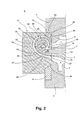
Fig. 2 einen Ausschnitt der Dauergießform gemäßFig. 1 in einem Schnitt entlang der inFig. 1 angedeuteten Schnittlinie X-X. - Die Dauergießform 1 ist auf einer Trägerplatte 2 montiert. Die Trägerplatte 2 ist beispielsweise auf einem nicht dargestellten Transportsystem angeordnet, welches die Dauergießform 1 zu einer hier ebenfalls nicht gezeigten Gießstation transportiert.
- Die Dauergießform 1 ist aus einem üblicherweise aus Formsand hergestellten Formteil 3 sowie aus mehreren Dauergießformteilen zusammengesetzt, von denen hier die Dauergießformteile 4,5,6 sichtbar sind. Dabei bildet das Formteil 3 den Deckel, das Dauergießformteil 4 eine erste Seitenwand, das Dauergießformteil 6 eine zweite Seitenwand und das Dauergießformteil 5 einen Boden der Dauergießform 1. Die Dauergießformteile der Dauergießform 1 können in bekannter Weise aus einem geeigneten Stahl bestehen, der so hochtemperatur- und verschleißbeständig ist, dass die Dauergießformteile für eine große Zahl von Gießvorgängen wiederverwendet werden können.
- Die Dauergießformteile der Dauergießform 1 umgrenzen einen Formhohlraum 7 der Dauergießform 1 gegenüber der Umgebung U und weisen auf ihrer dem Formhohlraum 7 zugeordneten Seite Formelemente 8,9 auf, durch die die äußere Gestalt des zu gießenden Zylinderkopfes abgebildet wird.
- Um die innerhalb des zu gießenden Zylinderkopfes erforderlichen Hohlräume und Kanäle abzubilden, sind in dem Formhohlraum 7 der Dauergießform 1 eine größere Zahl von Formkernen eingelegt, von denen in
Fig. 2 die Formkerne 10,11,12 sichtbar sind. Der Formkern 10 bildet bei der inFig. 2 dargestellten Position der Dauergießform 1 den oberen Bereich des Wassermantelkanals des zu gießenden Zylinderkopfes ab, während der Formkern 11 den unteren Teil dieses Wassermantelkanals abformt. Der mit Abstand zwischen den Formkernen 10,11 angeordnete Formkern 12 bildet dagegen einen in den zu gießenden Zylinderkopf integrierten Abgaskanal ab, durch den entsprechend der in derEP 2 143 926 A1 beschriebenen Entwicklung die Abgasauslässe des zu gießenden Zylinderkopfes gemeinsam zu einer Auslassöffnung geführt sind. - In das die eine Seitenwand der Dauergießform 1 bildende Dauergießformteil 5 ist ausgehend von dem Rand, der dem den Deckel der Dauergießform 1 bildenden Formteil 3 zugeordnet ist, eine Öffnung 13 eingeformt, die sich in Richtung des gegenüberliegenden Rands erstreckt. Die Formkerne 10,11,12 sind jeweils so gestaltet, dass sie an der Öffnung 13 enden bzw. in die Öffnung 13 der Dauergießform 1 vorstehen.
- Die Breite der Öffnung 13 ist gleichzeitig so bemessen, dass sie einen Vorsprung 20 eines Formpakets 21 aufnimmt, das an der Außenseite des Dauergießformteils 6 angeordnet ist. Dieser Vorsprung 20 des Formpakets 21 füllt die Öffnung 13 der Dauergießform 1 vollständig aus und liegt mit seinen seitlich über den Vorsprung 20 hinausgehenden, dem Dauerformteil 6 zugeordneten Wandflächen dicht an der Außenfläche des Dauerformteils 6 an.
- Das beim vorliegenden Ausführungsbeispiel in vertikaler Richtung geteilte Formpaket 21 ist aus mehreren Formteilen 22,23 und Formkernen 24,25 zusammengesetzt, die in an sich bekannter Weise jeweils aus einem an sich ebenfalls bekannten, mit einem geeigneten Binder vermischten Formsand hergestellt sind.
- Das Formteil 22 bildet die eine Hälfte des im zusammengesetzten Zustand blockförmigen Formpakets 21, während die andere Hälfte des Formpakets 21 durch das Formteil 23 gebildet ist. Die Formteile 22,23 umschließen einen Formhohlraumabschnitt 26, in dem die Formkerne 24,25 angeordnet sind und der im Bereich der Stirnseite des in der Öffnung 13 der Dauergießform 1 sitzenden Vorsprungs 20 zum von den Dauergießformteilen 4-6 begrenzten Formhohlraum 7 geöffnet ist.
- Das Formpaket 21 dient zum zeitgleichen einstückigen Angießen eines Gehäuses für einen abgasbetriebenen, mit einer Wasserkühlung versehenen Turbolader an den in der Dauergießform 1 zu gießenden Zylinderkopf. Der eine Formkern 24 des Formpakets 21 bildet einen Wassermantelkanal des zu gießenden Gehäuses ab. Dazu weist der Formkern 24 eine nach Art einer Spirale oder einer Schnecke gekrümmte Form auf. Das bei der Darstellung in
Fig. 2 untere Ende 27 des Formkerns 24 ist dazu so positioniert und geformt, dass dieses Ende bei an dem Dauergießformteil 6 sitzendem Formpaket 21 mit seiner Stirnfläche vollflächig bündig und positionsgenau an der ihm zugeordneten Stirnfläche des Formkerns 11 anliegt, der den unteren Teil des Wassermantels des zu gießenden Zylinderkopfes abbildet. - Ausgehend von diesem Ende 27 läuft der Formkern 24 in einer enger werdenden Spirale nach oben. An seinem bei der Darstellung in
Fig. 2 oberen, das innere Ende der durch den Formkern 24 gebildeten Spirale darstellenden Endabschnitt 28 ist ein in Richtung des Formhohlraums 7 vorstehender Vorsprung 29 ausgebildet. Dessen Stirnfläche ist wiederum so positioniert und geformt, dass sie bei an dem Dauergießformteil 6 sitzendem Formpaket 21 vollflächig bündig und positionsgenau an der ihm zugeordneten Stirnfläche des Formkerns 10 anliegt, der den bei der Darstellung gemäßFig. 2 oberen Teil des Wassermantels des zu gießenden Zylinderkopfes abbildet. - Der zweite Formkern 25 des Formpakets 21 bildet einen im praktischen Einsatz heißes Abgas führenden Abgaskanal ab und sitzt in dem von dem Formkern 24 umgrenzten Raum und weist ebenfalls eine schneckenartige Form auf. Sein bei der Darstellung in
Fig. 2 unterer Endabschnitt 30 ist dabei so positioniert und ausgeformt, dass seine Stirnfläche vollflächig bündig an der ihr zugeordneten Stirnfläche des Formkerns 12 anliegt, der den integrierten Abgaskanal des zu gießenden Zylinderkopfes abbildet. Ausgehend von dem unteren Endabschnitt 30 geht der Formkern 25 der Kontur des Formkerns 24 folgend in einen an seinem anderen Ende ausgebildeten, zapfenförmigen Vorsprung 31 über, dessen Längsachse L sich üblicherweise parallel zur ebenen Außenfläche des Dauergießformteil 6 erstreckt. Der Vorsprung 31 sitzt mit seinem freien Ende formschlüssig in einer entsprechend geformten, hier nicht sichtbaren Ausnehmung des Formteils 22 und bildet an dem zu gießenden Gehäuse eine Auslassöffnung ab, die später das Laufrad des Turboladers aufnehmen kann. - Sowohl zwischen den den Formhohlraumabschnitt 26 begrenzenden Innenflächen 32 der Formteile 22,23 und der ihnen zugewandten äußeren Fläche 34 des Formkerns 24 als auch zwischen der inneren, dem Formkern 25 zugewandten Fläche 35 des Formkerns 24 und der dem Formkern 24 zugewandten Umfangsfläche 36 besteht jeweils durchgehend ein im Wesentlichen konstanter Abstand. Dementsprechend ist in dem Formholraumabschnitt 26 des Formpakets 21 ein erster spiralförmiger äußerer Kanal 37 und getrennt davon ein zweiter ebenfalls spiralförmiger innerer Kanal 38 gebildet. Beide Kanäle 37,38 sind bei an dem Dauergießformteil 6 montiertem Formpaket 21 mit ihrem einen wie mit ihrem anderen Ende jeweils unterbrechungsfrei mit einem freien, nicht durch Formkerne besetzten Bereich des Formhohlraums 7 der Dauergießform 1 verbunden.
- Wird der Formhohlraum 7 der Dauergießform 1 in an sich bekannter Weise über ein hier nicht gezeigtes Gießsystem mit Aluminiumschmelze gefüllt, so strömt die Schmelze bei Erreichen eines bestimmten Füllniveaus unterbrechungsfrei auch in die Kanäle 37,38 des Formpakets 21, bis diese ebenfalls vollständig gefüllt sind.
- Nach dem Erstarren der Schmelze und Entformen des dann fertig gegossenen, hier nicht dargestellten Zylinderkopfes bildet das in dem äußeren Kanal 38 erstarrte Leichtmetall dementsprechend die äußere Wand des einstückig an den Zylinderkopf angegossenen Gehäuses für den Turbolader, während das im Kanal 37 erstarrte Material den durch den Formkern 24 abgebildeten Wassermantel des Turbolader-Gehäuses gegenüber dem durch den Formkern 25 abgebildeten Abgaskanal des Turboladers abgrenzt.
- Die Entformung des an den Zylinderkopf angegossenen Turbolader-Gehäuses erfolgt in an sich bekannter Weise dadurch, dass die Formteile 22,23 und die Formkerne 24,25 durch Einwirkung äußerer Kräfte zerstört werden. Dies kann beispielsweise durch Rütteln des Zylinderkopfes erfolgen, wie es üblicherweise durchgeführt wird, um die im Formhohlraum 7 sitzenden Formkerne 10 - 12 zu zerstören und aus dem fertigen Zylinderkopf ausrieseln zu lassen.
- Um eine passgenaue, lagerichtige Ausrichtung des Formpakets 21 in der Öffnung 13 und an dem Dauergießformteil 6 sowie eine eindeutige lagerichtige Zuordnung der Formkerne 10-12 und 24,25 zu gewährleisten, können an den betreffenden Teilen Formelemente, wie Vorsprünge 39 und korrespondierend geformte Ausnehmungen 40 ausgebildet sein, die bei zusammengesetzter Dauergießform 1 formschlüssig zusammenwirken und so gewährleisten, dass die einander zugeordneten Teile auch unter den beim Gießvorgang oder beim Transport der Dauergießform 1 auftretenden Kräften ihre Position beibehalten.
- Die lagerichtige Ausrichtung des Formpakets 21 an dem Dauergießformteil 6 bzw. in der Öffnung 13 kann darüber hinaus auch dadurch unterstützt werden, dass die die Öffnung 13 umgebenden Randflächenabschnitte zumindest im Bereich des in
Fig. 2 unteren Randabschnitts 14 ausgehend von ihrer dem Formhohlraum 7 zugeordneten Kante in Richtung der Außenfläche des Dauergießformteils 6 so angeschrägt ist, dass sich die Öffnung 13 zumindest in diesem Bereich in Richtung der Umgebung U nach Art eines Trichters erweitert, die Öffnung 13 sich in Richtung des Formhohlraums 7 also konisch zulaufend verengt. Indem der dem derart angeschrägten Abschnitt der Randfläche 14 zugeordnete Flächenabschnitt des Vorsprungs 20 des Formpakets 21 in entsprechender Weise angeschrägt ist, zentriert sich das Formpaket 21 in seiner fertig an dem Dauergießformteil 6 positionierten Stellung zumindest in Richtung der Höhe der Dauergießform 1 selbsttätig. - Auf der Tragplatte 2 ist das Formpaket 21 durch einen Bock 41 abgestützt. Alternativ kann in die Tragplatte 2 in konventioneller Weise eine Kernmarke eingeformt sein, an der das Formpaket 21 hinsichtlich seiner Lage relativ zum zugeordneten Dauergießformteil 6 formschlüssig fixiert ist.
-
- 1
- Dauergießform
- 2
- Trägerplatte
- 3
- Formteil
- 4-6
- Dauergießformteile
- 7
- Formhohlraum
- 8,9
- auf der dem Formhohlraum 7 zugeordneten Seite der Dauergießformteile ausgebildete Formelemente
- 10-12
- Formkerne
- 13
- Öffnung
- 14
- Randfläche der Öffnung 13
- 20
- Vorsprung
- 21
- Formpaket
- 22,23
- Formteile
- 24,25
- Formkerne
- 26
- Formhohlraumabschnitt
- 27
- Ende des Formkerns 24
- 28
- Endabschnitt des Formkerns 24
- 29
- an den Endabschnitt 28 angeformter Vorsprung des Formkerns 24
- 30
- Endabschnitt des Formkerns 25
- 31
- Vorsprung des Formkerns 25
- 32
- Innenflächen der Formteile 22,23
- 34
- äußere Fläche des Formkerns 24
- 35
- innere Fläche des Formkerns 24
- 36
- Umfangsfläche des Formkerns 25
- 37
- Kanal des Formpakets 21
- 38
- Kanal des Formpakets 21
- 39
- Vorsprünge
- 40
- Ausnehmungen
- 41
- Bock
- L
- Längsachse
- U
- Umgebung
Claims (14)
- Dauergießform zum Gießen eines Gussteils aus einer Metallschmelze, wobei die Dauergießform (1) aus mindestens zwei den Formhohlraum (7) der Dauergießform (1) gegenüber der Umgebung (U) abgrenzenden Dauergießformteilen (4-6) zusammengesetzt ist, welche beim Entformen des Gussteils unzerstört erhalten bleiben, dadurch gekennzeichnet, dass an der Dauergießform (1) eine Öffnung (13) ausgebildet ist, an die ein Formpaket (21) angeschlossen ist, das aus einem beim Entformen des Gussteils zerbrechenden Material besteht und einen Formhohlraumabschnitt (26) umgibt, der mit dem Formhohlraum (7) der Dauergießform (1) verbunden ist, so dass in den Formhohlraum (7) der Dauergießform (1) gefüllte Schmelze in die Formhohlraumabschnitte (26) des Formpakets (21) gelangt und umgekehrt.
- Dauergießform nach Anspruch 1, dadurch gekennzeichnet, dass das Formpaket (21) an einer Außenfläche der Dauergießform (1) anliegt.
- Dauergießform nach einem der voranstehenden Ansprüche, dadurch gekennzeichnet, dass an dem Formpaket (21) mindestens ein erstes Formelement (39) und an mindestens einem der Dauergießformteile (4-6) ein korrespondierend zu dem ersten Formelement (39) geformtes zweites Formelement (40) ausgebildet ist, das formschlüssig mit dem Formelement (39) des Formpakets (21) zusammenwirkt.
- Dauergießform nach einem der voranstehenden Ansprüche, dadurch
gekennzeichnet, dass die dem Formpaket (21) zugeordnete Öffnung (13) sich mindestens abschnittsweise ausgehend vom Formhohlraum (7) der Dauergießform (1) in Richtung der Außenfläche der Dauergießform (1) erweitert. - Dauergießform nach Anspruch 4, dadurch gekennzeichnet, dass der Randbereich (14), der die dem Formpaket (21) zugeordnete Öffnung (13) umgibt, mindestens abschnittsweise konisch in Richtung des Formhohlraums (7) der Dauergießform (1) zulaufend oder nach Art einer Kehle ausgebildet ist.
- Dauergießform nach einem der voranstehenden Ansprüche, dadurch gekennzeichnet, dass das Formpaket (21) aus einem sandartigen, mit einem Binder vermischten Formstoff geformt ist.
- Dauergießform nach einem der voranstehenden Ansprüche, dadurch gekennzeichnet, dass das Formpaket (21) aus zwei oder mehr Formteilen (22,23) oder Formkernen (24,25) zusammengesetzt ist.
- Dauergießform nach einem der voranstehenden Ansprüche, dadurch
gekennzeichnet, dass sie zum Gießen eines Zylinderkopfs für einen Verbrennungsmotor bestimmt ist und dass das Formpaket (21) ein Funktionsteil abbildet, das bei fertig gegossenem Zylinderkopf einstückig mit dem Zylinderkopf verbunden ist und mindestens einen Kanal aufweist, der unterbrechungsfrei mit einem Kanal des Zylinderkopfs verbunden ist. - Dauergießform nach Anspruch 8, dadurch gekennzeichnet, dass das Formpaket (21) einen ersten Formkern (24), der einen mit dem Wassermantel des zu gießenden Zylinderkopfs verbundenen Wasserkanal des Funktionsteils abbildet, und einen zweiten Formkern (25) umfasst, der einen mit einem Abgas führenden Kanal des Zylinderkopfs verbundenen Abgaskanal des Funktionsteils abbildet.
- Dauergießform nach einem der Ansprüche 8 oder 9, dadurch gekennzeichnet, dass das Funktionsteil ein Gehäuseteil für einen Turbolader ist.
- Dauergießform nach einem der voranstehenden Ansprüche, dadurch
gekennzeichnet, dass das Formpaket (21) an einem die Dauergießform (1) haltenden Bock (41) abgestützt ist. - Dauergießform nach einem der voranstehenden Ansprüche, dadurch
gekennzeichnet, dass das Formpaket (21) an einer Kernmarke in der Trägerplatte (2) positioniert ist. - Dauergießform nach einem der voranstehenden Ansprüche, dadurch gekennzeichnet, dass an ihr mindestens ein Formelement zum Abbilden eines Erstaufnahmepunkts an dem Gussteil vorgesehen ist.
- Dauergießform nach Anspruch 13, dadurch gekennzeichnet, dass an ihr ein zusätzliches Formelement vorgesehen ist, welches an dem in dem Formpaket (21) abgebildeten Abschnitt des Gussteils einen zusätzlichen Erstaufnahmepunkt abbildet.
Applications Claiming Priority (1)
| Application Number | Priority Date | Filing Date | Title |
|---|---|---|---|
| DE201010025285 DE102010025285A1 (de) | 2010-06-28 | 2010-06-28 | Dauergießform zum Gießen von Gussstücken aus einer Metallschmelze |
Publications (2)
| Publication Number | Publication Date |
|---|---|
| EP2399692A1 true EP2399692A1 (de) | 2011-12-28 |
| EP2399692B1 EP2399692B1 (de) | 2015-02-18 |
Family
ID=44721165
Family Applications (1)
| Application Number | Title | Priority Date | Filing Date |
|---|---|---|---|
| EP20110171279 Active EP2399692B1 (de) | 2010-06-28 | 2011-06-24 | Gießform zum Gießen von Gussstücken aus einer Metallschmelze |
Country Status (2)
| Country | Link |
|---|---|
| EP (1) | EP2399692B1 (de) |
| DE (1) | DE102010025285A1 (de) |
Cited By (4)
| Publication number | Priority date | Publication date | Assignee | Title |
|---|---|---|---|---|
| CN104741547A (zh) * | 2015-04-01 | 2015-07-01 | 无锡蠡湖增压技术股份有限公司 | 一种带热碰模的压气壳用无砂芯金属模具 |
| CN106180577A (zh) * | 2016-09-28 | 2016-12-07 | 江苏华培动力科技有限公司 | 双涡流涡壳砂芯无缝组合工艺 |
| CN106424582A (zh) * | 2016-10-28 | 2017-02-22 | 江苏华培动力科技有限公司 | 涡轮增压器壳体铸造用砂芯成型工艺 |
| CN112566739A (zh) * | 2018-11-09 | 2021-03-26 | 宝马股份公司 | 用于制造曲轴箱的锭模和方法 |
Families Citing this family (1)
| Publication number | Priority date | Publication date | Assignee | Title |
|---|---|---|---|---|
| DE102017211876B3 (de) | 2017-07-12 | 2018-08-16 | Bayerische Motoren Werke Aktiengesellschaft | Kokille sowie Verfahren zum Herstellen eines Bauteils |
Citations (3)
| Publication number | Priority date | Publication date | Assignee | Title |
|---|---|---|---|---|
| EP0872295A1 (de) * | 1997-04-15 | 1998-10-21 | Wärtsilä NSD Schweiz AG | Giessform und Verfahren zum Herstellen von metallischen Hohlgiesslingen sowie Hohlgiesslinge |
| EP1536141A1 (de) * | 2003-11-28 | 2005-06-01 | BorgWarner Inc. | Gehäuse für Turbolader |
| EP2143926A1 (de) | 2008-07-11 | 2010-01-13 | Ford Global Technologies, LLC | Kombination mit Zylinderkopf und Turbine |
Family Cites Families (4)
| Publication number | Priority date | Publication date | Assignee | Title |
|---|---|---|---|---|
| DE202004020207U1 (de) * | 2004-12-27 | 2005-04-07 | Univ Magdeburg Tech | Einrichtung zum Schwerkraftgießen von Leichtmetallgussteilen im Kokillen-Gießverfahren |
| US7438117B2 (en) * | 2006-01-19 | 2008-10-21 | Gm Global Technology Operations, Inc. | Cylinder block casting bulkhead window formation |
| DE102007004050B4 (de) * | 2007-01-22 | 2010-03-18 | Ks Aluminium-Technologie Gmbh | Vorrichtung zum Herstellen eines Zylinderkurbelgehäuses |
| DE102007030482B4 (de) * | 2007-06-30 | 2018-12-20 | Dr. Ing. H.C. F. Porsche Aktiengesellschaft | Kühlkanäle im Zylinderkopf einer Brennkraftmaschine |
-
2010
- 2010-06-28 DE DE201010025285 patent/DE102010025285A1/de not_active Withdrawn
-
2011
- 2011-06-24 EP EP20110171279 patent/EP2399692B1/de active Active
Patent Citations (4)
| Publication number | Priority date | Publication date | Assignee | Title |
|---|---|---|---|---|
| EP0872295A1 (de) * | 1997-04-15 | 1998-10-21 | Wärtsilä NSD Schweiz AG | Giessform und Verfahren zum Herstellen von metallischen Hohlgiesslingen sowie Hohlgiesslinge |
| EP1536141A1 (de) * | 2003-11-28 | 2005-06-01 | BorgWarner Inc. | Gehäuse für Turbolader |
| EP2143926A1 (de) | 2008-07-11 | 2010-01-13 | Ford Global Technologies, LLC | Kombination mit Zylinderkopf und Turbine |
| EP2143922A1 (de) | 2008-07-11 | 2010-01-13 | Ford Global Technologies, LLC | Zylinderkopf mit Abgaskrümmer und Turbolader |
Cited By (5)
| Publication number | Priority date | Publication date | Assignee | Title |
|---|---|---|---|---|
| CN104741547A (zh) * | 2015-04-01 | 2015-07-01 | 无锡蠡湖增压技术股份有限公司 | 一种带热碰模的压气壳用无砂芯金属模具 |
| CN106180577A (zh) * | 2016-09-28 | 2016-12-07 | 江苏华培动力科技有限公司 | 双涡流涡壳砂芯无缝组合工艺 |
| CN106180577B (zh) * | 2016-09-28 | 2018-11-27 | 江苏华培动力科技有限公司 | 双涡流涡壳砂芯无缝组合工艺 |
| CN106424582A (zh) * | 2016-10-28 | 2017-02-22 | 江苏华培动力科技有限公司 | 涡轮增压器壳体铸造用砂芯成型工艺 |
| CN112566739A (zh) * | 2018-11-09 | 2021-03-26 | 宝马股份公司 | 用于制造曲轴箱的锭模和方法 |
Also Published As
| Publication number | Publication date |
|---|---|
| DE102010025285A1 (de) | 2011-12-29 |
| EP2399692B1 (de) | 2015-02-18 |
Similar Documents
| Publication | Publication Date | Title |
|---|---|---|
| DE102014101080B3 (de) | Vorrichtung zur Herstellung eines Zylinderkurbelgehäuses im Niederdruck- oder Schwerkraftgießverfahren | |
| EP2091678B1 (de) | Giessform zum giessen eines gussteils und verwendung einer solchen giessform | |
| EP2945760B1 (de) | Giessform zur herstellung von gussteilen, insbesondere zylinderblöcken und zylinderköpfen, mit funktionaler anbindung des speisers | |
| EP2399692B1 (de) | Gießform zum Gießen von Gussstücken aus einer Metallschmelze | |
| EP3570992B1 (de) | Giessform zum giessen von komplex geformten gussteilen und verwendung einer solchen giessform | |
| EP0872295B1 (de) | Giessform und Verfahren zum Herstellen von metallischen Hohlgiesslingen sowie Hohlgiesslinge | |
| DE112014004716T5 (de) | Verfahren und Gießmaschine zum Gießen von Metallteilen | |
| EP1948374B1 (de) | Dauergiessform und giessformeinsatz | |
| DE69908212T2 (de) | Verfahren und Einrichtung zum Giessen von Teilen aus Leichtmetall-Legierungen | |
| DE10153721B4 (de) | Gießwerkzeug zur Herstellung eines Zylinderkurbelgehäuses | |
| DE102013021197B3 (de) | Verfahren zum Herstellen eines Gießkerns sowie Gießkern | |
| EP1981667B1 (de) | VERFAHREN ZUM MONTIEREN EINER GIEßFORM ZUM GIEßEN EINES GUSSTEILS AUS EINER METALLSCHMELZE | |
| EP1002602A1 (de) | Vorrichtung und Verfahren für die Herstellung eines Motorblocks | |
| DE102006001946B4 (de) | Zylinderbuchseneinlegeteil für ein Zylindergehäuse einer Hubkolben-Brennkraftmaschine und Verfahren zur Herstellung eines solchen Zylinderbuchseneinlegeteis | |
| DE102010025286B4 (de) | Leichtmetallgussteil für einen Verbrennungsmotor | |
| DE102007015051A1 (de) | Kern für Druckgiessformen | |
| EP1872885A2 (de) | Zylinderkurbelgehäuse und Verfahren zur Herstellung | |
| EP1204516B1 (de) | Verfahren zur herstellung eines hohlkörpers in schmelzkerntechnik | |
| DE102005030814B4 (de) | Gussform für den Metallguss | |
| DE112011102887B4 (de) | Form, Verwendung und Entwurfsverfahren der Form | |
| EP3427859A1 (de) | Giesskern für eine sanitärarmatur, verwendung des giesskerns zur herstellung einer sanitärarmatur, verfahren zur herstellung der sanitärarmatur und sanitärarmatur | |
| DE102017126178A1 (de) | Gießkern für eine Sanitärarmatur und Sanitärarmatur | |
| DE202010018001U1 (de) | Leichtmetallgussteil für einen Verbrennungsmotor | |
| DE102014204859A1 (de) | Zylinderkopfbauteil und Verfahren zur Herstellung eines solchen | |
| DE60003507T2 (de) | Verfahren zur Beschickung mit Giessmaterial bei Gussstücken mit Einsatz |
Legal Events
| Date | Code | Title | Description |
|---|---|---|---|
| AK | Designated contracting states |
Kind code of ref document: A1 Designated state(s): AL AT BE BG CH CY CZ DE DK EE ES FI FR GB GR HR HU IE IS IT LI LT LU LV MC MK MT NL NO PL PT RO RS SE SI SK SM TR |
|
| AX | Request for extension of the european patent |
Extension state: BA ME |
|
| PUAI | Public reference made under article 153(3) epc to a published international application that has entered the european phase |
Free format text: ORIGINAL CODE: 0009012 |
|
| 17P | Request for examination filed |
Effective date: 20120625 |
|
| GRAP | Despatch of communication of intention to grant a patent |
Free format text: ORIGINAL CODE: EPIDOSNIGR1 |
|
| INTG | Intention to grant announced |
Effective date: 20140724 |
|
| GRAP | Despatch of communication of intention to grant a patent |
Free format text: ORIGINAL CODE: EPIDOSNIGR1 |
|
| INTG | Intention to grant announced |
Effective date: 20140825 |
|
| GRAS | Grant fee paid |
Free format text: ORIGINAL CODE: EPIDOSNIGR3 |
|
| GRAA | (expected) grant |
Free format text: ORIGINAL CODE: 0009210 |
|
| AK | Designated contracting states |
Kind code of ref document: B1 Designated state(s): AL AT BE BG CH CY CZ DE DK EE ES FI FR GB GR HR HU IE IS IT LI LT LU LV MC MK MT NL NO PL PT RO RS SE SI SK SM TR |
|
| REG | Reference to a national code |
Ref country code: GB Ref legal event code: FG4D Free format text: NOT ENGLISH |
|
| REG | Reference to a national code |
Ref country code: CH Ref legal event code: EP |
|
| REG | Reference to a national code |
Ref country code: AT Ref legal event code: REF Ref document number: 710439 Country of ref document: AT Kind code of ref document: T Effective date: 20150315 |
|
| REG | Reference to a national code |
Ref country code: IE Ref legal event code: FG4D Free format text: LANGUAGE OF EP DOCUMENT: GERMAN |
|
| REG | Reference to a national code |
Ref country code: DE Ref legal event code: R096 Ref document number: 502011005884 Country of ref document: DE Effective date: 20150402 |
|
| REG | Reference to a national code |
Ref country code: NL Ref legal event code: VDEP Effective date: 20150218 |
|
| REG | Reference to a national code |
Ref country code: LT Ref legal event code: MG4D |
|
| PG25 | Lapsed in a contracting state [announced via postgrant information from national office to epo] |
Ref country code: FI Free format text: LAPSE BECAUSE OF FAILURE TO SUBMIT A TRANSLATION OF THE DESCRIPTION OR TO PAY THE FEE WITHIN THE PRESCRIBED TIME-LIMIT Effective date: 20150218 Ref country code: HR Free format text: LAPSE BECAUSE OF FAILURE TO SUBMIT A TRANSLATION OF THE DESCRIPTION OR TO PAY THE FEE WITHIN THE PRESCRIBED TIME-LIMIT Effective date: 20150218 Ref country code: NO Free format text: LAPSE BECAUSE OF FAILURE TO SUBMIT A TRANSLATION OF THE DESCRIPTION OR TO PAY THE FEE WITHIN THE PRESCRIBED TIME-LIMIT Effective date: 20150518 Ref country code: SE Free format text: LAPSE BECAUSE OF FAILURE TO SUBMIT A TRANSLATION OF THE DESCRIPTION OR TO PAY THE FEE WITHIN THE PRESCRIBED TIME-LIMIT Effective date: 20150218 Ref country code: LT Free format text: LAPSE BECAUSE OF FAILURE TO SUBMIT A TRANSLATION OF THE DESCRIPTION OR TO PAY THE FEE WITHIN THE PRESCRIBED TIME-LIMIT Effective date: 20150218 Ref country code: ES Free format text: LAPSE BECAUSE OF FAILURE TO SUBMIT A TRANSLATION OF THE DESCRIPTION OR TO PAY THE FEE WITHIN THE PRESCRIBED TIME-LIMIT Effective date: 20150218 |
|
| PG25 | Lapsed in a contracting state [announced via postgrant information from national office to epo] |
Ref country code: RS Free format text: LAPSE BECAUSE OF FAILURE TO SUBMIT A TRANSLATION OF THE DESCRIPTION OR TO PAY THE FEE WITHIN THE PRESCRIBED TIME-LIMIT Effective date: 20150218 Ref country code: NL Free format text: LAPSE BECAUSE OF FAILURE TO SUBMIT A TRANSLATION OF THE DESCRIPTION OR TO PAY THE FEE WITHIN THE PRESCRIBED TIME-LIMIT Effective date: 20150218 Ref country code: LV Free format text: LAPSE BECAUSE OF FAILURE TO SUBMIT A TRANSLATION OF THE DESCRIPTION OR TO PAY THE FEE WITHIN THE PRESCRIBED TIME-LIMIT Effective date: 20150218 Ref country code: GR Free format text: LAPSE BECAUSE OF FAILURE TO SUBMIT A TRANSLATION OF THE DESCRIPTION OR TO PAY THE FEE WITHIN THE PRESCRIBED TIME-LIMIT Effective date: 20150519 Ref country code: IS Free format text: LAPSE BECAUSE OF FAILURE TO SUBMIT A TRANSLATION OF THE DESCRIPTION OR TO PAY THE FEE WITHIN THE PRESCRIBED TIME-LIMIT Effective date: 20150618 |
|
| PG25 | Lapsed in a contracting state [announced via postgrant information from national office to epo] |
Ref country code: CZ Free format text: LAPSE BECAUSE OF FAILURE TO SUBMIT A TRANSLATION OF THE DESCRIPTION OR TO PAY THE FEE WITHIN THE PRESCRIBED TIME-LIMIT Effective date: 20150218 Ref country code: RO Free format text: LAPSE BECAUSE OF FAILURE TO SUBMIT A TRANSLATION OF THE DESCRIPTION OR TO PAY THE FEE WITHIN THE PRESCRIBED TIME-LIMIT Effective date: 20150218 Ref country code: SK Free format text: LAPSE BECAUSE OF FAILURE TO SUBMIT A TRANSLATION OF THE DESCRIPTION OR TO PAY THE FEE WITHIN THE PRESCRIBED TIME-LIMIT Effective date: 20150218 Ref country code: DK Free format text: LAPSE BECAUSE OF FAILURE TO SUBMIT A TRANSLATION OF THE DESCRIPTION OR TO PAY THE FEE WITHIN THE PRESCRIBED TIME-LIMIT Effective date: 20150218 Ref country code: EE Free format text: LAPSE BECAUSE OF FAILURE TO SUBMIT A TRANSLATION OF THE DESCRIPTION OR TO PAY THE FEE WITHIN THE PRESCRIBED TIME-LIMIT Effective date: 20150218 |
|
| REG | Reference to a national code |
Ref country code: DE Ref legal event code: R097 Ref document number: 502011005884 Country of ref document: DE |
|
| PG25 | Lapsed in a contracting state [announced via postgrant information from national office to epo] |
Ref country code: PL Free format text: LAPSE BECAUSE OF FAILURE TO SUBMIT A TRANSLATION OF THE DESCRIPTION OR TO PAY THE FEE WITHIN THE PRESCRIBED TIME-LIMIT Effective date: 20150218 |
|
| PLBE | No opposition filed within time limit |
Free format text: ORIGINAL CODE: 0009261 |
|
| STAA | Information on the status of an ep patent application or granted ep patent |
Free format text: STATUS: NO OPPOSITION FILED WITHIN TIME LIMIT |
|
| 26N | No opposition filed |
Effective date: 20151119 |
|
| PG25 | Lapsed in a contracting state [announced via postgrant information from national office to epo] |
Ref country code: MC Free format text: LAPSE BECAUSE OF FAILURE TO SUBMIT A TRANSLATION OF THE DESCRIPTION OR TO PAY THE FEE WITHIN THE PRESCRIBED TIME-LIMIT Effective date: 20150218 |
|
| REG | Reference to a national code |
Ref country code: CH Ref legal event code: PL |
|
| PG25 | Lapsed in a contracting state [announced via postgrant information from national office to epo] |
Ref country code: SI Free format text: LAPSE BECAUSE OF FAILURE TO SUBMIT A TRANSLATION OF THE DESCRIPTION OR TO PAY THE FEE WITHIN THE PRESCRIBED TIME-LIMIT Effective date: 20150218 Ref country code: LU Free format text: LAPSE BECAUSE OF FAILURE TO SUBMIT A TRANSLATION OF THE DESCRIPTION OR TO PAY THE FEE WITHIN THE PRESCRIBED TIME-LIMIT Effective date: 20150624 |
|
| REG | Reference to a national code |
Ref country code: IE Ref legal event code: MM4A |
|
| PG25 | Lapsed in a contracting state [announced via postgrant information from national office to epo] |
Ref country code: CH Free format text: LAPSE BECAUSE OF NON-PAYMENT OF DUE FEES Effective date: 20150630 Ref country code: IE Free format text: LAPSE BECAUSE OF NON-PAYMENT OF DUE FEES Effective date: 20150624 Ref country code: LI Free format text: LAPSE BECAUSE OF NON-PAYMENT OF DUE FEES Effective date: 20150630 |
|
| REG | Reference to a national code |
Ref country code: FR Ref legal event code: PLFP Year of fee payment: 6 |
|
| PG25 | Lapsed in a contracting state [announced via postgrant information from national office to epo] |
Ref country code: MT Free format text: LAPSE BECAUSE OF FAILURE TO SUBMIT A TRANSLATION OF THE DESCRIPTION OR TO PAY THE FEE WITHIN THE PRESCRIBED TIME-LIMIT Effective date: 20150218 |
|
| PG25 | Lapsed in a contracting state [announced via postgrant information from national office to epo] |
Ref country code: BG Free format text: LAPSE BECAUSE OF FAILURE TO SUBMIT A TRANSLATION OF THE DESCRIPTION OR TO PAY THE FEE WITHIN THE PRESCRIBED TIME-LIMIT Effective date: 20150218 Ref country code: HU Free format text: LAPSE BECAUSE OF FAILURE TO SUBMIT A TRANSLATION OF THE DESCRIPTION OR TO PAY THE FEE WITHIN THE PRESCRIBED TIME-LIMIT; INVALID AB INITIO Effective date: 20110624 Ref country code: SM Free format text: LAPSE BECAUSE OF FAILURE TO SUBMIT A TRANSLATION OF THE DESCRIPTION OR TO PAY THE FEE WITHIN THE PRESCRIBED TIME-LIMIT Effective date: 20150218 |
|
| REG | Reference to a national code |
Ref country code: FR Ref legal event code: PLFP Year of fee payment: 7 |
|
| PG25 | Lapsed in a contracting state [announced via postgrant information from national office to epo] |
Ref country code: CY Free format text: LAPSE BECAUSE OF FAILURE TO SUBMIT A TRANSLATION OF THE DESCRIPTION OR TO PAY THE FEE WITHIN THE PRESCRIBED TIME-LIMIT Effective date: 20150218 |
|
| PG25 | Lapsed in a contracting state [announced via postgrant information from national office to epo] |
Ref country code: BE Free format text: LAPSE BECAUSE OF NON-PAYMENT OF DUE FEES Effective date: 20150630 |
|
| REG | Reference to a national code |
Ref country code: AT Ref legal event code: MM01 Ref document number: 710439 Country of ref document: AT Kind code of ref document: T Effective date: 20160624 |
|
| PG25 | Lapsed in a contracting state [announced via postgrant information from national office to epo] |
Ref country code: TR Free format text: LAPSE BECAUSE OF FAILURE TO SUBMIT A TRANSLATION OF THE DESCRIPTION OR TO PAY THE FEE WITHIN THE PRESCRIBED TIME-LIMIT Effective date: 20150218 |
|
| PG25 | Lapsed in a contracting state [announced via postgrant information from national office to epo] |
Ref country code: AT Free format text: LAPSE BECAUSE OF NON-PAYMENT OF DUE FEES Effective date: 20160624 |
|
| REG | Reference to a national code |
Ref country code: FR Ref legal event code: PLFP Year of fee payment: 8 |
|
| PG25 | Lapsed in a contracting state [announced via postgrant information from national office to epo] |
Ref country code: MK Free format text: LAPSE BECAUSE OF FAILURE TO SUBMIT A TRANSLATION OF THE DESCRIPTION OR TO PAY THE FEE WITHIN THE PRESCRIBED TIME-LIMIT Effective date: 20150218 Ref country code: PT Free format text: LAPSE BECAUSE OF FAILURE TO SUBMIT A TRANSLATION OF THE DESCRIPTION OR TO PAY THE FEE WITHIN THE PRESCRIBED TIME-LIMIT Effective date: 20150218 |
|
| PG25 | Lapsed in a contracting state [announced via postgrant information from national office to epo] |
Ref country code: AL Free format text: LAPSE BECAUSE OF FAILURE TO SUBMIT A TRANSLATION OF THE DESCRIPTION OR TO PAY THE FEE WITHIN THE PRESCRIBED TIME-LIMIT Effective date: 20150218 |
|
| PGFP | Annual fee paid to national office [announced via postgrant information from national office to epo] |
Ref country code: DE Payment date: 20230921 Year of fee payment: 13 |
|
| PGFP | Annual fee paid to national office [announced via postgrant information from national office to epo] |
Ref country code: GB Payment date: 20231227 Year of fee payment: 13 |
|
| PGFP | Annual fee paid to national office [announced via postgrant information from national office to epo] |
Ref country code: IT Payment date: 20231227 Year of fee payment: 13 Ref country code: FR Payment date: 20231227 Year of fee payment: 13 |