EP2398678B1 - Damper assembly and device utilizing the same - Google Patents
Damper assembly and device utilizing the same Download PDFInfo
- Publication number
- EP2398678B1 EP2398678B1 EP10744100.8A EP10744100A EP2398678B1 EP 2398678 B1 EP2398678 B1 EP 2398678B1 EP 10744100 A EP10744100 A EP 10744100A EP 2398678 B1 EP2398678 B1 EP 2398678B1
- Authority
- EP
- European Patent Office
- Prior art keywords
- damper
- gear
- housing
- bracket
- assembly
- Prior art date
- Legal status (The legal status is an assumption and is not a legal conclusion. Google has not performed a legal analysis and makes no representation as to the accuracy of the status listed.)
- Not-in-force
Links
- 238000013016 damping Methods 0.000 description 17
- 230000000712 assembly Effects 0.000 description 4
- 238000000429 assembly Methods 0.000 description 4
- 230000000694 effects Effects 0.000 description 4
- 239000012530 fluid Substances 0.000 description 4
- 230000001133 acceleration Effects 0.000 description 3
- 238000009434 installation Methods 0.000 description 2
- 239000000463 material Substances 0.000 description 2
- 239000004677 Nylon Substances 0.000 description 1
- 239000000853 adhesive Substances 0.000 description 1
- 230000001070 adhesive effect Effects 0.000 description 1
- 230000015572 biosynthetic process Effects 0.000 description 1
- 230000005465 channeling Effects 0.000 description 1
- 230000001010 compromised effect Effects 0.000 description 1
- 238000010276 construction Methods 0.000 description 1
- 238000005755 formation reaction Methods 0.000 description 1
- 230000013011 mating Effects 0.000 description 1
- 238000000034 method Methods 0.000 description 1
- 238000012986 modification Methods 0.000 description 1
- 230000004048 modification Effects 0.000 description 1
- 229920001778 nylon Polymers 0.000 description 1
- 239000004033 plastic Substances 0.000 description 1
- 230000000452 restraining effect Effects 0.000 description 1
- 238000003466 welding Methods 0.000 description 1
Images


Classifications
-
- F—MECHANICAL ENGINEERING; LIGHTING; HEATING; WEAPONS; BLASTING
- F16—ENGINEERING ELEMENTS AND UNITS; GENERAL MEASURES FOR PRODUCING AND MAINTAINING EFFECTIVE FUNCTIONING OF MACHINES OR INSTALLATIONS; THERMAL INSULATION IN GENERAL
- F16F—SPRINGS; SHOCK-ABSORBERS; MEANS FOR DAMPING VIBRATION
- F16F9/00—Springs, vibration-dampers, shock-absorbers, or similarly-constructed movement-dampers using a fluid or the equivalent as damping medium
- F16F9/10—Springs, vibration-dampers, shock-absorbers, or similarly-constructed movement-dampers using a fluid or the equivalent as damping medium using liquid only; using a fluid of which the nature is immaterial
- F16F9/12—Devices with one or more rotary vanes turning in the fluid any throttling effect being immaterial, i.e. damping by viscous shear effect only
-
- Y—GENERAL TAGGING OF NEW TECHNOLOGICAL DEVELOPMENTS; GENERAL TAGGING OF CROSS-SECTIONAL TECHNOLOGIES SPANNING OVER SEVERAL SECTIONS OF THE IPC; TECHNICAL SUBJECTS COVERED BY FORMER USPC CROSS-REFERENCE ART COLLECTIONS [XRACs] AND DIGESTS
- Y10—TECHNICAL SUBJECTS COVERED BY FORMER USPC
- Y10T—TECHNICAL SUBJECTS COVERED BY FORMER US CLASSIFICATION
- Y10T74/00—Machine element or mechanism
- Y10T74/19—Gearing
- Y10T74/19637—Gearing with brake means for gearing
Definitions
- the present invention relates generally to damper assemblies, drive arrangements for damper assemblies and structures and devices utilizing damper assemblies. More specifically, the invention pertains to a drive arrangement for a one-way movement damper assembly and a retractable strap type crowd control device using the damper assembly.
- Movement dampers are used in a wide variety of devices to control the movement of device components. In some situations, dampers are used to control movements of components that would otherwise move more suddenly and forcefully than desired. The damper may control movement caused by gravitational forces or movement induced by springs or other actuators. Doors, drawers and pullouts in furniture are some examples of known applications for dampers. In automobiles, dampers are known for use on, for example, glove box doors, console covers, sunglass bins, retractable cup holders and other storage bins or storage areas. Many other devices also use dampers.
- Viscous dampers are known.
- a rotor is rotatable within a housing that contains a viscous damping fluid.
- Internal structures of the rotor and/or housing establish ports for relative movement of the damping fluid and rotor, thereby providing a desired degree of resistance or "damping".
- Both one-way and two-way dampers are known. As the names imply, a one-way damper controls movement in only one direction while applying minimal resistance to movement in the opposite direction, and a two-way damper provides resistance or control of movement in both directions.
- a one-way damper controls movement in only one direction while applying minimal resistance to movement in the opposite direction
- a two-way damper provides resistance or control of movement in both directions.
- driving structure between the damper and the component controlled that engages for movement in one direction and disengages for movement in the other direction. The engagement and disengagement can be problematic if not effected completely, and operation is compromised if not firmly engaged and/or noisy if not completely disengaged and separated.
- the present invention provides a damper with a drive arrangement that engages and disengages effectively, which can be used within a reel assembly of a crowd control device so that a strap can be unwound from the reel without interference, but unguided rewind is controlled at even, consistent acceleration so that random whipping is minimized. Biasing force is applied in opposite directions from between the damper and the damper gear against the damper and damper gear.
- a movement dampened device is provided with a moving component of the device during operation, a nonmoving component of the device during operation and a device gear connected to one of the moving and nonmoving components.
- a damper assembly is connected to the other of the moving and nonmoving components.
- the damper assembly includes a damper having a rotor and a rotor shaft, a damper gear operatively disposed on the rotor shaft for operative engagement with the device gear and a biasing means between the damper and the damper gear exerting force against the damper and the damper gear in opposite directions.
- a damper assembly is provided with a damper including a housing, a rotor in the housing and a rotor shaft extending outwardly from the housing, and a damper gear disposed on a distal end of the rotor shaft.
- a damper bracket has a body between the damper and the damper gear and legs disposed outwardly of the damper and defining features therein for attaching the damper assembly in a device.
- Cooperating engaging structures on the damper housing and the damper bracket are provided for selectively engaging and disengaging the damper housing from the bracket for enabling and disabling relative rotation therebetween.
- the damper bracket defines biasing structure operating against the damper housing and against a side of the damper gear facing the damper housing.
- a damper assembly is provided with a damper bracket having a body and legs and a damper disposed between the damper legs on one side of the damper bracket body.
- a rotor in the damper has a shaft extending outwardly therefrom through the damper bracket body.
- a damper gear is disposed on the rotor shaft on a second side of the damper bracket body.
- the damper bracket body is configured to provide biasing force from between the damper and the damper gear, the biasing force being exerted against each the damper and the damper gear.
- An advantage of one aspect of an embodiment of the damper drive arrangement disclosed herein is that it provides effective engagement and disengagement of the damper drive mechanism.
- damper drive arrangement can be installed in retractable belt-type crowd control devices to minimize random whipping during rewind.
- Damper assembly 100 includes a damper 102 and a drive assembly 104 including a bracket 106 and a damper gear 108.
- Damper 102 is a viscous rotary gear damper having an outer housing 110, which may be multiple components fastened one to another by, for example, ultrasonic welding.
- housing 110 includes a shell 112 and a cover 114 attached thereto.
- Shell 112 and cover 114 together define an interior volume 116 which is filled with a viscous damping fluid in the completed assembly.
- Shell 112 defines cogs or ribs 118 on the outer periphery thereof, which, in the exemplary embodiment, surround shell 110 at one end of damper 102.
- Cogs 118 are fixed elements with respect to shell 112, and can be integral formations in shell 112.
- Damper 102 further includes a rotor 120 which is rotatable within volume 116 and includes a shaft 122 which extends outwardly of cover 114 through a hole 124.
- a flattened distal end 126 of shaft 122 is configured for driving engagement with damper gear 108 so that rotation of shaft 122 causes damper gear 108 to rotate directly with shaft 122.
- viscous dampers include baffles and restrictions of various types for channeling the movement of damping fluid relative to rotation of a rotor within a contained space to control the rotation of the rotor and provide a damping function. Accordingly, rotation of the external gear connected to the rotor is controlled, and the controlled rotation can be transferred through a gear couple between the exposed gear connected to the rotor and a gear on the device the movement of which is to be controlled, such as a windup spool for a crowd control device.
- Bracket 106 includes a main body 130 and mounting legs 132, 134 projecting from diametrically opposed sides of body 130.
- each mounting leg 132, 134 defines a hole 136, 138, respectively, for receiving fasteners 140, 142 ( Fig. 7 ) for attaching bracket 106 in an installation.
- fasteners 140, 142 are threaded screw-type fasteners. It should be understood that other types of attachment are also possible, such as, for example and not limitation, fasteners of types other than screws; attachments without independent fasteners, such as snap-in features on the legs received in holes; and clamps, hold-downs or adhesives for securing the bracket within an installation.
- One leg 134 defines cogs or teeth 144 on the inside thereof to engage cogs or ribs 118 on shell 110.
- Body 130 defines a central aperture 146 through which damper shaft 122 extends.
- Central aperture 146 is formed with and in body 130 so as to establish an upwardly extending ridge or rim 148 along the edge of material defining aperture 146.
- One or more flex bar 150, 152 is defined in body 130 outwardly and on opposite sides of central aperture 146. In the exemplary embodiment two such flex bars 150, 152 are shown, one flex bar 150, 152 on each of opposite sides of central aperture 146.
- Flex bars 150, 152 in the exemplary embodiment shown are arcuate bodies defined between pairs of curved slots 154, 156 and 158, 160 respectively.
- Bracket 106 is configured, installed and adapted to provide biasing forces in opposite directions from between housing 110 and damper gear 108. Accordingly, legs 132, 134 are sized so that bracket 106 provides downward clamping force against housing 110 when damper assembly 100 is installed. Arcuate flex bars 150, 152 are positioned to bias against the upper surface of cover 114 as a radially outermost portion 162 ( Fig. 3 ) of body 130 is drawn downwardly when legs 132, 134 are fastened in place. At the same time, a radially inner most portion 164 of body 130 is clamped between cover 114 and the underside of the damper gear 108. Bracket 106 also may include one or more protrusion 166 or other feature for locating bracket 106 within a device.
- Damper gear 108 is connected by a snap-fit connection onto rotor shaft 122.
- the snap-fit connection is configured such that prior to snapping together, the gear is caused to push down against rim 148 while innermost portion 164 is pushed against cover 114 of damper housing 110. Then, when the gear is snapped to the post of the rotor, there is a built in biasing force between the top of the damper and the gear on the post.
- the bracket including flex bars 150, 152 and outer and inner portions 162, 164 ensures a tight or desirable connection between the gear and the damper on account of the force applied by the flex bars against the damper and the gear.
- bracket 106 helps ensure the mating of the cogs during damping and disengagement of the cogs during free running.
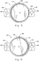
- Damper assembly 100 uses the engagement and disengagement of cooperating engagement structures on housing 110 and bracket 106, that is cogs 118 and cogs 144, to alternatively provide damping effect (when the cogs are engaged) and free-wheeling with no damping effect (when the cogs are disengaged.
- damper housing 110 can move relative to bracket 106. Accordingly, no relative rotation occurs between damper housing 110 and rotor 120.
- damper housing 110 is held stationary relative to bracket 106. Accordingly, relative rotation occurs between damper housing 110 and rotor 120 such that damping effect is transferred via damper gear 108.
- Flex bars 150, 152 help hold damper 102 and bracket 106 in place, either in the damping condition when the cogs engage ( Fig. 5 ) or in the free run condition when the cogs do not engage ( Fig. 6 ). Without the resistance or desired force applied by bracket 106 against damper 102 and damper gear 108, the cogs may not engage or disengage as desired, particularly if the vertical orientation of the damper is altered, such as when a crowd control device on a post is tipped over. When the free running, non-damping condition is desired, the flex bars cooperate with the damper and gear to ensure non-engagement between the cogs.
- the cogs may undesirably engage partially, causing an unwanted ratcheting noise from operation of the damper within a device.
- the bracket provides a force to ensure the proper location and operation of tbe damper relative to the bracket and a device engaged with the damper.
- Fig. 7 illustrates a movement dampened device 200 including damper assembly 100.
- dampened device 200 can be a crowd control real mechanism for a rope, strap, web or the like.
- Movement dampened device 200 includes an outer body 202 and a stationary end plate 204.
- a moving component of device 200 includes a rotatable shaft 206 extending through end plate 204.
- a gear 208 is drivingly disposed on shaft 206 and is operatively engaged with damper gear 108. Accordingly, the damping effect of damper assembly 100 is conveyed to the movement of the moving component in device 200 via the geared connection between damper gear 108 and device gear 208.
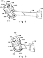
- Figs. 8 and 9 illustrate another movement dampened device which is a crowd control device 210 suitable for attachment on or within a self-standing post, or in a housing mounted on a wall or other structure.
- Crowd control device 210 includes a reel assembly 212 having a spool 214 and a web, rope, belt or strap 216 wound on the spool.
- a fixture 218 at the distal end of strap 216 can be secured to another structure or post of a similarly structured crowd control device, or to a simple receiving bracket made therefor, as those skilled in the art will readily understand.
- Reel assembly 212 includes a head 220, a base 222 and pillars 224 disposed between the head and the base.
- a cap plate 226 is connected to spool 214 to rotate therewith.
- a damper assembly 100 is mounted on cap plate 226 to move with plate 226 and spool 214.
- An internally toothed ring gear 228 is fixed to head 220, and does not move.
- Damper gear 108 engages ring gear 228 so that, as a spool 214, plate 226 and damper assembly 100 move, damper gear 108 revolves within ring gear 228 in driving engagement with the teeth of ring gear 228. Accordingly, the damping function of damper assembly 100 is transferred to the turning of spool 214 through the driving relationship of damper gear 108 and ring gear 228 and the connection of the damper assembly to the spool.
- Damper assembly 100 improves and promotes smooth consistent speed and acceleration so that wind up occurs with less random whipping, even if wind up is interfered with by catching or restraining of the strap as it winds.
- the damper moderates inconsistencies in speed and acceleration. If a one-way damper assembly is provided, damping control can be limited to the windup function, with unwinding being uninfluenced by the damper.
- damper engaging arrangements can be used also for connecting the damper assembly to a movement dampened device.
- Other gearing arrangements can be used whereby one of a cooperating gear from the device or the damper gear is fixed with respect to the nonmoving part of the device, such as a head or other portions of a crowd control device, and the other of the cooperating gear and the damper gear is affixed to, for rotation with the moving part of the device, such as a spool and/or other rotating parts of the reel assembly in a crowd control device. Accordingly, the controlling features of the damper are transferred to the moving parts of the device, such as the rollup feature of the spool in a crowd control device.
- damper assembly in crowd control devices
- damper assembly can be used in a wide variety of other structures and devices having moving parts, including those found in furniture, various automotive applications and devices of many other types.
Landscapes
- Engineering & Computer Science (AREA)
- General Engineering & Computer Science (AREA)
- Mechanical Engineering (AREA)
- Fluid-Damping Devices (AREA)
- Gear Transmission (AREA)
Applications Claiming Priority (3)
| Application Number | Priority Date | Filing Date | Title |
|---|---|---|---|
| US15449009P | 2009-02-23 | 2009-02-23 | |
| US22174809P | 2009-06-30 | 2009-06-30 | |
| PCT/US2010/021574 WO2010096229A1 (en) | 2009-02-23 | 2010-01-21 | Damper assembly and device utilizing the same |
Publications (3)
| Publication Number | Publication Date |
|---|---|
| EP2398678A1 EP2398678A1 (en) | 2011-12-28 |
| EP2398678A4 EP2398678A4 (en) | 2014-09-03 |
| EP2398678B1 true EP2398678B1 (en) | 2018-07-18 |
Family
ID=42634174
Family Applications (1)
| Application Number | Title | Priority Date | Filing Date |
|---|---|---|---|
| EP10744100.8A Not-in-force EP2398678B1 (en) | 2009-02-23 | 2010-01-21 | Damper assembly and device utilizing the same |
Country Status (5)
| Country | Link |
|---|---|
| US (1) | US9261158B2 (enExample) |
| EP (1) | EP2398678B1 (enExample) |
| JP (1) | JP5731410B2 (enExample) |
| CN (1) | CN102317125B (enExample) |
| WO (1) | WO2010096229A1 (enExample) |
Families Citing this family (10)
| Publication number | Priority date | Publication date | Assignee | Title |
|---|---|---|---|---|
| US20110120823A1 (en) * | 2009-11-20 | 2011-05-26 | Charles Hansen | Retracta Belt Brake System |
| US9273754B2 (en) * | 2012-02-27 | 2016-03-01 | Ford Global Technologies, Llc | Non-uniform axisymmetric driveline/axle damper |
| JP6570337B2 (ja) * | 2014-07-17 | 2019-09-04 | キヤノン株式会社 | 画像形成装置およびダンパ装置 |
| KR102211462B1 (ko) * | 2014-09-04 | 2021-02-03 | 현대모비스 주식회사 | 글로브박스 댐퍼 구조 |
| US10718145B2 (en) * | 2016-12-14 | 2020-07-21 | Ford Global Technologies, Llc | Viscous damper with integral spring |
| CN106920324B (zh) * | 2017-03-09 | 2023-03-28 | 深圳怡化电脑股份有限公司 | 传动装置、钞门结构及自动存取款机 |
| CN109972937B (zh) * | 2017-12-27 | 2022-05-10 | 伊利诺斯工具制品有限公司 | 加油或充电口门锁总成 |
| USD894719S1 (en) * | 2018-07-19 | 2020-09-01 | Adam Mills | Multi-position wall mounted barrier |
| CN111609051A (zh) * | 2020-06-28 | 2020-09-01 | 赣州禾盈通用零部件有限公司 | 一种塑料单向轴承阻尼器 |
| DE102020117520A1 (de) * | 2020-07-02 | 2022-01-05 | Illinois Tool Works Inc. | Vorrichtung und verfahren zur geräuschminderung eines lineardämpfers |
Family Cites Families (21)
| Publication number | Priority date | Publication date | Assignee | Title |
|---|---|---|---|---|
| JPS5010501A (enExample) | 1973-05-25 | 1975-02-03 | ||
| JPS5010501U (enExample) * | 1973-05-25 | 1975-02-03 | ||
| US4088281A (en) | 1976-10-13 | 1978-05-09 | American Safety Equipment Corporation | Dual tension single spring retractor |
| JPS56124532A (en) * | 1980-03-07 | 1981-09-30 | Takata Kk | Seat belt retractor with memory |
| US4576252A (en) | 1983-04-15 | 1986-03-18 | Nifco Inc. | Rotation damper |
| JPS6079032U (ja) * | 1983-11-07 | 1985-06-01 | 株式会社ニフコ | オイル式ダンパ− |
| US4527675A (en) * | 1984-04-19 | 1985-07-09 | Nifco Inc. | Oil type damper |
| JPS6124850A (ja) * | 1984-07-16 | 1986-02-03 | Nifco Inc | 一方向性ダンパ− |
| JPH023656Y2 (enExample) * | 1984-10-23 | 1990-01-29 | ||
| JP4467688B2 (ja) * | 1999-01-19 | 2010-05-26 | タカタ株式会社 | シートベルト巻取装置 |
| GB9903896D0 (en) | 1999-02-19 | 1999-04-14 | Tensator Ltd | A post for a queue management system |
| US6298960B1 (en) * | 2000-05-30 | 2001-10-09 | Illinois Tool Works Inc. | Small viscous precision damper |
| US6637567B2 (en) * | 2001-11-29 | 2003-10-28 | Illinois Tool Works Inc. | Free run clutch apparatus |
| DE10210917C1 (de) * | 2002-03-13 | 2003-11-13 | Itw Automotive Prod Gmbh & Co | Bremsvorrichtung mit Freilauf |
| US7152718B2 (en) * | 2002-04-16 | 2006-12-26 | Illinois Tool Works Inc | Damper |
| US6866588B2 (en) * | 2002-06-11 | 2005-03-15 | Illinois Tool Works Inc. | One-way damper |
| US6910557B2 (en) * | 2003-01-29 | 2005-06-28 | Illinois Tool Works Inc. | Slide damper with spring assist |
| US7350629B2 (en) * | 2004-11-18 | 2008-04-01 | Illinois Tool Works Inc. | Floating damper |
| US8079450B2 (en) | 2005-11-14 | 2011-12-20 | Illinois Tool Works Inc. | Viscous strand damper assembly |
| US20070108676A1 (en) * | 2005-11-14 | 2007-05-17 | Zeilenga Chad K | Viscous strand damper assembly |
| US20110120823A1 (en) | 2009-11-20 | 2011-05-26 | Charles Hansen | Retracta Belt Brake System |
-
2010
- 2010-01-21 EP EP10744100.8A patent/EP2398678B1/en not_active Not-in-force
- 2010-01-21 WO PCT/US2010/021574 patent/WO2010096229A1/en not_active Ceased
- 2010-01-21 JP JP2011551083A patent/JP5731410B2/ja not_active Expired - Fee Related
- 2010-01-21 US US13/202,178 patent/US9261158B2/en not_active Expired - Fee Related
- 2010-01-21 CN CN201080008003.XA patent/CN102317125B/zh not_active Expired - Fee Related
Non-Patent Citations (1)
| Title |
|---|
| None * |
Also Published As
| Publication number | Publication date |
|---|---|
| EP2398678A4 (en) | 2014-09-03 |
| JP2012518759A (ja) | 2012-08-16 |
| CN102317125B (zh) | 2015-07-01 |
| JP5731410B2 (ja) | 2015-06-10 |
| CN102317125A (zh) | 2012-01-11 |
| EP2398678A1 (en) | 2011-12-28 |
| WO2010096229A1 (en) | 2010-08-26 |
| US20110296938A1 (en) | 2011-12-08 |
| US9261158B2 (en) | 2016-02-16 |
Similar Documents
| Publication | Publication Date | Title |
|---|---|---|
| EP2398678B1 (en) | Damper assembly and device utilizing the same | |
| US4550470A (en) | Combined rotary damper device including a stored energy mechanism and braking mechanism | |
| EP3069938B1 (en) | Seat belt device | |
| US20090115115A1 (en) | Viscous strand damper assembly | |
| US9212731B2 (en) | Tensioner with multiple nested torsion springs | |
| JP4308699B2 (ja) | ウエビング巻取装置 | |
| US7152718B2 (en) | Damper | |
| JP2006213112A (ja) | プリテンショナ装置 | |
| US20150001331A1 (en) | Belt retractor with a recoil brake | |
| CN103568898B (zh) | 远程阻尼系统 | |
| JP2005271623A (ja) | ウエビング巻取装置 | |
| US20070108676A1 (en) | Viscous strand damper assembly | |
| US12304420B2 (en) | Belt retractor | |
| CN110566615A (zh) | 旋转式阻尼器蓄能自锁装置 | |
| KR100764754B1 (ko) | 시트벨트 리트랙터 | |
| KR100471682B1 (ko) | 관성작용을 이용한 안전 경첩 | |
| KR200487831Y1 (ko) | 롤 스크린용 감속모듈 | |
| JP4973567B2 (ja) | ドア位置規制装置 | |
| JP4020840B2 (ja) | 引戸の制動装置 | |
| JP4518891B2 (ja) | ウエビング巻取装置 | |
| JP4512500B2 (ja) | 回転部材のガタ止め構造及びウエビング巻取装置 | |
| JP2006213199A (ja) | ウエビング巻取装置 | |
| KR100188771B1 (ko) | 자동차의 안전벨트용 리트랙터 | |
| JP3246766B2 (ja) | 回転ダンパー | |
| JPH094624A (ja) | 締付ノブ |
Legal Events
| Date | Code | Title | Description |
|---|---|---|---|
| PUAI | Public reference made under article 153(3) epc to a published international application that has entered the european phase |
Free format text: ORIGINAL CODE: 0009012 |
|
| 17P | Request for examination filed |
Effective date: 20110727 |
|
| AK | Designated contracting states |
Kind code of ref document: A1 Designated state(s): AT BE BG CH CY CZ DE DK EE ES FI FR GB GR HR HU IE IS IT LI LT LU LV MC MK MT NL NO PL PT RO SE SI SK SM TR |
|
| DAX | Request for extension of the european patent (deleted) | ||
| RAP1 | Party data changed (applicant data changed or rights of an application transferred) |
Owner name: ILLINOIS TOOL WORKS INC. |
|
| REG | Reference to a national code |
Ref country code: DE Ref legal event code: R079 Ref document number: 602010051999 Country of ref document: DE Free format text: PREVIOUS MAIN CLASS: B60R0022440000 Ipc: F16F0009120000 |
|
| A4 | Supplementary search report drawn up and despatched |
Effective date: 20140806 |
|
| RIC1 | Information provided on ipc code assigned before grant |
Ipc: F16F 9/12 20060101AFI20140731BHEP |
|
| GRAP | Despatch of communication of intention to grant a patent |
Free format text: ORIGINAL CODE: EPIDOSNIGR1 |
|
| STAA | Information on the status of an ep patent application or granted ep patent |
Free format text: STATUS: GRANT OF PATENT IS INTENDED |
|
| INTG | Intention to grant announced |
Effective date: 20180319 |
|
| GRAS | Grant fee paid |
Free format text: ORIGINAL CODE: EPIDOSNIGR3 |
|
| GRAA | (expected) grant |
Free format text: ORIGINAL CODE: 0009210 |
|
| STAA | Information on the status of an ep patent application or granted ep patent |
Free format text: STATUS: THE PATENT HAS BEEN GRANTED |
|
| AK | Designated contracting states |
Kind code of ref document: B1 Designated state(s): AT BE BG CH CY CZ DE DK EE ES FI FR GB GR HR HU IE IS IT LI LT LU LV MC MK MT NL NO PL PT RO SE SI SK SM TR |
|
| REG | Reference to a national code |
Ref country code: GB Ref legal event code: FG4D |
|
| REG | Reference to a national code |
Ref country code: CH Ref legal event code: EP |
|
| REG | Reference to a national code |
Ref country code: IE Ref legal event code: FG4D |
|
| REG | Reference to a national code |
Ref country code: AT Ref legal event code: REF Ref document number: 1019698 Country of ref document: AT Kind code of ref document: T Effective date: 20180815 |
|
| REG | Reference to a national code |
Ref country code: DE Ref legal event code: R096 Ref document number: 602010051999 Country of ref document: DE |
|
| REG | Reference to a national code |
Ref country code: NL Ref legal event code: MP Effective date: 20180718 |
|
| REG | Reference to a national code |
Ref country code: LT Ref legal event code: MG4D |
|
| REG | Reference to a national code |
Ref country code: AT Ref legal event code: MK05 Ref document number: 1019698 Country of ref document: AT Kind code of ref document: T Effective date: 20180718 |
|
| PG25 | Lapsed in a contracting state [announced via postgrant information from national office to epo] |
Ref country code: NL Free format text: LAPSE BECAUSE OF FAILURE TO SUBMIT A TRANSLATION OF THE DESCRIPTION OR TO PAY THE FEE WITHIN THE PRESCRIBED TIME-LIMIT Effective date: 20180718 |
|
| PG25 | Lapsed in a contracting state [announced via postgrant information from national office to epo] |
Ref country code: FI Free format text: LAPSE BECAUSE OF FAILURE TO SUBMIT A TRANSLATION OF THE DESCRIPTION OR TO PAY THE FEE WITHIN THE PRESCRIBED TIME-LIMIT Effective date: 20180718 Ref country code: PL Free format text: LAPSE BECAUSE OF FAILURE TO SUBMIT A TRANSLATION OF THE DESCRIPTION OR TO PAY THE FEE WITHIN THE PRESCRIBED TIME-LIMIT Effective date: 20180718 Ref country code: SE Free format text: LAPSE BECAUSE OF FAILURE TO SUBMIT A TRANSLATION OF THE DESCRIPTION OR TO PAY THE FEE WITHIN THE PRESCRIBED TIME-LIMIT Effective date: 20180718 Ref country code: BG Free format text: LAPSE BECAUSE OF FAILURE TO SUBMIT A TRANSLATION OF THE DESCRIPTION OR TO PAY THE FEE WITHIN THE PRESCRIBED TIME-LIMIT Effective date: 20181018 Ref country code: AT Free format text: LAPSE BECAUSE OF FAILURE TO SUBMIT A TRANSLATION OF THE DESCRIPTION OR TO PAY THE FEE WITHIN THE PRESCRIBED TIME-LIMIT Effective date: 20180718 Ref country code: IS Free format text: LAPSE BECAUSE OF FAILURE TO SUBMIT A TRANSLATION OF THE DESCRIPTION OR TO PAY THE FEE WITHIN THE PRESCRIBED TIME-LIMIT Effective date: 20181118 Ref country code: GR Free format text: LAPSE BECAUSE OF FAILURE TO SUBMIT A TRANSLATION OF THE DESCRIPTION OR TO PAY THE FEE WITHIN THE PRESCRIBED TIME-LIMIT Effective date: 20181019 Ref country code: NO Free format text: LAPSE BECAUSE OF FAILURE TO SUBMIT A TRANSLATION OF THE DESCRIPTION OR TO PAY THE FEE WITHIN THE PRESCRIBED TIME-LIMIT Effective date: 20181018 Ref country code: LT Free format text: LAPSE BECAUSE OF FAILURE TO SUBMIT A TRANSLATION OF THE DESCRIPTION OR TO PAY THE FEE WITHIN THE PRESCRIBED TIME-LIMIT Effective date: 20180718 |
|
| PG25 | Lapsed in a contracting state [announced via postgrant information from national office to epo] |
Ref country code: HR Free format text: LAPSE BECAUSE OF FAILURE TO SUBMIT A TRANSLATION OF THE DESCRIPTION OR TO PAY THE FEE WITHIN THE PRESCRIBED TIME-LIMIT Effective date: 20180718 Ref country code: LV Free format text: LAPSE BECAUSE OF FAILURE TO SUBMIT A TRANSLATION OF THE DESCRIPTION OR TO PAY THE FEE WITHIN THE PRESCRIBED TIME-LIMIT Effective date: 20180718 Ref country code: ES Free format text: LAPSE BECAUSE OF FAILURE TO SUBMIT A TRANSLATION OF THE DESCRIPTION OR TO PAY THE FEE WITHIN THE PRESCRIBED TIME-LIMIT Effective date: 20180718 |
|
| REG | Reference to a national code |
Ref country code: DE Ref legal event code: R097 Ref document number: 602010051999 Country of ref document: DE |
|
| PG25 | Lapsed in a contracting state [announced via postgrant information from national office to epo] |
Ref country code: CZ Free format text: LAPSE BECAUSE OF FAILURE TO SUBMIT A TRANSLATION OF THE DESCRIPTION OR TO PAY THE FEE WITHIN THE PRESCRIBED TIME-LIMIT Effective date: 20180718 Ref country code: RO Free format text: LAPSE BECAUSE OF FAILURE TO SUBMIT A TRANSLATION OF THE DESCRIPTION OR TO PAY THE FEE WITHIN THE PRESCRIBED TIME-LIMIT Effective date: 20180718 Ref country code: EE Free format text: LAPSE BECAUSE OF FAILURE TO SUBMIT A TRANSLATION OF THE DESCRIPTION OR TO PAY THE FEE WITHIN THE PRESCRIBED TIME-LIMIT Effective date: 20180718 Ref country code: IT Free format text: LAPSE BECAUSE OF FAILURE TO SUBMIT A TRANSLATION OF THE DESCRIPTION OR TO PAY THE FEE WITHIN THE PRESCRIBED TIME-LIMIT Effective date: 20180718 |
|
| PLBE | No opposition filed within time limit |
Free format text: ORIGINAL CODE: 0009261 |
|
| STAA | Information on the status of an ep patent application or granted ep patent |
Free format text: STATUS: NO OPPOSITION FILED WITHIN TIME LIMIT |
|
| PG25 | Lapsed in a contracting state [announced via postgrant information from national office to epo] |
Ref country code: DK Free format text: LAPSE BECAUSE OF FAILURE TO SUBMIT A TRANSLATION OF THE DESCRIPTION OR TO PAY THE FEE WITHIN THE PRESCRIBED TIME-LIMIT Effective date: 20180718 Ref country code: SM Free format text: LAPSE BECAUSE OF FAILURE TO SUBMIT A TRANSLATION OF THE DESCRIPTION OR TO PAY THE FEE WITHIN THE PRESCRIBED TIME-LIMIT Effective date: 20180718 Ref country code: SK Free format text: LAPSE BECAUSE OF FAILURE TO SUBMIT A TRANSLATION OF THE DESCRIPTION OR TO PAY THE FEE WITHIN THE PRESCRIBED TIME-LIMIT Effective date: 20180718 |
|
| 26N | No opposition filed |
Effective date: 20190423 |
|
| PG25 | Lapsed in a contracting state [announced via postgrant information from national office to epo] |
Ref country code: SI Free format text: LAPSE BECAUSE OF FAILURE TO SUBMIT A TRANSLATION OF THE DESCRIPTION OR TO PAY THE FEE WITHIN THE PRESCRIBED TIME-LIMIT Effective date: 20180718 Ref country code: MC Free format text: LAPSE BECAUSE OF FAILURE TO SUBMIT A TRANSLATION OF THE DESCRIPTION OR TO PAY THE FEE WITHIN THE PRESCRIBED TIME-LIMIT Effective date: 20180718 |
|
| REG | Reference to a national code |
Ref country code: CH Ref legal event code: PL |
|
| GBPC | Gb: european patent ceased through non-payment of renewal fee |
Effective date: 20190121 |
|
| PG25 | Lapsed in a contracting state [announced via postgrant information from national office to epo] |
Ref country code: LU Free format text: LAPSE BECAUSE OF NON-PAYMENT OF DUE FEES Effective date: 20190121 |
|
| REG | Reference to a national code |
Ref country code: BE Ref legal event code: MM Effective date: 20190131 |
|
| REG | Reference to a national code |
Ref country code: IE Ref legal event code: MM4A |
|
| PG25 | Lapsed in a contracting state [announced via postgrant information from national office to epo] |
Ref country code: FR Free format text: LAPSE BECAUSE OF NON-PAYMENT OF DUE FEES Effective date: 20190131 |
|
| PG25 | Lapsed in a contracting state [announced via postgrant information from national office to epo] |
Ref country code: BE Free format text: LAPSE BECAUSE OF NON-PAYMENT OF DUE FEES Effective date: 20190131 |
|
| PG25 | Lapsed in a contracting state [announced via postgrant information from national office to epo] |
Ref country code: GB Free format text: LAPSE BECAUSE OF NON-PAYMENT OF DUE FEES Effective date: 20190121 Ref country code: LI Free format text: LAPSE BECAUSE OF NON-PAYMENT OF DUE FEES Effective date: 20190131 Ref country code: CH Free format text: LAPSE BECAUSE OF NON-PAYMENT OF DUE FEES Effective date: 20190131 |
|
| PG25 | Lapsed in a contracting state [announced via postgrant information from national office to epo] |
Ref country code: IE Free format text: LAPSE BECAUSE OF NON-PAYMENT OF DUE FEES Effective date: 20190121 |
|
| PG25 | Lapsed in a contracting state [announced via postgrant information from national office to epo] |
Ref country code: TR Free format text: LAPSE BECAUSE OF FAILURE TO SUBMIT A TRANSLATION OF THE DESCRIPTION OR TO PAY THE FEE WITHIN THE PRESCRIBED TIME-LIMIT Effective date: 20180718 |
|
| PG25 | Lapsed in a contracting state [announced via postgrant information from national office to epo] |
Ref country code: PT Free format text: LAPSE BECAUSE OF FAILURE TO SUBMIT A TRANSLATION OF THE DESCRIPTION OR TO PAY THE FEE WITHIN THE PRESCRIBED TIME-LIMIT Effective date: 20181118 Ref country code: MT Free format text: LAPSE BECAUSE OF NON-PAYMENT OF DUE FEES Effective date: 20190121 |
|
| PG25 | Lapsed in a contracting state [announced via postgrant information from national office to epo] |
Ref country code: CY Free format text: LAPSE BECAUSE OF FAILURE TO SUBMIT A TRANSLATION OF THE DESCRIPTION OR TO PAY THE FEE WITHIN THE PRESCRIBED TIME-LIMIT Effective date: 20180718 |
|
| PG25 | Lapsed in a contracting state [announced via postgrant information from national office to epo] |
Ref country code: HU Free format text: LAPSE BECAUSE OF FAILURE TO SUBMIT A TRANSLATION OF THE DESCRIPTION OR TO PAY THE FEE WITHIN THE PRESCRIBED TIME-LIMIT; INVALID AB INITIO Effective date: 20100121 |
|
| PGFP | Annual fee paid to national office [announced via postgrant information from national office to epo] |
Ref country code: DE Payment date: 20220127 Year of fee payment: 13 |
|
| PG25 | Lapsed in a contracting state [announced via postgrant information from national office to epo] |
Ref country code: MK Free format text: LAPSE BECAUSE OF FAILURE TO SUBMIT A TRANSLATION OF THE DESCRIPTION OR TO PAY THE FEE WITHIN THE PRESCRIBED TIME-LIMIT Effective date: 20180718 |
|
| REG | Reference to a national code |
Ref country code: DE Ref legal event code: R119 Ref document number: 602010051999 Country of ref document: DE |
|
| PG25 | Lapsed in a contracting state [announced via postgrant information from national office to epo] |
Ref country code: DE Free format text: LAPSE BECAUSE OF NON-PAYMENT OF DUE FEES Effective date: 20230801 |