EP2397786B1 - Sekundärpumpen-wärmequellensystem und sekundärpumpen-wärmequellensteuerverfahren - Google Patents
Sekundärpumpen-wärmequellensystem und sekundärpumpen-wärmequellensteuerverfahren Download PDFInfo
- Publication number
- EP2397786B1 EP2397786B1 EP10741193.6A EP10741193A EP2397786B1 EP 2397786 B1 EP2397786 B1 EP 2397786B1 EP 10741193 A EP10741193 A EP 10741193A EP 2397786 B1 EP2397786 B1 EP 2397786B1
- Authority
- EP
- European Patent Office
- Prior art keywords
- heat source
- water
- load system
- flow quantity
- heat
- Prior art date
- Legal status (The legal status is an assumption and is not a legal conclusion. Google has not performed a legal analysis and makes no representation as to the accuracy of the status listed.)
- Active
Links
Images


Classifications
-
- F—MECHANICAL ENGINEERING; LIGHTING; HEATING; WEAPONS; BLASTING
- F24—HEATING; RANGES; VENTILATING
- F24F—AIR-CONDITIONING; AIR-HUMIDIFICATION; VENTILATION; USE OF AIR CURRENTS FOR SCREENING
- F24F11/00—Control or safety arrangements
- F24F11/70—Control systems characterised by their outputs; Constructional details thereof
- F24F11/80—Control systems characterised by their outputs; Constructional details thereof for controlling the temperature of the supplied air
- F24F11/83—Control systems characterised by their outputs; Constructional details thereof for controlling the temperature of the supplied air by controlling the supply of heat-exchange fluids to heat-exchangers
- F24F11/85—Control systems characterised by their outputs; Constructional details thereof for controlling the temperature of the supplied air by controlling the supply of heat-exchange fluids to heat-exchangers using variable-flow pumps
-
- F—MECHANICAL ENGINEERING; LIGHTING; HEATING; WEAPONS; BLASTING
- F24—HEATING; RANGES; VENTILATING
- F24F—AIR-CONDITIONING; AIR-HUMIDIFICATION; VENTILATION; USE OF AIR CURRENTS FOR SCREENING
- F24F11/00—Control or safety arrangements
- F24F11/70—Control systems characterised by their outputs; Constructional details thereof
- F24F11/80—Control systems characterised by their outputs; Constructional details thereof for controlling the temperature of the supplied air
- F24F11/83—Control systems characterised by their outputs; Constructional details thereof for controlling the temperature of the supplied air by controlling the supply of heat-exchange fluids to heat-exchangers
-
- F—MECHANICAL ENGINEERING; LIGHTING; HEATING; WEAPONS; BLASTING
- F24—HEATING; RANGES; VENTILATING
- F24F—AIR-CONDITIONING; AIR-HUMIDIFICATION; VENTILATION; USE OF AIR CURRENTS FOR SCREENING
- F24F3/00—Air-conditioning systems in which conditioned primary air is supplied from one or more central stations to distributing units in the rooms or spaces where it may receive secondary treatment; Apparatus specially designed for such systems
- F24F3/06—Air-conditioning systems in which conditioned primary air is supplied from one or more central stations to distributing units in the rooms or spaces where it may receive secondary treatment; Apparatus specially designed for such systems characterised by the arrangements for the supply of heat-exchange fluid for the subsequent treatment of primary air in the room units
- F24F3/065—Air-conditioning systems in which conditioned primary air is supplied from one or more central stations to distributing units in the rooms or spaces where it may receive secondary treatment; Apparatus specially designed for such systems characterised by the arrangements for the supply of heat-exchange fluid for the subsequent treatment of primary air in the room units with a plurality of evaporators or condensers
-
- F—MECHANICAL ENGINEERING; LIGHTING; HEATING; WEAPONS; BLASTING
- F25—REFRIGERATION OR COOLING; COMBINED HEATING AND REFRIGERATION SYSTEMS; HEAT PUMP SYSTEMS; MANUFACTURE OR STORAGE OF ICE; LIQUEFACTION SOLIDIFICATION OF GASES
- F25B—REFRIGERATION MACHINES, PLANTS OR SYSTEMS; COMBINED HEATING AND REFRIGERATION SYSTEMS; HEAT PUMP SYSTEMS
- F25B25/00—Machines, plants or systems, using a combination of modes of operation covered by two or more of the groups F25B1/00 - F25B23/00
- F25B25/005—Machines, plants or systems, using a combination of modes of operation covered by two or more of the groups F25B1/00 - F25B23/00 using primary and secondary systems
-
- F—MECHANICAL ENGINEERING; LIGHTING; HEATING; WEAPONS; BLASTING
- F24—HEATING; RANGES; VENTILATING
- F24F—AIR-CONDITIONING; AIR-HUMIDIFICATION; VENTILATION; USE OF AIR CURRENTS FOR SCREENING
- F24F2140/00—Control inputs relating to system states
- F24F2140/20—Heat-exchange fluid temperature
-
- F—MECHANICAL ENGINEERING; LIGHTING; HEATING; WEAPONS; BLASTING
- F25—REFRIGERATION OR COOLING; COMBINED HEATING AND REFRIGERATION SYSTEMS; HEAT PUMP SYSTEMS; MANUFACTURE OR STORAGE OF ICE; LIQUEFACTION SOLIDIFICATION OF GASES
- F25B—REFRIGERATION MACHINES, PLANTS OR SYSTEMS; COMBINED HEATING AND REFRIGERATION SYSTEMS; HEAT PUMP SYSTEMS
- F25B13/00—Compression machines, plants or systems, with reversible cycle
-
- F—MECHANICAL ENGINEERING; LIGHTING; HEATING; WEAPONS; BLASTING
- F25—REFRIGERATION OR COOLING; COMBINED HEATING AND REFRIGERATION SYSTEMS; HEAT PUMP SYSTEMS; MANUFACTURE OR STORAGE OF ICE; LIQUEFACTION SOLIDIFICATION OF GASES
- F25B—REFRIGERATION MACHINES, PLANTS OR SYSTEMS; COMBINED HEATING AND REFRIGERATION SYSTEMS; HEAT PUMP SYSTEMS
- F25B2313/00—Compression machines, plants or systems with reversible cycle not otherwise provided for
- F25B2313/003—Indoor unit with water as a heat sink or heat source
-
- F—MECHANICAL ENGINEERING; LIGHTING; HEATING; WEAPONS; BLASTING
- F25—REFRIGERATION OR COOLING; COMBINED HEATING AND REFRIGERATION SYSTEMS; HEAT PUMP SYSTEMS; MANUFACTURE OR STORAGE OF ICE; LIQUEFACTION SOLIDIFICATION OF GASES
- F25B—REFRIGERATION MACHINES, PLANTS OR SYSTEMS; COMBINED HEATING AND REFRIGERATION SYSTEMS; HEAT PUMP SYSTEMS
- F25B2400/00—General features or devices for refrigeration machines, plants or systems, combined heating and refrigeration systems or heat-pump systems, i.e. not limited to a particular subgroup of F25B
- F25B2400/06—Several compression cycles arranged in parallel
-
- F—MECHANICAL ENGINEERING; LIGHTING; HEATING; WEAPONS; BLASTING
- F25—REFRIGERATION OR COOLING; COMBINED HEATING AND REFRIGERATION SYSTEMS; HEAT PUMP SYSTEMS; MANUFACTURE OR STORAGE OF ICE; LIQUEFACTION SOLIDIFICATION OF GASES
- F25B—REFRIGERATION MACHINES, PLANTS OR SYSTEMS; COMBINED HEATING AND REFRIGERATION SYSTEMS; HEAT PUMP SYSTEMS
- F25B2500/00—Problems to be solved
- F25B2500/19—Calculation of parameters
-
- F—MECHANICAL ENGINEERING; LIGHTING; HEATING; WEAPONS; BLASTING
- F25—REFRIGERATION OR COOLING; COMBINED HEATING AND REFRIGERATION SYSTEMS; HEAT PUMP SYSTEMS; MANUFACTURE OR STORAGE OF ICE; LIQUEFACTION SOLIDIFICATION OF GASES
- F25B—REFRIGERATION MACHINES, PLANTS OR SYSTEMS; COMBINED HEATING AND REFRIGERATION SYSTEMS; HEAT PUMP SYSTEMS
- F25B2600/00—Control issues
- F25B2600/13—Pump speed control
-
- Y—GENERAL TAGGING OF NEW TECHNOLOGICAL DEVELOPMENTS; GENERAL TAGGING OF CROSS-SECTIONAL TECHNOLOGIES SPANNING OVER SEVERAL SECTIONS OF THE IPC; TECHNICAL SUBJECTS COVERED BY FORMER USPC CROSS-REFERENCE ART COLLECTIONS [XRACs] AND DIGESTS
- Y02—TECHNOLOGIES OR APPLICATIONS FOR MITIGATION OR ADAPTATION AGAINST CLIMATE CHANGE
- Y02B—CLIMATE CHANGE MITIGATION TECHNOLOGIES RELATED TO BUILDINGS, e.g. HOUSING, HOUSE APPLIANCES OR RELATED END-USER APPLICATIONS
- Y02B30/00—Energy efficient heating, ventilation or air conditioning [HVAC]
- Y02B30/70—Efficient control or regulation technologies, e.g. for control of refrigerant flow, motor or heating
Definitions
- the present invention relates to a secondary pump-type heat source system and a method of controlling the secondary pump-type heat source system.
- a heat source system In the case where a plurality of indoor systems (fan coil units) are installed in a place such as a large-scale factory or building, for example, a heat source system has been used in which heat source water (cold or hot water) is supplied from a heat source to these indoor systems for air conditioning of plural air-conditioning areas.
- This heat source system is roughly separated into a heat source side and a load system side (an indoor system side), which are connected to each other through a water supply pipe and a water return pipe to form one circuit.
- the water supply pipe heat source water is supplied from the heat source to a load system, and by the water return pipe, the heat source water is returned through the load system to the heat source again.
- the heat source water subjected to heat exchange within the heat source is supplied by a primary pump through the water supply pipe to the load systems such as air conditioning systems or fan coils.
- This heat source water is subjected to heat exchange within the load systems and then supplied to the secondary pump through the water return pipe.
- the heat source water supplied to the secondary pumps goes through the heat source again, thus circulating in the circuit.
- the heat source system is provided with a bypass pipe which bypasses the water supply and return pipes between the heat source side and load system side in order to cope with imbalance between the flow quantity of heat source water flowing in the heat source side and the flow quantity of heat source water flowing in the load system side.
- Patent Literature 3 it is disclosed to unrequire a flowmeter and to increase economy in investment by multiplying the total value of operation rated capacities of the cool and hot water apparatuses to the temperature difference between outgoing wager and return water to obtain an approximate quantity of heat consumed of a load apparatus, and controlling the number of apparatuses to be operated in accordance with the quantity of heat to be Patent Literature 3 thereby discloses a secondary pump-type heat source system as defined in claim 1 and a method of controlling such a system as defined in claim 2.
- the present invention was made to solve the aforementioned problem, and an object of the present invention is to provide a secondary pump-type heat source system and a secondary pump-type heat source controlling method which are capable of properly responding to changes in the load system side without a flow meter and performing an efficient control to contribute to energy saving.
- a secondary pump-type heat source system with the features of claim 1.
- Said secondary pump-type heat source system including: a plurality of heat sources which are connected in parallel and generate heat source water; a load system in which the heat source water flows; a primary pump supplying the heat source water to the load system; a water supply pipe connecting an outlet of the heat source and the load system; a secondary pump which is provided for each heat source and supplies the heat source water subjected to heat exchange in the load system to the heat source; a water return pipe connecting the outlet of the load system and the secondary pumps; a bypass pipe allowing the water supply pipe and the water return pipe to communicate with each other; a water temperature sensor detecting temperature of the heat source water; and a heat source controller calculating flow quantity of the heat source water flowing in the heat source side and flow quantity of the heat source water flowing in the load system side by assigning a result from measurement by the water temperature sensor to an operation characteristic of each of the heat sources and controlling operation of the secondary pumps based on
- a method of controlling a secondary pump-type heat source including: a plurality of heat sources which are connected in parallel and generate heat source water; a load system in which the heat source water flows; a primary pump supplying the heat source water to the load system; a water supply pipe connecting an outlet of the heat source and the load system; a secondary pump which is provided for each heat source and supplies the heat source water subjected to heat exchange in the load system to the heat source; a water return pipe connecting the outlet of the load system and the secondary pumps; and a bypass pipe allowing the water supply pipe and the water return pipe to communicate with each other.
- the method includes: calculating flow quantity of the heat source water flowing in the heat source side and flow quantity of the heat source water flowing in the load system side based on the temperature of the heat source water; and determining whether to increase or decrease the number of secondary pumps in operation to reduce a difference between the flow quantity in the heat source side and the flow quantity in the load system side based on the calculated flow quantities in the heat source side and load system side.
- a preferred embodiment is defined in claim 3.
- a secondary pump-type heat source system and a method of controlling the secondary pump-type heat source system which are capable of accurately responding to changes in the load system side without flow meters and performing high efficiency control to contribute energy saving.
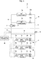
- FIG. 1 is an entire view showing a secondary pump-type heat source system S according to the embodiment of the present invention.
- the secondary pump-type heat source system S is roughly separated into a heat source side A and a load system side B as indicated by a dashed line of FIG. 1 .
- heat sources 1 generating heat source water and secondary pumps (heat source side pumps) 2 supplying circulated heat source water to the heat sources 1 are provided.
- Each heat source 1 includes a compressor, a four-way valve, a heat exchanger, a throttle mechanism, and a water heat exchanger, which are connected with pipes and not shown in the drawings.
- the pipes are filled with a refrigerant.
- the refrigerant circulates sequentially in the compressor, heat exchanger, throttle mechanism, and water heat exchanger, thus constituting a refrigerant circuit.
- the compressor sucks and compresses the refrigerant and discharges the refrigerant at high temperature and pressure.
- An end of the compressor on the discharge side is connected to the heat exchanger including a fan.
- the refrigerant exchanges heat with air through ventilation by the fan.
- the water heat exchanger is connected to the throttle mechanism, and the refrigerant going through the throttle mechanism then passes through the water heat exchanger.
- the refrigerant exchanges heat with water flowing through a pipe separately connected to the water heat exchanger to generate heat source water. The refrigerant then enters the compressor again.
- the four-way valve is switched to reverse the flow of the refrigerant, so that the refrigerant discharged from the compressor flows through the water heat exchanger, throttle mechanism, and heat exchanger and then returns to the compressor.
- the heat source therefore generates any of cold water for cooling/refrigeration and hot water for heating/warming.
- the secondary pumps 2 supplying heat source water to the heat sources 1 are individually provided for the respective heat sources 1.
- the secondary pumps 2 are connected to respective secondary pump inverters 3 and are operated by the secondary pump inverters 3 based on an instruction from a later-described heat source controller so as to change in speed.
- the secondary pumps 2 have a same specification (an input-flow quantity characteristic). Moreover, in order to simplify the control, the performances of the secondary pumps 2 in operation or outputs of the secondary pump inverters 3 are controlled so as to be the same.
- Heat source inlet and outlet water temperature sensors 4 and 5 are connected to around the inlet and outlet of each heat source 1, respectively.
- the heat source inlet water temperature sensor 4 measures temperature of heat source water to be supplied to the heat source 1.
- the heat source outlet water temperature sensor 5 measures temperature of heat source water discharged from the heat source 1 to be supplied to the load systems.
- each heat source 1 is necessarily connected to one of the secondary pumps 2, the number of heat sources 1 is the same as the number of secondary pumps 2.
- each secondary pump 2 is connected to one of the secondary pump inverters 3.
- Each heat source 1 is connected to the corresponding heat source inlet and outlet water temperature sensors 4 and 5 as described above.
- the heat source 1, secondary pump 2, secondary pump inverter 3, heat source inlet and outlet water temperature sensors 4 and 5 are collectively referred to as a heat source unit.
- the heat source water generated in the heat sources 1 is supplied to the load system side B through a water supply pipe 6 with an end connected to the outlet of each heat source 1.
- the other end of the water supply pipe 6 is connected to a primary pump (load-side pump) 7 and a primary pump inverter 8 controlling the primary pump 7.
- the heat source water is thus fed to load systems 9.
- the primary pump 7 is driven by the primary pump inverter 8 so as to change in speed so that the flow quantity of the heat source water to be supplied to the load systems 9 is controlled.
- the output (flow quantity) of the primary pump 7 is controlled according to the cooling and heating performance required by the load systems 9 independently of the operation in the heat source side.
- the load systems 9 are air conditioners such as fan coils, for example.
- FIG. 1 two load systems 9a and 9b are connected in parallel (hereinafter, the load systems 9a and 9b are collectively referred to as the load systems 9).
- the number of load systems 9 connected may be any number.
- the heat source water subjected to heat exchange in the load systems 9 flows in a water return pipe 11 through two-way valves 10 connected to the outlet of each load systems 9 to be fed to the secondary pumps 2 in the heat source side A.
- a supply water temperature sensor 12 measuring temperature of heat source water flowing in the water supply pipe 6 is provided.
- a return water temperature sensor 13 measuring temperature of heat source water flowing in the water return pipe 11 is provided.
- a bypass pipe 14 is provided so as to allow the water supply pipe 6 between the heat sources 1 and supply water temperature sensor 12 to communicate with the water return pipe 11 between the return water temperature sensor 13 and secondary pumps 2.
- the return water temperature sensor 13 is attached to the water return pipe 11 at the load system 9 side of the connection between the water return pipe 11 and bypass pipe 14, and the supply water temperature sensor 12 is attached to the water supply pipe 6 on the load system 9 side of the connection between the water supply pipe 6 and bypass pipe 14.
- the heat source controller 15 is a controller configured to operate and control each device installed in the heat source side A.
- the three heat sources 1 connected, for example, are individually operated and controlled based on an instruction from the heat source controller 15.
- the measurement results from the supply and return water temperature sensors 12 and 13 are collected to the heat source controller 15, and information on temperature measured by the heat source inlet and outlet water temperature sensors 4 and 5 are also collected to the heat source controller 15 through the heat sources 1.
- FIG. 2 is a block diagram showing an internal configuration of the heat source controller 15.
- the heat source controller 15 includes a reception unit 15a, a storage unit 15b, a calculation unit 15c, a control unit 15d, an instruction creation unit 15e, and a transmission unit 15f.
- the reception unit 15a receives water temperature information from the temperature sensors, including the supply and return water temperature sensors 12 and 13 and the heat source inlet and outlet water temperature sensors 4 and 5 of each heat source 1 through the heat source 1, for example.
- the storage unit 15b stores equations expressing operating characteristics of the heat sources 1 to be subjected to later-described control.
- the calculation unit 15c assigns the measurement result transmitted from each temperature sensor to the equations stored in the storage unit 15b to calculate the flow quantity of heat source water flowing in the heat source side A and the flow quantity of heat source water flowing in the load system side B.
- the control unit 15d makes a control instruction for each heat source 1 or each secondary pump 2 based on the result calculated by the calculation unit 15c.
- the instruction creation unit 15e creates an actual instruction to each heat source 1 based on the instruction from the control unit 15d.
- the transmission unit 15f plays a role of transmitting the instruction to each heat source 1 and the inverter 3 of each secondary pump 2.
- FIG. 3 is a flowchart roughly showing a flow concerning the method of controlling the secondary pump-type heat source system S.
- the control of the secondary pump-type heat source system S is performed roughly in two steps.
- the first step (ST1) the total flow quantity of heat source water flowing in the load system side B is calculated.
- the second step (ST2) based on the calculated flow quantities in the heat source and load system sides A and B, the heat source controller 15 determines the performances (flow quantities) of the secondary pumps 2 and whether to increase or decrease the number of secondary pumps 2 in operation so as to minimize the difference between the flow quantities in the heat source side A and load system side B and controls the secondary pump inverters 3.
- the flowchart shown in FIG. 4 is to describe the flow (ST1) of calculating the total flow quantity of the heat source water flowing in the load system side B in detail.
- the performance of each heat source 1 is calculated (ST11).
- the installed heat sources 1 are not necessarily devices of a same type. Even if the heat sources 1 are devices of a same type, the heat sources 1 have slightly different performances in many cases. Accordingly, the performance of each heat source 1 is recognized at first.
- each heat source 1 is operated, and the freezing or heating performance is calculated based on the saturated condensing temperature and saturated evaporating temperature.
- the heat sources 1 are experimentally operated in advance, and the relation among the operating performance, saturated condensing temperature, and saturated evaporating temperature is obtained and expressed as an equation, for example. Since such equations are stored in the storage unit 15b, the calculation unit 15c can calculate the performances of the heat sources 1 upon receiving the information concerning the saturated condensing temperature and saturated evaporating temperature from the heat sources 1.
- the flow quantity of heat source water flowing in each heat source 1 is calculated using the following equation (ST12).
- the temperature information measured by the heat source inlet and outlet water sensors 4 and 5 is received by the reception unit 15a and is then transmitted to the calculation unit 15c.
- the calculation unit 15c extracts an equation stored in the storage unit 15b according to the operating state of the heat source 1 and assigns the temperature information measured by the heat source inlet and outlet water sensors 4 and 5 to the extracted equation to calculate the flow quantity of heat source water flowing in the heat source 1.
- This calculation of the flow quantity is performed for each heat source 1 (each heat source unit) connected to the secondary pump-type heat source system S. Accordingly, it is possible to know the individual flow quantity of each heat source 1 (each heat source unit).
- Equation 1 is flow quantity of heat source water flowing through each heat source 1 (liter/min); Wc, freezing performance of the heat source 1 (kW); Wh, heating performance of the heat source 1 (kW); Te, water temperature (°C) measured at the heat source inlet by the heat source inlet water temperature sensor 4; and T1, water temperature measured (°C) at the heat source outlet by the heat source outlet water temperature sensor 5.
- q 860 W c T e ⁇ T 1 / 60
- q 860 W h T 1 ⁇ T e / 60
- the heat sources 1 generate heat source water based on return water fed from the secondary pumps 2. This is carried out because both of the heat source 1 and secondary pump 2 of a same heat source unit are in operation. In such a case, the flow quantity of heat source water flowing through the heat source of interest can be calculated.
- the flow quantities q calculated for the heat source units in which both of the heat source 1 and secondary pump 2 are in operation are added up.
- the flow quantity calculated by the addition is divided by the number of heat source units in which the heat source 1 and secondary pump 2 are both in operation, thus calculating the average flow quantity of heat source water flowing in the heat sources 1 of the heat source units in which the heat source 1 and secondary pump 2 are both in operation.
- This average flow quantity is considered as the flow quantity q in a heat source unit in which the secondary pump 2 is in operation while the heat source 1 is not in operation.
- all of the secondary pumps 2 are configured to have a same specification, and the inverters 3 driving the secondary pumps 2 in operation are configured to have a same output frequency. Accordingly, there is no large error even if the secondary pump 2 is assumed to be in operation with the average flow quantity of heat source water flowing through the heat sources 1 of the operating heat source units and the average flow quantity is assumed to be the flow quantity in the heat source unit in which the heat source 1 is not in operation.
- the flow quantities q of the heat sources 1 which are calculated through the above-described calculation by the calculation unit 15c are added up by the calculation unit 15c to calculate total flow quantity Q1 of heat source water flowing in the heat source side A (ST13).
- the calculation unit 15c receives through the reception unit 15a the information concerning the inlet and outlet water temperatures measured by the heat source inlet and outlet water temperature sensors 4 and 5 and calculates the averages.
- the averages of the inlet and outlet water temperatures of the heat sources 1 are calculated as described above because the averages are necessary for calculating the flow quantity of heat source water flowing in the load system side B without using a flow meter.
- the inlet and outlet water temperatures used to calculate the averages are limited to temperatures measured by the heat source inlet and outlet temperature sensors 4 and 5 of the heat source units in which the secondary pumps 2 are in operation. This is because the heat source water flows through the water supply pipe 6 to be supplied to the load system side B when the secondary pumps 2 are in operation regardless of whether the heat sources 1 are in operation.
- the average outlet water temperature of the heat sources 1 calculated by the calculation unit 15c is transmitted to the control unit 15d.
- the controller 15d collects also the information concerning the temperature of supply water measured by the supply water temperature sensor 12.
- the control unit 15d compares the average outlet water temperature with the supply water temperature (ST15).
- the average outlet water temperature is equal to the temperature of supply water (YES in ST16)
- heat source water discharged from the heat source 1 and flown through the water supply pipe 6 (hereinafter, such heat source water is properly referred to as supply water) flows directly to the load systems 9 through the primary pump 7.
- the temperature of the supply water is different from that of the return water (the temperature of the supply water is lower or higher than that of the return water)
- the return water flowing into the supply water pipe 6 via the bypass pipe 14 causes a difference between the temperature of the supply water and the average outlet water temperature.
- the average outlet water temperature being equal to supply water temperature does not always mean that the flow quantity of heat source water flowing in the heat source side A is equal to the flow quantity of heat source flowing in the load system side B.
- the average outlet water temperature can be equal to the supply water temperature when the flow quantity of heat source water flowing in the heat source side A is higher than that in the load system side B in addition to the case where the flow quantity of heat source water flowing in the heat source side A is equal to that in the load system side B. If the flow quantity of heat source water flowing in the heat source side A is higher than that in the load system side B, supply water flows into the water return pipe 11 via the bypass pipe 14 (the supply water flows in the bypass pipe 14 shown in FIG. 1 from the left to the right).
- the calculation unit 15 calculates a total flow quantity Q2 of heat source water flowing in the load system side B using an equation expressed in Equation 3 below (ST17).
- the total flow quantity Q2 of heat source water flowing in the load system side B is equal to a difference between the total flow quantity Q1 of the heat source side A and the flow quantity of heat source water flowing in the bypass pipe 14.
- the average outlet water temperature is not equal to the supply water temperature (NO in ST16)
- the total flow quantity of heat source water flowing in the load system side B is higher than that of heat source water flowing in the heat source side A.
- the total flow quantity Q2 of heat source water flowing in the load system side B is obtained by adding the total flow quantity Q1 of heat source water flowing in the heat source side A to the flow quantity of heat source water flowing in the bypass pipe 14.
- the cases where the average outlet water temperature is not equal to the supply water temperature include both of the case where the average outlet water temperature is higher than supply water temperature and the case where the average outlet water temperature is lower than supply water temperature.
- the heat sources 1 are in refrigerating (cooling) operation, and in the latter case, the heat sources 1 are in heating (warming) operation.
- the calculation unit 15c extracts an equation expressed as Equation 4 below from the storage unit 15c and calculates the total flow quantity Q2 of heat source water flowing in the load system side B (ST18).
- Q 2 1 + T 3 ⁇ T 4 T 4 ⁇ T 1
- the total flow quantity Q2 of heat source water flowing in the load system side B can be calculated.
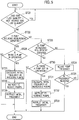
- the control unit 15d determines whether the total flow quantity Q2 of heat source water flowing in the load system side B is equal to the total flow quantity Q1 of heat source water flowing in the heat source side A (ST21). If the total flow quantity Q2 of heat source water flowing in the load system side B is equal to the total flow quantity Q1 of heat source water flowing in the heat source side A (YES in ST21), the control unit 15d determines that no heat source water flows in the bypass pipe 14 and the heat sources 1 of the secondary pump-type heat source system S are efficiently operating. Accordingly, the heat source controller 15 controls the secondary pumps 2 so as to keep the state.
- the control unit 15d determines whether the requirement for reducing the number of secondary pumps 2 in operation is satisfied (ST22). If the control unit 15d determines that the requirement for reducing the number of secondary pumps 2 in operation (hereinafter, referred to as a pump reducing requirement) is not satisfied (NO in ST22), the control unit 15d then determines whether the requirement for increasing the number of secondary pumps 2 in operation is satisfied (ST23).
- control unit 15c determines that the requirement for increasing the number of secondary pumps 2 in operation (hereinafter, referred to as a pump increasing requirement) is not satisfied (NO in ST23), the operating frequency of the secondary pumps 2, or the output frequency of the secondary pump inverters 3 is adjusted (ST24).
- the total flow quantity of heat source water flowing in the heat source side A can be set equal to the total flow quantity of heat source water flowing in the load system side B only by adjusting the operating frequency of the secondary pumps 2 without increasing or reducing the number of secondary pumps 2 in operation.
- the heat sources 1 can be efficiently and properly operated according to the demands of the load systems 9.
- the number of secondary pumps 2 in operation is reduced or increased assuming that the secondary pumps 2 in operation have a same operating frequency.
- control unit 15d adjusts the frequency of the secondary pumps 2 on a basis of the output frequency of the secondary pump inverters 3 currently used to operate the secondary pumps 2. This frequency adjustment cannot be finished at one time in some cases (NO in ST25) and is repeated until a proper frequency is determined.
- PID control or the like is preferably used.
- control unit 15d confirms that plural secondary pumps 2 are currently in operation (YES in ST26) and then instructs the calculation unit 15c to calculate a frequency (an initial frequency) used to operate the heat sources 1 after the number of secondary pumps 2 in operation is reduced (ST27).
- plural secondary pumps 2 are currently in operation and includes a secondary pump 2 which can be stopped because it is impossible to stop all the secondary pumps 2 in the secondary pump-type heat source system S.
- a secondary pump 2 which can be stopped because it is impossible to stop all the secondary pumps 2 in the secondary pump-type heat source system S.
- the heat source water will not flow in the load system side B and the operating condition in the load system side B cannot be known. This prevents the heat source units from appropriately operating so as to respond to changes in the load system side B.
- the number of secondary pumps 2 currently in operation is less than a predetermined number, for example, two (NO in ST26), the number of secondary pumps 2 in operation cannot be reduced, and the operation is continued without changes.
- examples of the pump reducing requirement include the following requirements: there is a heat source unit in which the secondary pump 2 is in operation while the heat source 1 is stopped with the compressor in the heat source 1 out of operation; and the frequency instructed to the secondary pump 2 reaches the minimum frequency at which the secondary pumps 2 can operate to reduce the flow quantity per heat source 1 to the minimum flow quantity of the heat source 1.
- the secondary pump 2 when there is a heat source unit in which the secondary pump 2 is in operation but the heat source 1 is stopped, the secondary pump 2 is operating just to maintain the flow quantity, and stopping the secondary pump 2 will not cause a problem.
- the flow quantity can be reduced by reducing the frequency of the secondary pumps 2 at ST24 if the frequency instructed to the secondary pumps 2 does not reach the minimum frequency at which the secondary pump 2 can operate to minimize the flow quantity per heat source 1.
- the number of secondary pumps 2 in operation is reduced when the following requirements are satisfied in which: plural secondary pumps 2 are in operation when it is judged whether the aforementioned pump reducing requirements are satisfied and the two pump reducing requirements are both satisfied.
- These pump reducing requirements are just examples and can be arbitrarily set according to the state of the secondary pumps installed in the secondary pump-type heat source system S and the like.
- the calculation unit 15c calculates a frequency (an initial frequency) used to operate the heat sources 1 after the number of secondary pumps 2 in operation is reduced. This initial frequency is calculated according to the following procedure.
- the total flow quantity Q1 of heat source water flowing in the heat source side A is divided by the number of secondary pumps in operation at this calculation.
- the flow quantity per secondary pump 2 in operation (average flow quantity q0) is thus calculated.
- a lifting height h0 of the heat source 1 is calculated.
- FIG. 6 is a graph showing a relation among three of the average flow quantity q0, operating frequency f0, and lifting height h0 for calculating the lifting height h0 based on the average flow quantity q0 and operating frequency f0.
- the graph of FIG. 6 shows the lifting height in the vertical axis and the flow quantity in the horizontal axis.
- the storage unit 15b may store the approximate equation drawing the graph or a table of discrete values. As shown in FIG. 6 , if the average flow quantity q0 and operating frequency f0 are known, the lifting height h0 of the heat source 1 can be calculated.
- calculation of the initial frequency uses the lifting height for the following reasons.
- plural secondary pumps 2 installed in the heat source side A operate at a same frequency. This is because if the secondary pumps 2 operate at different frequencies, the performances thereof differ from one another, and the control thereof is very difficult. This makes it difficult to perform smooth operation control, thus resulting in low efficiency operation.
- the heat sources 1 operate using the same operating frequency as the previous one after the number of heat sources 1 is increased or reduced, it is prevented that heat source water is supplied so as to accurately respond to changes in the load system side B.
- the lifting height of the secondary pumps 2 at the calculation of the initial frequency are once calculated, and the frequency, which allows the same lifting height to be maintained after the number of secondary pumps 2 in operation is increased or reduced, is then calculated.
- the lifting height h0 of each heat source 1 can be calculated based on the point indicated by the operating frequency f0 and the average flow quantity q0.
- the flow quantity of heat source water flowing in each secondary pump 2 is calculated.
- the number of secondary pumps 2 operated using the initial frequency is set to a number obtained by subtracting one from the number of secondary pumps 2 previously in operation.
- the total flow quantity Q1 of heat source water flowing in the heat source side A is divided by the number obtained by subtracting one from the number of secondary pumps 2 previously in operation to obtain the flow quantity q1 per secondary pump 2 in operation at the initial frequency.
- the aforementioned procedure provides the lifting height h0 and the flow quantity q1 of heat source water per secondary pump 2 after the number of secondary pumps 2 in operation is reduced.
- the frequency passing through the point indicated by the lifting height h0 and flow quantity q1 is calculated using the graph shown in FIG. 7 . This frequency corresponds to the initial frequency f1.
- the control unit 15d determines a secondary pump 2 to be stopped and instructs the instruction creation unit 15e to send a pump reduction instruction to the corresponding heat source unit. Based on the instruction, the instruction creation unit 15e sends the pump reduction instruction to the corresponding heat source unit through the transmission unit 15f (ST28).
- the initial frequency f1 calculated by the calculation unit 15c is transmitted to the inverters 3 of the secondary pumps 2 through the control unit 15d, instruction creation unit 15e, and transmission unit 15f (ST29).
- the secondary pumps 2 are operated at the transmitted initial frequency f1.
- the control unit 15d confirms that the secondary pumps 2 include a secondary pump 2 not in operation (YES in ST30). The control unit 15d then instructs the calculation unit 15c to calculate a frequency (an initial frequency) used to operate the heat sources 1 after the number of secondary pumps 2 is increased (ST31). If all of the secondary pumps 2 are in operation, the current operation is continued without any changes (NO in ST30).
- Examples of the pump increasing requirements include the following requirements: the operating performances of all of the heat sources 1 with the secondary pumps 2 in operation exceed the maximum efficiency points and the flow quantity of heat source water per heat source 1 will not be below the minimum flow quantity if the number of secondary pumps 2 is increased; and the frequency instructed to the secondary pumps 2 reaches the maximum frequency with which the secondary pumps 2 can operate to increase the flow quantity per heat source 1 to the maximum flow quantity of the heat source 1.
- the number of secondary pumps 2 in operation is increased when the requirement that at least one of the secondary pumps 2 is not in operation at the determination whether the pump increasing requirements are satisfied and any one of the aforementioned two pump increasing requirements is satisfied.
- the pump increasing requirements are just examples and can be arbitrarily set according to the state of the secondary pumps installed in the secondary pump-type heat source system S.
- the calculation unit 15c calculates a frequency (an initial frequency) used to operate the secondary pumps 2 after the number of secondary pumps 2 in operation is increased.
- the way of calculating the initial frequency is the same as the aforementioned way for the pump reducing requirements.
- the total flow quantity Q1 of heat source water flowing in the heat source side A is divided by the number of secondary pumps 2 in operation at the calculation.
- the flow quantity per secondary pumps 2 in operation (average flow quantity q0) is calculated.
- the lifting height h0 of the heat source 1 is calculated.
- the flow quantity q1 of heat source water flowing in each secondary pump 2 is calculated in the case where the number of secondary pumps 2 in operation is increased.
- the total flow quantity Q1 of heat source water flowing in the heat source side A is divided by a number obtained by adding one to the number of secondary pumps 2 previously in operation to obtain the flow quantity q1 per secondary pump 2 operated using the initial frequency.
- the initial frequency f1 used to operate the secondary pumps 2 is calculated in the case where the number of secondary pumps 2 in operation is increased.
- the control unit 15d determines the heat source unit to be started and instructs the instruction creation unit 15e to send the pump increasing instruction to the heat source unit. Based on the instruction, the instruction creation unit 15e sends the pump increasing instruction to the heat source unit through the transmission unit 15f (ST32).
- the initial frequency f1 calculated by the calculation unit 15c is transmitted to the inverters 3 of the secondary pumps 2 through the control unit 15d, instruction creation unit 15e, and transmission unit 15f (ST33).
- the secondary pumps 2 are operated at the transmitted initial frequency f1.
- the flow quantity s of heat source water flowing in the heat source side and the load system side can be calculated by using only temperature sensors instead of flow meters. Accordingly, the entire system can be constructed at low cost. Moreover, it is possible to control the heat sources while always accurately responding to changes in the load system side by using the calculated flow quantities of heat source water flowing in the heat source side and load system side. It is therefore possible to efficiently operate the heat sources while contributing the energy saving.
- the present invention is not limited to the aforementioned embodiment and can be embodied by modifying the constituent components without departing from the scope thereof.
- the plurality of constituent components disclosed in the above embodiment are properly combined to form various kinds of the invention. For example, some of all the constituent components shown in the embodiment may be deleted. Furthermore, some of the constituent components of different embodiments are properly combined.
- the embodiment of the present invention is described.
- the above description just exemplifies the specific example and does not limit the present invention.
- the specific configuration of each part and the like can be properly changed.
- the operations and effects described in the embodiment are just the most preferable ones provided by the invention, and the operations and effects of the present invention are not limited by the description of the embodiment of the present invention.
- the present invention is used in a place requiring air conditioning of plural air conditioning areas such as a large-scale factory or building, for example.
Landscapes
- Engineering & Computer Science (AREA)
- Mechanical Engineering (AREA)
- General Engineering & Computer Science (AREA)
- Chemical & Material Sciences (AREA)
- Combustion & Propulsion (AREA)
- Physics & Mathematics (AREA)
- Thermal Sciences (AREA)
- Air Conditioning Control Device (AREA)
- Other Air-Conditioning Systems (AREA)
Claims (3)
- Sekundärpumpen-Wärmequellensystem, das Folgendes umfasst:eine Vielzahl von Wärmequellen (1a, 1b, 1c), die parallel verbunden sind und Wärmequellenwasser erzeugen,ein Lastsystem (9), in dem das Wärmequellenwasser fließt,eine Primärpumpe (7), die das Wärmequellenwasser dem Lastsystem (9) zuführt,ein Wasserzufuhrrohr (6), das einen Auslass jeder Wärmequelle und das Lastsystem (9) verbindet,eine Sekundärpumpe (2a, 2b, 2c), die für jede Wärmequelle (1a, 1b, 1c) bereitgestellt wird und das Wärmequellenwasser, das in dem Lastsystem (9) einem Wärmeaustausch unterworfen ist, jeder Wärmequelle (1a, 1b, 1c) zuführt,ein Wasserrückflussrohr (11), das einen Auslass des Lastsystems und die Sekundärpumpen (2a, 2b, 2c) verbindet,ein Umgehungsrohr (14), das ermöglicht, dass das Wasserzufuhrrohr und das Wasserrückflussrohr miteinander in Verbindung stehen, undeinen Wassertemperatursensor, der eine Temperatur des Wärmequellenwassers erfasst,dadurch gekennzeichnet, dass das Sekundärpumpen-Wärmequellensystem ferner Folgendes umfasst:eine Wärmequellensteuerung (15), die eine Durchflussmenge des Wärmequellenwassers, das in jeder Wärmequellenseite fließt, und eine Durchflussmenge des Wärmequellenwassers, das in der Lastsystemseite fließt, durch Zuweisen eines Ergebnisses von einer Messung durch den Wassertemperatursensor zu einem Betriebsmerkmal jeder der Wärmequellen (1a, 1b, 1c) berechnet und den Betrieb der Sekundärpumpen (2a, 2b, 2c) auf Grundlage des Ergebnisses von der Berechnung steuert,wobei der Wassertemperatursensor Folgendes umfasst:einen Zufuhr-Wassertemperatursensor (12), der eine Temperatur des Wärmequellenwassers misst, das durch das Wasserzufuhrrohr (6) zwischen jeder Wärmequelle (1a, 1b, 1c) und dem Lastsystem (9) fließt,einen Rückfluss-Wassertemperatursensor (13), der eine Temperatur des Wärmequellenwassers misst, das durch das Wasserrückflussrohr (11) zwischen dem Lastsystem (9) und den Sekundärpumpen (2a, 2b, 2c) fließt,einen Wärmequelleneinlass-Wassertemperatursensor (4a, 4b, 4c), der eine Temperatur des Wärmequellenwassers misst, das der Wärmequelle (1a, 1b, 1c) zugeführt wird, an einem Einlass jeder Wärmequelle undeinen Wärmequellenauslass-Wassertemperatursensor (5a, 5b, 5c), der eine Temperatur des Wärmequellenwassers misst, das dem Lastsystem (9) von jeder Wärmequelle (1a, 1b, 1c) zugeführt wird, an dem Auslass jeder Wärmequelle undwobei die Wärmequellensteuerung (15) Folgendes umfasst:eine Speichereinheit (15b), die ein Betriebsmerkmal jeder zu steuernden Wärmequelle (1a, 1b, 1c) speichert,eine Berechnungseinheit (15c), die Ergebnisse einer Messung durch den Zufuhr- und den Rückfluss-Wassertemperatursensor (12, 13) und den Wärmequelleneinlass- und den -auslass-Wassertemperatursensor (4a, 4b, 4c, 5a, 5b, 5c) den in der Speichereinheit (15b) gespeicherten Betriebsmerkmalen zuweist, um die Durchflussmengen des Wärmequellenwassers zu berechnen, das in jeder Wärmequellenseite und der Lastsystemseite fließt, undeine Steuereinheit (15d), die den Betrieb der Sekundärpumpen (2a, 2b, 2c) auf Grundlage eines durch die Berechnungseinheit (15c) berechneten Ergebnisses steuert.
- Verfahren zum Steuern einer Sekundärpumpen-Wärmequelle, die Folgendes einschließt:eine Vielzahl von Wärmequellen (1a, 1b, 1c), die parallel verbunden sind und Wärmequellenwasser erzeugen,ein Lastsystem (9), in dem das Wärmequellenwasser fließt,eine Primärpumpe (7), die das Wärmequellenwasser dem Lastsystem (9) zuführt,ein Wasserzufuhrrohr (6), das einen Auslass jeder Wärmequelle und das Lastsystem (9) verbindet,eine Sekundärpumpe (2a, 2b, 2c), die für jede Wärmequelle (1a, 1b, 1c) bereitgestellt wird und das Wärmequellenwasser, das in dem Lastsystem (9) einem Wärmeaustausch unterworfen ist, jeder Wärmequelle (1a, 1b, 1c) zuführt,ein Wasserrückflussrohr (11), das einen Auslass des Lastsystems und die Sekundärpumpen (2a, 2b, 2c) verbindet,ein Umgehungsrohr (14), das ermöglicht, dass das Wasserzufuhrrohr (6) und das Wasserrückflussrohr (11) miteinander in Verbindung stehen, wobei das Verfahren Folgendes umfasst:Berechnen einer Durchflussmenge des Wärmequellenwassers, das in der Wärmequellenseite fließt, und einer Durchflussmenge des Wärmequellenwassers, das in der Lastsystemseite fließt, auf Grundlage einer Temperatur des Wärmequellenwassers undBestimmen, ob die Anzahl von Sekundärpumpen (2a, 2b, 2c) in Betrieb zu vermindern oder zu steigern ist, um eine Differenz zwischen der Durchflussmenge in der Wärmequellenseite und der Durchflussmenge in der Lastsystemseite zu verringern, auf Grundlage berechneter Durchflussmengen in der Wärmequellenseite und der Lastsystemseite, und Steuern des Betriebs der Sekundärpumpen (2a, 2b, 2c),wobei
das Berechnen der Durchflussmenge des Wärmequellenwassers, das in der Wärmequellenseite fließt, Folgendes umfasst:Berechnen einer Leistung jeder Wärmequelle (1a, 1b, 1c),Berechnen der Durchflussmenge jeder Wärmequelle (1a, 1b, 1c) auf Grundlage der berechneten einzelnen Leistung der Wärmequelle (1a, 1b, 1c) und von Ergebnissen, erhalten von einem Wärmequelleneinlass-Wassertemperatursensor (4a, 4b, 4c), der, an einem Einlass der Wärmequelle, eine Einlass-Wassertemperatur des Wärmequellenwassers misst, das der Wärmequelle (1a, 1b, 1c) zugeführt wird, und einem Wärmequellenauslass-Wassertemperatursensor (5a, 5b, 5c), der, an dem Auslass der Wärmequelle, eine Auslass-Wassertemperatur des Wärmequellenwassers misst, das von der Wärmequelle (1a, 1b, 1c) dem Lastsystem (9) zugeführt wird,Aufsummieren der berechneten Durchflussmengen der Wärmequellen (1a, 1b, 1c), um eine Gesamtdurchflussmenge des Wärmequellenwassers, das in der Wärmequellenseite fließt, zu berechnen,Mitteln von Wassertemperaturen, erhalten durch alle Wärmequelleneinlass-Wassertemperatursensoren (4a, 4b, 4c), und Mitteln von Wassertemperaturen, erhalten durch alle Wärmequellenauslass-Wassertemperatursensoren (5a, 5b, 5c), undVergleichen eines Mittels der Auslass-Wassertemperaturen der Wärmequellen (1a, 1b, 1c) mit einer Zufuhr-Wassertemperatur, gemessen durch einen Zufuhr-Wassertemperatursensor (12), der eine Temperatur des Wärmequellenwassers misst, das in dem Wasserzufuhrrohr (6) zwischen den Wärmequellen (1a, 1b, 1c) und der Primärpumpe (7) fließt,in einem Fall, in dem das Mittel der Auslass-Wassertemperaturen der Wärmequellen (1a, 1b, 1c) gleich der Zufuhr-Wassertemperatur ist, Berechnen einer Durchflussmenge des Wärmequellenwassers, das in der Lastsystemseite fließt, durch Verwenden der Gesamtdurchflussmenge des Wärmequellenwassers, das in der Wärmequellenseite fließt, eines Mittels der Einlass-Wassertemperaturen der Wärmequellen (1a, 1b, 1c), des Mittels der Auslass-Wassertemperaturen der Wärmequellen und einer Rückfluss-Wassertemperatur, gemessen durch einen Rückfluss-Wassertemperatursensor (13) der eine Temperatur des Wärmequellenwassers misst, das durch das Wasserrückflussrohr (11) zwischen dem Lastsystem (8) und den Sekundärpumpen (2a, 2b, 2c) fließt, undin einem Fall, in dem das Mittel der Auslass-Wassertemperaturen der Wärmequellen (1a, 1b, 1c) niedriger ist als die Zufuhr-Wassertemperatur, Berechnen einer Durchflussmenge des Wärmequellenwassers, das in der Lastsystemseite fließt, durch Verwenden der Gesamtdurchflussmenge des Wärmequellenwassers, das in der Wärmequellenseite fließt, des Mittels der Einlass-Wassertemperaturen der Wärmequellen, des Mittels der Auslass-Wassertemperaturen der Wärmequellen und der Rückfluss-Wassertemperatur. - Verfahren zum Steuern der Sekundärpumpen-Wärmequelle nach Anspruch 2 wobei
das Steuern der Sekundärpumpen (2a, 2b, 2c), bei dem eine Wärmequellensteuerung (15) Leistungen ändert, um das Wärmequellenwasser auf Grundlage einer Frequenz zuzuführen, Folgendes umfasst:Feststellen, ob die Durchflussmenge des Wärmequellenwassers, das in jeder Wärmequellenseite fließt, gleich der Durchflussmenge des Wärmequellenwassers, das in der Lastsystemseite fließt, ist,falls die Durchflussmenge jedes Wärmequellenwassers, das in der Wärmequellenseite fließt, nicht gleich der Durchflussmenge des Wärmequellenwassers, das in der Lastsystemseite fließt, ist, Feststellen, ob eine Voraussetzung zum Verringern der Anzahl von Sekundärpumpen (2a, 2b, 2c) in Betrieb erfüllt ist,falls die Voraussetzung zum Verringern der Anzahl von Sekundärpumpen (2a, 2b, 2c) in Betrieb erfüllt ist, Berechnen einer Frequenz, um die verbleibenden Sekundärpumpen (2a, 2b, 2c) beim Verringern der Anzahl von Sekundärpumpen (2a, 2b, 2c) zu betreiben,Antreiben der Sekundärpumpen (2a, 2b, 2c) unter Verwendung der beim Verringern der Anzahl von Sekundärpumpen (2a, 2b, 2c) berechneten Frequenz,falls die Voraussetzung zum Verringern der Anzahl von Sekundärpumpen (2a, 2b, 2c) nicht erfüllt ist, Feststellen, ob eine Voraussetzung zum Steigern der Anzahl von Sekundärpumpen (2a, 2b, 2c) in Betrieb erfüllt ist,falls die Voraussetzung zum Vergrößern der Anzahl von Sekundärpumpen (2a, 2b, 2c) erfüllt ist, Bestätigen der Sekundärpumpe (2a, 2b, 2c) außer Betrieb und Berechnen einer Frequenz, um die Sekundärpumpe (2a, 2b, 2c) außer Betrieb beim Steigern der Anzahl von Sekundärpumpen (2a, 2b, 2c) zu betreiben,Antreiben der Sekundärpumpen (2a, 2b, 2c) unter Verwendung der berechneten Frequenz beim Steigern der Anzahl von Sekundärpumpen (2a, 2b, 2c) undfalls die Voraussetzungen zum Steigern und Verringern der Anzahl von Sekundärpumpen (2a, 2b, 2c) in Betrieb nicht erfüllt sind, Anpassen der Frequenz, um die Sekundärpumpen (2a, 2b, 2c) anzutreiben.
Applications Claiming Priority (2)
| Application Number | Priority Date | Filing Date | Title |
|---|---|---|---|
| JP2009031116 | 2009-02-13 | ||
| PCT/JP2010/051755 WO2010092916A1 (ja) | 2009-02-13 | 2010-02-08 | 二次ポンプ方式熱源システム及び二次ポンプ方式熱源制御方法 |
Publications (3)
| Publication Number | Publication Date |
|---|---|
| EP2397786A1 EP2397786A1 (de) | 2011-12-21 |
| EP2397786A4 EP2397786A4 (de) | 2017-02-01 |
| EP2397786B1 true EP2397786B1 (de) | 2018-11-21 |
Family
ID=42561758
Family Applications (1)
| Application Number | Title | Priority Date | Filing Date |
|---|---|---|---|
| EP10741193.6A Active EP2397786B1 (de) | 2009-02-13 | 2010-02-08 | Sekundärpumpen-wärmequellensystem und sekundärpumpen-wärmequellensteuerverfahren |
Country Status (10)
| Country | Link |
|---|---|
| US (1) | US8939196B2 (de) |
| EP (1) | EP2397786B1 (de) |
| JP (1) | JP4975168B2 (de) |
| KR (1) | KR101244536B1 (de) |
| CN (1) | CN102308155B (de) |
| BR (1) | BRPI1008786B1 (de) |
| HU (1) | HUE043923T2 (de) |
| RU (1) | RU2490561C2 (de) |
| TR (1) | TR201902393T4 (de) |
| WO (1) | WO2010092916A1 (de) |
Families Citing this family (31)
| Publication number | Priority date | Publication date | Assignee | Title |
|---|---|---|---|---|
| JP5246118B2 (ja) * | 2009-09-18 | 2013-07-24 | 日立電線株式会社 | 冷水循環システム |
| JP5523918B2 (ja) * | 2010-04-26 | 2014-06-18 | 日立アプライアンス株式会社 | 冷凍システム |
| JP2012247122A (ja) * | 2011-05-27 | 2012-12-13 | Mitsubishi Electric Corp | 冷凍サイクル装置 |
| US11536507B2 (en) * | 2011-11-17 | 2022-12-27 | Optimum Energy, Llc | Systems and methods for reducing energy consumption of a chilled water distribution system |
| US9454160B2 (en) | 2012-03-21 | 2016-09-27 | Kabushiki Kaisha Toshiba | Thermal recycling plant system, apparatus for controlling a thermal recycling plant and method of controlling a thermal recycling plant |
| JP5932419B2 (ja) * | 2012-03-21 | 2016-06-08 | 株式会社東芝 | 熱回収プラントシステム、熱回収プラント制御装置および熱回収プラント制御方法 |
| JP6083147B2 (ja) * | 2012-08-07 | 2017-02-22 | ダイキン工業株式会社 | 空調システム |
| JP5447627B1 (ja) * | 2012-09-26 | 2014-03-19 | ダイキン工業株式会社 | 熱源システム制御装置 |
| US9759457B1 (en) * | 2012-10-16 | 2017-09-12 | Amazon Technologies, Inc. | Controls solution for primary-secondary chiller plant |
| US9562708B2 (en) | 2012-12-03 | 2017-02-07 | Waterfurnace International, Inc. | Conduit module coupled with heating or cooling module |
| JP6210219B2 (ja) * | 2014-01-31 | 2017-10-11 | 三菱重工サーマルシステムズ株式会社 | ポンプ台数制御方法、ポンプ台数制御装置、ポンプシステム、熱源システム及びプログラム |
| JP6134856B2 (ja) * | 2014-02-20 | 2017-05-24 | 東芝キヤリア株式会社 | 熱源装置 |
| JP6271316B2 (ja) * | 2014-03-27 | 2018-01-31 | 荏原冷熱システム株式会社 | 熱源装置 |
| WO2015162798A1 (ja) * | 2014-04-25 | 2015-10-29 | 三菱電機株式会社 | ヒートポンプチリングシステム及びその制御方法 |
| EP3156747B1 (de) * | 2014-06-10 | 2019-08-14 | Toshiba Carrier Corporation | Wärmequellenmaschine und wärmequellenvorrichtung |
| US10161639B2 (en) * | 2015-03-10 | 2018-12-25 | Joseph Copeland | Heat transfer apparatus and heat transfer system for masonry heater |
| CN104964398A (zh) * | 2015-07-16 | 2015-10-07 | 珠海格力电器股份有限公司 | 空调系统的流量控制方法及装置 |
| JP6511377B2 (ja) * | 2015-09-29 | 2019-05-15 | 三機工業株式会社 | 熱媒体配管システム又は熱媒体配管システムにおける熱媒体搬送システム |
| CN105865105B (zh) * | 2016-03-30 | 2019-01-15 | 北京百度网讯科技有限公司 | 冷冻水二次泵系统的控制方法和装置 |
| WO2017204287A1 (ja) * | 2016-05-27 | 2017-11-30 | 東芝キヤリア株式会社 | 熱源システム、及び熱源システムの制御方法 |
| RU2659993C1 (ru) * | 2017-08-28 | 2018-07-04 | Общество с ограниченной ответственностью "Научно-технический комплекс "Криогенная техника" | Способ управления системой поддержания температурно-влажностного режима |
| CN108534210B (zh) * | 2018-06-14 | 2023-12-01 | 济南金孚瑞供热工程技术有限公司 | 叠加式蓄能型热泵供热系统的实施方法 |
| EP4148343A4 (de) * | 2018-07-09 | 2024-03-06 | Toshiba Carrier Corporation | Wärmequellensystem, wärmequellenmaschine und steuerungsvorrichtung |
| US11592215B2 (en) | 2018-08-29 | 2023-02-28 | Waterfurnace International, Inc. | Integrated demand water heating using a capacity modulated heat pump with desuperheater |
| US20200208927A1 (en) | 2018-12-27 | 2020-07-02 | Trane International Inc. | Fluid control for a variable flow fluid circuit in an hvacr system |
| WO2020183244A2 (en) * | 2019-02-06 | 2020-09-17 | Weston Jeffrey A | Single primary loop, dual secondary loop hydronic hvac system and methods of operation |
| CN111795481B (zh) * | 2019-04-08 | 2023-05-23 | 开利公司 | 空气调节系统及用于其的控制方法 |
| CN111918523B (zh) * | 2020-06-28 | 2023-05-09 | 北京百度网讯科技有限公司 | 制冷系统、制冷系统的控制方法、设备及存储介质 |
| CN111912060A (zh) * | 2020-07-15 | 2020-11-10 | 四川省建筑科学研究院有限公司 | 一种集中空调系统水力平衡自动调适方法及系统 |
| JPWO2023127138A1 (de) * | 2021-12-28 | 2023-07-06 | ||
| CN114877421B (zh) * | 2022-04-21 | 2023-08-29 | 珠海格力机电工程有限公司 | 空调水系统、控制方法及空调机组 |
Family Cites Families (24)
| Publication number | Priority date | Publication date | Assignee | Title |
|---|---|---|---|---|
| US3202208A (en) * | 1962-08-22 | 1965-08-24 | American Hydrotherm Corp | Heat exchange system with automatic pump control |
| US4482006A (en) * | 1980-09-02 | 1984-11-13 | Anderson Cary R | Thermal energy meter |
| SE8006391L (sv) * | 1980-09-12 | 1982-03-13 | Jacob Weitman | Sett att reglera en vermevexlare |
| US4463574A (en) * | 1982-03-15 | 1984-08-07 | Honeywell Inc. | Optimized selection of dissimilar chillers |
| US4483152A (en) * | 1983-07-18 | 1984-11-20 | Butler Manufacturing Company | Multiple chiller control method |
| SU1260644A1 (ru) * | 1984-12-10 | 1986-09-30 | Алтайский научно-исследовательский и проектно-технологический институт животноводства | Устройство дл регулировани расхода воздуха |
| JPS61225534A (ja) * | 1985-03-29 | 1986-10-07 | Tokyo Gas Co Ltd | 冷温水機の運転台数制御方法 |
| JPH05504823A (ja) * | 1988-01-19 | 1993-07-22 | マルチスタツク インターナシヨナル ピーテイーワイ.エルテイーデイー. | 加熱および冷却システムの改良 |
| JP2726478B2 (ja) * | 1989-02-21 | 1998-03-11 | 大阪瓦斯株式会社 | 冷房又は暖房用装置 |
| SU1751610A1 (ru) * | 1990-01-11 | 1992-07-30 | Дальневосточный политехнический институт им.В.В.Куйбышева | Способ вентил ции помещений |
| US5138845A (en) * | 1991-04-09 | 1992-08-18 | Brdg-Tndr Corporation | Method and apparatus for controlling the flow of process fluids |
| JPH05223318A (ja) * | 1991-09-02 | 1993-08-31 | Sanden Corp | 水熱源ヒ−トポンプ式空気調和機の流量表示システム |
| US5946926A (en) * | 1998-04-07 | 1999-09-07 | Hartman; Thomas B. | Variable flow chilled fluid cooling system |
| JP4248099B2 (ja) * | 1999-09-21 | 2009-04-02 | 荏原冷熱システム株式会社 | 冷凍機又は冷温水機の制御方法 |
| WO2004005812A1 (en) * | 2002-07-08 | 2004-01-15 | Danfoss A/S | A method and a device for detecting flash gas |
| JP4173981B2 (ja) * | 2002-09-11 | 2008-10-29 | 株式会社山武 | 2次ポンプ方式熱源変流量制御方法および2次ポンプ方式熱源システム |
| US7028768B2 (en) * | 2003-08-20 | 2006-04-18 | Itt Manufacturing Enterprises, Inc. | Fluid heat exchange control system |
| JP2005337594A (ja) * | 2004-05-27 | 2005-12-08 | Sanki Eng Co Ltd | 空調用熱源システム |
| JP4600139B2 (ja) * | 2004-10-06 | 2010-12-15 | パナソニック株式会社 | 空調装置及びその制御方法 |
| JP2006162101A (ja) * | 2004-12-03 | 2006-06-22 | Hitachi Home & Life Solutions Inc | ヒートポンプ給湯装置 |
| JP4505363B2 (ja) | 2005-03-29 | 2010-07-21 | 東洋熱工業株式会社 | 空調システムの冷温水制御方法 |
| JP4925885B2 (ja) * | 2007-03-26 | 2012-05-09 | 新日本空調株式会社 | 配管系設備における流量測定方法 |
| JP2009030821A (ja) | 2007-07-24 | 2009-02-12 | Yamatake Corp | 送水制御システムおよび送水制御方法 |
| CN201152584Y (zh) * | 2007-12-04 | 2008-11-19 | 广州迪森家用锅炉制造有限公司 | 一种水—水采暖温度调节器和热水器 |
-
2010
- 2010-02-08 EP EP10741193.6A patent/EP2397786B1/de active Active
- 2010-02-08 WO PCT/JP2010/051755 patent/WO2010092916A1/ja not_active Ceased
- 2010-02-08 HU HUE10741193A patent/HUE043923T2/hu unknown
- 2010-02-08 RU RU2011137550/12A patent/RU2490561C2/ru not_active IP Right Cessation
- 2010-02-08 JP JP2010550501A patent/JP4975168B2/ja active Active
- 2010-02-08 KR KR1020117021271A patent/KR101244536B1/ko active Active
- 2010-02-08 US US13/201,192 patent/US8939196B2/en active Active
- 2010-02-08 BR BRPI1008786-9A patent/BRPI1008786B1/pt active IP Right Grant
- 2010-02-08 TR TR2019/02393T patent/TR201902393T4/tr unknown
- 2010-02-08 CN CN201080007680.XA patent/CN102308155B/zh active Active
Non-Patent Citations (1)
| Title |
|---|
| None * |
Also Published As
| Publication number | Publication date |
|---|---|
| EP2397786A1 (de) | 2011-12-21 |
| BRPI1008786A2 (pt) | 2016-03-15 |
| CN102308155A (zh) | 2012-01-04 |
| WO2010092916A1 (ja) | 2010-08-19 |
| TR201902393T4 (tr) | 2019-03-21 |
| KR20110126688A (ko) | 2011-11-23 |
| EP2397786A4 (de) | 2017-02-01 |
| JP4975168B2 (ja) | 2012-07-11 |
| BRPI1008786B1 (pt) | 2020-11-24 |
| US20120055665A1 (en) | 2012-03-08 |
| JPWO2010092916A1 (ja) | 2012-08-16 |
| RU2011137550A (ru) | 2013-03-20 |
| KR101244536B1 (ko) | 2013-03-18 |
| CN102308155B (zh) | 2014-01-08 |
| US8939196B2 (en) | 2015-01-27 |
| RU2490561C2 (ru) | 2013-08-20 |
| HUE043923T2 (hu) | 2019-09-30 |
Similar Documents
| Publication | Publication Date | Title |
|---|---|---|
| EP2397786B1 (de) | Sekundärpumpen-wärmequellensystem und sekundärpumpen-wärmequellensteuerverfahren | |
| US11493246B2 (en) | Demand flow for air cooled chillers | |
| US7890215B2 (en) | Optimized control system for cooling systems | |
| US10203136B2 (en) | Air conditioning system and method for controlling same | |
| JP2022137259A (ja) | 主制御装置での建物の改装により冷却システムの作動効率を改善する方法 | |
| US20130274948A1 (en) | Heat source system and method for controlling the number of operated devices in heat source system | |
| US8701424B2 (en) | Turbo chiller, heat source system, and method for controlling the same | |
| JP5029913B2 (ja) | 空調システム及びその制御方法 | |
| JP6644559B2 (ja) | 熱源制御システム、制御方法および制御装置 | |
| US11143434B2 (en) | Refrigeration cycle apparatus | |
| JP5240134B2 (ja) | 冷水循環システム | |
| JP6198398B2 (ja) | 2ポンプ方式熱源設備におけるポンプ運転台数決定制御方法 | |
| JP5286479B2 (ja) | 冷水循環システム | |
| JP5195696B2 (ja) | 冷水循環システム | |
| JP5314542B2 (ja) | 冷水循環システム | |
| KR20170039114A (ko) | 냉·난방 공조설비에서 반송동력 절감 제어장치 |
Legal Events
| Date | Code | Title | Description |
|---|---|---|---|
| PUAI | Public reference made under article 153(3) epc to a published international application that has entered the european phase |
Free format text: ORIGINAL CODE: 0009012 |
|
| 17P | Request for examination filed |
Effective date: 20110810 |
|
| AK | Designated contracting states |
Kind code of ref document: A1 Designated state(s): AT BE BG CH CY CZ DE DK EE ES FI FR GB GR HR HU IE IS IT LI LT LU LV MC MK MT NL NO PL PT RO SE SI SK SM TR |
|
| DAX | Request for extension of the european patent (deleted) | ||
| RA4 | Supplementary search report drawn up and despatched (corrected) |
Effective date: 20170105 |
|
| RIC1 | Information provided on ipc code assigned before grant |
Ipc: F24F 3/06 20060101ALI20161223BHEP Ipc: F24F 11/00 20060101ALI20161223BHEP Ipc: F25B 49/00 20060101AFI20161223BHEP |
|
| REG | Reference to a national code |
Ref country code: DE Ref legal event code: R079 Ref document number: 602010055267 Country of ref document: DE Free format text: PREVIOUS MAIN CLASS: F24F0011020000 Ipc: F25B0013000000 |
|
| GRAP | Despatch of communication of intention to grant a patent |
Free format text: ORIGINAL CODE: EPIDOSNIGR1 |
|
| STAA | Information on the status of an ep patent application or granted ep patent |
Free format text: STATUS: GRANT OF PATENT IS INTENDED |
|
| RIC1 | Information provided on ipc code assigned before grant |
Ipc: F24F 3/06 20060101ALI20180517BHEP Ipc: F25B 25/00 20060101ALI20180517BHEP Ipc: F25B 13/00 20060101AFI20180517BHEP Ipc: F24F 11/83 20180101ALI20180517BHEP Ipc: F24F 140/20 20180101ALI20180517BHEP |
|
| INTG | Intention to grant announced |
Effective date: 20180620 |
|
| GRAS | Grant fee paid |
Free format text: ORIGINAL CODE: EPIDOSNIGR3 |
|
| GRAA | (expected) grant |
Free format text: ORIGINAL CODE: 0009210 |
|
| STAA | Information on the status of an ep patent application or granted ep patent |
Free format text: STATUS: THE PATENT HAS BEEN GRANTED |
|
| AK | Designated contracting states |
Kind code of ref document: B1 Designated state(s): AT BE BG CH CY CZ DE DK EE ES FI FR GB GR HR HU IE IS IT LI LT LU LV MC MK MT NL NO PL PT RO SE SI SK SM TR |
|
| REG | Reference to a national code |
Ref country code: CH Ref legal event code: EP |
|
| REG | Reference to a national code |
Ref country code: IE Ref legal event code: FG4D |
|
| REG | Reference to a national code |
Ref country code: AT Ref legal event code: REF Ref document number: 1068007 Country of ref document: AT Kind code of ref document: T Effective date: 20181215 |
|
| REG | Reference to a national code |
Ref country code: DE Ref legal event code: R096 Ref document number: 602010055267 Country of ref document: DE |
|
| REG | Reference to a national code |
Ref country code: NL Ref legal event code: MP Effective date: 20181121 |
|
| REG | Reference to a national code |
Ref country code: AT Ref legal event code: MK05 Ref document number: 1068007 Country of ref document: AT Kind code of ref document: T Effective date: 20181121 |
|
| REG | Reference to a national code |
Ref country code: GR Ref legal event code: EP Ref document number: 20190400298 Country of ref document: GR Effective date: 20190422 |
|
| PG25 | Lapsed in a contracting state [announced via postgrant information from national office to epo] |
Ref country code: AT Free format text: LAPSE BECAUSE OF FAILURE TO SUBMIT A TRANSLATION OF THE DESCRIPTION OR TO PAY THE FEE WITHIN THE PRESCRIBED TIME-LIMIT Effective date: 20181121 Ref country code: NO Free format text: LAPSE BECAUSE OF FAILURE TO SUBMIT A TRANSLATION OF THE DESCRIPTION OR TO PAY THE FEE WITHIN THE PRESCRIBED TIME-LIMIT Effective date: 20190221 Ref country code: LT Free format text: LAPSE BECAUSE OF FAILURE TO SUBMIT A TRANSLATION OF THE DESCRIPTION OR TO PAY THE FEE WITHIN THE PRESCRIBED TIME-LIMIT Effective date: 20181121 Ref country code: FI Free format text: LAPSE BECAUSE OF FAILURE TO SUBMIT A TRANSLATION OF THE DESCRIPTION OR TO PAY THE FEE WITHIN THE PRESCRIBED TIME-LIMIT Effective date: 20181121 Ref country code: IS Free format text: LAPSE BECAUSE OF FAILURE TO SUBMIT A TRANSLATION OF THE DESCRIPTION OR TO PAY THE FEE WITHIN THE PRESCRIBED TIME-LIMIT Effective date: 20190321 Ref country code: ES Free format text: LAPSE BECAUSE OF FAILURE TO SUBMIT A TRANSLATION OF THE DESCRIPTION OR TO PAY THE FEE WITHIN THE PRESCRIBED TIME-LIMIT Effective date: 20181121 Ref country code: LV Free format text: LAPSE BECAUSE OF FAILURE TO SUBMIT A TRANSLATION OF THE DESCRIPTION OR TO PAY THE FEE WITHIN THE PRESCRIBED TIME-LIMIT Effective date: 20181121 Ref country code: BG Free format text: LAPSE BECAUSE OF FAILURE TO SUBMIT A TRANSLATION OF THE DESCRIPTION OR TO PAY THE FEE WITHIN THE PRESCRIBED TIME-LIMIT Effective date: 20190221 Ref country code: HR Free format text: LAPSE BECAUSE OF FAILURE TO SUBMIT A TRANSLATION OF THE DESCRIPTION OR TO PAY THE FEE WITHIN THE PRESCRIBED TIME-LIMIT Effective date: 20181121 |
|
| PG25 | Lapsed in a contracting state [announced via postgrant information from national office to epo] |
Ref country code: NL Free format text: LAPSE BECAUSE OF FAILURE TO SUBMIT A TRANSLATION OF THE DESCRIPTION OR TO PAY THE FEE WITHIN THE PRESCRIBED TIME-LIMIT Effective date: 20181121 Ref country code: SE Free format text: LAPSE BECAUSE OF FAILURE TO SUBMIT A TRANSLATION OF THE DESCRIPTION OR TO PAY THE FEE WITHIN THE PRESCRIBED TIME-LIMIT Effective date: 20181121 Ref country code: PT Free format text: LAPSE BECAUSE OF FAILURE TO SUBMIT A TRANSLATION OF THE DESCRIPTION OR TO PAY THE FEE WITHIN THE PRESCRIBED TIME-LIMIT Effective date: 20190321 |
|
| PG25 | Lapsed in a contracting state [announced via postgrant information from national office to epo] |
Ref country code: CZ Free format text: LAPSE BECAUSE OF FAILURE TO SUBMIT A TRANSLATION OF THE DESCRIPTION OR TO PAY THE FEE WITHIN THE PRESCRIBED TIME-LIMIT Effective date: 20181121 Ref country code: PL Free format text: LAPSE BECAUSE OF FAILURE TO SUBMIT A TRANSLATION OF THE DESCRIPTION OR TO PAY THE FEE WITHIN THE PRESCRIBED TIME-LIMIT Effective date: 20181121 Ref country code: DK Free format text: LAPSE BECAUSE OF FAILURE TO SUBMIT A TRANSLATION OF THE DESCRIPTION OR TO PAY THE FEE WITHIN THE PRESCRIBED TIME-LIMIT Effective date: 20181121 |
|
| REG | Reference to a national code |
Ref country code: DE Ref legal event code: R097 Ref document number: 602010055267 Country of ref document: DE |
|
| PG25 | Lapsed in a contracting state [announced via postgrant information from national office to epo] |
Ref country code: RO Free format text: LAPSE BECAUSE OF FAILURE TO SUBMIT A TRANSLATION OF THE DESCRIPTION OR TO PAY THE FEE WITHIN THE PRESCRIBED TIME-LIMIT Effective date: 20181121 Ref country code: EE Free format text: LAPSE BECAUSE OF FAILURE TO SUBMIT A TRANSLATION OF THE DESCRIPTION OR TO PAY THE FEE WITHIN THE PRESCRIBED TIME-LIMIT Effective date: 20181121 Ref country code: SM Free format text: LAPSE BECAUSE OF FAILURE TO SUBMIT A TRANSLATION OF THE DESCRIPTION OR TO PAY THE FEE WITHIN THE PRESCRIBED TIME-LIMIT Effective date: 20181121 Ref country code: SK Free format text: LAPSE BECAUSE OF FAILURE TO SUBMIT A TRANSLATION OF THE DESCRIPTION OR TO PAY THE FEE WITHIN THE PRESCRIBED TIME-LIMIT Effective date: 20181121 |
|
| REG | Reference to a national code |
Ref country code: DE Ref legal event code: R119 Ref document number: 602010055267 Country of ref document: DE |
|
| PLBE | No opposition filed within time limit |
Free format text: ORIGINAL CODE: 0009261 |
|
| STAA | Information on the status of an ep patent application or granted ep patent |
Free format text: STATUS: NO OPPOSITION FILED WITHIN TIME LIMIT |
|
| REG | Reference to a national code |
Ref country code: HU Ref legal event code: AG4A Ref document number: E043923 Country of ref document: HU Ref country code: CH Ref legal event code: PL |
|
| 26N | No opposition filed |
Effective date: 20190822 |
|
| PG25 | Lapsed in a contracting state [announced via postgrant information from national office to epo] |
Ref country code: MC Free format text: LAPSE BECAUSE OF FAILURE TO SUBMIT A TRANSLATION OF THE DESCRIPTION OR TO PAY THE FEE WITHIN THE PRESCRIBED TIME-LIMIT Effective date: 20181121 Ref country code: LU Free format text: LAPSE BECAUSE OF NON-PAYMENT OF DUE FEES Effective date: 20190208 Ref country code: SI Free format text: LAPSE BECAUSE OF FAILURE TO SUBMIT A TRANSLATION OF THE DESCRIPTION OR TO PAY THE FEE WITHIN THE PRESCRIBED TIME-LIMIT Effective date: 20181121 |
|
| REG | Reference to a national code |
Ref country code: BE Ref legal event code: MM Effective date: 20190228 |
|
| REG | Reference to a national code |
Ref country code: IE Ref legal event code: MM4A |
|
| PG25 | Lapsed in a contracting state [announced via postgrant information from national office to epo] |
Ref country code: LI Free format text: LAPSE BECAUSE OF NON-PAYMENT OF DUE FEES Effective date: 20190228 Ref country code: CH Free format text: LAPSE BECAUSE OF NON-PAYMENT OF DUE FEES Effective date: 20190228 |
|
| PG25 | Lapsed in a contracting state [announced via postgrant information from national office to epo] |
Ref country code: IE Free format text: LAPSE BECAUSE OF NON-PAYMENT OF DUE FEES Effective date: 20190208 Ref country code: DE Free format text: LAPSE BECAUSE OF NON-PAYMENT OF DUE FEES Effective date: 20190903 |
|
| PG25 | Lapsed in a contracting state [announced via postgrant information from national office to epo] |
Ref country code: BE Free format text: LAPSE BECAUSE OF NON-PAYMENT OF DUE FEES Effective date: 20190228 |
|
| PG25 | Lapsed in a contracting state [announced via postgrant information from national office to epo] |
Ref country code: MT Free format text: LAPSE BECAUSE OF NON-PAYMENT OF DUE FEES Effective date: 20190208 |
|
| PG25 | Lapsed in a contracting state [announced via postgrant information from national office to epo] |
Ref country code: CY Free format text: LAPSE BECAUSE OF FAILURE TO SUBMIT A TRANSLATION OF THE DESCRIPTION OR TO PAY THE FEE WITHIN THE PRESCRIBED TIME-LIMIT Effective date: 20181121 |
|
| PG25 | Lapsed in a contracting state [announced via postgrant information from national office to epo] |
Ref country code: MK Free format text: LAPSE BECAUSE OF FAILURE TO SUBMIT A TRANSLATION OF THE DESCRIPTION OR TO PAY THE FEE WITHIN THE PRESCRIBED TIME-LIMIT Effective date: 20181121 |
|
| PGFP | Annual fee paid to national office [announced via postgrant information from national office to epo] |
Ref country code: GB Payment date: 20241219 Year of fee payment: 16 |
|
| PGFP | Annual fee paid to national office [announced via postgrant information from national office to epo] |
Ref country code: FR Payment date: 20241209 Year of fee payment: 16 |
|
| PGFP | Annual fee paid to national office [announced via postgrant information from national office to epo] |
Ref country code: HU Payment date: 20250113 Year of fee payment: 16 |
|
| PGFP | Annual fee paid to national office [announced via postgrant information from national office to epo] |
Ref country code: GR Payment date: 20250116 Year of fee payment: 16 |
|
| PGFP | Annual fee paid to national office [announced via postgrant information from national office to epo] |
Ref country code: IT Payment date: 20250110 Year of fee payment: 16 |
|
| PGFP | Annual fee paid to national office [announced via postgrant information from national office to epo] |
Ref country code: TR Payment date: 20250128 Year of fee payment: 16 |