EP2397739B1 - Kupplung für Faltenrohr - Google Patents
Kupplung für Faltenrohr Download PDFInfo
- Publication number
- EP2397739B1 EP2397739B1 EP11171164A EP11171164A EP2397739B1 EP 2397739 B1 EP2397739 B1 EP 2397739B1 EP 11171164 A EP11171164 A EP 11171164A EP 11171164 A EP11171164 A EP 11171164A EP 2397739 B1 EP2397739 B1 EP 2397739B1
- Authority
- EP
- European Patent Office
- Prior art keywords
- main body
- coupling according
- ring
- previous
- coupling
- Prior art date
- Legal status (The legal status is an assumption and is not a legal conclusion. Google has not performed a legal analysis and makes no representation as to the accuracy of the status listed.)
- Active
Links
Images
Classifications
-
- F—MECHANICAL ENGINEERING; LIGHTING; HEATING; WEAPONS; BLASTING
- F16—ENGINEERING ELEMENTS AND UNITS; GENERAL MEASURES FOR PRODUCING AND MAINTAINING EFFECTIVE FUNCTIONING OF MACHINES OR INSTALLATIONS; THERMAL INSULATION IN GENERAL
- F16L—PIPES; JOINTS OR FITTINGS FOR PIPES; SUPPORTS FOR PIPES, CABLES OR PROTECTIVE TUBING; MEANS FOR THERMAL INSULATION IN GENERAL
- F16L25/00—Construction or details of pipe joints not provided for in, or of interest apart from, groups F16L13/00 - F16L23/00
- F16L25/0036—Joints for corrugated pipes
-
- F—MECHANICAL ENGINEERING; LIGHTING; HEATING; WEAPONS; BLASTING
- F24—HEATING; RANGES; VENTILATING
- F24S—SOLAR HEAT COLLECTORS; SOLAR HEAT SYSTEMS
- F24S80/00—Details, accessories or component parts of solar heat collectors not provided for in groups F24S10/00-F24S70/00
- F24S80/30—Arrangements for connecting the fluid circuits of solar collectors with each other or with other components, e.g. pipe connections; Fluid distributing means, e.g. headers
-
- F—MECHANICAL ENGINEERING; LIGHTING; HEATING; WEAPONS; BLASTING
- F28—HEAT EXCHANGE IN GENERAL
- F28F—DETAILS OF HEAT-EXCHANGE AND HEAT-TRANSFER APPARATUS, OF GENERAL APPLICATION
- F28F9/00—Casings; Header boxes; Auxiliary supports for elements; Auxiliary members within casings
- F28F9/02—Header boxes; End plates
- F28F9/0246—Arrangements for connecting header boxes with flow lines
Definitions
- the present invention relates to a coupling for a corrugated tube, that is to say a coupling for connecting a corrugated tube to a utility device, such as a solar panel or tank.
- EP-1347227A2 discloses a coupling comprising a main body with a support seat an assembly seat, a cut ring and a nut to be serewed onto the main body.
- the purpose of the present invention is to make a coupling for a corrugated tube which is particularly easy and efficient to install.
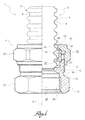
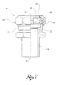
- FIG. 1 shows a partial view in longitudinal cross-section of a coupling according to the present innovation, in an initial assembly configuration
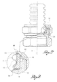
- figure 2 shows the coupling in figure 1 , in a final assembly configuration
- figure 3 shows an enlargement of the detail III in figure 2 ;
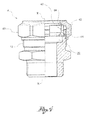
- FIG. 4 shows a view, partially in longitudinal cross-section, of a coupling according to the present invention according to a further embodiment, particularly suitable for screwing to the utility device;
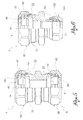
- FIG. 5 shows a view, partially in longitudinal cross-section, of a coupling according to the present invention according to a further embodiment, particularly suitable for connection to corrugated tubes at both ends;
- FIG. 6 shows a view, partially in longitudinal cross-section, of a coupling according to the present invention according to a further embodiment, particularly suitable for connection to a corrugated tube at one end and a copper pipe at the other end;
- FIG. 7 shows a view, partially in longitudinal cross-section, of a coupling according to the present invention, according to a further embodiment, particularly suitable for connection to a corrugated tube at one end and the insertion of the utility device at the other end.
- substantially sharp edged appears recurrently; such expression is understood to mean an edge deriving from machining structured so as not to include bevels or connections, as far as permitted by the technological limitations of such machining, by the tools utilised therein and materials utilised for the component.
- reference numeral 1 globally denotes an assembly comprising a corrugated tube 2 and a coupling 4 for the connection of the corrugated tube to a utility device, such as a solar panel or tank.
- the corrugated tube 2 has, along a longitudinal axis X, a sequence of corrugations which form an alternate succession of peaks 6 and valleys 8.
- the tube 2 terminates, at the end engaging with the coupling 4, in a terminal corrugation, having a terminal crest 6'.
- the corrugated tube is made of metal.
- the coupling 4 hollow on the inside for the transit of the fluid, comprises a main body 10, preferably made in a single piece, for example in brass.
- the main body 10 comprises a threaded outer portion 12, a relief groove 14 and a grip head 16, preferably of a polygonal shape, to permit the gripping of a tool, such as a spanner, for fitting the coupling 4 to the utility device.
- the main body 10 comprises an annular support seat 20, defined on the bottom by a crown-shaped support surface 20', contained on a plane, and an annular assembly seat 22, having a smaller diameter than that of the support seat.
- the support seat 20 is defined circumferentially by a cylindrical surface; in the same way the assembly seat 22 is defined circumferentially by a cylindrical surface.
- the passage from the support seat 20 to the assembly seat 22 is defined circumferentially by a substantially sharp edge (consisting of the inner diameter of the circular crown defining the support surface 20').
- the assembly seat 22 has a circumferentially continuous annular abutment wall 24 on the bottom having a radial extension such as to permit the abutment of the end of the tube and in particular of the terminal corrugation thereof.
- the main body 10 On the other side of the abutment wall 24, the main body 10 has an engagement recess 26 defined by an inner threaded portion 28, for screwing to the utility device.
- the coupling 4 further comprises a ring 40 preferably made in a single piece, having a longitudinal slit through its thickness and from one end of the other, which confers structural stability.
- Such structural flexibility permits a deformation of the ring which, in a non-deformed configuration, such as that shown in figure 1 , has a larger inner or outer diameter than in a deformed configuration, such as that shown in figure 2 .
- the ring 40 comprises a main annular wall 42, having a substantially constant inner and outer diameter, and an annular support foot 44.
- the support foot 44 is preferably cylindrical on the outside, ending with a substantially sharp edge and flush with the main wall 42; preferably, moreover, said foot 44 is internally at least partially tapered, converging towards the support wall 20 of the main body 10.
- the coupling 4 further comprises a nut 60, which can be screwed onto the inner portion 12 of the main body 10 and fitted internally with an active wall 62 to use for assembly to the ring 40.
- the active wall 62 has a tapered contact surface 64, divergent towards the main body 10.
- the active wall 62 comprises an annular shoulder 66 of a cylindrical shape in correspondence with the minimum diameter of the contact surface 64, having an inner diameter even smaller than the minimum diameter of the contact surface.
- the nut 60 is outwardly shaped in a polygonal manner, so as to be gripped by an assembly tool.
- the ring 40 In an initial assembly configuration of the tube 2 to the coupling 4 ( figure 1 ), the ring 40 is in the non-deformed configuration and rests against the support surface 20'; in particular the foot 44 of the ring 40 abuts against said support surface 20'.
- the nut 60 is partially screwed to the main body 10, so that the ring 40 and in particular the main wall 42 thereof, abuts against the active wall 62 of the nut 60, and in particular against the tapered contact surface 64.
- the tube 2 is inserted in the coupling 4 and the end of it abuts with the abutment wall 24 of the main body 10.
- the terminal corrugation of the tube which abuts with the abutment wall 24, is positioned between the foot 44 of the ring 40 and said abutment wall.
- the minimum inner diameter of the foot 44 of the ring 40 is less than the maximum diameter of the terminal crest 6', so that the tube 2 is snap inserted in the coupling.
- the at least partially tapered shape of the foot 44 of the ring 40 facilitates the insertion of the terminal crest 6' of the tube and its snap engagement.
- the snap insertion of the corrugated tube in the ring defines the position of the end of the tube in relation to the ring and consequently in relation to the coupling body during assembly, without further intervention by the operator performing assembly.
- the coupling passes from the initial configuration to the final assembly configuration ( figure 2 ).
- the active wall 62 of the nut 60 influences the ring 40 so as to compress it and reduce its radial dimension, so that the ring enters the assembly seat 22 and is pushed towards the abutment wall 24 of the main body 10.
- the substantially sharp edge between the support seat 20 and the assembly seat 22 does not form a guide for insertion of the ring 40, but causes its almost snap insertion.
- the foot 44 of the ring 40 interferes with the terminal corrugation of the tube and flattens it against the abutment wall 24 ( figure 3 ), securing the connection between the tube and the coupling.
- a portion of the ring 40, and in particular a portion of the main wall 42, projects axially from the assembly seat 22 and from the support seat 20, so as to continue to be in abutment with the active wall 62 of the nut.
- the foot 44 is pushed against the abutment wall 24, having a radial extension such that the foot is completely contained radially on the support surface of said abutment wall.
- the coupling according to the present invention has been shown to be particularly efficacious for the sealed connection of the tube and the coupling.
- the coupling according to the present invention has been shown to be particularly convenient for use by assembly technicians in that it permits the connection without excessive effort.
- the coupling provides an excellent seal between the corrugated tube and the body since the terminal corrugation, which when assembly is completed, remains flattened between the ring and the abutment wall, is substantially flat.
- the coupling can be reutilised in that as said the terminal corrugation, after assembly has been completed, is substantially flat and the ring, after dismantling, returns substantially to its original condition.
- the corrugated tube can then be extracted from the body and together with the ring inserted in a different body.
- the main body externally has on the outside, at the other longitudinal end, a threading for the threaded connection to the utility device.
- the main body comprises internally, at the other longitudinal end, a further support seat and a further assembly seat, for engagement with a further cut ring and a further screwable nut, for connection to a further corrugated tube.
- the main body has, on the inside, a guide chamfer 100 and the coupling further comprises:
- Such embodiment is particularly suitable for connection with a copper pipe.
- the main body comprises an insert 110, smooth on the inside and outside, for insertion in the utility device.
Landscapes
- Engineering & Computer Science (AREA)
- General Engineering & Computer Science (AREA)
- Mechanical Engineering (AREA)
- Mutual Connection Of Rods And Tubes (AREA)
- Quick-Acting Or Multi-Walled Pipe Joints (AREA)
Claims (17)
- Kopplung (4) für ein Faltrohr (2), die sich entlang einer Längsachse (X) erstreckt, umfassend:- einen Hauptkörper (10), der innen an einem Längsende umfasst:a) einen am Boden durch eine kronenförmige Haltefläche (20') begrenzten Stützsitz (20);b) einen Montagesitz (22) benachbart zu dem Stützsitz (20) mit einem geringeren inneren Durchmesser als demjenigen des Stützsitzs, am Boden begrenzt durch eine Anlagewand (24) mit einer radialen Abmessung, die dazu geeignet ist, am Ende des in dem Hauptkörper eingeführten Rohrs in Anlage zu kommen;- ein Schneidring (40), der dazu geeignet ist, in seinen Abmessungen von einer ursprünglichen nicht verformten Ruhekonfiguration, in welcher er mit der Stützfläche (20') des Stützsitzes (20) des Hauptkörpers in Anlage kommt und einer verformten Montagekonfiguration, in welcher er wenigstens teilweise in dem Montagesitz (22) des Hauptkörpers aufgenommen ist, verringert zu werden;- eine Mutter (60), die auf den Hauptkörper (10) aufgeschraubt werden kann und innen mit einer sich wenigstens teilweise verjüngenden aktiven Wand (62) ausgestattet ist, um den Ring während des Aufschraubens der Mutter auf den Hauptkörper zu verengen.
- Kopplung nach Anspruch 1, wobei der Ring (40) einen Hauptkörper (42) umfasst, der einwärts und auswärts durch zylindrische Flächen begrenzt ist, in Berührung mit der aktiven Wand (62) der Mutter (60).
- Kopplung nach Anspruch 1 oder 2, wobei der Ring (40) einen ringförmigen Fuß (44) umfasst, der mit der Anlagefläche (20') des Hauptkörpers (10) in der anfänglichen nicht verformten Konfiguration des Rings (40) in Anlage kommt.
- Kopplung nach Anspruch 3, wobei der Fuß (44) innen eine sich wenigstens teilweise verjüngende Führungsfläche zum Einführen des Rohrs umfasst.
- Kopplung nach einem der vorangehenden Ansprüche, wobei in der verformten Montagekonfiguration ein Fuß (44) des Rings (40) vollständig radial an der Stützfläche der Anlagewand (24) gehalten ist.
- Kopplung nach einem der vorangehenden Ansprüche, wobei der Hauptkörper aus einem einzigen Stück gefertigt ist, beispielsweise aus Messing.
- Kopplung nach einem der vorangehenden Ansprüche, wobei der Ring einen Schlitz durch seine Dicke hindurch und von einem Ende zum anderen aufweist, um strukturelle Flexibilität zu bieten.
- Kopplung nach einem der vorangehenden Ansprüche, wobei der Ring aus einem einzigen Stück gefertigt ist, beispielsweise aus Messing.
- Kopplung nach einem der vorangehenden Ansprüche, wobei die Mutter aus einem einzigen Stück gefertigt ist, beispielsweise aus Messing.
- Kopplung nach einem der vorangehenden Ansprüche, wobei der Durchlass vom Stützsitz (20) zum Montagesitz (22) umfangmäßig durch eine im Wesentlichen scharfe Kante begrenzt ist.
- Kopplung nach einem der vorangehenden Ansprüche, wobei der Stützfuß (44) mit einer im Wesentlichen scharfen Kante endet.
- Kopplung nach einem der vorangehenden Ansprüche, wobei der Hauptkörper mit einem Außengewindeabschnitt (12) zum Aufschrauben der Mutter (60) ausgestattet ist.
- Kopplung nach einem der vorangehenden Ansprüche, wobei der Hauptkörper auf der dem Ring (40) gegenüberliegenden Seite mit einem Außengewindeabschnitt (12) zum Anschrauben an das Nutzgerät ausgestattet ist.
- Kopplung nach einem der vorangehenden Ansprüche, wobei der Hauptkörper auf der dem Ring (40) gegenüberliegenden Seite mit einem Innengewindeabschnitt (28) zum Anschrauben an das Nutzgerät ausgestattet ist.
- Kopplung nach einem der Ansprüche 1 bis 12, wobei der Hauptkörper innen am anderen Längsende einen weiteren Stützsitz und einen weiteren Montagesitz für den Eingriff mit einem weiteren Schneidring und einer weiteren aufschraubbaren Mutter für die Verbindung mit einem weiteren Faltrohr umfasst.
- Kopplung nach einem der Ansprüche 1 bis 12, wobei der Hauptkörper am anderen Ende an der Innenseite eine Führungsschräge (100) umfasst, wobei die Kopplung ferner umfasst:- einen verformbaren Spitzbogen (102); und- eine SekundärMutter (104), welche an das weitere Ende angeschraubt werden kann und dazu geeignet ist, den Spitzbogen gegen die Führungsschiene (100) zu drücken, um diese permanent zu verformen,zur Verbindung mit z.B. einem Kupferrohr.
- Kopplung nach einem der Ansprüche 1 bis 12, wobei der Hauptkörper am anderen Ende ein Einsatzstück (110) zum Einführen in das Nutzgerät umfasst, das an der Innenseite und Außenseite glatt ist.
Priority Applications (1)
| Application Number | Priority Date | Filing Date | Title |
|---|---|---|---|
| PL11171164T PL2397739T5 (pl) | 2011-02-10 | 2011-06-23 | Złącze do karbowanej rury |
Applications Claiming Priority (1)
| Application Number | Priority Date | Filing Date | Title |
|---|---|---|---|
| IT000008U ITBS20110008U1 (it) | 2011-02-10 | 2011-02-10 | Raccordo per tubo corrugato |
Publications (3)
| Publication Number | Publication Date |
|---|---|
| EP2397739A1 EP2397739A1 (de) | 2011-12-21 |
| EP2397739B1 true EP2397739B1 (de) | 2012-12-12 |
| EP2397739B2 EP2397739B2 (de) | 2016-02-24 |
Family
ID=43976618
Family Applications (1)
| Application Number | Title | Priority Date | Filing Date |
|---|---|---|---|
| EP11171164.4A Active EP2397739B2 (de) | 2011-02-10 | 2011-06-23 | Kupplung für Faltenrohr |
Country Status (4)
| Country | Link |
|---|---|
| EP (1) | EP2397739B2 (de) |
| ES (1) | ES2400078T5 (de) |
| IT (1) | ITBS20110008U1 (de) |
| PL (1) | PL2397739T5 (de) |
Families Citing this family (5)
| Publication number | Priority date | Publication date | Assignee | Title |
|---|---|---|---|---|
| JP7096894B2 (ja) * | 2017-10-24 | 2022-07-06 | トン-ア フレキシブル メタル チューブス カンパニー リミティド | 蛇腹管連結装置、及びその結合方法 |
| US11306850B2 (en) | 2017-10-24 | 2022-04-19 | Dong-A Flexible Metal Tubes Co., Ltd. | Connecting device for corrugated pipe and coupling method thereof |
| FR3074875B1 (fr) | 2017-12-08 | 2020-04-17 | Dualsun | Dispositif de raccordement fluidique d'echangeurs thermiques d'au moins deux panneaux solaires hybrides |
| WO2020236106A1 (en) | 2019-05-23 | 2020-11-26 | Haci Ayvaz Endüstri̇yel Mamüller Sanayi̇ Ve Ti̇caret Anoni̇m Şi̇rketi̇ | Hose connection apparatus |
| FR3102318B1 (fr) | 2019-10-17 | 2022-12-30 | Dualsun | installation comportant une connectique pour le raccordement fluidique d’un échangeur thermique d’au moins un panneau solaire hybride |
Family Cites Families (16)
| Publication number | Priority date | Publication date | Assignee | Title |
|---|---|---|---|---|
| US3834743A (en) * | 1972-11-20 | 1974-09-10 | Imp Eastman Corp | Tube coupling |
| DE19749251A1 (de) | 1997-11-07 | 1999-05-27 | Witzenmann Metallschlauchfab | Anschlußverbindung |
| FR2794214B1 (fr) * | 1999-05-31 | 2001-08-10 | Capri Codec Sa | Raccord pour gaine tressee |
| ES2280639T3 (es) | 2002-03-22 | 2007-09-16 | Witzenmann Gmbh | Dispositivo de empalme para un tubo flexible metalico ondulado. |
| DE20219884U1 (de) | 2002-12-21 | 2004-04-22 | Kulm Holding Ag | Rohrverschraubung |
| DE20307753U1 (de) | 2003-05-17 | 2003-07-10 | Witzenmann GmbH, 75175 Pforzheim | Steckverbindung zwischen einem ringgewellten Metallschlauch und einem Anschlussstück |
| DE202004005579U1 (de) | 2004-04-08 | 2004-06-09 | Witzenmann Gmbh | Solarkollektor, Solarkollektoranordnung und Anschlussverschraubung hierfür |
| EP1605196A1 (de) | 2004-06-08 | 2005-12-14 | Hassan Obahi | Kupplung für gewölbte Rohre |
| DE202006013841U1 (de) | 2006-09-09 | 2006-11-09 | Gebrüder Beul GmbH & Co. KG | Anschlussverbinder zum Anschließen eines Wellrohres |
| DE202007001392U1 (de) | 2007-01-31 | 2008-06-05 | Witzenmann Gmbh | Anschlussstück für ein Metallrohr oder einen Metallschlauch und Anordnung mit einem solchen Anschlussstück |
| EP1983244B1 (de) | 2007-04-17 | 2012-10-03 | SERTO Holding AG | Verbindungsanordnung für Metallwellrohre |
| DE102007042606A1 (de) | 2007-09-07 | 2009-03-12 | Witzenmann Gmbh | Anschlussvorrichtung und Verfahren zum Herstellen einer Anschlussvorrichtung für einen ringgewellten oder schraubengangförmig gewellten Metallschlauch mit Elastomer-Ummantelung |
| DE102008027843A1 (de) | 2008-06-11 | 2010-01-07 | Witzenmann Gmbh | Verbindungselement und Anschlussverbindung, insbesondere zum Verbinden von Solarkollektoren |
| DE202009004737U1 (de) | 2009-04-24 | 2010-09-16 | Gebrüder Beul GmbH & Co KG | Rohrverbinder |
| ES2400384T3 (es) | 2009-07-17 | 2013-04-09 | Beulco Gmbh & Co. Kg | Racor de tubos corrugados |
| DE202010008064U1 (de) | 2010-07-13 | 2010-09-02 | Gebrüder Beul GmbH & Co KG | Spiralwellrohranschlussverbinder |
-
2011
- 2011-02-10 IT IT000008U patent/ITBS20110008U1/it unknown
- 2011-06-23 EP EP11171164.4A patent/EP2397739B2/de active Active
- 2011-06-23 PL PL11171164T patent/PL2397739T5/pl unknown
- 2011-06-23 ES ES11171164T patent/ES2400078T5/es active Active
Also Published As
| Publication number | Publication date |
|---|---|
| PL2397739T5 (pl) | 2017-03-31 |
| ITBS20110008U1 (it) | 2012-08-11 |
| EP2397739B2 (de) | 2016-02-24 |
| EP2397739A1 (de) | 2011-12-21 |
| PL2397739T3 (pl) | 2015-05-31 |
| ES2400078T5 (es) | 2016-05-24 |
| ES2400078T3 (es) | 2013-04-05 |
Similar Documents
| Publication | Publication Date | Title |
|---|---|---|
| EP2397739B1 (de) | Kupplung für Faltenrohr | |
| US4437691A (en) | Connector for corrugated tubing | |
| EP2609356B1 (de) | Anschlussstück | |
| EP2372214B1 (de) | Harzrohrverbindung | |
| US11614184B2 (en) | Method for making a threaded connection for pipes, such as oil and gas pipes | |
| JPH07103222A (ja) | 回転止めロック装置 | |
| EP2322834A1 (de) | Rohrverbindung aus kunstharz | |
| US20110318099A1 (en) | Anchor device for anchoring an element such as a fluid coupling in an opening in a wall | |
| US20070284878A1 (en) | Sealing fitting for stainless steel tubing | |
| EP1041330A1 (de) | Rohrkupplung aus synthetischem Harz | |
| CN109073120B (zh) | 具有行程阻抗特征的导管配件 | |
| CN108138852A (zh) | 保护帽、具有这种保护帽的球铰链和具有这种类型的球铰链的双点导杆 | |
| US6840139B2 (en) | Tapered installation tool | |
| EP4045831B1 (de) | Crimpverbindungensätze und verfahren damit | |
| AU6962300A (en) | Swivel coupling and method for attaching a swivel nut to a tail piece | |
| CN210106775U (zh) | 一种具有螺纹接口的燃气用具用不锈钢波纹管 | |
| KR200461502Y1 (ko) | 파이프 마개 | |
| JP6059777B1 (ja) | 管継手 | |
| CN219529530U (zh) | 拉铆螺母 | |
| CN213712055U (zh) | 丝杠防锈装置 | |
| JP3014875U (ja) | 鋼管がい装ケーブル用防爆形ケーブルグランドのケーブル接地装置 | |
| IT202300001635U1 (it) | Raccordo perfezionato per tubo corrugato | |
| JPS6246067Y2 (de) | ||
| JP4568630B2 (ja) | 管継手 | |
| WO2013014404A2 (en) | Metal conduit assemblies |
Legal Events
| Date | Code | Title | Description |
|---|---|---|---|
| 17P | Request for examination filed |
Effective date: 20111110 |
|
| AK | Designated contracting states |
Kind code of ref document: A1 Designated state(s): AL AT BE BG CH CY CZ DE DK EE ES FI FR GB GR HR HU IE IS IT LI LT LU LV MC MK MT NL NO PL PT RO RS SE SI SK SM TR |
|
| AX | Request for extension of the european patent |
Extension state: BA ME |
|
| PUAI | Public reference made under article 153(3) epc to a published international application that has entered the european phase |
Free format text: ORIGINAL CODE: 0009012 |
|
| TPAC | Observations filed by third parties |
Free format text: ORIGINAL CODE: EPIDOSNTIPA |
|
| GRAP | Despatch of communication of intention to grant a patent |
Free format text: ORIGINAL CODE: EPIDOSNIGR1 |
|
| GRAS | Grant fee paid |
Free format text: ORIGINAL CODE: EPIDOSNIGR3 |
|
| GRAA | (expected) grant |
Free format text: ORIGINAL CODE: 0009210 |
|
| AK | Designated contracting states |
Kind code of ref document: B1 Designated state(s): AL AT BE BG CH CY CZ DE DK EE ES FI FR GB GR HR HU IE IS IT LI LT LU LV MC MK MT NL NO PL PT RO RS SE SI SK SM TR |
|
| REG | Reference to a national code |
Ref country code: GB Ref legal event code: FG4D |
|
| REG | Reference to a national code |
Ref country code: CH Ref legal event code: EP |
|
| REG | Reference to a national code |
Ref country code: AT Ref legal event code: REF Ref document number: 588500 Country of ref document: AT Kind code of ref document: T Effective date: 20121215 |
|
| REG | Reference to a national code |
Ref country code: IE Ref legal event code: FG4D |
|
| REG | Reference to a national code |
Ref country code: DE Ref legal event code: R096 Ref document number: 602011000579 Country of ref document: DE Effective date: 20130207 |
|
| REG | Reference to a national code |
Ref country code: ES Ref legal event code: FG2A Ref document number: 2400078 Country of ref document: ES Kind code of ref document: T3 Effective date: 20130405 |
|
| PLBI | Opposition filed |
Free format text: ORIGINAL CODE: 0009260 |
|
| PG25 | Lapsed in a contracting state [announced via postgrant information from national office to epo] |
Ref country code: HR Free format text: LAPSE BECAUSE OF FAILURE TO SUBMIT A TRANSLATION OF THE DESCRIPTION OR TO PAY THE FEE WITHIN THE PRESCRIBED TIME-LIMIT Effective date: 20121212 Ref country code: NO Free format text: LAPSE BECAUSE OF FAILURE TO SUBMIT A TRANSLATION OF THE DESCRIPTION OR TO PAY THE FEE WITHIN THE PRESCRIBED TIME-LIMIT Effective date: 20130312 Ref country code: SE Free format text: LAPSE BECAUSE OF FAILURE TO SUBMIT A TRANSLATION OF THE DESCRIPTION OR TO PAY THE FEE WITHIN THE PRESCRIBED TIME-LIMIT Effective date: 20121212 Ref country code: FI Free format text: LAPSE BECAUSE OF FAILURE TO SUBMIT A TRANSLATION OF THE DESCRIPTION OR TO PAY THE FEE WITHIN THE PRESCRIBED TIME-LIMIT Effective date: 20121212 Ref country code: LT Free format text: LAPSE BECAUSE OF FAILURE TO SUBMIT A TRANSLATION OF THE DESCRIPTION OR TO PAY THE FEE WITHIN THE PRESCRIBED TIME-LIMIT Effective date: 20121212 |
|
| REG | Reference to a national code |
Ref country code: NL Ref legal event code: VDEP Effective date: 20121212 Ref country code: GR Ref legal event code: EP Ref document number: 20130400334 Country of ref document: GR Effective date: 20130327 |
|
| REG | Reference to a national code |
Ref country code: LT Ref legal event code: MG4D |
|
| 26 | Opposition filed |
Opponent name: WITZENMANN GMBH METALLSCHLAUCH-FABRIK PFORZHEIM Effective date: 20130418 |
|
| PG25 | Lapsed in a contracting state [announced via postgrant information from national office to epo] |
Ref country code: LV Free format text: LAPSE BECAUSE OF FAILURE TO SUBMIT A TRANSLATION OF THE DESCRIPTION OR TO PAY THE FEE WITHIN THE PRESCRIBED TIME-LIMIT Effective date: 20121212 Ref country code: SI Free format text: LAPSE BECAUSE OF FAILURE TO SUBMIT A TRANSLATION OF THE DESCRIPTION OR TO PAY THE FEE WITHIN THE PRESCRIBED TIME-LIMIT Effective date: 20121212 |
|
| REG | Reference to a national code |
Ref country code: PL Ref legal event code: T3 |
|
| REG | Reference to a national code |
Ref country code: DE Ref legal event code: R026 Ref document number: 602011000579 Country of ref document: DE Effective date: 20130418 |
|
| PG25 | Lapsed in a contracting state [announced via postgrant information from national office to epo] |
Ref country code: EE Free format text: LAPSE BECAUSE OF FAILURE TO SUBMIT A TRANSLATION OF THE DESCRIPTION OR TO PAY THE FEE WITHIN THE PRESCRIBED TIME-LIMIT Effective date: 20121212 Ref country code: BE Free format text: LAPSE BECAUSE OF FAILURE TO SUBMIT A TRANSLATION OF THE DESCRIPTION OR TO PAY THE FEE WITHIN THE PRESCRIBED TIME-LIMIT Effective date: 20121212 Ref country code: IS Free format text: LAPSE BECAUSE OF FAILURE TO SUBMIT A TRANSLATION OF THE DESCRIPTION OR TO PAY THE FEE WITHIN THE PRESCRIBED TIME-LIMIT Effective date: 20130412 Ref country code: RS Free format text: LAPSE BECAUSE OF FAILURE TO SUBMIT A TRANSLATION OF THE DESCRIPTION OR TO PAY THE FEE WITHIN THE PRESCRIBED TIME-LIMIT Effective date: 20121212 Ref country code: BG Free format text: LAPSE BECAUSE OF FAILURE TO SUBMIT A TRANSLATION OF THE DESCRIPTION OR TO PAY THE FEE WITHIN THE PRESCRIBED TIME-LIMIT Effective date: 20130312 Ref country code: SK Free format text: LAPSE BECAUSE OF FAILURE TO SUBMIT A TRANSLATION OF THE DESCRIPTION OR TO PAY THE FEE WITHIN THE PRESCRIBED TIME-LIMIT Effective date: 20121212 Ref country code: CZ Free format text: LAPSE BECAUSE OF FAILURE TO SUBMIT A TRANSLATION OF THE DESCRIPTION OR TO PAY THE FEE WITHIN THE PRESCRIBED TIME-LIMIT Effective date: 20121212 |
|
| PG25 | Lapsed in a contracting state [announced via postgrant information from national office to epo] |
Ref country code: RO Free format text: LAPSE BECAUSE OF FAILURE TO SUBMIT A TRANSLATION OF THE DESCRIPTION OR TO PAY THE FEE WITHIN THE PRESCRIBED TIME-LIMIT Effective date: 20121212 Ref country code: PT Free format text: LAPSE BECAUSE OF FAILURE TO SUBMIT A TRANSLATION OF THE DESCRIPTION OR TO PAY THE FEE WITHIN THE PRESCRIBED TIME-LIMIT Effective date: 20130412 Ref country code: NL Free format text: LAPSE BECAUSE OF FAILURE TO SUBMIT A TRANSLATION OF THE DESCRIPTION OR TO PAY THE FEE WITHIN THE PRESCRIBED TIME-LIMIT Effective date: 20121212 |
|
| PLBP | Opposition withdrawn |
Free format text: ORIGINAL CODE: 0009264 |
|
| PLAX | Notice of opposition and request to file observation + time limit sent |
Free format text: ORIGINAL CODE: EPIDOSNOBS2 |
|
| PG25 | Lapsed in a contracting state [announced via postgrant information from national office to epo] |
Ref country code: DK Free format text: LAPSE BECAUSE OF FAILURE TO SUBMIT A TRANSLATION OF THE DESCRIPTION OR TO PAY THE FEE WITHIN THE PRESCRIBED TIME-LIMIT Effective date: 20121212 |
|
| PG25 | Lapsed in a contracting state [announced via postgrant information from national office to epo] |
Ref country code: CY Free format text: LAPSE BECAUSE OF FAILURE TO SUBMIT A TRANSLATION OF THE DESCRIPTION OR TO PAY THE FEE WITHIN THE PRESCRIBED TIME-LIMIT Effective date: 20121212 |
|
| PLAF | Information modified related to communication of a notice of opposition and request to file observations + time limit |
Free format text: ORIGINAL CODE: EPIDOSCOBS2 |
|
| PLAF | Information modified related to communication of a notice of opposition and request to file observations + time limit |
Free format text: ORIGINAL CODE: EPIDOSCOBS2 |
|
| PG25 | Lapsed in a contracting state [announced via postgrant information from national office to epo] |
Ref country code: MC Free format text: LAPSE BECAUSE OF FAILURE TO SUBMIT A TRANSLATION OF THE DESCRIPTION OR TO PAY THE FEE WITHIN THE PRESCRIBED TIME-LIMIT Effective date: 20121212 |
|
| PLBB | Reply of patent proprietor to notice(s) of opposition received |
Free format text: ORIGINAL CODE: EPIDOSNOBS3 |
|
| REG | Reference to a national code |
Ref country code: IE Ref legal event code: MM4A |
|
| REG | Reference to a national code |
Ref country code: FR Ref legal event code: ST Effective date: 20140228 |
|
| PG25 | Lapsed in a contracting state [announced via postgrant information from national office to epo] |
Ref country code: IE Free format text: LAPSE BECAUSE OF NON-PAYMENT OF DUE FEES Effective date: 20130623 |
|
| PG25 | Lapsed in a contracting state [announced via postgrant information from national office to epo] |
Ref country code: FR Free format text: LAPSE BECAUSE OF NON-PAYMENT OF DUE FEES Effective date: 20130701 |
|
| PLAY | Examination report in opposition despatched + time limit |
Free format text: ORIGINAL CODE: EPIDOSNORE2 |
|
| REG | Reference to a national code |
Ref country code: CH Ref legal event code: PL |
|
| PLBC | Reply to examination report in opposition received |
Free format text: ORIGINAL CODE: EPIDOSNORE3 |
|
| PG25 | Lapsed in a contracting state [announced via postgrant information from national office to epo] |
Ref country code: MT Free format text: LAPSE BECAUSE OF FAILURE TO SUBMIT A TRANSLATION OF THE DESCRIPTION OR TO PAY THE FEE WITHIN THE PRESCRIBED TIME-LIMIT Effective date: 20121212 |
|
| PG25 | Lapsed in a contracting state [announced via postgrant information from national office to epo] |
Ref country code: LI Free format text: LAPSE BECAUSE OF NON-PAYMENT OF DUE FEES Effective date: 20140630 Ref country code: CH Free format text: LAPSE BECAUSE OF NON-PAYMENT OF DUE FEES Effective date: 20140630 |
|
| PG25 | Lapsed in a contracting state [announced via postgrant information from national office to epo] |
Ref country code: SM Free format text: LAPSE BECAUSE OF FAILURE TO SUBMIT A TRANSLATION OF THE DESCRIPTION OR TO PAY THE FEE WITHIN THE PRESCRIBED TIME-LIMIT Effective date: 20121212 |
|
| RIC2 | Information provided on ipc code assigned after grant |
Ipc: F16L 25/00 20060101ALI20150513BHEP Ipc: F28F 9/02 20060101ALN20150513BHEP Ipc: F24J 2/46 20060101ALN20150513BHEP Ipc: F16L 19/065 20060101AFI20150513BHEP |
|
| RIC2 | Information provided on ipc code assigned after grant |
Ipc: F24J 2/46 20060101ALN20150520BHEP Ipc: F16L 19/065 20060101AFI20150520BHEP Ipc: F16L 25/00 20060101ALI20150520BHEP Ipc: F28F 9/02 20060101ALN20150520BHEP |
|
| PG25 | Lapsed in a contracting state [announced via postgrant information from national office to epo] |
Ref country code: HU Free format text: LAPSE BECAUSE OF FAILURE TO SUBMIT A TRANSLATION OF THE DESCRIPTION OR TO PAY THE FEE WITHIN THE PRESCRIBED TIME-LIMIT; INVALID AB INITIO Effective date: 20110623 Ref country code: LU Free format text: LAPSE BECAUSE OF NON-PAYMENT OF DUE FEES Effective date: 20130623 Ref country code: MK Free format text: LAPSE BECAUSE OF FAILURE TO SUBMIT A TRANSLATION OF THE DESCRIPTION OR TO PAY THE FEE WITHIN THE PRESCRIBED TIME-LIMIT Effective date: 20121212 |
|
| PUAH | Patent maintained in amended form |
Free format text: ORIGINAL CODE: 0009272 |
|
| STAA | Information on the status of an ep patent application or granted ep patent |
Free format text: STATUS: PATENT MAINTAINED AS AMENDED |
|
| 27A | Patent maintained in amended form |
Effective date: 20160224 |
|
| AK | Designated contracting states |
Kind code of ref document: B2 Designated state(s): AL AT BE BG CH CY CZ DE DK EE ES FI FR GB GR HR HU IE IS IT LI LT LU LV MC MK MT NL NO PL PT RO RS SE SI SK SM TR |
|
| GBPC | Gb: european patent ceased through non-payment of renewal fee |
Effective date: 20150623 |
|
| REG | Reference to a national code |
Ref country code: DE Ref legal event code: R102 Ref document number: 602011000579 Country of ref document: DE |
|
| PG25 | Lapsed in a contracting state [announced via postgrant information from national office to epo] |
Ref country code: GB Free format text: LAPSE BECAUSE OF NON-PAYMENT OF DUE FEES Effective date: 20150623 |
|
| REG | Reference to a national code |
Ref country code: ES Ref legal event code: DC2A Ref document number: 2400078 Country of ref document: ES Kind code of ref document: T5 Effective date: 20160524 |
|
| REG | Reference to a national code |
Ref country code: AT Ref legal event code: UEP Ref document number: 588500 Country of ref document: AT Kind code of ref document: T Effective date: 20160224 |
|
| REG | Reference to a national code |
Ref country code: GR Ref legal event code: EP Ref document number: 20160400967 Country of ref document: GR Effective date: 20160628 |
|
| PG25 | Lapsed in a contracting state [announced via postgrant information from national office to epo] |
Ref country code: AL Free format text: LAPSE BECAUSE OF FAILURE TO SUBMIT A TRANSLATION OF THE DESCRIPTION OR TO PAY THE FEE WITHIN THE PRESCRIBED TIME-LIMIT Effective date: 20121212 |
|
| P01 | Opt-out of the competence of the unified patent court (upc) registered |
Effective date: 20230526 |
|
| PGFP | Annual fee paid to national office [announced via postgrant information from national office to epo] |
Ref country code: PL Payment date: 20250620 Year of fee payment: 15 Ref country code: DE Payment date: 20250624 Year of fee payment: 15 |
|
| PGFP | Annual fee paid to national office [announced via postgrant information from national office to epo] |
Ref country code: GR Payment date: 20250627 Year of fee payment: 15 |
|
| PGFP | Annual fee paid to national office [announced via postgrant information from national office to epo] |
Ref country code: AT Payment date: 20250624 Year of fee payment: 15 |
|
| PGFP | Annual fee paid to national office [announced via postgrant information from national office to epo] |
Ref country code: TR Payment date: 20250619 Year of fee payment: 15 |
|
| PGFP | Annual fee paid to national office [announced via postgrant information from national office to epo] |
Ref country code: ES Payment date: 20250701 Year of fee payment: 15 |
|
| PGFP | Annual fee paid to national office [announced via postgrant information from national office to epo] |
Ref country code: IT Payment date: 20250624 Year of fee payment: 15 |