EP2397630B1 - Trägeranordnung mit einem Träger und einem Haubenscharnier für eine Motorhaube eines Fahrzeugs - Google Patents
Trägeranordnung mit einem Träger und einem Haubenscharnier für eine Motorhaube eines Fahrzeugs Download PDFInfo
- Publication number
- EP2397630B1 EP2397630B1 EP20100166311 EP10166311A EP2397630B1 EP 2397630 B1 EP2397630 B1 EP 2397630B1 EP 20100166311 EP20100166311 EP 20100166311 EP 10166311 A EP10166311 A EP 10166311A EP 2397630 B1 EP2397630 B1 EP 2397630B1
- Authority
- EP
- European Patent Office
- Prior art keywords
- beam member
- hood
- hood hinge
- opening
- vehicle
- Prior art date
- Legal status (The legal status is an assumption and is not a legal conclusion. Google has not performed a legal analysis and makes no representation as to the accuracy of the status listed.)
- Not-in-force
Links
Images

Classifications
-
- B—PERFORMING OPERATIONS; TRANSPORTING
- B62—LAND VEHICLES FOR TRAVELLING OTHERWISE THAN ON RAILS
- B62D—MOTOR VEHICLES; TRAILERS
- B62D25/00—Superstructure or monocoque structure sub-units; Parts or details thereof not otherwise provided for
- B62D25/08—Front or rear portions
- B62D25/082—Engine compartments
-
- B—PERFORMING OPERATIONS; TRANSPORTING
- B62—LAND VEHICLES FOR TRAVELLING OTHERWISE THAN ON RAILS
- B62D—MOTOR VEHICLES; TRAILERS
- B62D25/00—Superstructure or monocoque structure sub-units; Parts or details thereof not otherwise provided for
- B62D25/08—Front or rear portions
- B62D25/10—Bonnets or lids, e.g. for trucks, tractors, busses, work vehicles
- B62D25/12—Parts or details thereof
-
- E—FIXED CONSTRUCTIONS
- E05—LOCKS; KEYS; WINDOW OR DOOR FITTINGS; SAFES
- E05D—HINGES OR SUSPENSION DEVICES FOR DOORS, WINDOWS OR WINGS
- E05D5/00—Construction of single parts, e.g. the parts for attachment
- E05D5/02—Parts for attachment, e.g. flaps
- E05D5/06—Bent flaps
- E05D5/062—Bent flaps specially adapted for vehicles
-
- E—FIXED CONSTRUCTIONS
- E05—LOCKS; KEYS; WINDOW OR DOOR FITTINGS; SAFES
- E05Y—INDEXING SCHEME ASSOCIATED WITH SUBCLASSES E05D AND E05F, RELATING TO CONSTRUCTION ELEMENTS, ELECTRIC CONTROL, POWER SUPPLY, POWER SIGNAL OR TRANSMISSION, USER INTERFACES, MOUNTING OR COUPLING, DETAILS, ACCESSORIES, AUXILIARY OPERATIONS NOT OTHERWISE PROVIDED FOR, APPLICATION THEREOF
- E05Y2900/00—Application of doors, windows, wings or fittings thereof
- E05Y2900/50—Application of doors, windows, wings or fittings thereof for vehicles
- E05Y2900/53—Type of wing
- E05Y2900/536—Hoods
Definitions
- the present invention relates to a beam member assembly comprising a beam member and a hood hinge for opening and closing a hood of an engine compartment of a vehicle in accordance with the preamble of claim 1.
- a beam member assembly comprising a beam member and a hood hinge for opening and closing a hood of an engine compartment of a vehicle in accordance with the preamble of claim 1.
- Such an assembly is disclosed in document EP 1 743 827 .
- Engine compartments of most vehicles are equipped with a hood covering the engine compartment.
- Such hoods are, via one or more hood hinges between the hood and a structure of the vehicle, arranged such that the hood can be opened or closed over the engine compartment.
- Korean patent document KR 20040088833 A shows a hood hinge being arranged within the engine compartment of a vehicle, which hood hinge is positioned on a structure or frame of the vehicle, more particularly on a structure for the engine compartment.
- the arrangements of the hood hinge in the Korean patent document leads to that a fairly large amount of the space within the engine compartment is used for arranging the hood hinge inside the engine compartment. This leads to that the engine compartment needs to be designed having a quite large internal volume in order to be able to house the engine and other vital elements within the engine compartment.
- the hood hinge as shown in the Korean patent document is arranged in a part inside the engine compartment along the sides of the engine compartment on the upper part of the structure adjacent to the hood.
- Hood supports are arranged on the upper part of the structure.
- the hood supports are a number of elements connected to the structure in order for the hood to rest upon when the hood is in a closed position over the engine compartment. Without the hood supports the hood would be fairly unstable, as the hood would be connected with the vehicle via the hood hinge and with the front part of the hood resting against the front part of the engine compartment.
- the hood supports instead provide a number of resting points, whereby the weight of the hood is distributed on many different points, thus providing a more stable arrangement of the hood when closed over the engine compartment.
- the hood hinge of the Korean patent document is further exposed for possible moving parts or objects within the engine compartment.
- the exposure of the hood hinge, within the engine compartment, may lead to the hood hinge being damaged because of the possibility that something might punch into the hood hinge or e.g. get stuck on it and thus cause a damage to the hood hinge.
- prior art attempts have been made to overcome this drawback by enclosing the hood hinge with a casing and thus surrounding the hood hinge.
- such an enclosure has had the drawback of being big and thus requiring a fairly large amount of the internal space within the engine compartment.
- An object of the invention is to provide a beam member assembly which may reduce internal exposure of a hood hinge within an engine compartment when said hood hinge is moving during opening and closing a hood over the engine compartment.
- Another object of the invention is to protect the hood hinge within the engine compartment from possible moving parts or elements, or from accidental damage when someone is working within the engine compartment.
- An advantage achieved by the features as described in the independent claim is that empty and unused space within a beam member of the beam member assembly may be utilized as a casing-like element being adapted for receiving part of the hood hinge which is movable upon closing and opening of the hood over the engine compartment.
- hood hinge is contained within the beam member and is thus protected from possible moving parts or elements within the engine compartment which could upon an impact against the hood hinge and damage the hood hinge.
- the beam member assembly may comprise six longitudinally-arranged folds.
- An elongated surface is arranged between each two adjacent folds of said folds. In total six such surfaces are arranged between each pair of folds comprising said surface around the beam member and connected to each other via the folds.
- a fold shall be understood as a part which connects two adjacent surfaces with each other such that the surfaces form an angle with respect to each other.
- a fold may be created upon bending a surface along a line through said surface whereby the surface is divided in two sections having the fold separating the surfaces.
- the longitudinal folds in the beam member may be parallel with respect to each other.
- An effect of this is that a substantially uniform rigidity along each unit of length along the elongation of the beam member is achieved. This is of importance inter alia when an impacting force of a body accidently impacts with the vehicle, e.g. in an accident, and the impacting force has a direction towards and intersecting with the side of the beam member.
- the beam member In order for the beam member to provide the same rigidity for each unit of length, independently of where along the beam member the impact occurs, the beam member therefore has to have a uniform rigidity. If the rigidity differs along the length of the beam member then an impacting force would be absorbed differently depending on where the impacting force contacts the beam member.
- the beam member may have a substantially hexagonal shape in the cross section. This has the effect that the beam member is rigid in its elongation.
- the beam member may, upon an impact, collapse in a direction across the beam member, whereby an impacting force can thus be absorbed upon collapsing of the beam member.
- the beam member may have a closed cross section.
- An effect of said closed cross-section is that such a structure becomes rigid.
- a force parallel to the elongation of said beam member towards and against the beam member is due to the closed structure distributed uniformly in the beam member.
- Another effect of said closed cross-section is that it is easier and more cost effective to extrude a beam having a closed cross-section than a beam having an open cross-section.
- the beam member may be made of aluminium.
- the choice of aluminum is advantageous because aluminum is a material which can be easily extruded. Aluminium, or other materials with similar characteristics as aluminium, has a fairly low melting point allowing it to be machined easily.
- Metallic materials such as aluminium or other equivalent materials similar to aluminium, provides a softness compared to other metallic materials, such as e.g. iron, which are hard, making them very suitable for e.g. extrusion.
- the tools needed for extrusion thus may be made of materials which do not have to be able to withstand very hard materials and high temperatures. Usually materials which can withstand hard materials, wear and high temperatures are quite exclusive and thus, as a consequence, more expensive than other materials. Therefore, the tools needed for extrusion of aluminium beams can be made of materials providing for a fairly low cost tool compared to a tool used for harder materials, such as e.g. iron.
- said beam member may be arranged in said vehicle such that the opening faces upwards.
- the opening facing upwards is a preferred design as the hood is configured to be arranged over the engine compartment, and thus above the beam member.
- an opening, arranged such that it faces upwards is therefore the preferred position, as the hood hinge is arranged such that it is able to enter into the interior of the beam member upon closing the hood.
- the opening may be a cut-out.
- the cut-out is achieved by a piece of the surface being removed, either by cutting or machining of said piece from an edge part of the surface.
- the opening due to the cut-out in the surface will thus have a so-called open side.
- the open side is arranged at an end part of the beam member and thus directed towards the front window or rear of the vehicle.
- the opening may be arranged at an end part of the beam member, which end part is adapted to be arranged adjacent to a front window of the vehicle.
- the position of the opening in the end part is due to the fact that the hood opens upwards from the front of the vehicle via the hood hinges, which hood hinges collaborate with said openings and thus are arranged adjacent to the front window.
- the hood hinge may pivot perpendicular to the longitudinal extension of the opening. This has the effect that the hood can be opened from the front in a lifting manner, such that that a rear edge portion of the hood is located substantially adjacent to lower portion of the front window.
- the hood hinge may be arranged within the beam member, when the hood is in a closed position. This has the effect that the hood hinge is protected from possible moving parts within the engine compartment.
- the hood hinge bracket may be attached with the beam member via a connection area on the beam member, the connection area has an elongation which is substantially parallel with the folds.
- the hood hinge is connected to the hood hinge bracket via an axle-like element adapted to provide the hood hinge to be able to move around said axle-like member in the hood hinge bracket.
- the hood hinge bracket with the hood hinge is then connected above the opening via the connection areas and thus provides the possibility for the hood hinge to be movable between the interior and the exterior of the beam element.
- Fig. 1 shows a beam member assembly 1 comprising a beam member 2 and a hood hinge bracket 3, see Fig. 2 , and a hood hinge 4.
- the hood hinge 4 is connected with a hood/bonnet 5 being arranged for opening and closing an engine compartment 6 of a vehicle 7.
- the beam member assembly 1 extends partly longitudinally on opposite sides and partly on an upper part of the engine compartment 6.
- the beam member 2 further extends above a respective front wheel area of the vehicle 7, not shown in figure 2 .
- the beam member 2 comprises a peripheral surface 8a.
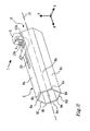
- the beam member 2 comprises a number of longitudinally-arranged folds 9a, 9b, 9c, 9d, 9e, 9f, see Fig. 2 .
- the beam member 2 is arranged with an opening 10 which is arranged to be faced upwards. Said opening is arranged for collaborating with said hood hinge 4 such that the hood hinge is able to move within the opening 10.
- the beam member 2 in the vehicle 7 has an orientation such that an end part 11, see Fig. 2 , of the beam member 2 is arranged adjacent to a front window/windshield 12 of the vehicle 7.
- the hood 5 is in an open position in Fig. 1 . In each corner area, at its rear end edge portion the hood 5 is connected to one hood hinge respectively.
- Fig. 2 shows the beam member assembly 1 adopted to be arranged in the vehicle 7, as shown in Fig. 1 .
- the beam member assembly 1 comprises a number of peripheral surfaces 8a, 8b, 8c, 8d, 8e, 8f adjoined together via the six longitudinal folds 9a, 9b, 9c, 9d, 9e, 9f forming a hollow profile of the beam member 1.
- Surfaces 8a, 8b, 8c, 8d, 8e, 8f are arranged between two adjacent longitudinal folds of said folds 9a, 9b, 9c, 9d, 9e, 9f a.
- the folds 9a, 9b, 9c, 9d, 9e, 9f are parallel with respect to each other in the beam member 1.
- the beam member 2 has a hexagonal shape.
- the hexagonal shape is advantageous upon an impact of body against the vehicle 7 creating an impact force having a direction intersecting with the longitudinal direction of the beam member assembly 1.
- said impacting force is of sufficient magnitude against the vehicle front part it will affect the beam member 2 such that the beam member 2 deforms at the point of impact on the beam member 2.
- the impacting force is absorbed within the beam member 2. Due to the hexagonal cross-section shape of the beam member 2, positions of at least three of said folds 9a, 9b, 9c, 9d, 9e, 9f on the beam member 2 are displaced near the location of the point of impact.
- At least two folds of said three folds will be moved in a direction away from a centre axis (14) through the beam member 2. At least one fold will be moved in a direction towards the centre axis (14).
- the folds 9a, 9b, 9c, 9d, 9e, 9f may, upon an impact, be described as functioning like a joint between two shafts connected with each other via their end portions. Upon an impact force causing a movement of one first shaft, the other, second shaft, is directly affected by the movements of the first shaft whereby the impacting force, which caused the movements, is being absorbed by the movements between the connected shafts.
- the beam member 2 has a closed cross-section.
- the closed cross-section provides for that a force acting against the beam member 2 can be distributed over the whole area of the beam member 2.
- a closed cross section is further of advantage upon extrusion of a beam.
- the beam member 2 is preferably made from aluminium.
- Aluminium is a material which has a fairly low cost and which is easy to machine and form as it is fairly soft compared to harder metallic materials such as e.g. iron. Even though aluminium is considered as a soft metallic material enough rigidity is achieved due to the hexagonal shape of the beam member 2.
- the opening 10 in the beam member assembly 1 is arranged such that it faces upwards.
- the opening 10 may be e.g. either machined or cut out from the elongated surfaces 8a arranged on an upper part of the beam member 2. A cut out may be made by e.g. milling or stamping.
- the opening 10 may be a so called closed hole, or a so-called open hole.
- the opening 10 being a closed hole has an edge portion surrounding the hole with the surface 8a. If the opening 10 instead is a so called open hole, the opening 10 has an open side not comprising an edge portion. It may for instance be a cut out which is open to the edge portion.
- the construction of an open hole may be made through the removal of a part of the surface 8a at the end part 11 of the beam member 2.
- the open hole may be exemplified as having the shape of a U.
- said opening being a so called open hole may be made in that the upper elongated surface 8a has a central position between two other arranged elongated surfaces 8b, 8f.
- the opening is achieved such that the central elongated surface 8a is displaced with respect to the two other surfaces thus creating an opening between said two surfaces 8b, 8f.
- the displacement of the central elongated surface may also be achieved in that the central elongated surface 8a is shorter than the two surfaces 8b, 8f, between which the central elongated surface 8a is arranged.
- the hood hinge 4 is arranged over the opening 10 having an elongation parallel with the longitudinal arrangement of the beam member 2.
- the hood hinge 4 is connected to the hood hinge bracket 3 via an axle-like member.
- the connection between the hood hinge 4 and the hood hinge bracket 3 allows the hood hinge 4 to be able to pivot with respect to the hood hinge bracket 3.
- the hood hinge bracket 3 is arranged to be connected on each side of the opening 10 via a respective connection area 13a, 13b.
- the connection areas 13a, 13b are substantially parallel to the folds 9a, 9b, 9c, 9d, 9e, 9f of the beam member 2.
- the hood hinge bracket 3 may be connected to the connection areas 13a, 13b e,g, by welding, brazing, gluing, fastening elements, or other means which would fix or attach the hood hinge bracket 3 to the beam member 2.
- the hood hinge bracket 3 and the hood hinge 4 must have such a connection with the beam member 2 that, upon an impact force having a direction towards the front part of the vehicle, the hood hinge bracket 3 and the hood hinge 4 must be able to withstand the force from the hood 5, to prevent the hood 5 from entering the front window 12 of the vehicle 7.
- the hood 5 is arranged to deform such that it folds in a direction towards the hood hinge bracket 3 and the hood hinge 4, without continuing into the front window 12.
- the opening 10 and the beam member assembly 1 are arranged such that when the hood 5 is in a closed position over the engine compartment 6, said hood hinge 4 is arranged within the interior of the beam member 2.
Landscapes
- Engineering & Computer Science (AREA)
- Mechanical Engineering (AREA)
- Chemical & Material Sciences (AREA)
- Combustion & Propulsion (AREA)
- Transportation (AREA)
- Superstructure Of Vehicle (AREA)
Claims (12)
- Trägerelementanordnung (1), die ein Trägerelement (2) mit einer longitudinalen Erstreckung und einen Haubenscharnierarm (3), an dem ein Haubenscharnier (4) zum Öffnen und Schließen einer Haube (5) eines Motorraums (6) eines Fahrzeugs (7) befestigt werden kann, umfasst, wobei das Trägerelement (2) ein Hohlprofil besitzt, das durch eine Umfangsoberfläche (8a, 8b, 8c, 8d, 8e, 8f) gebildet ist, die zahlreiche in Längsrichtung verlaufende Falze (9a, 9b, 9c, 9d, 9e, 9f) besitzt, wobei das Trägerelement (2) dazu ausgelegt ist, in Längsrichtung längs eines oberen Teils des Motorraums (6) zu verlaufen, dadurch gekennzeichnet, dass die Umfangsoberfläche (8a, 8b, 8c, 8d, 8e, 8f) eine Öffnung (10) besitzt, die zwischen zwei benachbarten Falzen (9a, 9b) angeordnet ist, wobei die Öffnung (10) und der Haubenscharnierarm (3) relativ zueinander so angeordnet sind, dass dann, wenn das Haubenscharnier (4) an dem Haubenscharnierarm (3) befestigt ist, das Haubenscharnier (4) zwischen einer Außenseite und einer Innenseite des Trägerelements (2) beweglich ist.
- Trägerelementanordnung (1) nach Anspruch 1, dadurch gekennzeichnet, dass das Trägerelement (2) sechs in Längsrichtung verlaufende Falze (9a, 9b, 9c, 9d, 9e, 9f) umfasst.
- Trägerelementanordnung (1) nach einem der Ansprüche 1-2, dadurch gekennzeichnet, dass die in Längsrichtung verlaufende Falze (9a, 9b, 9c, 9d, 9e, 9f) in dem Trägerelement (2) relativ zueinander parallel sind.
- Trägerelementanordnung (1) nach einem der Ansprüche 1-3, dadurch gekennzeichnet, dass das Trägerelement (2) eine im Wesentlichen sechseckige Querschnittsform besitzt.
- Trägerelementanordnung (1) nach einem der Ansprüche 1-4, dadurch gekennzeichnet, dass das Trägerelement (2) einen geschlossenen Querschnitt besitzt.
- Trägerelementanordnung (1) nach einem der Ansprüche 1-5, dadurch gekennzeichnet, dass das Trägerelement (2) aus Aluminium hergestellt ist.
- Fahrzeugvorderaufbau, der die Trägerelementanordnung (1) nach einem der vorhergehenden Ansprüche aufweist, dadurch gekennzeichnet, dass das Trägerelement (2) in dem Fahrzeug (7) so angeordnet ist, dass die Öffnung (10) nach oben weist.
- Fahrzeugvorderaufbau nach Anspruch 7, dadurch gekennzeichnet, dass die Öffnung (10) ein Ausschnitt ist.
- Fahrzeugvorderaufbau nach einem der Ansprüche 7-8, dadurch gekennzeichnet, dass die Öffnung (10) an einem Endabschnitt (11) des Trägerelements (2) angeordnet ist, wobei sich der Endabschnitt (11) in der Nähe einer Frontscheibe (12) des Fahrzeugs (7) befinden kann.
- Fahrzeugvorderaufbau nach einem der Ansprüche 7-9, dadurch gekennzeichnet, dass das Haubenscharnier (4) dafür ausgelegt ist, senkrecht zu der Längserstreckung der Öffnung (10) zu schwenken.
- Fahrzeugvorderaufbau nach einem der Ansprüche 7-10, dadurch gekennzeichnet, dass das Haubenscharnier (4) dann, wenn die Haube (5) in einer geschlossenen Stellung ist, innerhalb des Trägerelements (2) angeordnet ist.
- Fahrzeugvorderaufbau nach einem der Ansprüche 7-11, dadurch gekennzeichnet, dass der Haubenscharnierarm (3) an dem Trägerelement (2) über einen Verbindungsbereich (13a, 13b) an dem Trägerelement (2) befestigt ist, wobei der Verbindungsbereich (13a, 13b) eine Erstreckung besitzt, die zu den Falzen (9a, 9b, 9c, 9d, 9e, 9f) im Wesentlichen parallel ist.
Priority Applications (1)
| Application Number | Priority Date | Filing Date | Title |
|---|---|---|---|
| EP20100166311 EP2397630B1 (de) | 2010-06-17 | 2010-06-17 | Trägeranordnung mit einem Träger und einem Haubenscharnier für eine Motorhaube eines Fahrzeugs |
Applications Claiming Priority (1)
| Application Number | Priority Date | Filing Date | Title |
|---|---|---|---|
| EP20100166311 EP2397630B1 (de) | 2010-06-17 | 2010-06-17 | Trägeranordnung mit einem Träger und einem Haubenscharnier für eine Motorhaube eines Fahrzeugs |
Publications (2)
| Publication Number | Publication Date |
|---|---|
| EP2397630A1 EP2397630A1 (de) | 2011-12-21 |
| EP2397630B1 true EP2397630B1 (de) | 2013-01-02 |
Family
ID=42974851
Family Applications (1)
| Application Number | Title | Priority Date | Filing Date |
|---|---|---|---|
| EP20100166311 Not-in-force EP2397630B1 (de) | 2010-06-17 | 2010-06-17 | Trägeranordnung mit einem Träger und einem Haubenscharnier für eine Motorhaube eines Fahrzeugs |
Country Status (1)
| Country | Link |
|---|---|
| EP (1) | EP2397630B1 (de) |
Family Cites Families (3)
| Publication number | Priority date | Publication date | Assignee | Title |
|---|---|---|---|---|
| DE4417380C2 (de) * | 1994-05-18 | 1999-09-30 | Opel Adam Ag | Karosserievorderbau sowie Verfahren zur Montage einer Haubenscharniere aufweisenden Motorhaube eines Kraftfahrzeugs |
| EP1743827B1 (de) * | 2000-06-15 | 2011-01-19 | Toyota Jidosha Kabushiki Kaisha | Scharnierstruktur für Motorhaube |
| KR100482632B1 (ko) | 2003-04-12 | 2005-04-14 | 기아자동차주식회사 | 자동차용 후드 힌지 |
-
2010
- 2010-06-17 EP EP20100166311 patent/EP2397630B1/de not_active Not-in-force
Also Published As
| Publication number | Publication date |
|---|---|
| EP2397630A1 (de) | 2011-12-21 |
Similar Documents
| Publication | Publication Date | Title |
|---|---|---|
| JP5472223B2 (ja) | フェンダパネル取付構造 | |
| EP0921055B1 (de) | Fahrerhaus für eine Baumaschine | |
| JP5077541B2 (ja) | 車体前部構造 | |
| US9527463B2 (en) | Bumper assemblies including spacer members and vehicles incorporating the same | |
| EP1346887B1 (de) | Kotflügelstruktur | |
| EP1465786B1 (de) | Fahrzeugtür | |
| EP1972506B1 (de) | Befestigungsstruktur für fahrzeugunterfahrschutz | |
| CN101104395B (zh) | 车辆的前部结构 | |
| EP3665043A1 (de) | Polymerelement zur stossdämpfung für ein fahrzeug und stossfängerstruktur | |
| CA2483845A1 (en) | Collision energy-absorbing device | |
| JP2009137579A (ja) | ヒンジ | |
| JP2021160559A (ja) | 車両の前部車体構造 | |
| JP2017087766A (ja) | 車両前部構造 | |
| CN110316256A (zh) | 车辆前发动机罩用铰链臂安装构造 | |
| US20220242348A1 (en) | Bumper arrangement with end-side hollow profile | |
| JP7291456B2 (ja) | 建設機械のキャビン構造 | |
| CN207374522U (zh) | 用于作业机械的驾驶室框架和作业机械 | |
| JP4857595B2 (ja) | 自動車の前部車体構造 | |
| EP2397630A1 (de) | Trägeranordnung mit einem Träger und einem Haubenscharnier für eine Motorhaube eines Fahrzeugs | |
| JP2009137452A (ja) | 自動車用バンパー補強材 | |
| CN211493959U (zh) | 一种用于车辆的防撞梁总成 | |
| JP5038871B2 (ja) | 建設機械用キャビン | |
| JP4156987B2 (ja) | 運転室補強構造 | |
| JP2011213283A (ja) | 車両用フード構造 | |
| JP5236443B2 (ja) | 車体強度部材部構造 |
Legal Events
| Date | Code | Title | Description |
|---|---|---|---|
| AK | Designated contracting states |
Kind code of ref document: A1 Designated state(s): AL AT BE BG CH CY CZ DE DK EE ES FI FR GB GR HR HU IE IS IT LI LT LU LV MC MK MT NL NO PL PT RO SE SI SK SM TR |
|
| AX | Request for extension of the european patent |
Extension state: BA ME RS |
|
| PUAI | Public reference made under article 153(3) epc to a published international application that has entered the european phase |
Free format text: ORIGINAL CODE: 0009012 |
|
| 17P | Request for examination filed |
Effective date: 20120621 |
|
| GRAP | Despatch of communication of intention to grant a patent |
Free format text: ORIGINAL CODE: EPIDOSNIGR1 |
|
| RIC1 | Information provided on ipc code assigned before grant |
Ipc: B62D 25/12 20060101ALI20120724BHEP Ipc: E05D 5/06 20060101AFI20120724BHEP Ipc: B62D 25/08 20060101ALI20120724BHEP |
|
| GRAS | Grant fee paid |
Free format text: ORIGINAL CODE: EPIDOSNIGR3 |
|
| GRAA | (expected) grant |
Free format text: ORIGINAL CODE: 0009210 |
|
| AK | Designated contracting states |
Kind code of ref document: B1 Designated state(s): AL AT BE BG CH CY CZ DE DK EE ES FI FR GB GR HR HU IE IS IT LI LT LU LV MC MK MT NL NO PL PT RO SE SI SK SM TR |
|
| REG | Reference to a national code |
Ref country code: GB Ref legal event code: FG4D |
|
| REG | Reference to a national code |
Ref country code: AT Ref legal event code: REF Ref document number: 591732 Country of ref document: AT Kind code of ref document: T Effective date: 20130115 Ref country code: CH Ref legal event code: EP |
|
| REG | Reference to a national code |
Ref country code: IE Ref legal event code: FG4D |
|
| REG | Reference to a national code |
Ref country code: DE Ref legal event code: R096 Ref document number: 602010004388 Country of ref document: DE Effective date: 20130314 |
|
| REG | Reference to a national code |
Ref country code: SE Ref legal event code: TRGR |
|
| REG | Reference to a national code |
Ref country code: AT Ref legal event code: MK05 Ref document number: 591732 Country of ref document: AT Kind code of ref document: T Effective date: 20130102 |
|
| REG | Reference to a national code |
Ref country code: NL Ref legal event code: VDEP Effective date: 20130102 |
|
| PG25 | Lapsed in a contracting state [announced via postgrant information from national office to epo] |
Ref country code: SI Free format text: LAPSE BECAUSE OF FAILURE TO SUBMIT A TRANSLATION OF THE DESCRIPTION OR TO PAY THE FEE WITHIN THE PRESCRIBED TIME-LIMIT Effective date: 20130102 |
|
| REG | Reference to a national code |
Ref country code: LT Ref legal event code: MG4D |
|
| PG25 | Lapsed in a contracting state [announced via postgrant information from national office to epo] |
Ref country code: AT Free format text: LAPSE BECAUSE OF FAILURE TO SUBMIT A TRANSLATION OF THE DESCRIPTION OR TO PAY THE FEE WITHIN THE PRESCRIBED TIME-LIMIT Effective date: 20130102 Ref country code: BG Free format text: LAPSE BECAUSE OF FAILURE TO SUBMIT A TRANSLATION OF THE DESCRIPTION OR TO PAY THE FEE WITHIN THE PRESCRIBED TIME-LIMIT Effective date: 20130402 Ref country code: CZ Free format text: LAPSE BECAUSE OF FAILURE TO SUBMIT A TRANSLATION OF THE DESCRIPTION OR TO PAY THE FEE WITHIN THE PRESCRIBED TIME-LIMIT Effective date: 20130102 Ref country code: ES Free format text: LAPSE BECAUSE OF FAILURE TO SUBMIT A TRANSLATION OF THE DESCRIPTION OR TO PAY THE FEE WITHIN THE PRESCRIBED TIME-LIMIT Effective date: 20130413 Ref country code: NO Free format text: LAPSE BECAUSE OF FAILURE TO SUBMIT A TRANSLATION OF THE DESCRIPTION OR TO PAY THE FEE WITHIN THE PRESCRIBED TIME-LIMIT Effective date: 20130402 Ref country code: LT Free format text: LAPSE BECAUSE OF FAILURE TO SUBMIT A TRANSLATION OF THE DESCRIPTION OR TO PAY THE FEE WITHIN THE PRESCRIBED TIME-LIMIT Effective date: 20130102 Ref country code: BE Free format text: LAPSE BECAUSE OF FAILURE TO SUBMIT A TRANSLATION OF THE DESCRIPTION OR TO PAY THE FEE WITHIN THE PRESCRIBED TIME-LIMIT Effective date: 20130102 Ref country code: IS Free format text: LAPSE BECAUSE OF FAILURE TO SUBMIT A TRANSLATION OF THE DESCRIPTION OR TO PAY THE FEE WITHIN THE PRESCRIBED TIME-LIMIT Effective date: 20130502 |
|
| PG25 | Lapsed in a contracting state [announced via postgrant information from national office to epo] |
Ref country code: NL Free format text: LAPSE BECAUSE OF FAILURE TO SUBMIT A TRANSLATION OF THE DESCRIPTION OR TO PAY THE FEE WITHIN THE PRESCRIBED TIME-LIMIT Effective date: 20130102 Ref country code: GR Free format text: LAPSE BECAUSE OF FAILURE TO SUBMIT A TRANSLATION OF THE DESCRIPTION OR TO PAY THE FEE WITHIN THE PRESCRIBED TIME-LIMIT Effective date: 20130403 Ref country code: FI Free format text: LAPSE BECAUSE OF FAILURE TO SUBMIT A TRANSLATION OF THE DESCRIPTION OR TO PAY THE FEE WITHIN THE PRESCRIBED TIME-LIMIT Effective date: 20130102 Ref country code: PL Free format text: LAPSE BECAUSE OF FAILURE TO SUBMIT A TRANSLATION OF THE DESCRIPTION OR TO PAY THE FEE WITHIN THE PRESCRIBED TIME-LIMIT Effective date: 20130102 Ref country code: PT Free format text: LAPSE BECAUSE OF FAILURE TO SUBMIT A TRANSLATION OF THE DESCRIPTION OR TO PAY THE FEE WITHIN THE PRESCRIBED TIME-LIMIT Effective date: 20130502 Ref country code: LV Free format text: LAPSE BECAUSE OF FAILURE TO SUBMIT A TRANSLATION OF THE DESCRIPTION OR TO PAY THE FEE WITHIN THE PRESCRIBED TIME-LIMIT Effective date: 20130102 |
|
| PG25 | Lapsed in a contracting state [announced via postgrant information from national office to epo] |
Ref country code: HR Free format text: LAPSE BECAUSE OF FAILURE TO SUBMIT A TRANSLATION OF THE DESCRIPTION OR TO PAY THE FEE WITHIN THE PRESCRIBED TIME-LIMIT Effective date: 20130102 |
|
| PG25 | Lapsed in a contracting state [announced via postgrant information from national office to epo] |
Ref country code: EE Free format text: LAPSE BECAUSE OF FAILURE TO SUBMIT A TRANSLATION OF THE DESCRIPTION OR TO PAY THE FEE WITHIN THE PRESCRIBED TIME-LIMIT Effective date: 20130102 Ref country code: DK Free format text: LAPSE BECAUSE OF FAILURE TO SUBMIT A TRANSLATION OF THE DESCRIPTION OR TO PAY THE FEE WITHIN THE PRESCRIBED TIME-LIMIT Effective date: 20130102 Ref country code: RO Free format text: LAPSE BECAUSE OF FAILURE TO SUBMIT A TRANSLATION OF THE DESCRIPTION OR TO PAY THE FEE WITHIN THE PRESCRIBED TIME-LIMIT Effective date: 20130102 Ref country code: SK Free format text: LAPSE BECAUSE OF FAILURE TO SUBMIT A TRANSLATION OF THE DESCRIPTION OR TO PAY THE FEE WITHIN THE PRESCRIBED TIME-LIMIT Effective date: 20130102 |
|
| PLBE | No opposition filed within time limit |
Free format text: ORIGINAL CODE: 0009261 |
|
| STAA | Information on the status of an ep patent application or granted ep patent |
Free format text: STATUS: NO OPPOSITION FILED WITHIN TIME LIMIT |
|
| PG25 | Lapsed in a contracting state [announced via postgrant information from national office to epo] |
Ref country code: CY Free format text: LAPSE BECAUSE OF FAILURE TO SUBMIT A TRANSLATION OF THE DESCRIPTION OR TO PAY THE FEE WITHIN THE PRESCRIBED TIME-LIMIT Effective date: 20130102 |
|
| 26N | No opposition filed |
Effective date: 20131003 |
|
| PG25 | Lapsed in a contracting state [announced via postgrant information from national office to epo] |
Ref country code: IT Free format text: LAPSE BECAUSE OF FAILURE TO SUBMIT A TRANSLATION OF THE DESCRIPTION OR TO PAY THE FEE WITHIN THE PRESCRIBED TIME-LIMIT Effective date: 20130102 |
|
| REG | Reference to a national code |
Ref country code: DE Ref legal event code: R097 Ref document number: 602010004388 Country of ref document: DE Effective date: 20131003 |
|
| PG25 | Lapsed in a contracting state [announced via postgrant information from national office to epo] |
Ref country code: MC Free format text: LAPSE BECAUSE OF FAILURE TO SUBMIT A TRANSLATION OF THE DESCRIPTION OR TO PAY THE FEE WITHIN THE PRESCRIBED TIME-LIMIT Effective date: 20130102 |
|
| REG | Reference to a national code |
Ref country code: IE Ref legal event code: MM4A |
|
| REG | Reference to a national code |
Ref country code: FR Ref legal event code: ST Effective date: 20140228 |
|
| PG25 | Lapsed in a contracting state [announced via postgrant information from national office to epo] |
Ref country code: IE Free format text: LAPSE BECAUSE OF NON-PAYMENT OF DUE FEES Effective date: 20130617 |
|
| PG25 | Lapsed in a contracting state [announced via postgrant information from national office to epo] |
Ref country code: FR Free format text: LAPSE BECAUSE OF NON-PAYMENT OF DUE FEES Effective date: 20130701 |
|
| REG | Reference to a national code |
Ref country code: CH Ref legal event code: PL |
|
| PG25 | Lapsed in a contracting state [announced via postgrant information from national office to epo] |
Ref country code: MT Free format text: LAPSE BECAUSE OF FAILURE TO SUBMIT A TRANSLATION OF THE DESCRIPTION OR TO PAY THE FEE WITHIN THE PRESCRIBED TIME-LIMIT Effective date: 20130102 |
|
| PG25 | Lapsed in a contracting state [announced via postgrant information from national office to epo] |
Ref country code: CH Free format text: LAPSE BECAUSE OF NON-PAYMENT OF DUE FEES Effective date: 20140630 Ref country code: LI Free format text: LAPSE BECAUSE OF NON-PAYMENT OF DUE FEES Effective date: 20140630 |
|
| PG25 | Lapsed in a contracting state [announced via postgrant information from national office to epo] |
Ref country code: SM Free format text: LAPSE BECAUSE OF FAILURE TO SUBMIT A TRANSLATION OF THE DESCRIPTION OR TO PAY THE FEE WITHIN THE PRESCRIBED TIME-LIMIT Effective date: 20130102 |
|
| PG25 | Lapsed in a contracting state [announced via postgrant information from national office to epo] |
Ref country code: TR Free format text: LAPSE BECAUSE OF FAILURE TO SUBMIT A TRANSLATION OF THE DESCRIPTION OR TO PAY THE FEE WITHIN THE PRESCRIBED TIME-LIMIT Effective date: 20130102 |
|
| PG25 | Lapsed in a contracting state [announced via postgrant information from national office to epo] |
Ref country code: LU Free format text: LAPSE BECAUSE OF NON-PAYMENT OF DUE FEES Effective date: 20130617 Ref country code: HU Free format text: LAPSE BECAUSE OF FAILURE TO SUBMIT A TRANSLATION OF THE DESCRIPTION OR TO PAY THE FEE WITHIN THE PRESCRIBED TIME-LIMIT; INVALID AB INITIO Effective date: 20100617 Ref country code: MK Free format text: LAPSE BECAUSE OF FAILURE TO SUBMIT A TRANSLATION OF THE DESCRIPTION OR TO PAY THE FEE WITHIN THE PRESCRIBED TIME-LIMIT Effective date: 20130102 |
|
| PG25 | Lapsed in a contracting state [announced via postgrant information from national office to epo] |
Ref country code: AL Free format text: LAPSE BECAUSE OF FAILURE TO SUBMIT A TRANSLATION OF THE DESCRIPTION OR TO PAY THE FEE WITHIN THE PRESCRIBED TIME-LIMIT Effective date: 20130102 |
|
| PGFP | Annual fee paid to national office [announced via postgrant information from national office to epo] |
Ref country code: SE Payment date: 20190620 Year of fee payment: 10 |
|
| PGFP | Annual fee paid to national office [announced via postgrant information from national office to epo] |
Ref country code: GB Payment date: 20190613 Year of fee payment: 10 |
|
| GBPC | Gb: european patent ceased through non-payment of renewal fee |
Effective date: 20200617 |
|
| PG25 | Lapsed in a contracting state [announced via postgrant information from national office to epo] |
Ref country code: GB Free format text: LAPSE BECAUSE OF NON-PAYMENT OF DUE FEES Effective date: 20200617 |
|
| PG25 | Lapsed in a contracting state [announced via postgrant information from national office to epo] |
Ref country code: SE Free format text: LAPSE BECAUSE OF NON-PAYMENT OF DUE FEES Effective date: 20200618 |
|
| REG | Reference to a national code |
Ref country code: SE Ref legal event code: EUG |
|
| P01 | Opt-out of the competence of the unified patent court (upc) registered |
Effective date: 20231212 |
|
| PGFP | Annual fee paid to national office [announced via postgrant information from national office to epo] |
Ref country code: DE Payment date: 20240521 Year of fee payment: 15 |
|
| REG | Reference to a national code |
Ref country code: DE Ref legal event code: R119 Ref document number: 602010004388 Country of ref document: DE |
|
| PG25 | Lapsed in a contracting state [announced via postgrant information from national office to epo] |
Ref country code: DE Free format text: LAPSE BECAUSE OF NON-PAYMENT OF DUE FEES Effective date: 20260101 |