EP2397624B1 - Système et procédé de formation d'un revêtement de sol en panneaux standard et au moins un panneau de remplacement - Google Patents
Système et procédé de formation d'un revêtement de sol en panneaux standard et au moins un panneau de remplacement Download PDFInfo
- Publication number
- EP2397624B1 EP2397624B1 EP11168873.5A EP11168873A EP2397624B1 EP 2397624 B1 EP2397624 B1 EP 2397624B1 EP 11168873 A EP11168873 A EP 11168873A EP 2397624 B1 EP2397624 B1 EP 2397624B1
- Authority
- EP
- European Patent Office
- Prior art keywords
- panel
- standard
- connecting element
- panel body
- profile
- Prior art date
- Legal status (The legal status is an assumption and is not a legal conclusion. Google has not performed a legal analysis and makes no representation as to the accuracy of the status listed.)
- Active
Links
Images

Classifications
-
- E—FIXED CONSTRUCTIONS
- E04—BUILDING
- E04F—FINISHING WORK ON BUILDINGS, e.g. STAIRS, FLOORS
- E04F15/00—Flooring
- E04F15/02—Flooring or floor layers composed of a number of similar elements
-
- E—FIXED CONSTRUCTIONS
- E04—BUILDING
- E04G—SCAFFOLDING; FORMS; SHUTTERING; BUILDING IMPLEMENTS OR AIDS, OR THEIR USE; HANDLING BUILDING MATERIALS ON THE SITE; REPAIRING, BREAKING-UP OR OTHER WORK ON EXISTING BUILDINGS
- E04G23/00—Working measures on existing buildings
- E04G23/02—Repairing, e.g. filling cracks; Restoring; Altering; Enlarging
- E04G23/0285—Repairing or restoring flooring
-
- E—FIXED CONSTRUCTIONS
- E04—BUILDING
- E04F—FINISHING WORK ON BUILDINGS, e.g. STAIRS, FLOORS
- E04F2201/00—Joining sheets or plates or panels
- E04F2201/01—Joining sheets, plates or panels with edges in abutting relationship
- E04F2201/0138—Joining sheets, plates or panels with edges in abutting relationship by moving the sheets, plates or panels perpendicular to the main plane
-
- E—FIXED CONSTRUCTIONS
- E04—BUILDING
- E04F—FINISHING WORK ON BUILDINGS, e.g. STAIRS, FLOORS
- E04F2201/00—Joining sheets or plates or panels
- E04F2201/01—Joining sheets, plates or panels with edges in abutting relationship
- E04F2201/0153—Joining sheets, plates or panels with edges in abutting relationship by rotating the sheets, plates or panels around an axis which is parallel to the abutting edges, possibly combined with a sliding movement
-
- E—FIXED CONSTRUCTIONS
- E04—BUILDING
- E04F—FINISHING WORK ON BUILDINGS, e.g. STAIRS, FLOORS
- E04F2201/00—Joining sheets or plates or panels
- E04F2201/04—Other details of tongues or grooves
- E04F2201/041—Tongues or grooves with slits or cuts for expansion or flexibility
-
- E—FIXED CONSTRUCTIONS
- E04—BUILDING
- E04F—FINISHING WORK ON BUILDINGS, e.g. STAIRS, FLOORS
- E04F2201/00—Joining sheets or plates or panels
- E04F2201/04—Other details of tongues or grooves
- E04F2201/042—Other details of tongues or grooves with grooves positioned on the rear-side of the panel
-
- E—FIXED CONSTRUCTIONS
- E04—BUILDING
- E04F—FINISHING WORK ON BUILDINGS, e.g. STAIRS, FLOORS
- E04F2201/00—Joining sheets or plates or panels
- E04F2201/05—Separate connectors or inserts, e.g. pegs, pins, keys or strips
- E04F2201/0517—U- or C-shaped brackets and clamps
-
- E—FIXED CONSTRUCTIONS
- E04—BUILDING
- E04F—FINISHING WORK ON BUILDINGS, e.g. STAIRS, FLOORS
- E04F2201/00—Joining sheets or plates or panels
- E04F2201/05—Separate connectors or inserts, e.g. pegs, pins, keys or strips
- E04F2201/0523—Separate tongues; Interlocking keys, e.g. joining mouldings of circular, square or rectangular shape
Definitions
- the invention relates to a system for forming a floating floor covering, with a plurality of similar standard panels and at least onesistedpaneel, wherein the standard panels each have on at least two opposite narrow sides corresponding to each other formed first and second connection profiles and wherein the handheldpaneel one with the first connection profile a standard panel has correspondingly formed first connection profile.
- the invention also relates to a floor covering having at least one replacement panel and to a method of replacing at least one standard panel of a floating floor covering with at least one replacement panel.
- Floating laid composed of a plurality of standard panels
- floor coverings are known in different designs. Under a floating laid floor covering is understood to mean one that is not or at least not permanently connected to the ground.
- the standard panels of corresponding floor coverings are rectangular and each comprise two opposite short and long narrow sides. On the short and long narrow sides are each correspondingly formed connecting profiles provided.
- the connection profiles correspond so that similar standard panels on short and long narrow side pairs can be connected together to form a floor covering. If necessary, the connection profiles on the short and long side edges are formed similar to each other, so that even long narrow sides can be connected with short narrow sides of similar standard panels.
- connection profiles are usually designed such that the similar standard panels are locked together when connecting.
- the use of an adhesive for permanently connecting the standard panels can therefore be dispensed with.
- Modern standard panels have connecting profiles which are locked together in a vertical direction as well as in a horizontal direction perpendicular to the respective connection profiles. So high quality floors can be obtained.
- the locking of the connection profiles with one another can take place by being bent in, by essentially horizontal snapping in and / or by a substantially vertical movement, which, as when snapping in, leads to a locking of the connection profiles.
- the standard panels are not glued together, it is only possible with great effort to replace a damaged standard panel of a laid floor covering. In many cases, it is necessary to resume the standard panels in the reverse order of their laying until the damaged standard panel is removed. Then the damaged standard panel is replaced with a new standard panel, and the part of the floor covering picked up again. Another possibility is to disassemble the damaged standard panel and to remove it in parts from the floor covering. The removed standard panel is then replaced by a new standard panel, in which previously parts of the connection profiles have been removed, so that the new standard panel can be integrated from above into the gap of the floor covering. However, the connection profiles of the new standard panel can then no longer or only to a limited extent be locked with other adjacent standard panels. Therefore, the new standard panel must be glued at least on individual narrow sides with the adjacent standard panels.
- the repair kit includes an exchange panel, which can be retrofitted to replace a damaged panel in an existing floor covering.
- the replacement panel has no spring, but grooves on all four circumferential narrow sides. In two of these grooves are provided flexible foreign elements, which can cooperate in the sense of a spring with grooves adjacent standard panels for the purpose of locking.
- WO 03/083234 A1 a composite of similar panels floor covering. Individual of these panels can be resumed after installation and replaced as needed by other panels. The laying and retrieval of the panels can be done by a substantially vertical movement. For this purpose, the panels on flexible locking means which are provided in corresponding grooves of certain narrow sides. Also in the WO 01/98603 A1 is a floor covering of similar panels described in which the panels can be separated again after laying. For this purpose, the locking profiles of the panels are on the one hand designed so that the panels are locked together in the connected state. On the other hand, these compounds can be solved by raising individual panels of the floor covering and the associated pivoting the same, so that the raised panels can be replaced as needed by new panels. Other floor coverings are off WO 2004/003314 A1 . WO 01/66877 A1 such as US 2010/0031594 A1 known. A similar system and procedure is off JP 2000-320109 A known.
- the present invention is therefore based on the technical problem of proposing a possibility for the subsequent replacement of individual floor panels, in which the known disadvantages do not occur or at least in a weakened form.
- the replacement panel differs from the standard panels and comprises at least one panel body and at least one connecting element, that the first connection profile of thefoundpaneels is at least partially formed by the connecting element and that the connecting element and the panel body by a substantially vertical Movement of the panel body mechanically lockable with each other, have corresponding locking profiles.
- the replacement panel is thus designed in several parts and, in addition to a panel body, comprises at least one connecting element.
- the panel body substantially forms the part of the replacement panel visible in the condition installed in the floor covering.
- the at least one connecting element can also be visible from above in the connected state, this is preferably less, since this would regularly lead to a visual impairment of the floor covering.
- the panel body itself is composed of several components. However, this is less preferred for optical reasons.
- the connecting element serves to connect the panel body to an adjacent standard panel of the floor covering. Therefore, the first connection profile of the replacement panel is also formed at least in part by the connection element.
- the connecting element is to remain invisible from the top of the floor covering, it makes sense if at least the upper edge of the first connecting profile is formed by the panel body. It is particularly useful if at least the lower part of the first Connection profile is formed by the connecting element. This lower part of the first connection profile can be easily provided by the separate connection element. Since the peripheral connection profiles of thebotpaneels not necessarily with each other, ie with other similarlepaneelen must be connectable, unlike the standard panels of the floor covering, the corresponding connection profiles may on the one hand differ from the corresponding connection profiles of the standard panels and on the other hand be designed to correspond with each other so that similar Replacement panels can not be connected. There may therefore also be slight differences between the connection profiles of the replacement panel and the corresponding connection profiles of the standard panels.
- a repair kit for forming a multi-part replacement panel for the replacement of a panel of a floating floor covering, wherein thebotpaneel at least one panel body and at least one connecting element, wherein thebotpaneel in an assembled state on two opposite narrow sides, a first connection profile and a second connection profile, wherein the first and the second connection profile are formed corresponding to each other, so that the first and the second connection profile similar Replacement panels can be interconnected.
- at least part of the first connection profile is formed by the connection element, while the connection element and the panel body have latching profiles that can be mechanically locked together by a substantially vertical movement of the panel body.
- At least the first connection profile of the replacement panel is nevertheless formed corresponding to a first connection profile of the standard panel in such a way that the first connection profiles can be connected to one another.
- the second connection profile of the replacement panel will also be designed corresponding to a second connection profile of the standard panel, so that the second connection profiles can be connected to one another.
- first and the second connection profile of the replacement panel at least substantially correspond to the first and the second connection profile of the standard panels.
- the corresponding connection profiles ofsimilarpaneel and Standardpaneel can therefore be formed if necessary similar.
- claim 15 also by a floating floor covering, comprising a system according to at least one of claims 1 to 14.
- preferred features relating to the replacement panel itself may be related to the repair kit, even if the features are generally described for the system.
- the repair kit and the replacement panel formed therefrom may also comprise further separate components, such as at least one supplementary spring and / or at least one further connecting element.
- the supplementary spring forms, for example, a part of the second connection profile of the replacement panel, while the second connection element forms, for example, a part of the third connection profile of the replacement panel.
- the standard panel can be split into two or more parts, which can then be removed from the original floor covering without having to accept or damage adjacent standard panels. Since thesensorpaneel in one piece can not or only with great effort in the resulting by removing the one, preferably damaged, standard panel gap in the floor covering can be introduced, the antennaeel comprises a panel body and at least one connecting element.
- the connecting element is connected to the first connection profile of the standard panel adjoining the corresponding location.
- the connecting element preferably already a mechanical locking in a vertical direction and / or in a horizontal direction perpendicular to the corresponding first Locking profile reached.
- the connecting element is positioned only with respect to the adjacent first connecting profile of a standard panel, but not also connected or locked with this.
- the locking of the first connection profiles of exchange panel and standard panel is then preferably carried out with the addition of the panel body.
- the panel body then preferably completes the first connection profile of the replacement panel.
- the completed first connection profile is substantially identical to a connection profile of the standard panel, in particular to the second connection profile on the opposite side of the first connection profile narrow side of the standard panel.
- the panel body After the connecting element is provided in a suitable position, the panel body can be easily, accurately and quickly added and firmly connected to the connecting element. In this way, the necessary strength of the floor covering is achieved. Is theoutpaneel only from the panel body and the one connecting element, so that the gap is filled in the floor covering and it is again obtained a floor covering with uniform appearance.
- the connecting element and the panel body respectively Locking profile on.
- the locking profiles are formed corresponding to each other and coordinated so that the panel body can be mechanically locked by a substantially vertical movement of the same with the connecting element.
- the mechanical locking between the locking profiles of panel body and connecting element acts in at least one direction, so that the panel body and the connecting element are firmly connected to each other in this direction.
- a vertical direction is understood to be a direction perpendicular to the floor covering for the sake of simplicity. It is assumed that the floor covering is basically arranged in a horizontal plane. However, this is not absolutely necessary, so that the vertical direction and / or the horizontal direction can deviate from an objective vertical and / or horizontal. However, for the sake of simplicity, only vertical direction and horizontal direction will be discussed below, even if these directions do not necessarily have to be horizontal or vertical in the usual sense.
- the movement for locking the panel body and connecting element takes place exactly vertically relative to the floor covering. It may be sufficient if the movement is only substantially vertical to the floor covering.
- the movement has a predominantly vertical component, but can also be slightly oblique.
- a Einwinkelterrorism wherein the panel body in an oblique position in a connection profile or locking profile pushed and then pivoted down to the corresponding narrow side of the panel body to the ground, are regarded as substantially vertical movement with respect to the other narrow sides of the panel body.
- the connection profiles or locking profiles on the other three narrow sides of the panel body then still perform a substantially vertical movement.
- the first connection profiles of thelowpaneel and the standard panel are formed in a vertical direction and in a horizontal direction perpendicular to the first connection profiles locked together.
- the replacement panel and the adjacent standard panel are thus opposite to a mutual lift-off, i. secured in the vertical direction, and against a withdrawal in the horizontal direction.
- the locking profiles of the connecting element and the panel body in a vertical direction and in a horizontal direction perpendicular to the locking profiles may be formed locked together. This also allows a better cohesion between the panel body and the connecting element. A separation of the panel body and connecting element is counteracted in both directions by the mutual locking.
- the locking profile of the Connecting element have a locking latch for forming a latching connection with the panel body.
- the locking bolt of the connecting element is preferably designed such that it brings about a latching connection with the panel body, which acts at least predominantly in the vertical direction.
- the locking bar may preferably extend predominantly in the vertical direction and relative to the floor covering from top to bottom.
- the locking bar could also be provided on the locking profile of the panel body, which is fundamentally less preferred for material reasons.
- the locking bolt In the connected state, the locking bolt is supported alternatively or additionally relative to the panel body, in particular a latching projection of the panel body from. In this case, corresponding locking surfaces of the locking bolt and the locking profile of the panel body abut each other in the connected state.
- the locking bar is preferably adapted to be bent and / or pivoted during the connection of the connecting element and panel body by a substantially vertical movement of the panel body in the direction of the connecting element.
- the connecting element and the panel body may have two first fitting surfaces which cooperate in the connected state.
- the first mating surfaces are then preferably designed so that in the connected state the panel body rests with the first mating surface on the first mating surface of the connecting element.
- the panel body thus supports itself in the vertical direction via the first mating surfaces on the connecting element.
- the first fitting surface of the connecting element is preferably provided on a groove base of a substantially vertically aligned fitting groove, while the first fitting surface of the panel body is provided on a substantially vertically oriented key. So a defined investment of the first mating surfaces can be ensured together.
- the first fitting surface of the panel body can be provided on a groove bottom of a substantially vertically aligned fitting groove and the first fitting surface of the connecting element on a substantially vertically aligned key.
- the connecting element and the panel body may have two second mating surfaces.
- the second mating surfaces are then preferably designed so that they effect a locking in a horizontal extension direction perpendicular to the locking profiles of the connecting element and the panel body in the connected state.
- the second mating surfaces in the connected state abut each other.
- the second mating surface of the connecting element or the Panel be provided on a groove flank of the fitting groove.
- the locking in the aforementioned extension direction is an inner groove flank.
- the second mating surface of the connecting element or the panel body is provided on a spring edge of the feather key.
- this spring flank is preferably the inner spring flank.
- a second connection profile of the replacement panel can have a supplementary spring corresponding to the second connection profile of a standard panel.
- the second connection profile of the replacement panel is preferably provided opposite the first connection profile of the replacement panel.
- the supplementary spring is connected in the connected state similar to the connecting element with the panel body.
- connection of the second connection profiles of the replacement panel and the adjacent standard panel can be brought about in a simple manner by a substantially vertical movement of the panel body.
- the supplemental spring and the panel member may therefore be configured to connect the second connection profile of the replacement panel to the second connection panel of an adjacent standard panel by a substantially vertical movement of the panel body.
- This vertical movement is preferably the same vertical movement of the panel body to connect the first one Connection profile of thebotpaneels with the first connection profile of the adjacent standard panel.
- the first and second connection profiles can then be connected to one and the same vertical movement of the panel body.
- the supplementary spring it is not necessary that this, without being held by the second connection profile of the standard panel, is independently connectable to the panel body. It is essential that a connection between the wornpaneel and the corresponding standard panel is made.
- the supplementary spring can preferably be inserted into a groove of the second connection profile of another adjacent standard panel.
- the second connection profile of the replacement panel is then mechanically locked in a further step by a substantially vertical movement of the panel body with the second connection profile of the other, originally adjacent to the standard panel removed standard panel.
- the supplementary spring may have a locking latch for forming a latching connection with the panel body.
- the locking bolt of the supplementary spring is preferably designed such that it brings about a latching connection with the panel body, which acts at least predominantly in the vertical direction. Lifting the panel body upwards is then no longer possible after the connection.
- the locking bar may preferably predominantly in vertical Direction and extend based on the floor covering from top to bottom.
- the locking bolt In the connected state, the locking bolt is supported alternatively or additionally relative to the panel body, in particular a corresponding latching projection of the panel body from. In this case, corresponding locking surfaces of the locking bolt and the panel body abut each other in the connected state.
- the locking bar is preferably adapted to be bent and / or pivoted during connection by a substantially vertical movement of the panel body in the direction of the supplementary spring or away from the panel body.
- Adjacent to the locking bar of the supplementary spring and / or the connecting element may be provided a Elastizticiansnut. This can give the locking bolt the necessary for the formation of a locking connection elasticity.
- the elasticity groove may be at least partially filled with an elastic material. The elastic material is at least temporarily compressed when joined by the substantially vertical movement of the panel body. In the connected state, the elastic material can then remain partially compressed. This is not necessary.
- Locking bar of the connecting element and / or the supplementary spring be provided a hinge forming a constriction.
- the supplementary spring can have at least one stop surface for supporting the supplementary spring with respect to the second connecting profile of the standard panel have in the vertical and / or horizontal direction perpendicular to the second connection profile.
- the at least one stop surface of the supplementary spring can be inclined to the vertical and to the horizontal in order to achieve a support of the supplementary spring both partially in the vertical and partly in the horizontal direction.
- the additional spring has three separate stop surfaces, which rest in the connected state on the second connection profile of the standard panel.
- a stop surface, the supplementary spring down and another stop surface support the supplementary spring upwards relative to the second connection profile of the standard panel. Consequently, these first two abutment surfaces are preferably aligned substantially horizontally.
- the third abutment surface of the supplementary spring then preferably supports it in the horizontal direction towards the second connection profile of the standard panel in relation to the same. Consequently, this third abutment surface is preferably oriented substantially vertically.
- all three abutment surfaces rest on the second connection profile of the standard panel. It is further preferred in this context if the supplementary spring is received in a substantially horizontally oriented groove of the second connection profile of the standard panel. Then, at least the first two abutment surfaces for supporting the supplementary spring in a vertical direction in the groove on the standard panel abut.
- Thepedpaneel which is preferably rectangular, still has a third and a fourth narrow side.
- a further connection profile may be provided for connection to further replacement panels and / or further standard panels.
- the corresponding connection profiles can be formed in one piece, ie without further connection element and / or without additional supplementary spring.
- the connection profiles may be designed to be connected by a substantially vertical or horizontal movement and / or by a pivoting movement with other connection profiles.
- the third and fourth connection profiles of the replacement panel are in particular similar to the third and fourth connection profiles of the standard panels, in order to facilitate the connection of the replacement panel to other standard panels.
- the replacement panel may comprise a second connection element which at least partially forms the third connection profile of the replacement panel.
- the second connection element and the panel body may be formed such that the second connection element and the panel body can be mechanically locked to one another in a simple manner by a substantially vertical movement of the panel body, for which purpose the second connection element and the panel body have corresponding locking profiles.
- first and the third connection profiles of the standard panels and the replacement panel are of similar construction.
- first and the second connection element may be formed similar.
- the first and the second are different Connecting element then, for example, only by their length, which simplifies the production of the first and second connecting elements.
- first and second connection profiles and / or the third and fourth connection profiles of the standard panels may be provided for joining them by angling, substantially horizontally snapping and / or by a substantially vertical movement of a standard panel.
- first, second, third and / or fourth connection profile need not be connected in the same way with the first, second, third and / or fourth connection profile of the replacement panel, as is the case with the standard panels. So usually a horizonatles snapping separates for reasons of space.
- connection profiles of an exchange panel because of the already laid adjacent standard panels.
- Such connections are also not mandatory, since thezeleel comprises at least one separate connection element.
- the panel body is connected to at least one connecting element and / or with at least one standard panel, for example by angling.
- This one-angle movement can then represent a substantially vertical movement of the panel body relative to a locking profile of another narrow side or the other locking profiles on other narrow sides.
- the at least one connecting element and / or the at least one supplementary spring is preferably a component made of plastic, which can be manufactured inexpensively as an extrusion component.
- the panel body is preferably formed of the same material as the standard panels.
- the core of the panel body is preferably made of a wood material, such as a medium-density fiberboard, a high-density fiberboard, an Oriented beach board board chipboard, made of a plate of a wood / plastic composite (WPC) and / or a compact laminate ,
- WPC wood / plastic composite
- the panel body preferably has a coating known from the prior art, in particular laminate coating.
- the coating of the panel body and the standard panels is identical or similar.
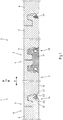
- a system 1 of a floor covering 2 of several panels is shown in a connected state.
- the floor covering 2 is laid floating and therefore not connected to the ground.
- a lostpaneel 3 is shown, which is connected to two opposite narrow sides 4,5 with standard panels 6, which are shown on both sides of thefoundpaneels 3.
- the standard panels 6 are similar to each other and have at the two opposing narrow sides 7,8 shown first connection profiles 9 and second connection profiles 10 which are formed corresponding to each other, so that the standard panels 6 with each other with the first and the second connection profiles 9,10 can be connected.
- connection profiles 9, 10 of the standard panels 6 are thereby locked together in a vertical direction V and in a horizontal direction H perpendicular to the connection profiles 9, 10. This can be achieved by a substantially vertical movement of a standard panel 6 newly added to the floor covering.
- a single standard panel 6 can be replaced almost independently of its position in the floor covering 2.
- the exchange panel 3 is constructed in several parts and comprises in the illustrated and so far preferred system 1 at least one panel body 11 and a connecting element 12.
- the panel body 11 is made using the same materials as the standard panels 6, so that the replacement panel 3 of the floor covering in the connected state not such is recognizable.
- the connecting element 12 is formed from plastic and in the present case produced as an extrusion component.
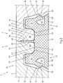
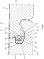
- the connecting element 12 which as an enlarged detail of thenetpaneels 3 and the floor covering 2 in Fig. 2 is formed, forms part of the first connection profile 13 of the exchange panel 3. Only the upper portion of the first connection profile 13 is formed by the panel body 11.
- the first connection profile 13 is designed corresponding to the adjacent first connection profile 9 of the standard panel 6, so that the first connection profiles 9, 13 can be connected to one another. In the connected state, the first connection profiles 9,13 in a vertical direction V and a horizontal direction H are locked together.
- a second connection profile 14 is provided, which is formed corresponding to the second connection profile 10 of the standard panels 6, so that the second connection profiles 10,14 in a vertical direction V and a horizontal Direction H can be locked together.
- the second connection profile 14 of the replacement panel 3 is formed substantially identically to the first connection profile 9 of the standard panel 6.
- the connecting element 12 When inserting thecertainpaneels 3 in a gap of the floor covering 2, which has arisen that previously a standard panel 6 has been removed from the floor covering 2, the connecting element 12 is first inserted into the gap.
- the connecting element 12 has a substantially vertically upwardly directed key 15, which is inserted from below into a fitting groove 16 of the first connecting profile 9 of the adjacent standard panel 6.
- the floor covering 2 must be slightly raised in the appropriate place.
- a locking bolt 17 of the connecting element 12 locks with the first connecting profile 9 of the adjacent standard panel 6, in particular with a locking projection 18 thereof.
- locking surfaces 19,20 of the locking bolt 17 and the latching projection 18 abut each other. In this way, a vertical locking of the connecting element 12 with the adjacent standard panel 6 is achieved.
- the locking surfaces 19,20 are significantly inclined relative to the horizontal.
- first mating surfaces 21, 22 of the first connection profile 13 of the replacement panel 3 and of the first connection profile 9 of the standard panel 6 come into contact with one another.
- the standard panel 6 is supported against the connecting member 12.
- locking of the first connection profiles 9, 13 in a horizontal extension direction perpendicular to the first connection profiles 9, 13 is achieved.
- the connecting element 12 has a positioning projection 26, which forms a third fitting surface 27 of the first connecting profile 13 against which a third fitting surface 28 of the adjacent standard panel 6 abuts.
- the positioning projection 26 would basically be dispensable. Then, however, would also be waived on the corresponding mating surfaces.
- the first mating surface 22 of the first connection profile 9 of the standard panel 6 is provided at a distal end of the key 30, while the inner spring edge of the key 30, the second mating surface 24 and the outer spring edge of the key 30 has the third mating surface 28.
- the first fitting surface 23 of the first connection profile 13 of the connecting element 12 is provided on a groove bottom of a fitting groove 31 into which the feather key 30 of the standard panel 6 engages.
- the second fitting surface 23 of the connecting element 12 is provided on an outer groove flank of the fitting groove 31 and the third fitting surface 27 on an inner groove flank of the fitting groove 31 of the first connecting profile 13.
- this On the side facing away from the first connection profile 13 side of the connecting element, this has a locking profile 33 which the locking of the connecting element 12 with a locking profile 34 of the panel body 11 is used after the connecting element 12 has been connected to the adjacent standard panel 6.
- the locking profiles 33,34 of connecting element 12 and panel body 11 are formed corresponding to each other.
- the joining of the panel body 11 with the connecting element 12 is effected by a substantially vertical movement of the panel body 11.
- the locking profile 13 of the connecting element 12 has a locking bolt 35 which cooperates with a latching projection 36 of the locking profile 34 of the panel body 11.
- the latching projection 36 has a locking surface 37 which rests in the connected state on a locking surface 38 of the locking bolt 35.
- the required elasticity of the locking bolt 17,35,40 of Standardpaneel 6 and connecting element 12 is achieved by the elasticity 42,43,44, which are provided adjacent to the respective Sperrriegeln 17,35,40.
- Each elasticity groove 42,43,44 may be at least partially filled by an elastic material 45 to adjust the elasticity. This is provided in the standard panels 6.
- In the connecting element 12 has been dispensed with, since this is made of an elastic plastic.
- first fitting surface 46, 47 For locking the locking profiles 33, 34 of panel body 11 and connecting element 12, these each have a first fitting surface 46, 47.
- the first mating surface 46 of the panel body 11 is provided on a key 48 extending substantially vertically from top to bottom.
- the key 48 of the panel body 11 is in the connected state on the first fitting surface 47 of the locking profile 33 of the connecting element 12 and provides for a vertical support and positioning.
- a second pair of mating surfaces 49,50 is provided on the one hand on the inner spring edge of the key 48 of the panel body 11 and on the other hand on the inner groove flank of the fitting groove 51 of the locking profile 33 of the connecting element 12.
- the two second mating surfaces 49,50 are in the connected state in abutment against each other and thus cause a locking of the panel body 11 and connecting element 12 in a horizontal extension direction.
- Positioning of the connecting element 12 has its locking profile 33 on the inside of the positioning projection 26, ie the outer groove flank of the fitting groove 51 of the locking profile 33, a third fitting surface 52. This is in the connected state with a third mating surface 53 of the locking profile 34 of the panel body 11 at the outer spring edge in abutment.
- each profile 9,13,33, 34 comprises a feather key 15, 30, 48, 54 and a fitting groove 16, 31, 51, 55.
- each stabilizing projection 57,58 lie on the ground and are provided below the respective locking bolt 17,35. In the connected state, each stabilizing projection 57, 58 can rest against the first connecting profile 9 of the standard panel 6 and / or the locking profile 34 of the panel body 11 via a pair of stabilizing surfaces 59, 60.
- the panel body 11 rests against the first and second connection profiles 9, 10 of the adjoining standard panels 6 in upper regions of the first and second connection profiles 13, 14.
- the first and the second connection profiles 9, 10, 13, 14 of the replacement element 3 and the standard panels 6 have corresponding contact surfaces 62.
- narrow sides 4,5 of thefoundpaneels 3 is the short narrow sides 4,5 of the rectangularwirepaneels 3. Alternatively or additionally, but could also be the long narrow sides of thefoundpaneels 3 as shown formed. The same then applies correspondingly to the narrow sides of the standard panels 6. If the long and the narrow narrow sides 3 of therectpaneels are not similar to each other, for example, the long narrow sides may have connecting profiles which are formed to angle with corresponding connection profiles of the standard panels 6. When connecting the panel body 11 by angle with the corresponding standard panel 6 can then simultaneously in the Fig. 1 shown connections are made by the substantially vertical movement of the panel body 11.
- a connecting element which also according to the connecting element Fig. 1 same can. It may alternatively or additionally be provided that the locking profiles between a Connecting element and the panel body to an in Fig. 1 not shown narrow side of thebesteels 3 are formed so that they are connected by angle with each other.
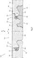
- first connection profiles 104 and second connection profiles 105 are included, which comprise on opposite short narrow sides 102,103 first connection profiles 104 and second connection profiles 105.
- the first and second connection profiles 104,105 are formed corresponding to each other so that they can be connected by Ein winking into each other.
- the first connection profile 104 is thereby inclined and plugged into the second connection profile 105.
- the first connection profile 104 is pivoted down about the inserted narrow side 102 down. It comes to a locking of the first and second connection profiles 104,105 in a vertical and a horizontal direction V, H.
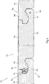
- third and fourth connection profiles 108,109 are provided at the two long narrow sides 106,107 of the standard panels 101, which in the Fig. 4 are shown.
- the third and fourth connection profiles 108, 109 of the standard panels can also be connected to one another in the manner described above by being angled.
- the replacement panel 110 of the in Fig. 3 and 4 illustrated system comprises a connecting element 112, which in the Fig. 5 is shown in detail, and two supplementary springs 113,114, one of which in the Fig. 6 is shown. It would also be possible if thebotpaneel if necessary as Replacement of at least one additional spring has a further connecting element.
- the connecting elements can then be mutually identical or different. In principle, no identical connecting elements should be provided on two opposite connection profiles of the replacement panel because of the different configuration of the opposing connection profiles of the standard panels.
- the provided on a short narrow side 115 of thebotpaneels 110 connecting element 112 is first connected to the first connection profile 116 of the adjacent standard panel 101.
- the standard panel 101 is slightly raised and the connecting element 112 is partially pushed under the spring 117 of the first connection profile 116 of the standard panel 101.
- the spring 117 of the first connecting profile 116 of the standard panel 101 is received in a groove 118 of the connecting element 112.
- the connecting element 112 forms a part of the first connection profile 119 of the exchange element 110, which is completed in the upper area by the panel body 120.
- a Verrieglungsprofil 121 is provided, which corresponds to a locking profile 122 of the panel body 120 is formed.
- the two locking profiles 121, 122 may be connected by a substantially vertical movement of the panel body 120 after the first connection profile 119 is connected to the standard panel 101.
- the locking profile 121 of the connecting element 112 has a locking bar 124, which extends predominantly vertically from top to bottom. Due to the substantially vertical movement of the panel body 120, the locking bar 124 of the connecting element 112 locks with the locking profile 122 of the panel body 120, in particular with a latching projection 125 of the panel body 120.
- the locking bar 124 and the panel body 120, in particular the latching projection 125 have locking surfaces 126, 127 on, which rest in the connected state in the illustrated and so far preferredstanpaneel 110 to each other.
- the locking surfaces 126,127 are significantly inclined relative to the horizontal, so that the lock not only has a force component in the vertical, but also in the horizontal direction.
- the locking bar 124 When connecting the connecting element 112 and the panel body 120, the locking bar 124 is slightly pivoted in the direction of the connecting element 112. In support of this pivoting movement of the locking bar 125 has a constriction 128 which acts in the sense of a hinge about which the locking bar 124 is pivoted. Adjacent to the locking bar 124 is a Elastizticiansnut 129 is provided which has an elastic material 130 for stabilizing the locking bar 124.
- the locking profiles 121,122 of both the panel body 120 and the connecting element 112 each have a key 131,132 and a respective passport 133,134 which are engaged with each other in the connected state.
- first mating surfaces 135,136 are provided which abut each other in the connected state and support the panel body 120 relative to the connecting element 112.
- second fitting surfaces 137,138 are provided which provide a lock in a horizontal extension direction.
- the second mating surfaces 137,138 abut each other.
- the panel body 120 has a contact surface 139, which is in contact with a corresponding contact surface 140 of the first connection profile 116 of the standard panel 101.
- the connecting element 112 in the region of the lower ends of the first connection profile 119 and the locking profile 121 stabilizing surfaces 141,142 which cooperate with corresponding stabilizing surfaces 143,144 of the first connection profile 116 of the standard panel 101 and the locking profile 122 of the panel body 120.
- the corresponding stabilizing surfaces 141, 142, 143, 144 come into contact, if necessary, with one another.
- the replacement panel 101 has, on the narrow side 146 opposite the first connection profile 119, a second connection profile 147, which is partially formed by a supplementary spring 113.
- the supplementary spring 113 is pushed into a substantially horizontally oriented groove 148 of the second connection profile 105 of the standard panel 101 prior to connection to the panel body 120.
- the supplementary spring 113 has a first, a second and a third stop surface 150,151,152, by which the supplementary spring 113 is positioned and held in the desired manner.
- the first stop surface 150 supports the supplementary spring 113 upwards against a groove flank of the groove 148 of the standard panel 101, while the second stop surface 151 supports the supplementary spring 113 down against the opposite groove flank of the groove 148.
- the third abutment surface 152 supports the supplementary spring 113 in the groove direction against the second connection profile 105 of the standard panel 101.
- the supplementary profile 113 has a locking bar 153 which extends substantially vertically from top to bottom.
- the locking bolt 153 has at its distal end on a locking surface 154 which abuts in the connected state to a corresponding locking surface 155 of a locking projection of the panel body 120 and against it supported.
- the locking bar 153 adjoins an elasticity groove 157 which is filled with an elastic material 158.
- the locking bar 153 has at the top of a constriction 159, which acts as a hinge and pivoting of the locking bolt 153 toward the adjacent standard panel 101 allows when the panel body 120 is locked by a substantially vertical movement with the supplementary spring 113.
- the illustrated and so far preferredplacepaneel 110 are provided on the provided on a long narrow side 160 of thefoundpaneels 110 third connection profile 161, no connecting element and no additional spring.
- the third connection profile 161 of the replacement panel 110 is formed exclusively by the panel body 120.
- a supplementary spring 114 is provided which is similar to the supplementary spring 113 of the second connection profile 147 and therefore will not be described again here. The same applies to the corresponding narrow sides 146, 162 of the panel body 120.
- the connection element 112 of the replacement panel 110 is connected to the first connection profile 104 of a standard panel 101.
- the standard panel 101 must be slightly raised.
- the connector 112 is then underneath pushed and takes in the groove 118, the spring 117 of the first connection profile 104 of the standard panel 101.
- the two supplementary springs 113, 134 are inserted into the grooves 148, 164 of the second and fourth connection profiles 105, 109 of two further adjacent standard panels 101.
- the third connection profile 108 of an adjacent standard panel 101 is slightly raised and the panel body 120 is angled upwards. In this angled position, the lower, projecting locking lip 165 of the third connection profile 161 of the replacement panel 110 is pushed under a part of the third connection profile 108 of the standard panel 101.
- the panel body 120 is pivoted downward from the bent position.
- This movement is understood as a substantially vertical movement of the panel body 120, which leads to a locking of the remaining narrow sides of the panel body 120.
- the locking profile 122 of the panel body 120 is locked to the locking profile 121 of the connecting element 122.
- the supplementary springs 113,114 of the second and the fourth connection profile 147,163 are locked to the panel body.
- the panel body 120, and thus the replacement panel 110 are themselves locked to the standard panels 101 adjacent to the previous gap of the floor covering 100.
- the panel body 120 abuts peripherally with an upper section on the circulating standard panels 101.
Claims (17)
- Système (1, 170) de formation d'un revêtement de sol à pose flottante (2, 100),- avec une multitude de panneaux standard similaires (6, 101) et au moins un panneau de remplacement (3, 110) pour le remplacement d'un panneau standard,- où les panneaux standard (6, 101) présentent, respectivement sur au moins deux côtés étroits opposés (7, 8, 102, 103), un premier et un deuxième profil de raccordement (9, 10, 104, 105) pouvant être reliés ensemble et formés de manière à se correspondre, et- où le panneau de remplacement (3, 110) présente un premier profil de raccordement (13, 116) formé de manière correspondante et pouvant être relié au premier profil de raccordement (9, 104) d'un panneau standard (6, 101),caractérisé en ce que- le panneau de remplacement (3, 110) se différencie du panneau standard (6, 101) et comporte au moins un corps de panneau (11, 120) et au moins un élément de raccordement (12, 112),- le premier profil de raccordement (13, 119) du panneau de remplacement (3, 110) est formé, au moins partiellement, par l'élément de raccordement (12, 112) et- l'élément de raccordement (12, 112) et le corps de panneau (11, 120) présentent des profils de verrouillage (33, 34, 121, 122) correspondants pouvant être verrouillés ensemble mécaniquement par un mouvement essentiellement vertical du corps de panneau (11, 120).
- Système selon la revendication 1, caractérisé en ce que les premiers profils de raccordement (9, 13, 104, 116) sont formés, de sorte à pouvoir être verrouillés ensemble, par le panneau de remplacement (3, 110) et le panneau standard (6, 101) dans une direction verticales (V) et dans une direction horizontale (H), perpendiculairement par rapport aux premiers profils de raccordement (9, 13, 104, 106).
- Système selon la revendication 1 ou 2, caractérisé en ce que les profils de verrouillage (33, 34, 121, 122) de l'élément de raccordement (12, 112) et du corps de panneau (11, 120) sont formés de sorte à pouvoir être verrouillés ensemble dans une direction verticale (V) et dans une direction horizontale (H), perpendiculairement par rapport aux profils de verrouillage (33, 34, 121, 122).
- Système selon l'une des revendications de 1 à 3, caractérisé en ce que l'élément de raccordement (12, 112) présente un verrou de blocage (35, 124) destiné à former une liaison d'encliquetage avec le corps de panneau (11, 120), de préférence essentiellement dans une direction verticale (V).
- Système selon l'une des revendications de 1 à 4, caractérisé en ce que- le profil de verrouillage (33, 34, 121, 122) de l'élément de raccordement (12, 112) et du corps de panneau (11, 120) présente deux premières surfaces d'ajustement (46, 47, 135, 136) coopérantes dans un état assemblé et- les premières surfaces d'ajustement (46, 47, 135, 136) sont formées de telle sorte que, dans l'état assemblé du corps de panneau (11, 120), la première surface d'ajustement (46, 135) repose sur la première surface d'ajustement (47, 136) de l'élément de raccordement (12, 112).
- Système selon la revendication 5, caractérisé en ce que- la première surface d'ajustement (46, 47, 135, 136) de l'élément de raccordement (12, 112) ou du corps de panneau (11, 120) est prévue sur un fond de rainure d'une gorge de montage (51, 133) orientée essentiellement à la verticale et- la première surface d'ajustement (46, 47, 135, 136) du corps de panneau (11, 120) ou de l'élément de raccordement (12, 112) est prévue sur une clavette (48, 131) orientée essentiellement à la verticale.
- Système selon l'une des revendications de 1 à 6, caractérisé en ce que- l'élément de raccordement (12, 112) et le corps de panneau (11, 120) présentent deux deuxièmes surfaces d'ajustement (49, 50, 137, 138) et- les deuxièmes surfaces d'ajustement (49, 50, 137, 138) sont formées de telle sorte que les deuxièmes surfaces d'ajustement (49, 50, 137, 138), à l'état assemblé, provoquent un verrouillage dans une direction d'extraction horizontale, perpendiculairement par rapport aux profils de verrouillage (33, 34, 121, 122).
- Système selon la revendication 7, caractérisé en ce que l'on prévoit la deuxième surface d'ajustement (49, 50, 137, 138) de l'élément de raccordement (12, 112) ou du corps de panneau (11, 120) sur un flanc de rainure, de préférence intérieur, de la gorge de montage (51, 133) ou du flanc de ressort de la clavette (48, 131).
- Système selon l'une des revendications de 1 à 8, caractérisé en ce que- le panneau de remplacement (110) présente un deuxième profil de raccordement (147) correspondant au deuxième profil de raccordement (105) d'un panneau standard (101),- le deuxième profil de raccordement (147) du panneau de remplacement (110) est formé partiellement par un ressort complémentaire (113) séparé du panneau de remplacement (110) et- le ressort complémentaire (113) et le corps de panneau (120) sont formés de sorte à relier le deuxième profil de raccordement (147) du panneau de remplacement (110) au deuxième profil de raccordement (105) d'un panneau standard adjacent (101) par un mouvement essentiellement vertical du corps de panneau (120).
- Système selon la revendication 9, caractérisé en ce que le ressort complémentaire (113) présente un verrou de blocage (124) destiné à former une liaison d'encliquetage avec le corps de panneau (120), de préférence essentiellement en direction verticale.
- Système selon l'une des revendications de 4 à 10, caractérisé en ce que l'on prévoit adjacent au verrou de blocage (35, 124, 153) de l'élément de raccordement (12, 112) et/ou du ressort complémentaire (113) une rainure élastique (43, 129, 157), de préférence remplie d'un matériau élastique (130, 158).
- Système selon l'une des revendications de 4 à 11, caractérisé en ce que le verrou de blocage (124, 153) de l'élément de raccordement (112) et/ou du ressort complémentaire (113) présente un rétrécissement (128, 159) formant une charnière.
- Système selon l'une des revendications de 9 à 12, caractérisé en ce que le ressort complémentaire (113) présente, de préférence, respectivement au moins une surface de butée (150, 151, 152) soutenant le ressort complémentaire (113) par rapport au deuxième profil de raccordement (105) du panneau standard (101) en direction verticale et horizontale (V, H).
- Système selon l'une des revendications de 1 à 13, caractérisé en ce que- les panneaux standard présentent, respectivement sur deux autres côtés étroits opposés, un troisième et un quatrième profil de raccordement formés de manière à se correspondre,- où le panneau de remplacement présente un troisième profil de raccordement formé de manière correspondante au troisième profil de raccordement d'un panneau standard,- où le panneau de remplacement comporte un deuxième élément de raccordement formant au moins partiellement le troisième profil de raccordement,- où le deuxième élément de raccordement et le corps de panneau présentent des profils de raccordement correspondants pouvant être verrouillés ensemble mécaniquement par un mouvement essentiellement vertical du corps de panneau.
- Revêtement de sol (2, 100) à pose flottante avec au moins un panneau de remplacement (3, 110), caractérisé en ce que le revêtement de sol (2, 100) comporte un système (1, 170) selon au moins une des revendications 1 à 14.
- Procédé de remplacement d'au moins un panneau standard (6, 101) d'un revêtement de sol à pose flottante (2, 100) par au moins un panneau de remplacement (3, 110) étant différent du panneau standard- où les panneaux standard (6, 101) présentent, respectivement sur des côtés étroits opposés (7, 8, 102, 103), un premier et un deuxième profil de raccordement (9, 10, 104, 105) pouvant être reliés ensemble et formés de manière à se correspondre et- où le panneau de remplacement (3, 110) comporte au moins un corps de panneau (11, 120) et au moins un élément de raccordement (12, 112),- lors duquel au moins un panneau standard (6, 101) est extrait de l'ensemble du revêtement du sol (2, 100),caractérisé en ce que- le premier profil de raccordement (9, 104) d'un panneau standard (6, 101) adjacent initialement au panneau standard prélevé est relié à l'élément de raccordement (12, 112) du panneau de remplacement (3, 110) et- le corps de panneau (11, 120) est par la suite verrouillé mécaniquement avec l'élément de raccordement (12, 112) dans un mouvement essentiellement vertical du corps de panneau (11, 120).
- Procédé selon la revendication 16,- lors duquel le panneau de remplacement (101) présente au moins un ressort complémentaire (113),- lors duquel le ressort complémentaire (113) est inséré dans une rainure (148) du deuxième profil de raccordement (105) d'un autre panneau standard (101) adjacent initialement au panneau standard (101) prélevé et- lors duquel le deuxième profil de raccordement (147) du panneau de remplacement (110) est verrouillé mécaniquement, par un mouvement essentiellement vertical du corps de panneau (120), avec le deuxième profil de raccordement (105) de l'autre panneau standard (101) adjacent initialement au panneau standard (101) prélevé.
Priority Applications (1)
| Application Number | Priority Date | Filing Date | Title |
|---|---|---|---|
| PL11168873T PL2397624T3 (pl) | 2010-06-16 | 2011-06-07 | Układ i sposób ukształtowania pokrycia podłogi ze standardowych paneli i co najmniej jednego panelu wymiennego |
Applications Claiming Priority (1)
| Application Number | Priority Date | Filing Date | Title |
|---|---|---|---|
| DE102010023922.4A DE102010023922B4 (de) | 2010-06-16 | 2010-06-16 | System und Verfahren zur Bildung eines Fußbodenbelags aus Standardpaneelen und wenigstens einem Austauschpaneel |
Publications (3)
| Publication Number | Publication Date |
|---|---|
| EP2397624A2 EP2397624A2 (fr) | 2011-12-21 |
| EP2397624A3 EP2397624A3 (fr) | 2013-07-24 |
| EP2397624B1 true EP2397624B1 (fr) | 2017-11-15 |
Family
ID=44118284
Family Applications (1)
| Application Number | Title | Priority Date | Filing Date |
|---|---|---|---|
| EP11168873.5A Active EP2397624B1 (fr) | 2010-06-16 | 2011-06-07 | Système et procédé de formation d'un revêtement de sol en panneaux standard et au moins un panneau de remplacement |
Country Status (4)
| Country | Link |
|---|---|
| EP (1) | EP2397624B1 (fr) |
| DE (1) | DE102010023922B4 (fr) |
| ES (1) | ES2658308T3 (fr) |
| PL (1) | PL2397624T3 (fr) |
Families Citing this family (5)
| Publication number | Priority date | Publication date | Assignee | Title |
|---|---|---|---|---|
| BE1019331A5 (nl) | 2010-05-10 | 2012-06-05 | Flooring Ind Ltd Sarl | Vloerpaneel en werkwijzen voor het vervaardigen van vloerpanelen. |
| US8806832B2 (en) | 2011-03-18 | 2014-08-19 | Inotec Global Limited | Vertical joint system and associated surface covering system |
| CN106522495B (zh) * | 2016-12-15 | 2017-10-20 | 俞昱 | 一种新型组合墙板 |
| EP3807475B1 (fr) * | 2018-06-13 | 2023-11-15 | Ceraloc Innovation AB | Système de revêtement de plancher doté d'un système d'assemblage et dispositif d'assemblage associé |
| WO2021167521A1 (fr) * | 2020-02-20 | 2021-08-26 | Välinge Innovation AB | Agencements pour le remplacement d'un panneau de construction |
Citations (2)
| Publication number | Priority date | Publication date | Assignee | Title |
|---|---|---|---|---|
| JP2000320109A (ja) * | 1999-05-11 | 2000-11-21 | Nippon Steel Chem Co Ltd | 補修用床材及び直貼り床板の補修方法 |
| WO2001066877A1 (fr) * | 2000-03-10 | 2001-09-13 | Perstorp Flooring Ab | Elements de plancher assembles verticalement et comprenant une combinaison d'elements differents |
Family Cites Families (8)
| Publication number | Priority date | Publication date | Assignee | Title |
|---|---|---|---|---|
| DE20013453U1 (de) | 1999-09-27 | 2001-02-22 | Purnot Klaus | Reparaturset für Laminat- und Parkett Boden |
| BE1013569A3 (nl) | 2000-06-20 | 2002-04-02 | Unilin Beheer Bv | Vloerbekleding. |
| ES2609056T3 (es) | 2002-04-03 | 2017-04-18 | Välinge Innovation AB | Método de fijación de una tira a una placa de tarima flotante |
| DE10231921A1 (de) | 2002-06-28 | 2004-01-22 | E.F.P. Floor Products Fussböden GmbH | Paneel eines Fußbodensystems, insbesondere eines Laminatfußbodens |
| SE529664C2 (sv) | 2005-07-11 | 2007-10-16 | Pergo Europ Ab | En fogprofil till en panel |
| DE102007019786B4 (de) | 2006-12-22 | 2013-05-08 | Hamberger Industriewerke Gmbh | Verbindung für plattenförmige Bauelemente |
| DE202007000310U1 (de) | 2007-01-03 | 2007-04-19 | Akzenta Paneele + Profile Gmbh | Paneel sowie Bodenbelag |
| US8037656B2 (en) * | 2008-08-08 | 2011-10-18 | Liu David C | Flooring boards with press down locking mechanism |
-
2010
- 2010-06-16 DE DE102010023922.4A patent/DE102010023922B4/de active Active
-
2011
- 2011-06-07 EP EP11168873.5A patent/EP2397624B1/fr active Active
- 2011-06-07 ES ES11168873.5T patent/ES2658308T3/es active Active
- 2011-06-07 PL PL11168873T patent/PL2397624T3/pl unknown
Patent Citations (2)
| Publication number | Priority date | Publication date | Assignee | Title |
|---|---|---|---|---|
| JP2000320109A (ja) * | 1999-05-11 | 2000-11-21 | Nippon Steel Chem Co Ltd | 補修用床材及び直貼り床板の補修方法 |
| WO2001066877A1 (fr) * | 2000-03-10 | 2001-09-13 | Perstorp Flooring Ab | Elements de plancher assembles verticalement et comprenant une combinaison d'elements differents |
Also Published As
| Publication number | Publication date |
|---|---|
| EP2397624A3 (fr) | 2013-07-24 |
| DE102010023922A1 (de) | 2011-12-22 |
| DE102010023922B4 (de) | 2022-07-28 |
| ES2658308T3 (es) | 2018-03-09 |
| EP2397624A2 (fr) | 2011-12-21 |
| PL2397624T3 (pl) | 2018-04-30 |
Similar Documents
| Publication | Publication Date | Title |
|---|---|---|
| DE10206877B4 (de) | Paneel, insbesondere Fussbodenpaneel | |
| EP1246981B1 (fr) | Panneaux | |
| EP1200690B2 (fr) | Procede pour poser et bloquer des panneaux | |
| EP2057327B1 (fr) | Panneau, notamment panneau de sol | |
| AT410815B (de) | Verbindung von plattenförmigen bauteilen | |
| DE102006057491A1 (de) | Paneel sowie Bodenbelag | |
| DE202007018662U1 (de) | Paneel, insbesondere Bodenpaneel | |
| EP1400641A2 (fr) | Panneaux avec clip de fixation | |
| WO2005083195A1 (fr) | Dispositif de recouvrement pour revêtements de sol | |
| DE10159284A1 (de) | Gebäudeplatte, insbesondere Bodenpaneel | |
| DE202007000310U1 (de) | Paneel sowie Bodenbelag | |
| WO2006133690A1 (fr) | Panneau pour plancher possedant une partie centrale en materiau derive du bois, une couche de decoration et des profils de verrouillage | |
| DE102007002590A1 (de) | Paneel sowie Bodenbelag | |
| DE20319121U1 (de) | Paneel, insbesondere Fußbodenpaneel | |
| EP2397624B1 (fr) | Système et procédé de formation d'un revêtement de sol en panneaux standard et au moins un panneau de remplacement | |
| WO2018108206A1 (fr) | Système de connexion pour la connexion de deux châssis d'armoire électrique | |
| EP2404012B1 (fr) | Panneau destiné à former un revêtement et procédé de fabrication d'un tel revêtement | |
| DE102005061645B4 (de) | Bodenbelag mit an beliebiger Stelle aus dem Verbund entfernbaren Paneelen | |
| WO2009006926A1 (fr) | CONCEPT DE PANNEAU DE PAROI À 45º | |
| EP3420158B1 (fr) | Système pour encliqueter deux panneaux de sol | |
| DE102008003117A1 (de) | Einrichtung zum Verriegeln zweier Bauplatten | |
| EP3037681B1 (fr) | Systeme de separation d'espace avec un dispositif de liaison et une un profile creux | |
| EP1416103A1 (fr) | Revêtement de sol comprenant des panneaux assemblables | |
| DE102017110878A1 (de) | Einrichtung zum Verriegeln zweier Bodenpaneele | |
| DE202009011997U1 (de) | Paneel zur Bildung eines Belags |
Legal Events
| Date | Code | Title | Description |
|---|---|---|---|
| AK | Designated contracting states |
Kind code of ref document: A2 Designated state(s): AL AT BE BG CH CY CZ DE DK EE ES FI FR GB GR HR HU IE IS IT LI LT LU LV MC MK MT NL NO PL PT RO RS SE SI SK SM TR |
|
| AX | Request for extension of the european patent |
Extension state: BA ME |
|
| PUAI | Public reference made under article 153(3) epc to a published international application that has entered the european phase |
Free format text: ORIGINAL CODE: 0009012 |
|
| PUAL | Search report despatched |
Free format text: ORIGINAL CODE: 0009013 |
|
| AK | Designated contracting states |
Kind code of ref document: A3 Designated state(s): AL AT BE BG CH CY CZ DE DK EE ES FI FR GB GR HR HU IE IS IT LI LT LU LV MC MK MT NL NO PL PT RO RS SE SI SK SM TR |
|
| AX | Request for extension of the european patent |
Extension state: BA ME |
|
| RIC1 | Information provided on ipc code assigned before grant |
Ipc: E04F 15/02 20060101AFI20130619BHEP |
|
| 17P | Request for examination filed |
Effective date: 20140123 |
|
| RBV | Designated contracting states (corrected) |
Designated state(s): AL AT BE BG CH CY CZ DE DK EE ES FI FR GB GR HR HU IE IS IT LI LT LU LV MC MK MT NL NO PL PT RO RS SE SI SK SM TR |
|
| RAP1 | Party data changed (applicant data changed or rights of an application transferred) |
Owner name: FRITZ EGGER GMBH & CO. OG |
|
| 17Q | First examination report despatched |
Effective date: 20160622 |
|
| GRAP | Despatch of communication of intention to grant a patent |
Free format text: ORIGINAL CODE: EPIDOSNIGR1 |
|
| RIC1 | Information provided on ipc code assigned before grant |
Ipc: E04G 23/02 20060101ALN20170331BHEP Ipc: E04F 15/02 20060101AFI20170331BHEP |
|
| GRAJ | Information related to disapproval of communication of intention to grant by the applicant or resumption of examination proceedings by the epo deleted |
Free format text: ORIGINAL CODE: EPIDOSDIGR1 |
|
| INTG | Intention to grant announced |
Effective date: 20170428 |
|
| INTC | Intention to grant announced (deleted) | ||
| GRAP | Despatch of communication of intention to grant a patent |
Free format text: ORIGINAL CODE: EPIDOSNIGR1 |
|
| RIC1 | Information provided on ipc code assigned before grant |
Ipc: E04F 15/02 20060101AFI20170607BHEP Ipc: E04G 23/02 20060101ALN20170607BHEP |
|
| INTG | Intention to grant announced |
Effective date: 20170713 |
|
| GRAS | Grant fee paid |
Free format text: ORIGINAL CODE: EPIDOSNIGR3 |
|
| GRAA | (expected) grant |
Free format text: ORIGINAL CODE: 0009210 |
|
| AK | Designated contracting states |
Kind code of ref document: B1 Designated state(s): AL AT BE BG CH CY CZ DE DK EE ES FI FR GB GR HR HU IE IS IT LI LT LU LV MC MK MT NL NO PL PT RO RS SE SI SK SM TR |
|
| REG | Reference to a national code |
Ref country code: CH Ref legal event code: EP Ref country code: GB Ref legal event code: FG4D Free format text: NOT ENGLISH Ref country code: AT Ref legal event code: REF Ref document number: 946434 Country of ref document: AT Kind code of ref document: T Effective date: 20171115 |
|
| REG | Reference to a national code |
Ref country code: IE Ref legal event code: FG4D Free format text: LANGUAGE OF EP DOCUMENT: GERMAN |
|
| REG | Reference to a national code |
Ref country code: DE Ref legal event code: R096 Ref document number: 502011013283 Country of ref document: DE |
|
| REG | Reference to a national code |
Ref country code: CH Ref legal event code: NV Representative=s name: SCHMAUDER AND PARTNER AG PATENT- UND MARKENANW, CH |
|
| REG | Reference to a national code |
Ref country code: RO Ref legal event code: EPE |
|
| REG | Reference to a national code |
Ref country code: SE Ref legal event code: TRGR |
|
| REG | Reference to a national code |
Ref country code: NL Ref legal event code: FP |
|
| REG | Reference to a national code |
Ref country code: ES Ref legal event code: FG2A Ref document number: 2658308 Country of ref document: ES Kind code of ref document: T3 Effective date: 20180309 |
|
| REG | Reference to a national code |
Ref country code: LT Ref legal event code: MG4D |
|
| PG25 | Lapsed in a contracting state [announced via postgrant information from national office to epo] |
Ref country code: FI Free format text: LAPSE BECAUSE OF FAILURE TO SUBMIT A TRANSLATION OF THE DESCRIPTION OR TO PAY THE FEE WITHIN THE PRESCRIBED TIME-LIMIT Effective date: 20171115 Ref country code: NO Free format text: LAPSE BECAUSE OF FAILURE TO SUBMIT A TRANSLATION OF THE DESCRIPTION OR TO PAY THE FEE WITHIN THE PRESCRIBED TIME-LIMIT Effective date: 20180215 Ref country code: LT Free format text: LAPSE BECAUSE OF FAILURE TO SUBMIT A TRANSLATION OF THE DESCRIPTION OR TO PAY THE FEE WITHIN THE PRESCRIBED TIME-LIMIT Effective date: 20171115 |
|
| PG25 | Lapsed in a contracting state [announced via postgrant information from national office to epo] |
Ref country code: HR Free format text: LAPSE BECAUSE OF FAILURE TO SUBMIT A TRANSLATION OF THE DESCRIPTION OR TO PAY THE FEE WITHIN THE PRESCRIBED TIME-LIMIT Effective date: 20171115 Ref country code: RS Free format text: LAPSE BECAUSE OF FAILURE TO SUBMIT A TRANSLATION OF THE DESCRIPTION OR TO PAY THE FEE WITHIN THE PRESCRIBED TIME-LIMIT Effective date: 20171115 Ref country code: GR Free format text: LAPSE BECAUSE OF FAILURE TO SUBMIT A TRANSLATION OF THE DESCRIPTION OR TO PAY THE FEE WITHIN THE PRESCRIBED TIME-LIMIT Effective date: 20180216 Ref country code: BG Free format text: LAPSE BECAUSE OF FAILURE TO SUBMIT A TRANSLATION OF THE DESCRIPTION OR TO PAY THE FEE WITHIN THE PRESCRIBED TIME-LIMIT Effective date: 20180215 |
|
| REG | Reference to a national code |
Ref country code: FR Ref legal event code: PLFP Year of fee payment: 8 |
|
| PG25 | Lapsed in a contracting state [announced via postgrant information from national office to epo] |
Ref country code: CY Free format text: LAPSE BECAUSE OF FAILURE TO SUBMIT A TRANSLATION OF THE DESCRIPTION OR TO PAY THE FEE WITHIN THE PRESCRIBED TIME-LIMIT Effective date: 20171115 Ref country code: EE Free format text: LAPSE BECAUSE OF FAILURE TO SUBMIT A TRANSLATION OF THE DESCRIPTION OR TO PAY THE FEE WITHIN THE PRESCRIBED TIME-LIMIT Effective date: 20171115 Ref country code: SK Free format text: LAPSE BECAUSE OF FAILURE TO SUBMIT A TRANSLATION OF THE DESCRIPTION OR TO PAY THE FEE WITHIN THE PRESCRIBED TIME-LIMIT Effective date: 20171115 Ref country code: DK Free format text: LAPSE BECAUSE OF FAILURE TO SUBMIT A TRANSLATION OF THE DESCRIPTION OR TO PAY THE FEE WITHIN THE PRESCRIBED TIME-LIMIT Effective date: 20171115 |
|
| REG | Reference to a national code |
Ref country code: DE Ref legal event code: R097 Ref document number: 502011013283 Country of ref document: DE |
|
| PG25 | Lapsed in a contracting state [announced via postgrant information from national office to epo] |
Ref country code: SM Free format text: LAPSE BECAUSE OF FAILURE TO SUBMIT A TRANSLATION OF THE DESCRIPTION OR TO PAY THE FEE WITHIN THE PRESCRIBED TIME-LIMIT Effective date: 20171115 |
|
| PLBE | No opposition filed within time limit |
Free format text: ORIGINAL CODE: 0009261 |
|
| STAA | Information on the status of an ep patent application or granted ep patent |
Free format text: STATUS: NO OPPOSITION FILED WITHIN TIME LIMIT |
|
| PG25 | Lapsed in a contracting state [announced via postgrant information from national office to epo] |
Ref country code: MT Free format text: LAPSE BECAUSE OF FAILURE TO SUBMIT A TRANSLATION OF THE DESCRIPTION OR TO PAY THE FEE WITHIN THE PRESCRIBED TIME-LIMIT Effective date: 20171115 |
|
| 26N | No opposition filed |
Effective date: 20180817 |
|
| PG25 | Lapsed in a contracting state [announced via postgrant information from national office to epo] |
Ref country code: SI Free format text: LAPSE BECAUSE OF FAILURE TO SUBMIT A TRANSLATION OF THE DESCRIPTION OR TO PAY THE FEE WITHIN THE PRESCRIBED TIME-LIMIT Effective date: 20171115 |
|
| REG | Reference to a national code |
Ref country code: IE Ref legal event code: MM4A |
|
| PG25 | Lapsed in a contracting state [announced via postgrant information from national office to epo] |
Ref country code: LU Free format text: LAPSE BECAUSE OF NON-PAYMENT OF DUE FEES Effective date: 20180607 Ref country code: MC Free format text: LAPSE BECAUSE OF FAILURE TO SUBMIT A TRANSLATION OF THE DESCRIPTION OR TO PAY THE FEE WITHIN THE PRESCRIBED TIME-LIMIT Effective date: 20171115 |
|
| PG25 | Lapsed in a contracting state [announced via postgrant information from national office to epo] |
Ref country code: IE Free format text: LAPSE BECAUSE OF NON-PAYMENT OF DUE FEES Effective date: 20180607 |
|
| PG25 | Lapsed in a contracting state [announced via postgrant information from national office to epo] |
Ref country code: PT Free format text: LAPSE BECAUSE OF FAILURE TO SUBMIT A TRANSLATION OF THE DESCRIPTION OR TO PAY THE FEE WITHIN THE PRESCRIBED TIME-LIMIT Effective date: 20171115 Ref country code: HU Free format text: LAPSE BECAUSE OF FAILURE TO SUBMIT A TRANSLATION OF THE DESCRIPTION OR TO PAY THE FEE WITHIN THE PRESCRIBED TIME-LIMIT; INVALID AB INITIO Effective date: 20110607 |
|
| PG25 | Lapsed in a contracting state [announced via postgrant information from national office to epo] |
Ref country code: MK Free format text: LAPSE BECAUSE OF NON-PAYMENT OF DUE FEES Effective date: 20171115 |
|
| PG25 | Lapsed in a contracting state [announced via postgrant information from national office to epo] |
Ref country code: AL Free format text: LAPSE BECAUSE OF FAILURE TO SUBMIT A TRANSLATION OF THE DESCRIPTION OR TO PAY THE FEE WITHIN THE PRESCRIBED TIME-LIMIT Effective date: 20171115 Ref country code: IS Free format text: LAPSE BECAUSE OF FAILURE TO SUBMIT A TRANSLATION OF THE DESCRIPTION OR TO PAY THE FEE WITHIN THE PRESCRIBED TIME-LIMIT Effective date: 20180315 |
|
| PGFP | Annual fee paid to national office [announced via postgrant information from national office to epo] |
Ref country code: RO Payment date: 20230531 Year of fee payment: 13 Ref country code: NL Payment date: 20230622 Year of fee payment: 13 Ref country code: FR Payment date: 20230622 Year of fee payment: 13 Ref country code: DE Payment date: 20230622 Year of fee payment: 13 Ref country code: CZ Payment date: 20230504 Year of fee payment: 13 |
|
| PGFP | Annual fee paid to national office [announced via postgrant information from national office to epo] |
Ref country code: TR Payment date: 20230503 Year of fee payment: 13 Ref country code: SE Payment date: 20230622 Year of fee payment: 13 Ref country code: PL Payment date: 20230601 Year of fee payment: 13 Ref country code: LV Payment date: 20230523 Year of fee payment: 13 Ref country code: AT Payment date: 20230623 Year of fee payment: 13 |
|
| PGFP | Annual fee paid to national office [announced via postgrant information from national office to epo] |
Ref country code: BE Payment date: 20230622 Year of fee payment: 13 |
|
| PGFP | Annual fee paid to national office [announced via postgrant information from national office to epo] |
Ref country code: IT Payment date: 20230623 Year of fee payment: 13 Ref country code: GB Payment date: 20230622 Year of fee payment: 13 Ref country code: ES Payment date: 20230726 Year of fee payment: 13 Ref country code: CH Payment date: 20230702 Year of fee payment: 13 |