EP2397231B2 - Verfahren und Vorrichtung zum Auftragen von Leim auf Zuschnittte - Google Patents
Verfahren und Vorrichtung zum Auftragen von Leim auf Zuschnittte Download PDFInfo
- Publication number
- EP2397231B2 EP2397231B2 EP11004562.2A EP11004562A EP2397231B2 EP 2397231 B2 EP2397231 B2 EP 2397231B2 EP 11004562 A EP11004562 A EP 11004562A EP 2397231 B2 EP2397231 B2 EP 2397231B2
- Authority
- EP
- European Patent Office
- Prior art keywords
- glue
- carrier
- valve
- channel
- valves
- Prior art date
- Legal status (The legal status is an assumption and is not a legal conclusion. Google has not performed a legal analysis and makes no representation as to the accuracy of the status listed.)
- Not-in-force
Links
- 239000003292 glue Substances 0.000 title claims description 188
- 238000004026 adhesive bonding Methods 0.000 claims description 8
- 239000012876 carrier material Substances 0.000 claims description 7
- 238000007789 sealing Methods 0.000 claims description 5
- 230000000903 blocking effect Effects 0.000 claims 3
- 230000000694 effects Effects 0.000 claims 3
- 230000000295 complement effect Effects 0.000 claims 1
- 230000037431 insertion Effects 0.000 claims 1
- 238000003780 insertion Methods 0.000 claims 1
- 238000007493 shaping process Methods 0.000 claims 1
- 238000009826 distribution Methods 0.000 description 16
- 230000005540 biological transmission Effects 0.000 description 2
- 235000019504 cigarettes Nutrition 0.000 description 2
- 238000010276 construction Methods 0.000 description 2
- 230000006735 deficit Effects 0.000 description 2
- 238000004519 manufacturing process Methods 0.000 description 2
- 210000000056 organ Anatomy 0.000 description 2
- HUWSZNZAROKDRZ-RRLWZMAJSA-N (3r,4r)-3-azaniumyl-5-[[(2s,3r)-1-[(2s)-2,3-dicarboxypyrrolidin-1-yl]-3-methyl-1-oxopentan-2-yl]amino]-5-oxo-4-sulfanylpentane-1-sulfonate Chemical compound OS(=O)(=O)CC[C@@H](N)[C@@H](S)C(=O)N[C@@H]([C@H](C)CC)C(=O)N1CCC(C(O)=O)[C@H]1C(O)=O HUWSZNZAROKDRZ-RRLWZMAJSA-N 0.000 description 1
- 230000015572 biosynthetic process Effects 0.000 description 1
- 238000006243 chemical reaction Methods 0.000 description 1
- 238000009434 installation Methods 0.000 description 1
- 239000000463 material Substances 0.000 description 1
- 238000012986 modification Methods 0.000 description 1
- 230000004048 modification Effects 0.000 description 1
- 238000004806 packaging method and process Methods 0.000 description 1
- 238000004382 potting Methods 0.000 description 1
- 238000009420 retrofitting Methods 0.000 description 1
- 239000000758 substrate Substances 0.000 description 1
- 239000013589 supplement Substances 0.000 description 1
- 230000007704 transition Effects 0.000 description 1
- 230000001960 triggered effect Effects 0.000 description 1
Images


Classifications
-
- B—PERFORMING OPERATIONS; TRANSPORTING
- B05—SPRAYING OR ATOMISING IN GENERAL; APPLYING FLUENT MATERIALS TO SURFACES, IN GENERAL
- B05C—APPARATUS FOR APPLYING FLUENT MATERIALS TO SURFACES, IN GENERAL
- B05C5/00—Apparatus in which liquid or other fluent material is projected, poured or allowed to flow on to the surface of the work
- B05C5/02—Apparatus in which liquid or other fluent material is projected, poured or allowed to flow on to the surface of the work the liquid or other fluent material being discharged through an outlet orifice by pressure, e.g. from an outlet device in contact or almost in contact, with the work
- B05C5/027—Coating heads with several outlets, e.g. aligned transversally to the moving direction of a web to be coated
- B05C5/0275—Coating heads with several outlets, e.g. aligned transversally to the moving direction of a web to be coated flow controlled, e.g. by a valve
- B05C5/0279—Coating heads with several outlets, e.g. aligned transversally to the moving direction of a web to be coated flow controlled, e.g. by a valve independently, e.g. individually, flow controlled
-
- B—PERFORMING OPERATIONS; TRANSPORTING
- B05—SPRAYING OR ATOMISING IN GENERAL; APPLYING FLUENT MATERIALS TO SURFACES, IN GENERAL
- B05C—APPARATUS FOR APPLYING FLUENT MATERIALS TO SURFACES, IN GENERAL
- B05C5/00—Apparatus in which liquid or other fluent material is projected, poured or allowed to flow on to the surface of the work
- B05C5/02—Apparatus in which liquid or other fluent material is projected, poured or allowed to flow on to the surface of the work the liquid or other fluent material being discharged through an outlet orifice by pressure, e.g. from an outlet device in contact or almost in contact, with the work
- B05C5/0291—Apparatus in which liquid or other fluent material is projected, poured or allowed to flow on to the surface of the work the liquid or other fluent material being discharged through an outlet orifice by pressure, e.g. from an outlet device in contact or almost in contact, with the work the material being discharged on the work through discrete orifices as discrete droplets, beads or strips that coalesce on the work or are spread on the work so as to form a continuous coating
Definitions
- the invention relates to a device for applying glue to carrier material having the features of the preambles of claims 1, 2, 3.
- glue unit is positioned stationary and the carrier material, in particular the blanks are moved past the glue unit, which are guaranteed due to precise control of metering, in particular of closure organs of Leimventile the exact delivery of Leimportionen and positionally accurate transfer to the substrate.
- the invention is intended to open up the possibility of being able to produce different glue images with a device having a plurality of glue outlets, in particular several glue valves, in accordance with the requirement due to the different design of blanks for packs.
- the invention has for its object to form a device for applying glue or a glue unit so that in a simple manner, a conversion can be done to produce different glue images on carrier material, in particular on blanks.
- a special feature of the invention is that a (not used because of Leimsentes) glue valve removed from the glue unit and replaced by a replacement piece or auxiliary piece, due to the design and arrangement of a particular common for all glue valves glue channel or distribution channel in the area the connection to the removed valve shuts off.
- the replacement piece / auxiliary piece is designed so that it - when arranged in the region of the removed glue valve - serves as a carrier for further functional means of the glue valve.
- a preferably leading to each glue valve electrical control line is positioned with end contact on the replacement piece / auxiliary piece, in particular fixed, without significant change in the relative position.
- An innovation relates to the structural design of the glue unit with the aim of easy assembly and removability of single or all glue valves. These are arranged on a preferably common carrier with a rail-like cross-sectional profile, in particular on the underside of the carrier positioned side by side and fastened by simple connection means, in particular by (two) screws. If a glue valve is removed, the replacement piece can be positioned in the same place and fixed with the same or the same connection means.
- a glue unit - is used for example for the transmission of glue portions or glue 10 on individual blanks 11 for the production of packages, especially folding boxes for cigarettes.
- glue points 10 there are several juxtaposed glue points 10 to be transferred to each blank 11.
- a complex glue picture ( EP 0 601 411 A2 ) consists of several adjacent rows of dots 12 per blank 11.
- each individual glue points 10 are shown by several adjacent rows of points 12 extending transversely to the plane of the drawing.
- the glue unit comprises a plurality of glue dispensers, in the present case glue valves 13.
- glue valves 13 are juxtaposed and mounted on a common carrier 14.
- the glue valves 13 are positioned so that the glue portions emitted by a valve nozzle 15, namely glue spots 10, exactly on the blank 11 are positioned.
- the glue valve 13 may, for example, substantially according to DE 10 2009 022 496.3 be formed, but with important modifications that facilitate the assembly and removal of the glue valve.
- the arrangement is such that the glue unit is positioned in a stationary manner with a plurality of glue valves 13 arranged next to one another above a movement or conveying path for the blanks 11.
- the blanks 11 transported at a short distance below the glue valves are provided with the respectively required glue pattern consisting of several rows of dots 12 by briefly opening the glue valves 13.
- the structure of the glue unit is chosen in this example so that the transverse support 14 is fixed in the glue station (a packaging machine) with connecting means, here with end flanges 16, to the construction of the machine.
- the glue unit according to Fig. 1 is geared towards two-lane operation. Accordingly, two groups of glue valves 13 are mounted on a common carrier 14, with two adjacent blanks 11 each being transported below the gluing unit (thus formed in a horizontal plane).
- the (six) glue valves 13 of the two working paths are with a to f on the one hand and g to I on the other hand in Fig. 1 characterized.
- glue valves of the glue unit are supplied with glue via a common glue line.
- this is designed as (transverse to the direction of movement of the blanks 11) extending distribution channel 17, preferably in the embodiment as a through hole in the carrier 14 with a suitable (circular) cross-section.
- the distribution channel 17, the glue via a central line (under pressure) is supplied.
- This is preferably connected centrally between the two groups of glue valves 13 with the distribution channel 17.
- the central line 18 connects to a central (upright) support piece 19, which is arranged between the two groups of glue valves 13 and connected to the carrier 14.
- a channel (or conduit) is arranged to connect the mouth of the central conduit 18 to the distribution channel 17.
- the distribution channel 17 is functionally composed of two sections which are supplied together with glue by the central line 18. Depending on a portion of the distribution channel 17 leads to the one and to the other group of glue valves 13 on the carrier 14.
- the (transverse) profile of the carrier 14 is formed so that a sufficiently sized distribution channel recording. For this purpose, an approximately square channel profile 20 (edge) on the carrier 14 is formed. In this runs the distribution channel 17, such that all glue valves 13 can be supplied with glue.
- the channel profile 20 is connected to a flat profile or a support flange 21 of the carrier 14 to form a uniform profile.
- the glue valves 13 are individually detachably connected to the support 14 in the region of the support flange 21.
- the glue valves 13 are arranged on the underside of the carrier 14 and fastened by screws 22, in the present case by two screws 22 to the carrier 14.
- the distribution channel 17 is connected to each glue valve 13 via at least one glue connection.
- a branch channel 23 is provided, which preferably leads as a bore from the distributor channel 17 to the glue valve 13 and adjoins an (upright) glue channel 24 within the glue valve 13.
- the glue valve 13 is positioned and the branch channel 23 is mounted so that the branch channel 23 with the glue channel 24 forms a continuous linear glue line, preferably due to matching dimensions without paragraphs or projections, so a continuous uniform channel up to a valve chamber.
- a seal is arranged, namely a sealing ring 46, which is preferably arranged on the glue valve 13, that is to say on the end region of the glue channel 24.
- the construction and operation of the glue valve correspond in principle to the glue valve DE 10 2009 022 496.3 ,
- the carrier 14 is adapted by further designs to an easy assembly and removal of the glue valves 13.
- One in the preferred used glue valves ( DE 10 2009 022 496.3 ) is arranged - approximately centrally located - on the upper side of the glue valve 13 to be operated adjusting screw 42. This occurs in the present embodiment of the carrier 14 through a recess formed in the support flange 21, which is presently designed as a threaded bore 41.
- the adjusting screw 42 is anchored with corresponding external thread in this threaded hole 41, with the possibility of adjustability of a valve member by means of this exposed adjusting screw 42nd
- FIG. 1 shows the example of the right working or the group of glue valves 13 g to I an embodiment in which two glue valves 13 - in the range of positions h and k - omitted or removed. Accordingly, fewer rows of dots 12 are transmitted accordingly.
- the position of the missing glue valve (s) 13 is supplied so that the operation for the remaining glue valves of the complete group as well as the subgroup with the glue valves g, i, j, l can continue unchanged and without impairment.
- the connection of the distribution channel 17 to the removed glue valve 13 or the glue channel 24 is to be closed first.
- a closure member is provided, preferably in the embodiment of a closure pin 25, which is inserted via the free (lower) side in the branch channel 23 and this closes.
- the closure pin 25 thus has the profile and the dimension of the branch channel 23.
- the closure pin 25 is formed so that a supplement of the cross-sectional profile of the distribution channel 24 takes place.
- the closure pin 25 is provided with a part-circular supplementary surface 26, which due to the shape and dimensions is flush with the (cylindrical) inner surface of the distribution channel 17 in the region of the branch channel 23.
- the glue can thereby be passed through the distribution channel 17 without affecting the flow.
- the closure member or the closure pin 25 is sealed against passage of material, in this case by a sealing ring 28 at the mouth of the branch channel 23rd
- the closure pin 25 is attached to a support member which is connected to the carrier 14 of the glue unit.
- the closure pin 25 is attached to a replacement piece 29, which is attached to the support 14 instead of the removed or missing glue valve 13, preferably by the same or by the same aids - screws 22 - with which the glue valve 13 is attached to the carrier 14.
- the replacement piece 29 is designed essentially as a web directed transversely to the carrier 14, at one end of which is anchored in a corresponding bore closure pin 25 is attached.
- the sealing ring 28 is arranged on the edge profile 20 facing (upper) surface.
- glue valve 13 - positions h and k in Fig. 1 - are more functional organs, which are preferably associated with each glue valve 13, temporarily or permanently secure.
- the control current is preferably supplied to the glue unit via a main line 31 common to all glue valves 13. At this close the individual control lines 30.
- the main line 31 opens into a distributor housing 32. In this connection with the individual control lines 30 is housed.
- the control line 30 passes through a passage opening 33 in a (lower) wall of the distributor housing 32 facing the glue valves 13.
- a short (upright) section of the control line 30 preferably leads in the downward direction to the associated glue valve 13.
- the control lines 30 are provided at their the glue valve 13 associated end with a connecting member, in this case with a plug 34 which is inserted into a trained for power transmission receptacle 35 in or on the housing of the glue valve 13.
- the end of the control line 30 and its plug 34 is held in the receptacle 35 by a nut 36 which is mounted on the plug 34 and cooperates with an external thread of the receptacle 35 on the glue valve 13.
- the plug receptacle 35 is due to the arrangement of the glue valve 13 and the dimension of the carrier 14 outside of the same range, so it is freely accessible by the support 14 without interference.
- the control line 30 together with the plug 34 remains substantially in the position and arrangement corresponding to the connection with a glue valve 13.
- the carrier 14 has a holding piece for the plug 34 with an external thread for the nut attached to the plug 34 36th
- the holding means for the plug 34 is attached to the replacement piece 29, that is on the holder for the closure pin 25.
- the web-shaped replacement piece 29 is provided with an extension.
- the support member for the plug 34 is attached.
- this is a screw bolt 37 which is inserted (from below) into the replacement piece 29 and fixed thereto by a nut 43.
- a plug 34 facing axial recess is formed at the free (upper) end of the screw bolt 37. This is adapted in shape and size to the end of the plug 34.
- the introduced into the recess 38 part of the plug 34 is fixed in this position by the nut 36, which is tuned to the external thread of the screw bolt 37.
- Some or all glue valves 13 are provided with a sensor, which is tuned to the respective gluing program or to the glue pattern. In case of incorrect assembly, so in a wrong replacement of a glue valve 13, an error signal is generated.
- a signal generator 39 is arranged on the replacement piece 29 and effective to trigger an error signal when a replacement piece 29 has been mounted in the wrong place or has failed to remove a glue valve and replace it with a replacement piece 29.
- the signal generator 39 is designed as an electrical aid, namely as an ohmic resistance or as a capacitive load.
- the replacement piece 29 If, however, with the glue valve removed, the replacement piece 29 correctly positioned, but the plug 34 is not seated in the receptacle 35, a faulty (infinite) resistance measured and thus also triggered an error message.
- the signal transmitter 39 or the resistor is arranged in the recess 38 of the bolt 37 and fixed by a potting compound 40. By inserting the plug 34 into the recess 38, the contact with the signal generator 39 or resistance is established.
- the pressure in the glue system is checked by pressure sensors 44. These are preferably arranged at both ends of the distributor channel 17 extending over the full length of the carrier 14.
- the pressure sensors 44 are connected via measuring lines 45 to the electrical control system in the distributor housing 32, such that when a pressure drop in the distribution channel 17, a corresponding signal is generated.
Landscapes
- Coating Apparatus (AREA)
Description
- Die Erfindung betrifft eine Vorrichtung zum Auftragen von Leim auf Trägermaterial mit den Merkmalen der Oberbegriffe der Ansprüche 1, 2, 3.
- Für die Übertragung komplexer Leimbilder auf Trägermaterial, insbesondere auf Zuschnitte zur Herstellung von Packungen werden Vorrichtungen eingesetzt, die eine Mehrzahl von nebeneinander angeordneten Leimspendern, insbesondere Leimventile, aufweisen. Üblicherweise ist das Leimaggregat ortsfest positioniert und das Trägermaterial, insbesondere die Zuschnitte, werden an dem Leimaggregat vorbeibewegt, wobei aufgrund exakter Steuerung von Dosierorganen, insbesondere von Verschlussorganen der Leimventile die exakte Abgabe von Leimportionen und die positionsgenaue Übertragung auf das Trägermaterial gewährleistet sind.
- Bei der Erfindung geht es vorrangig um die Übertragung von Leimportionen bzw. von Leimpunkten auf Zuschnitte aus dünnem Karton für Packungen. Besonderer Aufwand erfordert die Beleimung von Zuschnitten für Zigarettenpackungen des Typs Klappschachtel. Je nach Ausführung der Packung werden mehrere parallele Reihen von Leimpunkten mit unterschiedlicher Anzahl je Zuschnitt übertragen. Ein Beispiel für ein derartiges Leimbild zeigt
EP 0 601 411 A2 . - Die Erfindung soll die Möglichkeit eröffnen, mit einer mehrere Leimaustritte, insbesondere mehrere Leimventile aufweisenden Vorrichtung unterschiedliche Leimbilder erzeugen zu können, entsprechend der Anforderung aufgrund der unterschiedlichen Gestaltung von Zuschnitten für Packungen.
- Der Erfindung liegt die Aufgabe zugrunde, eine Vorrichtung zum Aufbringen von Leim bzw. ein Leimaggregat so auszubilden, dass in einfacher Weise eine Umstellung erfolgen kann zur Erzeugung unterschiedlicher Leimbilder auf Trägermaterial, insbesondere auf Packungszuschnitten.
- Zur Lösung dieser Aufgabe besteht die Erfindung in den Merkmalen gemäß Kennzeichen der Ansprüche 1, 2, 3.
- Im Kern geht es bei der Erfindung darum, bei einem Leimaggregat mit mehreren Leimventilen entsprechend dem herzustellenden Leimbild ausgewählte Leimventile außer Funktion zu setzen oder von dem Leimaggregat abzunehmen, wobei die Zufuhr von Leim in einem Bereich außerhalb des betreffenden Leimventils unterbrochen, die übrigen Leimventile aber unverändert und ohne Beeinträchtigung weiter arbeiten.
- Eine Besonderheit der Erfindung besteht darin, dass ein (wegen des zu erzeugenden Leimbildes) nicht eingesetztes Leimventil vom Leimaggregat abgenommen und durch ein Ersatzstück bzw. Hilfsstück ersetzt wird, das aufgrund der Ausbildung und Anordnung einen insbesondere für alle Leimventile gemeinsamen Leimkanal bzw. Verteilerkanal im Bereich des Anschlusses zum abgenommenen Ventil absperrt. Des Weiteren ist das Ersatzstück/Hilfsstück so ausgebildet, dass es - bei Anordnung im Bereich des abgenommenen Leimventils - als Träger für weitere Funktionsmittel des Leimventils dient. Insbesondere ist eine zu vorzugsweise jedem Leimventil führende elektrische Steuerleitung mit Endkontakt an dem Ersatzstück/Hilfsstück positioniert, insbesondere befestigt, ohne wesentliche Veränderung der Relativstellung.
- Eine Innovation betrifft die konstruktive Ausgestaltung des Leimaggregats mit dem Ziel einer leichten Montage und Abnehmbarkeit von einzelnen oder allen Leimventilen. Diese sind an einem vorzugsweise gemeinsamen Träger mit einem schienenartigen Querschnittsprofil angeordnet, insbesondere an der Unterseite des Trägers nebeneinander positioniert und durch einfache Verbindungsmittel, insbesondere durch (zwei) Schrauben befestigt. Wird ein Leimventil abgenommen, kann das Ersatzstück an derselben Stelle positioniert und mit dem gleichen bzw. demselben Verbindungsmittel fixiert werden.
- Weitere Besonderheiten und Details der Erfindung werden nachfolgend anhand der Patentzeichnungen näher erläutert. Es zeigt:
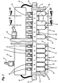
- Fig. 1
- ein Leimaggregat in Queransicht,
- Fig. 2
- das Leimaggregat gemäß
Fig. 1 in Queransicht bzw. im Querschnitt in der Schnittebene II-II derFig. 1 , in vergrößertem Maßstab, - Fig. 3
- eine Queransicht bzw. einen Querschnitt entsprechend
Fig. 2 in der Schnittebene III-III derFig. 1 , - Fig. 4
- eine Einzelheit des Leimaggregats, nämlich ein Ersatz- bzw. Hilfsstück in Unteransicht,
- Fig. 5
- eine Einzelheit des Leimaggregats in der Darstellung gemäß
Fig. 3 . - Die in den Zeichnungen dargestellte Vorrichtung - ein Leimaggregat - dient beispielshaft zur Übertragung von Leimportionen bzw. Leimpunkten 10 auf einzelne Zuschnitte 11 für die Fertigung von Packungen, insbesondere von Klappschachteln für Zigaretten. Es sind mehrere nebeneinanderliegende Leimpunkte 10 auf jeden Zuschnitt 11 zu übertragen. Ein komplexes Leimbild (
EP 0 601 411 A2 ) besteht aus mehreren nebeneinanderliegenden Punktreihen 12 je Zuschnitt 11. InFig. 1 sind jeweils einzelne Leimpunkte 10 von mehreren nebeneinanderliegenden, sich quer zur Zeichnungsebene erstreckenden Punktreihen 12 gezeigt. - Das Leimaggregat umfasst mehrere Leimspender, vorliegend Leimventile 13. Bei dem Ausführungsbeispiel gemäß
Fig. 1 sind sechs Leimventile 13 nebeneinander positioniert und an einem gemeinsamen Träger 14 angebracht. Die Leimventile 13 sind so positioniert, dass die von einer Ventildüse 15 ausgegebenen Leimportionen, nämlich Leimpunkte 10, exakt auf dem Zuschnitt 11 positioniert werden. Das Leimventil 13 kann beispielsweise im Wesentlichen gemäßDE 10 2009 022 496.3 ausgebildet sein, jedoch mit wichtigen Abänderungen, die die Montage und Abnahme des Leimventils erleichtern. Vorzugsweise ist die Anordnung so getroffen, dass das Leimaggregat mit mehreren nebeneinander angeordneten Leimventilen 13 oberhalb einer Bewegungs- bzw. Förderbahn für die Zuschnitte 11 ortsfest positioniert ist. Die mit (geringem Abstand) unterhalb der Leimventile transportierten Zuschnitte 11 (Transportrichtung senkrecht zur Zeichenebene) werden durch kurzzeitiges Öffnen der Leimventile 13 mit dem jeweils erforderlichen Leimbild aus mehreren Punktreihen 12 versehen. - Der Aufbau des Leimaggregats ist bei diesem Beispiel so gewählt, dass der quergerichtete Träger 14 in der Leimstation (einer Verpackungsmaschine) mit Verbindungsmitteln, hier mit Endflanschen 16, an der Konstruktion der Maschine befestigt ist.
- Das Leimaggregat gemäß
Fig. 1 ist auf zweibahnige Betriebsweise ausgerichtet. Es sind demnach zwei Gruppen von Leimventilen 13 an einem gemeinsamen Träger 14 angebracht, wobei jeweils zwei nebeneinanderliegende Zuschnitte 11 unterhalb des so ausgebildeten Leimaggregats (in horizontaler Ebene) transportiert werden. Die (sechs) Leimventile 13 der beiden Arbeitsbahnen sind mit a bis f einerseits und g bis I andererseits inFig. 1 gekennzeichnet. - Vorzugsweise alle Leimventile des Leimaggregats werden über eine gemeinsame Leimleitung mit Leim versorgt. Vorzugsweise ist diese als (quer zur Bewegungsrichtung der Zuschnitte 11) verlaufender Verteilerkanal 17 ausgebildet, vorzugsweise in der Ausführung als durchgehende Bohrung im Träger 14 mit geeignetem (kreisförmigem) Querschnitt. Dem Verteilerkanal 17 wird der Leim über eine Zentralleitung (unter Druck) zugeführt. Diese ist vorzugsweise mittig zwischen den beiden Gruppen der Leimventile 13 mit dem Verteilerkanal 17 verbunden. Vorliegend schließt die Zentralleitung 18 an ein mittleres (aufrechtes) Tragstück 19 an, welches zwischen den beiden Gruppen der Leimventile 13 angeordnet und mit dem Träger 14 verbunden ist. Innerhalb des Tragstücks 19 ist ein Kanal (oder eine Leitung) angeordnet zur Verbindung der Mündung der Zentralleitung 18 mit dem Verteilerkanal 17.
- Der Verteilerkanal 17 besteht demnach funktional aus zwei Abschnitten, die gemeinsam durch die Zentralleitung 18 mit Leim versorgt werden. Je ein Abschnitt des Verteilerkanals 17 führt zu der einen und zu der anderen Gruppe von Leimventilen 13 an dem Träger 14. Das (Quer-)Profil des Trägers 14 ist so ausgebildet, dass ein ausreichend bemessener Verteilerkanal Aufnahme findet. Hierzu ist (randseitig) am Träger 14 ein annähernd quadratisches Kanalprofil 20 gebildet. In diesem verläuft der Verteilerkanal 17, derart, dass alle Leimventile 13 mit Leim versorgt werden können. Das Kanalprofil 20 ist mit einem Flachprofil bzw. einem Tragflansch 21 des Trägers 14 zu einem einheitlichen Profil verbunden. Die Leimventile 13 sind im Bereich des Tragflansches 21 mit dem Träger 14 individuell lösbar verbunden. Vorzugsweise sind die Leimventile 13 an der Unterseite des Trägers 14 angeordnet und durch Schrauben 22, vorliegend durch zwei Schrauben 22 an dem Träger 14 befestigt.
- Der Verteilerkanal 17 ist mit jedem Leimventil 13 über mindestens einen Leimanschluss verbunden. Vorliegend ist ein Abzweigkanal 23 vorgesehen, der vorzugsweise als Bohrung von dem Verteilerkanal 17 zum Leimventil 13 führt und an einen (aufrechten) Leimkanal 24 innerhalb des Leimventils 13 anschließt. Vorteilhafterweise ist das Leimventil 13 so positioniert und der Abzweigkanal 23 so angebracht, dass der Abzweigkanal 23 mit dem Leimkanal 24 eine durchgehende geradlinige Leimleitung bildet, vorzugsweise aufgrund übereinstimmender Abmessungen ohne Absätze oder Vorsprünge, also ein durchgehend einheitlicher Kanal bis zu einer Ventilkammer. Im Bereich des Übergangs von Abzweigkanal 23 zum Leimkanal 24 ist eine Abdichtung angeordnet, nämlich ein Dichtring 46, der vorzugsweise am Leimventil 13, also am Endbereich des Leimkanals 24, angeordnet ist. Im Übrigen entsprechen Aufbau und Funktionsweise des Leimventils im Prinzip dem Leimventil gemäß
DE 10 2009 022 496.3 . - Der Träger 14 ist durch weitere Gestaltungen an eine leichte Montage und Abnahme der Leimventile 13 angepasst. Ein bei den bevorzugt eingesetzten Leimventilen (
DE 10 2009 022 496.3 ) ist eine - etwa mittig liegende - an der oberen Seite des Leimventils 13 zu betätigende Einstellschraube 42 angeordnet. Diese tritt bei der vorliegenden Ausbildung des Trägers 14 durch eine im Tragflansch 21 gebildete Ausnehmung hindurch, die vorliegend als Gewindebohrung 41 ausgebildet ist. Die Einstellschraube 42 wird mit entsprechendem Außengewinde in dieser Gewindebohrung 41 verankert, mit der Möglichkeit der Einstellbarkeit eines Ventil-Organs mit Hilfe dieser frei liegenden Einstellschraube 42. - Zur Übertragung unterschiedlicher Leimbilder auf die Zuschnitte 11 können Leimventile 13 der einen und/oder anderen Gruppe durch Umrüstung entfernt oder von Anfang an bei der Installation des Leimaggregats weggelassen werden.
Fig. 1 zeigt am Beispiel der rechten Arbeitsbahn bzw. der Gruppe der Leimventile 13 g bis I eine Ausführung, bei der zwei Leimventile 13 - im Bereich der Positionen h und k - weggelassen bzw. abgenommen sind. Es werden demnach entsprechend weniger Punktreihen 12 übertragen. - Die Position des bzw. der fehlenden Leimventil(e) 13 wird so versorgt, dass der Betrieb für die übrigen Leimventile der kompletten Gruppe wie auch der Teilgruppe mit den Leimventilen g, i, j, l unverändert und ohne Beeinträchtigung weiterlaufen kann. Zu diesem Zweck ist als erstes der Anschluss des Verteilerkanals 17 an das abgenommene Leimventil 13 bzw. den Leimkanal 24 zu verschließen. Als Besonderheit ist hierfür ein Verschlussorgan vorgesehen, vorzugsweise in der Ausführung eines Verschlusszapfens 25, der über die freie (untere) Seite in den Abzweigkanal 23 eingeführt wird und diesen verschließt. Der Verschlusszapfen 25 hat demnach das Profil und die Abmessung des Abzweigkanals 23. Weiterhin ist der Verschlusszapfen 25 so ausgebildet, dass eine Ergänzung des Querschnittprofils des Verteilerkanals 24 stattfindet. Vorliegend ist der Verschlusszapfen 25 mit einer teilkreisförmigen Ergänzungsfläche 26 versehen, die aufgrund Form und Abmessung bündig mit der (zylindrischen) Innenfläche des Verteilerkanals 17 im Bereich des Abzweigkanals 23 abschließt. Der Leim kann dadurch ohne Beeinträchtigung der Strömung durch den Verteilerkanal 17 hindurchgeleitet werden. Aufgrund der Ausbildung und Abmessung des Verschlusszapfens 25 mit einer schräggerichteten Anschlagfläche 27 und entsprechender Ausbildung des Abzweigkanals 23 wird der Verschlusszapfen 25 selbstjustierend in der durch den Abzweigkanal 23 gebildeten Ausnehmung positioniert. Das Verschlussorgan bzw. der Verschlusszapfen 25 ist gegen Durchtritt von Material abgedichtet, vorliegend durch einen Dichtring 28 an der Mündung des Abzweigkanals 23.
- Der Verschlusszapfen 25 ist an einem Tragorgan angebracht, welches mit dem Träger 14 des Leimaggregats verbunden wird. Vorliegend ist der Verschlusszapfen 25 an einem Ersatzstück 29 angebracht, welches anstelle des abgenommenen bzw. fehlenden Leimventils 13 am Träger 14 angebracht ist, vorzugsweise durch gleiche oder durch dieselben Hilfsmittel - Schrauben 22 - mit denen das Leimventil 13 am Träger 14 angebracht ist. Das Ersatzstück 29 ist im Wesentlichen als quer zum Träger 14 gerichteter Steg ausgebildet, an dessen einem Ende der in einer entsprechenden Bohrung verankerte Verschlusszapfen 25 angebracht ist. Der Dichtring 28 ist an der dem Randprofil 20 zugekehrten (oberen) Fläche angeordnet.
- Bei fehlendem bzw. abgenommenen Leimventil 13 - Positionen h und k in
Fig. 1 - sind weitere Funktionsorgane, die vorzugsweise jedem Leimventil 13 zugeordnet sind, zeitweilig oder dauerhaft zu sichern. Vorzugsweise ist mindestens eine elektrische Leitung, nämlich Steuerleitung 30 dem bzw. jedem Leimventil 13 zugeordnet, nämlich zur Steuerung der Bewegungen eines Ventil-Verschlussorgans. - Der Steuerstrom wird dem Leimaggregat vorzugsweise über eine für alle Leimventile 13 gemeinsame Hauptleitung 31 zugeführt. An diese schließen die einzelnen Steuerleitungen 30 an. Vorliegend mündet die Hauptleitung 31 in einem Verteilergehäuse 32. In diesem ist die Verbindung mit den einzelnen Steuerleitungen 30 untergebracht. Im Bereich jedes Leimventils 13 tritt die Steuerleitung 30 über eine Durchtrittsöffnung 33 in einer den Leimventilen 13 zugekehrten (unteren) Wandung des Verteilergehäuses 32 hindurch. Ein kurzer (aufrechter) Abschnitt der Steuerleitung 30 führt vorzugsweise in Abwärtsrichtung zu dem zugeordneten Leimventil 13.
- Die Steuerleitungen 30 sind an ihrem dem Leimventil 13 zugeordneten Ende mit einem Verbindungsorgan versehen, vorliegend mit einem Stecker 34, der in eine für die Stromübertragung ausgebildete Aufnahme 35 im bzw. am Gehäuse des Leimventils 13 eingeführt wird. Das Ende der Steuerleitung 30 bzw. dessen Stecker 34 wird in der Aufnahme 35 durch eine Übermutter 36 gehalten, die am Stecker 34 angebracht ist und mit einem Außengewinde der Aufnahme 35 am Leimventil 13 zusammenwirkt. Die Stecker-Aufnahme 35 liegt aufgrund der Anordnung des Leimventils 13 und der Abmessung des Trägers 14 außerhalb des Bereichs desselben, ist also ohne Beeinträchtigung durch den Träger 14 frei zugänglich.
- Bei fehlendem bzw. abgenommenen Leimventil 13 bleibt die Steuerleitung 30 samt Stecker 34 im Wesentlichen in der Position und Anordnung entsprechend der Verbindung mit einem Leimventil 13. Am Träger 14 ist ein Haltestück für den Stecker 34 vorgesehen mit einem Außengewinde für die am Stecker 34 angebrachte Übermutter 36.
- Vorteilhaft ist das Haltemittel für den Stecker 34 an dem Ersatzstück 29 angebracht, also an dem Halter für den Verschlusszapfen 25. Das stegförmige Ersatzstück 29 ist mit einem Fortsatz versehen. Gegenüberliegend zum Verschlusszapfen 25 ist das Tragorgan für den Stecker 34 angebracht. Vorteilhafterweise handelt es sich dabei um einen Schraubenbolzen 37, der (von unten) in das Ersatzstück 29 eingeführt und an diesem durch eine Schraubenmutter 43 fixiert ist. An dem freien (oberen) Ende des Schraubenbolzens 37 ist eine dem Stecker 34 zugekehrte axiale Vertiefung gebildet. Diese ist in Form und Größe an das Ende des Steckers 34 angepasst. Der in die Vertiefung 38 eingeführte Teil des Steckers 34 wird in dieser Stellung durch die Übermutter 36 fixiert, die auf das Außengewinde des Schraubenbolzens 37 abgestimmt ist.
- Einige oder alle Leimventile 13 sind mit einem Sensor versehen, der auf das jeweils herzustellende Beleimungsprogramm bzw. auf das Leimbild abgestimmt ist. Bei Fehlmontage, also bei einer Falschauswechslung eines Leimventils 13, wird eine Fehlersignal erzeugt.
- Vorliegend ist ein Signalgeber 39 an dem Ersatzstück 29 angeordnet und so wirksam, dass ein Fehlersignal ausgelöst wird, wenn ein Ersatzstück 29 an falscher Stelle montiert oder versäumt worden ist, ein Leimventil abzunehmen und durch ein Ersatzstück 29 zu ersetzen. Der Signalgeber 39 ist als elektrisches Hilfsmittel ausgebildet, nämlich als ohmscher Widerstand oder als kapazitive Last. Vorteilhaft ist ein Signalgeber mit einem Widerstand der geringer ist als der Spulenwiderstand des Leimventils, insbesondere etwa die Hälfte beträgt. Bei Fehlbesetzung einer Position für ein Leimventil misst die Steuerung des Leimaggregats beispielsweise in einem Bereich, in dem ein auszuwechselndes Leimventil durch Fehler vorhanden ist den "normalen" Spulenwiderstand und erzeugt eine Fehlermeldung. Wenn korrekterweise das Ersatzstück 29 eingesetzt ist, wird der korrekte Widerstand gemessen und ein Fehlersignal nicht erzeugt. Wenn hingegen bei abgenommenem Leimventil das Ersatzstück 29 korrekt in Position gebracht, der Stecker 34 aber nicht in der Aufnahme 35 sitzt, wird ein fehlerhafter (unendlicher) Widerstand gemessen und dadurch ebenfalls eine Fehlermeldung ausgelöst. Der Signalgeber 39 bzw. der Widerstand ist in der Vertiefung 38 des Schraubenbolzens 37 angeordnet und durch eine Vergussmasse 40 fixiert. Durch Einführen des Steckers 34 in die Vertiefung 38 wird der Kontakt mit dem Signalgeber 39 bzw. Widerstand hergestellt.
- Eine andere Besonderheit des Leimaggregats besteht darin, dass der Druck in dem Leimsystem, insbesondere im Verteilerkanal 17, durch Drucksensoren 44 überprüft wird. Diese sind vorzugsweise an beiden Enden des sich über die volle Länge des Trägers 14 erstreckenden Verteilerkanals 17 angeordnet. Die Drucksensoren 44 sind über Messleitungen 45 mit dem elektrischen Steuersystem im Verteilergehäuse 32 verbunden, derart, dass bei einem Druckabfall im Verteilerkanal 17 ein entsprechendes Signal erzeugt wird.
Claims (11)
- Vorrichtung zum Auftragen von Leim auf Trägermaterial, insbesondere auf Zuschnitte (11) zum Herstellen von Packungen, mittels Leimaggregat, welches eine Mehrzahl von vorzugsweise nebeneinander angeordneten und durch einen Träger (14) gehaltene Leimventile (13) aufweist, denen Leim über zu jedem Leimventil (13) führende Leimleitungen zuführbar ist, gekennzeichnet durch folgende Merkmale:a) einzelne oder alle Leimventile (13) sind abnehmbar an einem vorzugsweise gemeinsamen Träger (14) des Leimaggregats angebracht,b) zum zeitweiligen Außerbetriebsetzen eines oder mehrerer Leimventil (13) ist das betreffende Leimventil von dem Träger (14) abnehmbar,c) an die Stelle des abgenommenen Leimventils (13) ist ein Ersatzstück (29) am Träger (13) anbringbar,d) das Ersatzstück (29) ist mit einem Verschlussorgan für einen Verteilerkanal (17) für die Zuführung von Leim und/oder einen an den Verteilerkanal (17) anschließenden, zum Leimventil (13) führenden Abzweigkanal (23) versehen, der bei Positionierung des Ersatzstücks (29) am Träger (13) die Absperrung bewirkt.e) das Verschlussorgan (25) ist aufgrund entsprechender Formgebung, insbesondere aufgrund einer gewölbten Ergänzungsfläche (26), so ausgebildet, dass in Verschlussstellung im Abzweigkanal (23) eine Innenwandung bzw. Innenfläche des Verteilerkanals (17) formschlüssig, absatzfrei im Bereich des Verschlussorgans (25) ergänzt ist.
- Vorrichtung zum Auftragen von Leim auf Trägermaterial, insbesondere auf Zuschnitte (11) zum Herstellen von Packungen, mittels Leimaggregat, welches eine Mehrzahl von vorzugsweise nebeneinander angeordneten und durch einen Träger (14) gehaltene Leimventile (13) aufweist, denen Leim über zu jedem Leimventil (13) führende Leimleitungen zuführbar ist, gekennzeichnet durch folgende Merkmale:a) einzelne oder alle Leimventilen (13) sind abnehmbar an einem vorzugsweise gemeinsamen Träger (14) des Leimaggregats angebracht,b) zum zeitweiligen Außerbetriebsetzen eines oder mehrerer Leimventil (13) ist das betreffende Leimventil von dem Träger (14) abnehmbar,c) an die Stelle des abgenommenen Leimventils (13) ist ein Ersatzstück (29) am Träger (13) anbringbar,d) das Ersatzstück (29) ist mit einem Verschlussorgan für einen Verteilerkanal (17) für die Zuführung von Leim und/oder einen an den Verteilerkanal (17) anschließenden, zum Leimventil (13) führenden Abzweigkanal (23) versehen, der bei Positionierung des Ersatzstücks (29) am Träger (13) die Absperrung bewirkt,e) das Ersatzstück (29) ist stegartig ausgebildet, erstreckt sich quer zum Träger (14) und ist vorzugsweise unterhalb desselben angebracht, wobei ein freier, über den Träger (14) hinweg ragender Endbereich Aufnahmen bzw. Halter für weitere Funktionsorgane des Leimventils (13) aufweist, insbesondere eine Aufnahme bzw. Halterung für ein freies Ende - Stecker (34) - einer (elektrischen) Steuerleitung (30).
- Vorrichtung zum Auftragen von Leim auf Trägermaterial, insbesondere auf Zuschnitte (11) zum Herstellen von Packungen, mittels Leimaggregat, welches eine Mehrzahl von vorzugsweise nebeneinander angeordneten und durch einen Träger (14) gehaltene Leimventile (13) aufweist, denen Leim über zu jedem Leimventil (13) führende Leimleitungen zuführbar ist, gekennzeichnet durch folgende Merkmale:a) einzelne oder alle Leimventilen (13) sind abnehmbar an einem vorzugsweise gemeinsamen Träger (14) des Leimaggregats angebracht.b) zum zeitweiligen Außerbetriebsetzen eines oder mehrerer Leimventil (13) ist das betreffende Leimventil von dem Träger (14) abnehmbar,c) an die Stelle des abgenommenen Leimventils (13) ist ein Ersatzstück (29) am Träger (13) anbringbar,d) das Ersatzstück (29) ist mit einem Verschlussorgan für einen Verteilerkanal (17) für die Zuführung von Leim und/oder einen an den Verteilerkanal (17) anschließenden, zum Leimventil (13) führenden Abzweigkanal (23) versehen, der bei Positionierung des Ersatzstücks (29) am Träger (13) die Absperrung bewirkt,e) jedem Leimventil (13) ist mindestens ein Sensor zugeordnet, der auf mangelnde oder fehlerhafte Auswechslungen von Leimventilen (13) anspricht und ein Fehlersignal erzeugt, wobei vorzugsweise in der Vertiefung (38) eines Schraubenbolzens (37) eines jeden Ersatzstücks (29) ein Signalgeber (39) angeordnet ist, der mit dem Stecker (34) der Steuerleitung (30) zusammenwirkt, insbesondere einen gegenüber dem Widerstand einer elektrischen Spule des Leimventils abweichenden Widerstand aufweist und über die Steuerleitung (13) auf übereinstimmenden Widerstand bzw. auf Widerstandsdifferenzen reagiert.
- Vorrichtung nach Anspruch 1, 2 oder 3, dadurch gekennzeichnet, dass das Ersatzstück (29) nach Abnehmen eines Leimventils (13) im Wesentlichen in der Position des Leimventils (13) am Träger (14) befestigt ist, vorzugsweise mit den selben bzw. gleichen Verbindungsmitteln wie das Leimventil (13) - Schrauben (22).
- Vorrichtung nach Anspruch 1, 2, 3 oder 4, dadurch gekennzeichnet, dass der Verschlusszapfen (25) an der dem Abzweigkanal (23) zugeordneten (oberen) Seite des Ersatzstücks (29) angeordnet ist, derart, dass bei Positionierung des Ersatzstücks (29) am Träger (14) der Verschlusszapfen (25) in Verschlussstellung innerhalb des Abzweigkanals (23) positioniert ist.
- Vorrichtung nach Anspruch 1, 2, 3 oder einem der weiteren Ansprüche, dadurch gekennzeichnet, dass der Verschlusszapfen (25) in der Schließstellung gegenüber dem Inneren des Verteilerkanals (17) abgedichtet ist, insbesondere durch einen am Ersatzstück (29) angeordneten, den Verschlusszapfen (25) an einer dem Träger (14) zugekehrten (oberen) Seite umgebenden Dichtring (28).
- Vorrichtung nach Anspruch 2 oder einem der weiteren Ansprüche, dadurch gekennzeichnet, dass die am Ersatzstück (29) angebrachte Aufnahme für den endseitigen Stecker (34) der Steuerleitung (30) eine nach oben offene Vertiefung (38) aufweist für den Eintritt des Steckers (34) oder eines Teils desselben, wobei vorzugsweise die Vertiefung (38) in einem aufrechten Schraubenbolzen (37) gebildet und der Stecker (34) in der Vertiefung (38) durch eine Übermutter (36) fixiert ist.
- Vorrichtung nach Anspruch 1, 2, 3 oder einem der weiteren Ansprüche, dadurch gekennzeichnet, dass der vorzugsweise an beiden Enden durch Tragflansche (21) fixierte Träger (14) eine Profilerweiterung aufweist für die Aufnahme des als durchgehende Bohrung ausgebildeten Verteilerkanals, insbesondere ein Kanalprofil (20), an das ein Tragflansch (21) anschließt, wobei der Träger (14) Bohrungen für den Anschluss des Leimventils (13) aufweist, insbesondere eine Gewindebohrung, (41) für eine Einstellschraube (42) und für (zwei) Schrauben (22) zur Befestigung des Leimventils (13) am Träger (14).
- Vorrichtung nach Anspruch 1, 2, 3 oder einem der weiteren Ansprüche, dadurch gekennzeichnet, dass das Leimventil (13) einen vorzugsweise aufrechten Leimkanal (24) aufweist, der im Bereich des Abzweigkanals (23) für die Zuführung des Leims mündet und mit dem Abzweigkanal (23) bündig abschließt, derart, dass eine Leimleitung vom Verteilerkanal (17) über den Abzweigkanal (23) und den Leimkanal (24) bis zu einer Ventilkammer gebildet ist, wobei vorzugsweise am Leimventil (13) ein die Mündung des Leimkanals (24) umgebender Dichtring (46) angeordnet ist.
- Vorrichtung nach Anspruch 1, 2, 3 oder einem der weiteren Ansprüche, dadurch gekennzeichnet, dass der Anschluss für die Steuerleitung (30) an das Leimventil (13), insbesondere eine Aufnahme (35) für einen Stecker (34) der Steuerleitung (30), außerhalb des Bereichs des Trägers (14) frei zugänglich angeordnet ist.
- Vorrichtung nach Anspruch 1, 2, 3 oder einem der weiteren Ansprüche, dadurch gekennzeichnet, dass eine Hauptleitung (31) zur Stromversorgung der Steuerleitungen (30) an ein vorzugsweise langgestrecktes, quergerichtetes Verteilergehäuse (32) anschließt, von dem einzelne Steuerleitungen (30) zu den Leimventilen (13) führen.
Priority Applications (1)
| Application Number | Priority Date | Filing Date | Title |
|---|---|---|---|
| PL11004562T PL2397231T5 (pl) | 2010-06-18 | 2011-06-04 | Sposób i urządzenie do nanoszenia kleju na wykroje |
Applications Claiming Priority (1)
| Application Number | Priority Date | Filing Date | Title |
|---|---|---|---|
| DE102010024361A DE102010024361A1 (de) | 2010-06-18 | 2010-06-18 | Verfahren und Vorrichtung zum Auftragen von Leim auf Zuschnitte |
Publications (3)
| Publication Number | Publication Date |
|---|---|
| EP2397231A1 EP2397231A1 (de) | 2011-12-21 |
| EP2397231B1 EP2397231B1 (de) | 2014-08-13 |
| EP2397231B2 true EP2397231B2 (de) | 2018-04-11 |
Family
ID=44785081
Family Applications (1)
| Application Number | Title | Priority Date | Filing Date |
|---|---|---|---|
| EP11004562.2A Not-in-force EP2397231B2 (de) | 2010-06-18 | 2011-06-04 | Verfahren und Vorrichtung zum Auftragen von Leim auf Zuschnittte |
Country Status (3)
| Country | Link |
|---|---|
| EP (1) | EP2397231B2 (de) |
| DE (1) | DE102010024361A1 (de) |
| PL (1) | PL2397231T5 (de) |
Cited By (2)
| Publication number | Priority date | Publication date | Assignee | Title |
|---|---|---|---|---|
| CN110639828A (zh) * | 2019-09-11 | 2020-01-03 | 西南科技大学 | 多层分类法的卷烟条烟多规格一体化分拣方法 |
| CN111071557A (zh) * | 2019-12-28 | 2020-04-28 | 合肥禄正新能源科技有限公司 | 一种obc+dcdc一体机的包装设备 |
Families Citing this family (8)
| Publication number | Priority date | Publication date | Assignee | Title |
|---|---|---|---|---|
| DE202013100352U1 (de) * | 2013-01-25 | 2014-04-28 | Baumer Hhs Gmbh | Auftragseinrichtung zum Auftrag von fluidem Medium auf ein Substrat |
| CN106563617B (zh) * | 2016-11-15 | 2018-10-09 | 安徽养和医疗器械设备有限公司 | 一种用于呼吸卡涂液装置 |
| DE102017207851B4 (de) * | 2017-05-10 | 2023-02-16 | Audi Ag | Vorrichtung und Verfahren zum Auftragen von flüssigem Klebstoff |
| CN107930985B (zh) * | 2017-12-04 | 2021-01-26 | 芜湖华烨新材料有限公司 | 一种上胶装置 |
| CN108405263B (zh) * | 2018-05-09 | 2024-07-02 | 苏州丰川电子科技有限公司 | 用于高精密笔记本上盖冲压件的加工装置 |
| CN113385368A (zh) * | 2021-05-13 | 2021-09-14 | 广东科杰机械自动化有限公司 | 多头喷胶装置、喷胶设备及喷胶方法 |
| DE102023128194A1 (de) * | 2023-10-16 | 2025-04-17 | Khs Gmbh | Verteileinheit für eine Applikationseinrichtung, Applikationseinrichtung mit einer entsprechenden Verteileinheit, Beleimungsstation mit einer Vielzahl von Applikationseinrichtungen und Verfahren zum additiven Fertigen einer Verteileinheit |
| CN117543064B (zh) * | 2024-01-08 | 2024-04-02 | 深圳市铭镭激光设备有限公司 | 一种新能源电池模组全自动生产线 |
Citations (5)
| Publication number | Priority date | Publication date | Assignee | Title |
|---|---|---|---|---|
| US3135628A (en) † | 1961-05-11 | 1964-06-02 | Sunkist Growers Inc | Apparatus for coating with adhesive or other fluent materials |
| US3298353A (en) † | 1963-09-03 | 1967-01-17 | Hamilton Tool Co | Multiple orifice glue applicator |
| DE3506393A1 (de) † | 1985-02-23 | 1986-08-28 | Windmöller & Hölscher, 4540 Lengerich | Leimauftragsvorrichtung |
| US4744330A (en) † | 1985-12-04 | 1988-05-17 | Claassen Henning J | Device for intermittent application of liquids such as adhesive |
| EP0410400B1 (de) † | 1989-07-28 | 1993-11-03 | PLANATOL - Klebetechnik Gesellschaft mit beschränkter Haftung | Vorrichtung zur Materialversorgung von Falzklebe- und Befeuchtungsanlagen an Rotationsdruckmaschinen |
Family Cites Families (13)
| Publication number | Priority date | Publication date | Assignee | Title |
|---|---|---|---|---|
| US4488665A (en) * | 1982-05-24 | 1984-12-18 | Spraymation, Inc. | Multiple-outlet adhesive applicator apparatus and method |
| US5172833A (en) * | 1992-01-09 | 1992-12-22 | Slautterback Corporation | Modular applicator having a separate flow loop to prevent stagnant regions |
| DE9201387U1 (de) * | 1992-02-05 | 1992-05-21 | Bierther, Hans-Dietmar, 6200 Wiesbaden | Auftragskopf |
| DE4241176B4 (de) | 1992-12-08 | 2005-12-22 | Focke & Co.(Gmbh & Co. Kg) | Vorrichtung zum Auftragen von Leim auf Zuschnitte für Klappschachteln |
| DE9310427U1 (de) * | 1993-07-13 | 1994-11-10 | ITW Dynatec GmbH Klebetechnik, 40699 Erkrath | Vorrichtung zur Zufuhr von Schmelzklebstoffen o.dgl. zu einer mehrere Auftragsköpfe umfassenden Auftragsvorrichtung |
| US5875922A (en) * | 1997-10-10 | 1999-03-02 | Nordson Corporation | Apparatus for dispensing an adhesive |
| US6012503A (en) * | 1997-11-26 | 2000-01-11 | Riverwood International Corporation | Adjustable gluing apparatus for a packaging machine |
| DE10327646B4 (de) * | 2002-09-13 | 2007-07-12 | Windmöller & Hölscher Kg | Vorrichtung zur Bildung eines Leimprofils für Kreuzbodensäcke |
| DE10303285A1 (de) * | 2003-01-28 | 2004-08-05 | Focke Gmbh & Co. Kg | Verfahren und Vorrichtung zum Beleimen von Verpackungsmaterial |
| US20050015050A1 (en) * | 2003-07-15 | 2005-01-20 | Kimberly-Clark Worldwide, Inc. | Apparatus for depositing fluid material onto a substrate |
| DE102008027259A1 (de) * | 2008-06-06 | 2009-12-17 | Focke & Co.(Gmbh & Co. Kg) | Verfahren und Vorrichtung zur Herstellung von Zigarettenpackungen |
| DE102009022496A1 (de) | 2009-05-25 | 2011-01-05 | Focke & Co.(Gmbh & Co. Kg) | Ventil, insbesondere Leimventil |
| DE102009034687B4 (de) * | 2009-07-24 | 2017-03-30 | Windmöller & Hölscher Kg | Vorrichtung und Verfahren zum Versehen von Werkstücken oder Bahnen mit Leim |
-
2010
- 2010-06-18 DE DE102010024361A patent/DE102010024361A1/de not_active Withdrawn
-
2011
- 2011-06-04 EP EP11004562.2A patent/EP2397231B2/de not_active Not-in-force
- 2011-06-04 PL PL11004562T patent/PL2397231T5/pl unknown
Patent Citations (5)
| Publication number | Priority date | Publication date | Assignee | Title |
|---|---|---|---|---|
| US3135628A (en) † | 1961-05-11 | 1964-06-02 | Sunkist Growers Inc | Apparatus for coating with adhesive or other fluent materials |
| US3298353A (en) † | 1963-09-03 | 1967-01-17 | Hamilton Tool Co | Multiple orifice glue applicator |
| DE3506393A1 (de) † | 1985-02-23 | 1986-08-28 | Windmöller & Hölscher, 4540 Lengerich | Leimauftragsvorrichtung |
| US4744330A (en) † | 1985-12-04 | 1988-05-17 | Claassen Henning J | Device for intermittent application of liquids such as adhesive |
| EP0410400B1 (de) † | 1989-07-28 | 1993-11-03 | PLANATOL - Klebetechnik Gesellschaft mit beschränkter Haftung | Vorrichtung zur Materialversorgung von Falzklebe- und Befeuchtungsanlagen an Rotationsdruckmaschinen |
Cited By (3)
| Publication number | Priority date | Publication date | Assignee | Title |
|---|---|---|---|---|
| CN110639828A (zh) * | 2019-09-11 | 2020-01-03 | 西南科技大学 | 多层分类法的卷烟条烟多规格一体化分拣方法 |
| CN110639828B (zh) * | 2019-09-11 | 2021-09-21 | 西南科技大学 | 多层分类法的卷烟条烟多规格一体化分拣方法 |
| CN111071557A (zh) * | 2019-12-28 | 2020-04-28 | 合肥禄正新能源科技有限公司 | 一种obc+dcdc一体机的包装设备 |
Also Published As
| Publication number | Publication date |
|---|---|
| PL2397231T5 (pl) | 2018-08-31 |
| EP2397231B1 (de) | 2014-08-13 |
| PL2397231T3 (pl) | 2015-02-27 |
| DE102010024361A1 (de) | 2011-12-22 |
| EP2397231A1 (de) | 2011-12-21 |
Similar Documents
| Publication | Publication Date | Title |
|---|---|---|
| EP2397231B2 (de) | Verfahren und Vorrichtung zum Auftragen von Leim auf Zuschnittte | |
| EP0601411B1 (de) | Verfahren und Vorrichtung zum Auftragen von Leim auf einen Zuschnitt für Klappschachteln | |
| EP0920919B1 (de) | Klappschachtel für Zigaretten sowie Verfahren und Vorrichtung zum Beleimen von Verpackungsmaterial | |
| DE3506393A1 (de) | Leimauftragsvorrichtung | |
| DE102013004448B3 (de) | Vorrichtung zum Umreifen von Packstücken | |
| EP2363359B1 (de) | Fördereinrichtung mit einem Geländer | |
| EP0727357B1 (de) | Aseptisch arbeitende FFS-Maschine | |
| WO2012139907A1 (de) | Formateinstellvorrichtung | |
| DE102010039133A1 (de) | Halterungsanordnung zur Halterung von Systemen sowie Luft- oder Raumfahrzeug | |
| WO2022223377A1 (de) | Dosiermodul | |
| DE3509711C2 (de) | Vorrichtung zur Zufuhr von Zigaretten zur Umhüllungsstrecke einer Verpackungsmaschine | |
| EP2948382B1 (de) | Auftragseinrichtung zum auftrag von fluidem medium auf ein substrat | |
| DE102006028815B3 (de) | Verfahren zur Herstellung eines elektrischen Hybridbauteils | |
| DE4115544A1 (de) | Einheit zum zufuehren von produkten zu einer herstellungsmaschine | |
| EP2354563A1 (de) | Ventilanordnung | |
| EP1975072A1 (de) | Zuführung | |
| DE102015106861B4 (de) | Vorrichtung zum Etikettieren von einzelnen Produkten | |
| EP0930130B1 (de) | Spannvorrichtung | |
| EP0681545A1 (de) | Vorrichtung zum prüfen von zigaretten. | |
| EP3044100A1 (de) | Formatteil sowie formatteilbefestigung | |
| EP1937560B1 (de) | Vorrichtung zum etikettieren von an einer packstoffbahn ausgeformten bechern | |
| EP2239469A2 (de) | Ventilanordnung | |
| DE29905345U1 (de) | Vorrichtung zur dosierten Abgabe von strömenden Medien | |
| DE102017105013B4 (de) | Tintenstrahldrucker für die Beschriftung von Waren mit einem Schreibkopf, einem Vorratsbehälter und einer Halteeinrichtung | |
| WO2025082817A1 (de) | Verteileinheit für eine applikationseinrichtung, applikationseinrichtung mit einer entsprechenden verteileinheit, beleimungsstation mit einer vielzahl von applikationseinrichtungen, gebindebildevorrichtung und verfahren zum additiven fertigen einer verteileinheit |
Legal Events
| Date | Code | Title | Description |
|---|---|---|---|
| AK | Designated contracting states |
Kind code of ref document: A1 Designated state(s): AL AT BE BG CH CY CZ DE DK EE ES FI FR GB GR HR HU IE IS IT LI LT LU LV MC MK MT NL NO PL PT RO RS SE SI SK SM TR |
|
| AX | Request for extension of the european patent |
Extension state: BA ME |
|
| PUAI | Public reference made under article 153(3) epc to a published international application that has entered the european phase |
Free format text: ORIGINAL CODE: 0009012 |
|
| 17P | Request for examination filed |
Effective date: 20111128 |
|
| RIC1 | Information provided on ipc code assigned before grant |
Ipc: B05C 5/02 20060101AFI20131204BHEP |
|
| GRAP | Despatch of communication of intention to grant a patent |
Free format text: ORIGINAL CODE: EPIDOSNIGR1 |
|
| INTG | Intention to grant announced |
Effective date: 20140213 |
|
| GRAS | Grant fee paid |
Free format text: ORIGINAL CODE: EPIDOSNIGR3 |
|
| GRAA | (expected) grant |
Free format text: ORIGINAL CODE: 0009210 |
|
| AK | Designated contracting states |
Kind code of ref document: B1 Designated state(s): AL AT BE BG CH CY CZ DE DK EE ES FI FR GB GR HR HU IE IS IT LI LT LU LV MC MK MT NL NO PL PT RO RS SE SI SK SM TR |
|
| REG | Reference to a national code |
Ref country code: GB Ref legal event code: FG4D Free format text: NOT ENGLISH |
|
| REG | Reference to a national code |
Ref country code: AT Ref legal event code: REF Ref document number: 681872 Country of ref document: AT Kind code of ref document: T Effective date: 20140815 Ref country code: CH Ref legal event code: EP |
|
| REG | Reference to a national code |
Ref country code: IE Ref legal event code: FG4D Free format text: LANGUAGE OF EP DOCUMENT: GERMAN |
|
| REG | Reference to a national code |
Ref country code: DE Ref legal event code: R096 Ref document number: 502011004001 Country of ref document: DE Effective date: 20140925 |
|
| REG | Reference to a national code |
Ref country code: NL Ref legal event code: VDEP Effective date: 20140813 |
|
| REG | Reference to a national code |
Ref country code: LT Ref legal event code: MG4D |
|
| PG25 | Lapsed in a contracting state [announced via postgrant information from national office to epo] |
Ref country code: NO Free format text: LAPSE BECAUSE OF FAILURE TO SUBMIT A TRANSLATION OF THE DESCRIPTION OR TO PAY THE FEE WITHIN THE PRESCRIBED TIME-LIMIT Effective date: 20141113 Ref country code: BG Free format text: LAPSE BECAUSE OF FAILURE TO SUBMIT A TRANSLATION OF THE DESCRIPTION OR TO PAY THE FEE WITHIN THE PRESCRIBED TIME-LIMIT Effective date: 20141113 Ref country code: LT Free format text: LAPSE BECAUSE OF FAILURE TO SUBMIT A TRANSLATION OF THE DESCRIPTION OR TO PAY THE FEE WITHIN THE PRESCRIBED TIME-LIMIT Effective date: 20140813 Ref country code: SE Free format text: LAPSE BECAUSE OF FAILURE TO SUBMIT A TRANSLATION OF THE DESCRIPTION OR TO PAY THE FEE WITHIN THE PRESCRIBED TIME-LIMIT Effective date: 20140813 Ref country code: GR Free format text: LAPSE BECAUSE OF FAILURE TO SUBMIT A TRANSLATION OF THE DESCRIPTION OR TO PAY THE FEE WITHIN THE PRESCRIBED TIME-LIMIT Effective date: 20141114 Ref country code: ES Free format text: LAPSE BECAUSE OF FAILURE TO SUBMIT A TRANSLATION OF THE DESCRIPTION OR TO PAY THE FEE WITHIN THE PRESCRIBED TIME-LIMIT Effective date: 20140813 Ref country code: PT Free format text: LAPSE BECAUSE OF FAILURE TO SUBMIT A TRANSLATION OF THE DESCRIPTION OR TO PAY THE FEE WITHIN THE PRESCRIBED TIME-LIMIT Effective date: 20141215 Ref country code: FI Free format text: LAPSE BECAUSE OF FAILURE TO SUBMIT A TRANSLATION OF THE DESCRIPTION OR TO PAY THE FEE WITHIN THE PRESCRIBED TIME-LIMIT Effective date: 20140813 |
|
| PG25 | Lapsed in a contracting state [announced via postgrant information from national office to epo] |
Ref country code: RS Free format text: LAPSE BECAUSE OF FAILURE TO SUBMIT A TRANSLATION OF THE DESCRIPTION OR TO PAY THE FEE WITHIN THE PRESCRIBED TIME-LIMIT Effective date: 20140813 Ref country code: LV Free format text: LAPSE BECAUSE OF FAILURE TO SUBMIT A TRANSLATION OF THE DESCRIPTION OR TO PAY THE FEE WITHIN THE PRESCRIBED TIME-LIMIT Effective date: 20140813 Ref country code: IS Free format text: LAPSE BECAUSE OF FAILURE TO SUBMIT A TRANSLATION OF THE DESCRIPTION OR TO PAY THE FEE WITHIN THE PRESCRIBED TIME-LIMIT Effective date: 20141213 Ref country code: CY Free format text: LAPSE BECAUSE OF FAILURE TO SUBMIT A TRANSLATION OF THE DESCRIPTION OR TO PAY THE FEE WITHIN THE PRESCRIBED TIME-LIMIT Effective date: 20140813 Ref country code: HR Free format text: LAPSE BECAUSE OF FAILURE TO SUBMIT A TRANSLATION OF THE DESCRIPTION OR TO PAY THE FEE WITHIN THE PRESCRIBED TIME-LIMIT Effective date: 20140813 |
|
| REG | Reference to a national code |
Ref country code: PL Ref legal event code: T3 |
|
| PG25 | Lapsed in a contracting state [announced via postgrant information from national office to epo] |
Ref country code: NL Free format text: LAPSE BECAUSE OF FAILURE TO SUBMIT A TRANSLATION OF THE DESCRIPTION OR TO PAY THE FEE WITHIN THE PRESCRIBED TIME-LIMIT Effective date: 20140813 |
|
| PG25 | Lapsed in a contracting state [announced via postgrant information from national office to epo] |
Ref country code: DK Free format text: LAPSE BECAUSE OF FAILURE TO SUBMIT A TRANSLATION OF THE DESCRIPTION OR TO PAY THE FEE WITHIN THE PRESCRIBED TIME-LIMIT Effective date: 20140813 Ref country code: RO Free format text: LAPSE BECAUSE OF FAILURE TO SUBMIT A TRANSLATION OF THE DESCRIPTION OR TO PAY THE FEE WITHIN THE PRESCRIBED TIME-LIMIT Effective date: 20140813 Ref country code: SK Free format text: LAPSE BECAUSE OF FAILURE TO SUBMIT A TRANSLATION OF THE DESCRIPTION OR TO PAY THE FEE WITHIN THE PRESCRIBED TIME-LIMIT Effective date: 20140813 Ref country code: EE Free format text: LAPSE BECAUSE OF FAILURE TO SUBMIT A TRANSLATION OF THE DESCRIPTION OR TO PAY THE FEE WITHIN THE PRESCRIBED TIME-LIMIT Effective date: 20140813 Ref country code: CZ Free format text: LAPSE BECAUSE OF FAILURE TO SUBMIT A TRANSLATION OF THE DESCRIPTION OR TO PAY THE FEE WITHIN THE PRESCRIBED TIME-LIMIT Effective date: 20140813 |
|
| REG | Reference to a national code |
Ref country code: DE Ref legal event code: R026 Ref document number: 502011004001 Country of ref document: DE |
|
| PLBI | Opposition filed |
Free format text: ORIGINAL CODE: 0009260 |
|
| 26 | Opposition filed |
Opponent name: G.D S.P.A. Effective date: 20150511 |
|
| PLAX | Notice of opposition and request to file observation + time limit sent |
Free format text: ORIGINAL CODE: EPIDOSNOBS2 |
|
| PLAF | Information modified related to communication of a notice of opposition and request to file observations + time limit |
Free format text: ORIGINAL CODE: EPIDOSCOBS2 |
|
| PG25 | Lapsed in a contracting state [announced via postgrant information from national office to epo] |
Ref country code: SI Free format text: LAPSE BECAUSE OF FAILURE TO SUBMIT A TRANSLATION OF THE DESCRIPTION OR TO PAY THE FEE WITHIN THE PRESCRIBED TIME-LIMIT Effective date: 20140813 |
|
| PLBB | Reply of patent proprietor to notice(s) of opposition received |
Free format text: ORIGINAL CODE: EPIDOSNOBS3 |
|
| PG25 | Lapsed in a contracting state [announced via postgrant information from national office to epo] |
Ref country code: MC Free format text: LAPSE BECAUSE OF FAILURE TO SUBMIT A TRANSLATION OF THE DESCRIPTION OR TO PAY THE FEE WITHIN THE PRESCRIBED TIME-LIMIT Effective date: 20140813 |
|
| REG | Reference to a national code |
Ref country code: CH Ref legal event code: PL |
|
| PG25 | Lapsed in a contracting state [announced via postgrant information from national office to epo] |
Ref country code: LU Free format text: LAPSE BECAUSE OF FAILURE TO SUBMIT A TRANSLATION OF THE DESCRIPTION OR TO PAY THE FEE WITHIN THE PRESCRIBED TIME-LIMIT Effective date: 20150604 |
|
| REG | Reference to a national code |
Ref country code: IE Ref legal event code: MM4A |
|
| REG | Reference to a national code |
Ref country code: FR Ref legal event code: ST Effective date: 20160229 |
|
| PG25 | Lapsed in a contracting state [announced via postgrant information from national office to epo] |
Ref country code: LI Free format text: LAPSE BECAUSE OF NON-PAYMENT OF DUE FEES Effective date: 20150630 Ref country code: CH Free format text: LAPSE BECAUSE OF NON-PAYMENT OF DUE FEES Effective date: 20150630 Ref country code: IE Free format text: LAPSE BECAUSE OF NON-PAYMENT OF DUE FEES Effective date: 20150604 |
|
| PG25 | Lapsed in a contracting state [announced via postgrant information from national office to epo] |
Ref country code: FR Free format text: LAPSE BECAUSE OF NON-PAYMENT OF DUE FEES Effective date: 20150630 |
|
| PG25 | Lapsed in a contracting state [announced via postgrant information from national office to epo] |
Ref country code: MT Free format text: LAPSE BECAUSE OF FAILURE TO SUBMIT A TRANSLATION OF THE DESCRIPTION OR TO PAY THE FEE WITHIN THE PRESCRIBED TIME-LIMIT Effective date: 20140813 |
|
| PG25 | Lapsed in a contracting state [announced via postgrant information from national office to epo] |
Ref country code: HU Free format text: LAPSE BECAUSE OF FAILURE TO SUBMIT A TRANSLATION OF THE DESCRIPTION OR TO PAY THE FEE WITHIN THE PRESCRIBED TIME-LIMIT; INVALID AB INITIO Effective date: 20110604 Ref country code: SM Free format text: LAPSE BECAUSE OF FAILURE TO SUBMIT A TRANSLATION OF THE DESCRIPTION OR TO PAY THE FEE WITHIN THE PRESCRIBED TIME-LIMIT Effective date: 20140813 |
|
| PG25 | Lapsed in a contracting state [announced via postgrant information from national office to epo] |
Ref country code: BE Free format text: LAPSE BECAUSE OF NON-PAYMENT OF DUE FEES Effective date: 20150630 |
|
| REG | Reference to a national code |
Ref country code: AT Ref legal event code: MM01 Ref document number: 681872 Country of ref document: AT Kind code of ref document: T Effective date: 20160604 |
|
| PG25 | Lapsed in a contracting state [announced via postgrant information from national office to epo] |
Ref country code: TR Free format text: LAPSE BECAUSE OF FAILURE TO SUBMIT A TRANSLATION OF THE DESCRIPTION OR TO PAY THE FEE WITHIN THE PRESCRIBED TIME-LIMIT Effective date: 20140813 |
|
| PG25 | Lapsed in a contracting state [announced via postgrant information from national office to epo] |
Ref country code: AT Free format text: LAPSE BECAUSE OF NON-PAYMENT OF DUE FEES Effective date: 20160604 |
|
| PUAH | Patent maintained in amended form |
Free format text: ORIGINAL CODE: 0009272 |
|
| STAA | Information on the status of an ep patent application or granted ep patent |
Free format text: STATUS: PATENT MAINTAINED AS AMENDED |
|
| 27A | Patent maintained in amended form |
Effective date: 20180411 |
|
| AK | Designated contracting states |
Kind code of ref document: B2 Designated state(s): AL AT BE BG CH CY CZ DE DK EE ES FI FR GB GR HR HU IE IS IT LI LT LU LV MC MK MT NL NO PL PT RO RS SE SI SK SM TR |
|
| REG | Reference to a national code |
Ref country code: DE Ref legal event code: R102 Ref document number: 502011004001 Country of ref document: DE |
|
| PG25 | Lapsed in a contracting state [announced via postgrant information from national office to epo] |
Ref country code: MK Free format text: LAPSE BECAUSE OF FAILURE TO SUBMIT A TRANSLATION OF THE DESCRIPTION OR TO PAY THE FEE WITHIN THE PRESCRIBED TIME-LIMIT Effective date: 20140813 |
|
| PG25 | Lapsed in a contracting state [announced via postgrant information from national office to epo] |
Ref country code: AL Free format text: LAPSE BECAUSE OF FAILURE TO SUBMIT A TRANSLATION OF THE DESCRIPTION OR TO PAY THE FEE WITHIN THE PRESCRIBED TIME-LIMIT Effective date: 20140813 |
|
| PGFP | Annual fee paid to national office [announced via postgrant information from national office to epo] |
Ref country code: DE Payment date: 20200528 Year of fee payment: 10 |
|
| PGFP | Annual fee paid to national office [announced via postgrant information from national office to epo] |
Ref country code: IT Payment date: 20200527 Year of fee payment: 10 Ref country code: GB Payment date: 20200527 Year of fee payment: 10 |
|
| PGFP | Annual fee paid to national office [announced via postgrant information from national office to epo] |
Ref country code: PL Payment date: 20200605 Year of fee payment: 10 |
|
| REG | Reference to a national code |
Ref country code: DE Ref legal event code: R119 Ref document number: 502011004001 Country of ref document: DE |
|
| GBPC | Gb: european patent ceased through non-payment of renewal fee |
Effective date: 20210604 |
|
| PG25 | Lapsed in a contracting state [announced via postgrant information from national office to epo] |
Ref country code: GB Free format text: LAPSE BECAUSE OF NON-PAYMENT OF DUE FEES Effective date: 20210604 Ref country code: DE Free format text: LAPSE BECAUSE OF NON-PAYMENT OF DUE FEES Effective date: 20220101 |
|
| PG25 | Lapsed in a contracting state [announced via postgrant information from national office to epo] |
Ref country code: IT Free format text: LAPSE BECAUSE OF NON-PAYMENT OF DUE FEES Effective date: 20210604 |
|
| PG25 | Lapsed in a contracting state [announced via postgrant information from national office to epo] |
Ref country code: PL Free format text: LAPSE BECAUSE OF NON-PAYMENT OF DUE FEES Effective date: 20210604 |