EP2397078B1 - Fixiervorrichtung für Wundnahtverschluss - Google Patents
Fixiervorrichtung für Wundnahtverschluss Download PDFInfo
- Publication number
- EP2397078B1 EP2397078B1 EP11180293.0A EP11180293A EP2397078B1 EP 2397078 B1 EP2397078 B1 EP 2397078B1 EP 11180293 A EP11180293 A EP 11180293A EP 2397078 B1 EP2397078 B1 EP 2397078B1
- Authority
- EP
- European Patent Office
- Prior art keywords
- suture lock
- suture
- fastening device
- fastening
- retainer
- Prior art date
- Legal status (The legal status is an assumption and is not a legal conclusion. Google has not performed a legal analysis and makes no representation as to the accuracy of the status listed.)
- Not-in-force
Links
Images


Classifications
-
- A—HUMAN NECESSITIES
- A61—MEDICAL OR VETERINARY SCIENCE; HYGIENE
- A61B—DIAGNOSIS; SURGERY; IDENTIFICATION
- A61B17/00—Surgical instruments, devices or methods
- A61B17/04—Surgical instruments, devices or methods for suturing wounds; Holders or packages for needles or suture materials
- A61B17/0487—Suture clamps, clips or locks, e.g. for replacing suture knots; Instruments for applying or removing suture clamps, clips or locks
-
- A—HUMAN NECESSITIES
- A61—MEDICAL OR VETERINARY SCIENCE; HYGIENE
- A61B—DIAGNOSIS; SURGERY; IDENTIFICATION
- A61B17/00—Surgical instruments, devices or methods
- A61B17/04—Surgical instruments, devices or methods for suturing wounds; Holders or packages for needles or suture materials
- A61B17/0485—Devices or means, e.g. loops, for capturing the suture thread and threading it through an opening of a suturing instrument or needle eyelet
-
- A—HUMAN NECESSITIES
- A61—MEDICAL OR VETERINARY SCIENCE; HYGIENE
- A61B—DIAGNOSIS; SURGERY; IDENTIFICATION
- A61B17/00—Surgical instruments, devices or methods
- A61B17/04—Surgical instruments, devices or methods for suturing wounds; Holders or packages for needles or suture materials
- A61B17/0467—Instruments for cutting sutures
-
- A—HUMAN NECESSITIES
- A61—MEDICAL OR VETERINARY SCIENCE; HYGIENE
- A61B—DIAGNOSIS; SURGERY; IDENTIFICATION
- A61B17/00—Surgical instruments, devices or methods
- A61B17/04—Surgical instruments, devices or methods for suturing wounds; Holders or packages for needles or suture materials
- A61B17/0401—Suture anchors, buttons or pledgets, i.e. means for attaching sutures to bone, cartilage or soft tissue; Instruments for applying or removing suture anchors
- A61B2017/0446—Means for attaching and blocking the suture in the suture anchor
- A61B2017/0448—Additional elements on or within the anchor
- A61B2017/045—Additional elements on or within the anchor snug fit within the anchor
-
- A—HUMAN NECESSITIES
- A61—MEDICAL OR VETERINARY SCIENCE; HYGIENE
- A61B—DIAGNOSIS; SURGERY; IDENTIFICATION
- A61B17/00—Surgical instruments, devices or methods
- A61B17/04—Surgical instruments, devices or methods for suturing wounds; Holders or packages for needles or suture materials
- A61B17/0487—Suture clamps, clips or locks, e.g. for replacing suture knots; Instruments for applying or removing suture clamps, clips or locks
- A61B2017/0488—Instruments for applying suture clamps, clips or locks
Definitions
- This invention relates to a suture lock fastening device used to secure sutures.
- Suture locks are used in surgical procedures to obviate the need for tying knots in a suture.
- Suture locks may be particularly useful for endoscopic procedures where tying a knot in a suture may be particularly cumbersome.
- Fastening devices may be used to deliver and position a suture lock at a desired location of a suture. The fastening device may then be used to cinch or lock the suture with the suture lock. Examples of various suture locks and fastening devices for fastening a suture lock are disclosed in U.S. Patent No. 5,584,861 and U.S. Patent Application Publications 2003/0167062 ; 2003/0171760 and 2005/0033319 .
- a suture lock fastening device is disclosed in US6086608 .
- a suture lock fastening device is characterised by the features recited in the characterising portion of claim 1.
- the present invention is directed to a suture lock fastening device that facilitates the fastening of a suture lock.
- the fastening device may be configured for endoscopic delivery of the suture lock to a surgical site within a patient.
- the fastening device may have an elongated, slender configuration that is insertable through a working or biopsy port of an endoscope.
- Illustrative embodiments of the suture lock fastening device may include a fastening head at a distal end thereof that is operatively coupled to an actuation handle at a proximal end thereof. Operation of the handle actuates the fastening head so as to fasten the suture lock onto a suture and thereby cinch or lock the suture.
- the fastening head may also sever the suture proximate to the suture lock.
- the fastening head is configured to support a suture lock therein.
- the fastening head is configured to support a suture lock ring and a suture lock plug that is insertable into the ring to cinch or secure a suture therebetween.
- the suture lock ring and the suture lock plug may be supported in a longitudinal or axial arrangement.
- the handle may impart axial movement to the fastening head to drive the suture lock plug and the suture lock ring together.
- At least a portion of the fastening device may be configured to irreversibly deform in response to a predetermined force to release the suture lock from the fastening device.
- a fastening device with such a configuration may therefore be suitable as a single use device.
- an irreversibly deformable configuration is not required for each embodiment of the fastening device.
- the fastening head includes a retainer to maintain the suture lock within the fastening head for delivery to a desired location for securing a suture.
- the retainer is configured to restrain against forces that are applied to the suture lock by the fastening device to lock the suture lock on the suture. When the suture lock is fastened to the suture, the retainer may release the suture lock from the fastening head.
- the retainer may be configured to be irreversibly deformed to allow release of the suture lock from the fastening head when the retainer is subjected to a predetermined release force.
- the retainer may include a deformable sleeve that irreversibly expands or stretches to release the suture lock from the fastening head.
- the sleeve may be fabricated from a polymer tube, such as a shrink tube.
- an irreversibly deformable retainer is not required for each embodiment of the fastening device.
- the fastening device is configured to release the suture lock in response to a force being applied to the retainer by the suture lock. More specifically, the retainer is configured to release the suture lock in response to a predetermined force being applied directly to the retainer by a suture lock ring.
- the fastening device may include a cutter that is movably supported within the fastening head to sever a suture.
- the cutter may be movable in an axial direction to cut the suture.
- the cutter may be actuated by movement of a driver that is also used to fasten the suture lock within the fastening head.
- the fastening device may be configured so that the actuation of the cutter occurs after the driver initiates insertion of the suture lock plug into the suture lock ring. In this way, the suture will be cut only after the suture is secured by the suture lock.
- a movable cutter is not required for each embodiment of the fastening device.
- a suture threader may be provided to facilitate the process of loading a suture through the fastening device and the suture lock.
- the suture threader may be preloaded on the fastening device in such a manner as to facilitate proper positioning of a suture in the fastening device.
- the suture threader may include a detachable handle or grip that is mounted to the distal portion of the fastening device and allows a user to more easily grip the fastening device to load the suture into the fastening head.
- a suture threader is not required for each embodiment of the fastening device.
- suture lock fastening device may be configured for use with other medical instruments that may benefit from a suture lock fastening device. It is also to be appreciated that the suture lock fastening device may be employed as a stand alone device to secure a suture without the use of an endoscope or like instrument.
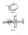
- a suture lock fastening device 1 includes a fastening head 2, a shaft 3, and an actuation handle 4.
- the proximal end of the fastening device or any of its components refers to the part that is in the direction of the handle 4.
- the distal end of the fastening device or any of its components is the part that is in the direction of the fastening head 2.
- Axial or longitudinal movement refers to movement from the proximal end to the distal end or vice versa.
- the fastening head 2 is operatively coupled to the actuation handle 4 via the shaft 3. Operation of the handle 4 actuates the fastening head 2 so as to fasten a suture lock onto a suture and thereby cinch or lock the suture.
- the fastening head 2 includes a body 20 that is configured to support a suture lock that includes a suture lock ring 21 and a suture lock plug 22.
- a retainer 23 is supported at a distal end of the body to maintain the suture lock within the fastening head as the suture lock is fastened to secure a suture.
- a cutter 24 is movably supported within the body to sever the suture.
- a driver 26 is movably supported within the body to drive the suture lock plug 22 into the suture lock ring 21 to cinch the suture.
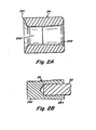
- the body 20 may be configured to have a substantially cylindrical shape with a chamber 200 for receiving the suture lock components 21, 22, the cutter 24 and the driver 26.
- the body 20 includes a lip 201 at its distal end that extends radially inward toward the center of the body 20.
- the lip 201 may be configured to act as a stop to maintain the fastening head components within the body after the suture lock has been deployed from the fastening head 2.
- the body 20 may be provided with a suture opening 202 along at least a portion of the body wall to allow passage of a suture therethrough.
- the suture opening 202 may be configured to permit at least a single suture strand to pass through without substantially compressing or stressing the suture.
- the suture opening 202 is configured as a slot that is dimensioned to permit several strands of suture to pass through without substantially compressing or stressing the suture.
- the suture lock ring 21 may include a distal portion that is configured to protrude from the distal end of the body 20 when the ring is loaded into the fastening head.
- the retainer 23 is configured to extend across at least a portion of a distal end of the suture lock ring to maintain the ring within the fastening head 2. In this manner, the retainer 23 holds the suture lock ring 21 in the body 20 of the fastening head 2 as the suture lock plug 22 is being inserted into the ring 21 during the fastening operation.
- the retainer 23 is configured to release the suture lock from the fastening head 2 upon application of a predetermined release force.
- the retainer 23 is configured to irreversibly deform in response to the release force to a deformed configuration that permits deployment of the suture lock from the fastening head 2.
- the retention capability of the retainer has been substantially reduced so that the deformed retainer is no longer capable of providing adequate retention force that would allow another suture lock to be secured onto a suture.
- Irreversible deformation of the retainer may involve, but is not limited to, expanding, stretching, tearing, rupturing and/or shearing of the retainer.
- the retainer is configured to release the suture lock in response to the application of a release force against the retainer by the suture lock ring.
- the retainer 23 engages and holds the suture lock ring 21 in the distal end of the body 20.
- Various factors that may be considered in determining the retention and release forces of the retainer include, but are not limited to, the force required to insert the plug 22 into the ring 21 to secure a suture and the force that can be readily and comfortably generated by a person's hand to release the suture lock from the fastening head. If the release force of the retainer is too low, the plug 22 and ring 21 may not adequately secure the suture 50 before the lock is released from the body 20. However, if the release force is too high, it may be difficult for a user to release the suture lock from the fastening head 2.
- the retainer 23 is configured to have a release force of approximately 3.6 to 6.8Kg (8 to 15 lbs). In another embodiment, the retainer is configured to have a release force of approximately 4.5 to 5.4Kg (10 to 12 lbs). However, it is to be appreciated that the retainer may be configured to provide any desirable retention and/or release forces as would be apparent to one of skill in the art.
- the retention and release forces of the retainer 23 may be affected by one or more factors that may include, but are not limited to, material properties, material thickness, and/or the structural characteristics of the retainer.
- the retainer 23 may be formed of a material that provides various characteristics including, but not limited to, strength, elasticity, conformability, biological inertness and/or lubricity.
- the retainer 23 is formed of a polymer material, such as polyester, having a thickness of approximately 0.051mm (0.002 inches). It is to be appreciated, however, that the retainer may be formed from other suitable materials, including polymers, elastomers, metals, or combinations thereof, as would be apparent to one of skill in the art.
- the retainer 23 has a sleeve or tubular configuration that is configured to substantially cover the body 20.
- An opening 230 may be aligned with the suture slot 202 in the body 20 to provide for egress of a suture 50.
- the retainer 23 may have a length that is greater than the body 20 with a portion of the retainer 23 extending beyond the distal end of the body 20 to form a lip or flange-like structure 231 that overlies and engages the distal end of suture lock ring 21.
- the lip 231 retains the ring 21 within the body 20 and prevents premature deployment of the suture lock from the fastening head 2.
- a portion of the retainer 23 may also extend beyond the proximal end of the body 20 to form a proximal lip or flange-like structure 232 that overlies and engages the proximal end of the body to thereby secure the retainer 23 to the body 20.
- the proximal lip 232 retards axial movement of the retainer across the body when the distal portion 231 of the retainer subjected to forces applied through the suture lock ring. This arrangement ensures that the retainer 23 will maintain the suture lock within the fastening head during the fastening process.
- the retainer 23 is configured to closely conform to the shape of the underlying components, including the body 20 and the suture lock ring 21.
- the retainer 23 may be formed from a shrink tube or sleeve that shrinks about and conforms to the body upon the application of heat or by using another suitable process.
- the retainer employs a polyester shrink tube having a wall thickness of approximately 0.051mm (0.002 inches), as available from Advanced Polymerics Inc.
- suitable shrink tubes may be used as would be apparent to one of skill in the art.
- the retainer may employ other irreversibly deformable configurations for retaining the suture lock as it is being secured to a suture and then releasing the suture lock after it is secured to the suture.
- the retainer 23 includes a retention pin 233 that couples the suture lock ring 21 to the body 20.
- the retention pin 233 acts to prevent the suture lock ring 21 from moving axially with respect to the body 20.
- the pin 233 protrudes through and cooperates with a corresponding retention hole 234 in the wall of the body 20.
- the retention pin 233 may extend entirely through the retention hole 234 to reduce the potential for the pin to be inadvertently released from the body 20.
- the retention pin 233 is formed as an integral part of the ring 21.
- the pin may be a separate component that interlocks the ring 21 to the body 20.
- the pin 233 may be configured to deform at a predetermined release force. In one embodiment, a portion of the pin 233 may be sheared off or otherwise deform to release the ring 21 from the fastening head 2 when the ring 21 is subjected to the release force. The pin 233 may be configured to shear or deform at a predetermined location.
- the body 20 and/or the retainer 23 may be configured to tear or rupture to release the suture lock.
- the body 20 may be configured with a tear or rupture zone that is located distal to the pin 233 so that the pin 233 tears through the body 20 when the ring 21 is subjected to the release force.
- Other configurations which require an irreversible deformation of the fastening device to release a suture lock from the fastening device could additionally or alternatively be used.
- the fastening head 2 may also include a cutter 24 to sever the suture.
- the cutter 24 is supported for axial movement within the chamber 200 of the body 20.
- the cutter 24 may have an outer diameter that corresponds closely to the inner diameter of the body 20 to maintain axial alignment of the cutter with the suture lock components while allowing axial movement of the cutter within the body.
- the cutter 24 includes a sharp cutting surface or edge 241 along the outer distal edge of the cutter.
- the cutting edge 241 may extend around the entire outer diameter of the cutter 24.
- the cutting edge 241 does not need to extend around the entire outer perimeter of the cutter 24 and may be limited to a portion of the cutter that sevèrs the suture.
- the sharp cutting surface 241 may extend only around the portion of the cutter 24 aligned with the suture slot 202 in the body 20.
- the suture slot 202 may also include a sharp edge 203 on its distal inner edge which may be configured for use in conjunction with the cutter 24 to sever a portion of the suture extending through the slot.
- a sharp edge 203 on its distal inner edge which may be configured for use in conjunction with the cutter 24 to sever a portion of the suture extending through the slot.
- the cutter 24 may be configured to movably support the suture lock plug.
- the cutter 24 includes a center bore 240 that extends axially therethrough.
- the cutter is configured to slidably receive the suture lock plug 22 within the bore for axial movement relative to the cutter.
- the bore may have an inner diameter that corresponds closely to the outer diameter of the plug 22 to maintain axial alignment of the plug with the cutter and the ring while allowing axial movement of the plug along the cutter.
- a proximal portion 242 of the bore 240 may have a tapered configuration that decreases in the axial direction from the proximal end toward the distal end of the cutter 24.
- the tapered portion 242 of the bore provides a way to axially move the cutter 24 only when desired.
- the cutter 24 may be designed to move axially only after the plug 22 supported therein has been displaced a predetermined distance.
- the frictional force between the cutter 24 and body 20 may be greater than the frictional force between the cutter 24 and the plug 22.
- the relatively low frictional force between the plug 22 and the cutter 24 may be created with a relatively loose fit between the components and/or employing materials having relatively low frictional properties.
- a larger frictional force between the cutter 24 and the body 20 will result in moving the plug 22 with respect to the cutter 24 in response to an axial force without also moving the cutter 24 within the body 20.
- an adhesive or a fixation device such as a pin, a lip, or a detent, may be used to retard movement of the cutter 24 relative to the body 20.
- the cutter 24 is formed from 304 stainless steel.
- the cutter may be formed from other suitable materials, such as metals, polymers, and combinations thereof.
- the cutting edge 241 may be formed of a metal, while the remainder of the cutter may be formed from a different material, such as a plastic material.
- the driver 26 is supported in the body 20 proximal to cutter 24 and the suture lock components.
- the driver 26 includes a driver head with a distal portion 262 that is configured to engage and drive the suture lock plug 22 from the cutter 24 and into the suture lock ring 21 and a proximal portion 264 that is configured to engage and drive the cutter 24.
- the distal portion 262 may have a solid cylindrical shape of approximately the same diameter as the plug 22 so that the driver can distribute forces across the end of the plug while being driven through the cutter.
- the proximal portion 264 may have a tapered shape that corresponds to the tapered portion 242 of the bore 240 of the cutter 24. It is to be understood, however, that the driver 26 may employ other suitable configurations as would be apparent to one of skill in the art.
- the driver 26 is coupled to the actuation handle 4 via a drive wire 30 which extends along and is a component of the shaft 3.
- the drive wire 30 transfers movement of the actuation handle 4 to the fastening head 2.
- a distal end of the drive wire 30 mates with a counterbore in the proximal end of the driver 26.
- the drive wire 30 may be configured to withstand compressive axial force without significant deformation yet be relatively flexible so that the fastening device may be flexed as necessary.
- the drive wire 30 is formed of a flexible stainless steel wire.
- the drive wire need not be flexible and may be a relatively rigid structure, for example, if a rigid fastening device is desired.
- the fastening head 2 includes a sleeve adapter 25 that is supported at the proximal end of the body 20.
- the sleeve adapter 25 is substantially cylindrical and has a central bore 250 that supports the driver 26 in axial alignment with the plug 22 and the cutter 24.
- the proximal end of the bore 250 forms an abutment or stop 251 that engages the proximal end of the driver 26 to prevent the driver 26 from being retracted proximally out of the fastening head 2.
- the outer diameter of the sleeve adapter 25 corresponds closely to the inner diameter of the body 20.
- the sleeve adapter 25 may be fastened or adhered to the body 20 so that the sleeve adapter 25 cannot move axially relative to the body 20.
- the sleeve adapter 25 is integrally formed with the body 20 as a single piece.
- the sleeve adapter 25 is formed from 304 stainless steel. However, it is to be appreciated that the sleeve adapter may be formed from other suitable materials as would be apparent to one of skill in the art.
- the suture lock includes a suture lock ring 21 and a suture lock plug 22 that is insertable into the ring to cinch a suture therebetween.
- the ring and plug are supported by the body and may be preloaded into the fastening head 2.
- the ring 21 may have a substantially cylindrical shape with a center bore extending axially therethrough.
- the ring includes a proximal portion that is configured to be inserted into the distal end of the body and an enlarged distal portion that is configured to protrude from the distal end of the body.
- the distal portion of the ring forms a lip 210 that engages the distal end of the body to prevent the ring 21 from being pushed back into the fastening head 2.
- the distal portion may include a tapered outer face 211 to facilitate distal movement of the ring 21 which may help eject the suture lock from the fastening head 2. It is to be appreciated that the ring may employ other suitable configurations as would be apparent to one of skill in the art.
- the suture lock plug 22 may have a substantially cylindrical shape that is configured to be inserted into the ring.
- the plug 22 includes a tapered distal end 220 to facilitate insertion of the plug 22 into the bore 212 of the ring 21. It is to be appreciated that the plug may have other suitable configurations as would be apparent to one of skill in the art.
- the ring 21 and plug 22 may be formed from any suitable material, including metals, polymers or plastics.
- the ring 21 and the plug 22 are formed from a polymer, such a polyetheretherketone (PEEK).
- PEEK polyetheretherketone
- the ring and the plug may be formed from other suitable materials apparent to one of skill in the art.
- the shaft 3 includes a sleeve 40 with an inner passage through which extends the drive wire 30.
- the sleeve 40 connects the fastening head 2 to the actuation handle 4 in a manner that permits axial movement of the drive wire 30 therethrough to actuate the fastening head.
- the sleeve 40 includes an outer sleeve 40a and an inner sleeve 40b concentrically disposed within the outer sleeve.
- the inner and outer sleeves provide the shaft with one or more desirable properties or characteristics.
- the outer sleeve 40a may provide the shaft 3 with lubricity and the inner sleeve 40b may provide the shaft 3 with strength and flexibility.
- the outer sleeve 40a is formed from a polymer or elastomer, such as PEBAX, and the inner sleeve 40b is formed form a stainless steel hypotube.
- the sleeves may be formed of other suitable materials as would be apparent to one of skill in the art.
- the shaft 3 may have any length suitable for the intended application for the fastening device 1. In one illustrative embodiment for use in endoscopic bariatric surgery, the shaft 3 should have sufficient length that is capable of extending from outside the patient to desired regions of a patient's stomach.
- the fastening device 1 includes a positioning sleeve 31 that is configured to engage a corresponding feature of an endoscope to position the fastening head 2 at a desired location relative to the endoscope.
- the positioning sleeve 31 may have any shape or configuration that is suitable to engage the corresponding feature on the endoscope or other instrument employed during the surgical procedure.
- the actuation handle 4 includes a grip 41 and an actuator 42 that is movably supported on the grip.
- the actuator 42 is coupled to the drive wire 30 so that axial movement of the actuator 42 causes corresponding movement of the drive wire 30.
- axial movement of the drive wire in the distal direction actuates driver 26 within the fastening head 2 to fasten and release the suture lock.
- the grip 41 and actuator 42 are shown to have a particular configuration, it is to be appreciated that the grip 41 and the actuator 42 may have any suitable configuration that allows a user to grasp the fastening device 1 and actuate the actuator 42 relative to the grip 41.
- the grip 41 may be configured to be easily held by a user and allow a user to counteract a force placed on the actuator 42.
- the grip has a T-handle configuration and the actuator is configured as a plunger with a rounded head at its proximal end.
- the grip and the actuator may employ other suitable configurations as would be apparent to one of skill in the art.
- the drive wire 30 and the sleeve 40 may be secured to the handle using various insert supports.
- the drive wire 30 is attached to the distal end of the actuator 42 using a drive wire support 43 that acts as a bushing to maintain the drive wire centered in the actuator and reduces the potential for the drive wire to buckle.
- the inner sleeve 40b is attached to the grip 41 using a handle insert 44 that acts as an interface between the metal hypotube and the relatively softer plastic material which may be used to form the handle. It is to be appreciated that other connection arrangements may be employed to attach the handle to the various components of the fastening device as would be apparent to one of skill in the art.
- the components of the fastening device 1 have been described as having cylindrical shapes with cylindrical inner bores. However, it is to be understood that the components may employ other shapes, either externally or internally.
- the bore of one component such as the body 20
- the bore of one component could be non-circular (e.g., ellipsoid or polygonal) and the outer surfaces of other components, such as the sleeve adapter 25, the driver head 26, the cutter 24 and/or suture lock ring 21 could have a corresponding non-circular cross sectional shape.
- the suture lock plug 22 could have a non-circular cross sectional shape and the inner bore of the cutter 24 and the suture lock ring 21 could have a corresponding non-circular cross sectional shape.
- a surgical procedure may be performed on a patient using a suturing instrument, such as an endoscopic suturing device as disclosed in U.S. Patent Application Publication US 2005/0033319 .
- a suturing instrument such as an endoscopic suturing device as disclosed in U.S. Patent Application Publication US 2005/0033319 .
- the suturing instrument is removed from the patient so that the sutures may be secured with a suture lock.
- a suture 50 is threaded through the suture lock ring 21, the chamber 200 of the body and out through the suture slot 202.
- the suture lock plug 22 is supported within the body 20 by the cutter 24 and the sleeve adapter 25. As shown, the plug 22 is axially aligned with and spaced proximally to the suture lock ring 21.
- the cutter 24 is located proximal to the suture slot 202 so that there is adequate spacing between the cutting edge 241 of the cutter 24 and the cutting edge 203 of the slot to permit the suture 50 to exit the fastening head 2 through the suture slot 202.
- the fastening head 2 of the fastening device is then advanced along the suture to the surgical site.
- the suture may be pulled taut to facilitate advancement of the fastening device.
- the fastening head 2 is advanced to its desired location, such as when the positioning sleeve 31, if employed, abuts a mating portion of the endoscope.
- FIG. 9 illustrates an initial cinched position for the fastening head 2 in which the suture lock plug has been advanced distally through the cutter 24 and into the proximal end of the suture lock ring 20. This is accomplished by moving the actuator 42 distally relative to the grip 41, with the suture 50 pulled taut, which causes the drive wire 30 and the driver 26 to move distally against the plug 22 and drive the plug distally through the cutter 24. During this initial actuation, only the plug 22 is moved along the body by the driver 26 and the cutter 24 remains in its initial position.
- the tapered surface 261 of the driver 26 engages the mating tapered bore 240 of the cutter 24 to initiate distal movement of the cutter 24.
- FIG. 10 illustrates a final cinched position of the fastening head 2 in which the suture lock plug 22 has been fully advanced into the suture lock ring 21 to cinch the suture.
- application of an axial force on the drive wire 30 causes the tapered surface 261 of the driver 26 to engage and drive the cutter 24 in the distal direction along the body 20 while continuing to drive the plug 22 into the ring 21.
- the cutting edge 241 of the cutter 24 and the cutting edge 203 of the body 20 eventually capture and sever the portion of the suture 50 extending through the suture slot 202.
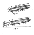
- FIG. 11 illustrates a cut position of the fastening head 2 in which the suture 50 has been completely severed by the cutting edges 203, 241 proximal to the suture lock. The trailing end of the suture 50 may then be removed from the patient.
- FIG. 12 illustrates a deployment position of the fastening head 2 in which the suture lock is deployed. This is accomplished by applying additional axial force on the actuator 42 which results in the suture lock ring 21 exerting a force against the retainer 23. When the force applied against the retainer 23 reaches a predetermined release force, the retainer 23 irreversibly deforms to allow passage of the cinched suture lock from the fastening head. The cutter 24 and the driver 26 are retained in the fastening head 2 by the distal lip 201 on the body 20.
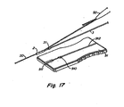
- a suture threading device 90 is provided with the suture lock fastening device to facilitate threading of a suture through the fastening head 2.
- the threading device includes a handle 91 and a suture threader 92.
- the handle 91 is configured to be grasped by a user to support the fastening head 2 as the suture is drawn through the fastening head with the suture threader 92.
- the handle 91 may be detachably mounted to the fastening device 1 so that the handle may be readily removed to facilitate insertion of the fastening device into a patient once the suture has been threaded through the fastening head 2.
- the handle may be configured to snap-fit onto the fastening head 2. It is to be appreciated, however, that other suitable attachment arrangement may be implemented with the handle.
- the suture threader 92 includes a threading loop that may act as a snare to capture the suture.
- the threader 92 extends in a distal direction through the suture slot 202 in the body 20, the suture lock plug 21 and the retainer 23 with the threading loop protruding from the distal end of the fastening head 2.
- the proximal ends of the suture threading loop are connected to a pull tab 93 that provides a grip for pulling the suture threader and the suture through the fastening head.
- the threading loop may include a single loop of flexible wire or other flexible strong material as would be apparent to one of skill in the art.
- the handle 91 includes a base with an elongated channel 912 that is configured to receive the distal portion of the fastening device.
- the base also includes one or more cavities that are configured to mate with particular features or components of the fastening device.
- the base 91 may include a first cavity 910 for the holding the positioning sleeve 31 and a second cavity 911 for holding the fastening head 2.
- the proximal end of the second cavity forms an abutment or stop that is engaged by the proximal end of the fastening head 2 to counteract forces required to pull the suture threader through the fastening head. Supporting the distal end of the fastening device 1 in this manner may facilitate loading the suture.
- the suture threading device 90 may include a fastener, such as a securing tape 94, which helps maintain the distal end of the fastening device 2 within the handle 91.
- a fastener such as a securing tape 94
- the securing tape may not be necessary and that other suitable fastening arrangements may be employed to retain the fastening head within the handle as would be apparent to one of skill in the art.
- FIGS. 14-17 One illustrative embodiment of loading a suture into the fastening head 2 is described below in conjunction with FIGS. 14-17 .
- a suture 50 is threaded through the suture threader 92.
- the pull tab 93 is pulled in the proximal direction relative to the fastening head 2 as shown in FIGS. 15 and 16 .
- This action draws the threader loop and the suture 50 through the distal end of the fastening head and then out through the suture slot 202 in the side of the fastening head.
- the securing tape 94 may be removed, as shown in FIG. 17 , and the handle may be detached from the distal portion of the fastening device. Thereafter, the fastening device may be advanced along the suture to the desired surgical site to secure the suture as described above.
- the handle 91 may facilitate loading of a suture into the fastening device, it is to be appreciated that a handle is not required for each embodiment of the fastening device.
- the suture threader 92 may be used as a stand alone device to thread a suture through the fastening head as described above. Instead of grasping a handle, the user may directly grasp the distal portion of the fastening device as the suture is being pulled through the fastening head.
Landscapes
- Health & Medical Sciences (AREA)
- Life Sciences & Earth Sciences (AREA)
- Surgery (AREA)
- Heart & Thoracic Surgery (AREA)
- Engineering & Computer Science (AREA)
- Biomedical Technology (AREA)
- Nuclear Medicine, Radiotherapy & Molecular Imaging (AREA)
- Medical Informatics (AREA)
- Molecular Biology (AREA)
- Animal Behavior & Ethology (AREA)
- General Health & Medical Sciences (AREA)
- Public Health (AREA)
- Veterinary Medicine (AREA)
- Surgical Instruments (AREA)
Claims (11)
- Fixiervorrichtung für einen Wundnahtverschluss zur Fixierung eines Wundnahtverschlusses, wobei der Wundnahtverschluss einen Wundnahtverschlussring (21) und einen Wundnahtverschlussstopfen (22), der in den Wundnahtverschlussring eingesetzt werden kann, um ein Nahtmaterial zwischen ihnen zu befestigen, beinhaltet, wobei die Fixiervorrichtung für einen Wundnahtverschluss Folgendes aufweist:einen Betätigungsgriff (4) undeinen Fixierkopf (2), der funktionell mit dem Betätigungsgriff gekoppelt ist, wobei der Fixierkopf Folgendes beinhaltet:einen Körper (20), der aufgebaut und angeordnet ist, um den Wundnahtverschlussring und den Wundnahtverschlussstopfen zu tragen, undeinen Halter (23), der aufgebaut und angeordnet ist, um den Wundnahtverschluss im Körper festzuhalten,wobei der Wundnahtverschlussstopfen (22) in den Wundnahtverschlussring (21) eingesetzt werden kann, um dazwischen ein Nahtmaterial zu befestigen, wenn eine Kraft auf den Wundnahtverschlussstopfen (22) ausgeübt wird,dadurch gekennzeichnet, dass der Halter aufgebaut und angeordnet ist, um den Wundnahtverschluss als Reaktion auf eine vorbestimmte Auslösekraft auszulösen, die vom Wundnahtverschlussring (21) direkt auf den Halter (23) ausgeübt wird, wobei die genannte vorbestimmte Auslösekraft größer als die Kraft ist, die auszuüben ist, um den Wundnahtverschlussstopfen (22) in den Wundnahtverschlussring (21) einzusetzen, so dass ein Nahtmaterial zwischen dem Wundnahtverschlussring (21) und dem Wundnahtverschlussstopfen (22) angemessen befestigt ist, bevor der Wundnahtverschluss vom Körper (20) gelöst wird.
- Fixiervorrichtung für einen Wundnahtverschluss nach Anspruch 1, wobei der Halter (23) aufgebaut und angeordnet ist, um sich bei Ausübung der vorbestimmten Kraft zum Lösen des Wundnahtverschlusses (21, 22) zu verformen.
- Fixiervorrichtung für einen Wundnahtverschluss nach Anspruch 2, wobei der Halter (23) aufgebaut und angeordnet ist, so dass er zum Lösen des Wundnahtverschlusses (21, 22) irreversibel verformt wird.
- Fixiervorrichtung für einen Wundnahtverschluss nach Anspruch 3, wobei der Halter (23) eine Schrumpfschlauchhülse mit einem distalen Teil (231), der sich für den Eingriff mit dem Wundnahtverschlussring (21) über ein distales Ende des Körpers (20) hinaus erstreckt.
- Fixiervorrichtung für einen Wundnahtverschluss nach Anspruch 1, wobei der Fixierkopf (2) ein Messer (24) mit einer Schneide (241) beinhaltet, das zum Schneiden eines Nahtmaterials (50) aufgebaut und angeordnet ist.
- Fixiervorrichtung für einen Wundnahtverschluss nach Anspruch 5, wobei das Messer (24) im Körper (20) beweglich gelagert ist.
- Fixiervorrichtung für einen Wundnahtverschluss nach Anspruch 6, wobei das Messer (24) aufgebaut und angeordnet ist, um den Wundnahtverschlussstopfens (22) abzustützen.
- Fixiervorrichtung für einen Wundnahtverschluss nach Anspruch 5, wobei der Fixierkopf (2) einen Treiber (26) beinhaltet, der vom Körper (20) beweglich getragen wird, um den Wundnahtverschluss (21, 22) bei Betätigung des Betätigungsgriffs (4) zu fixieren.
- Fixiervorrichtung für einen Wundnahtverschluss nach Anspruch 1, die ferner einen länglichen Schaft (3) aufweist, der den Betätigungsgriff (4) funktionell mit der Fixiervorrichtung (2) koppelt.
- Fixiervorrichtung für einen Wundnahtverschluss nach Anspruch 9, wobei der Schaft (3) flexibel ist.
- Fixiervorrichtung für einen Wundnahtverschluss nach Anspruch 10, wobei der Schaft (3) wenigstens eine Hülse (40) und einen gleitfähig von der Hülse getragenen Antriebsdraht (30) beinhaltet, wobei der Antriebsdraht zur Betätigung des Fixierkopfs (2) bei Betätigung des Betätigungsgriffs (4) aufgebaut und angeordnet ist.
Applications Claiming Priority (2)
| Application Number | Priority Date | Filing Date | Title |
|---|---|---|---|
| US11/436,398 US8105355B2 (en) | 2006-05-18 | 2006-05-18 | Suture lock fastening device |
| EP07794900A EP2029031B1 (de) | 2006-05-18 | 2007-05-16 | Fixiervorrichtung für wundnahtverschluss |
Related Parent Applications (2)
| Application Number | Title | Priority Date | Filing Date |
|---|---|---|---|
| EP07794900.6 Division | 2007-05-16 | ||
| EP07794900A Division EP2029031B1 (de) | 2006-05-18 | 2007-05-16 | Fixiervorrichtung für wundnahtverschluss |
Publications (2)
| Publication Number | Publication Date |
|---|---|
| EP2397078A1 EP2397078A1 (de) | 2011-12-21 |
| EP2397078B1 true EP2397078B1 (de) | 2014-12-17 |
Family
ID=38569341
Family Applications (2)
| Application Number | Title | Priority Date | Filing Date |
|---|---|---|---|
| EP07794900A Not-in-force EP2029031B1 (de) | 2006-05-18 | 2007-05-16 | Fixiervorrichtung für wundnahtverschluss |
| EP11180293.0A Not-in-force EP2397078B1 (de) | 2006-05-18 | 2007-05-16 | Fixiervorrichtung für Wundnahtverschluss |
Family Applications Before (1)
| Application Number | Title | Priority Date | Filing Date |
|---|---|---|---|
| EP07794900A Not-in-force EP2029031B1 (de) | 2006-05-18 | 2007-05-16 | Fixiervorrichtung für wundnahtverschluss |
Country Status (5)
| Country | Link |
|---|---|
| US (2) | US8105355B2 (de) |
| EP (2) | EP2029031B1 (de) |
| AT (1) | ATE523147T1 (de) |
| ES (2) | ES2371943T3 (de) |
| WO (1) | WO2007136631A2 (de) |
Families Citing this family (128)
| Publication number | Priority date | Publication date | Assignee | Title |
|---|---|---|---|---|
| US7601161B1 (en) | 1999-07-02 | 2009-10-13 | Quick Pass, Inc. | Suturing device |
| US6780198B1 (en) * | 2001-12-06 | 2004-08-24 | Opus Medical, Inc. | Bone anchor insertion device |
| US6984237B2 (en) | 2002-05-22 | 2006-01-10 | Orthopaedic Biosystems Ltd., Inc. | Suture passing surgical instrument |
| US8608797B2 (en) | 2005-03-17 | 2013-12-17 | Valtech Cardio Ltd. | Mitral valve treatment techniques |
| EP1909655A2 (de) * | 2005-06-20 | 2008-04-16 | Sutura, Inc. | Verfahren und gerät zum anbringen eines knotens an einem nahtmaterial |
| US9883943B2 (en) | 2006-12-05 | 2018-02-06 | Valtech Cardio, Ltd. | Implantation of repair devices in the heart |
| US11259924B2 (en) | 2006-12-05 | 2022-03-01 | Valtech Cardio Ltd. | Implantation of repair devices in the heart |
| US8617185B2 (en) * | 2007-02-13 | 2013-12-31 | P Tech, Llc. | Fixation device |
| US11660190B2 (en) | 2007-03-13 | 2023-05-30 | Edwards Lifesciences Corporation | Tissue anchors, systems and methods, and devices |
| JP5411125B2 (ja) | 2007-03-29 | 2014-02-12 | ノーブルズ メディカル テクノロジーズ、インコーポレイテッド | 卵円孔開存を閉鎖するための縫合装置、及びシステム |
| US7963972B2 (en) | 2007-09-12 | 2011-06-21 | Arthrocare Corporation | Implant and delivery system for soft tissue repair |
| US8382829B1 (en) | 2008-03-10 | 2013-02-26 | Mitralign, Inc. | Method to reduce mitral regurgitation by cinching the commissure of the mitral valve |
| US9039682B2 (en) * | 2008-03-14 | 2015-05-26 | Merit Medical Systems, Inc. | Suture securement apparatus |
| US8951270B2 (en) * | 2008-08-29 | 2015-02-10 | Marit Medical Systems, Inc. | Surgical securement system and apparatus |
| US8771296B2 (en) | 2008-05-09 | 2014-07-08 | Nobles Medical Technologies Inc. | Suturing devices and methods for suturing an anatomic valve |
| US8834495B2 (en) | 2008-06-30 | 2014-09-16 | Arthrocare Corporation | Independent suture tensioning and snaring apparatus |
| US8795293B2 (en) * | 2008-09-29 | 2014-08-05 | Karl Storz Gmbh & Co. Kg | Flipp tack pusher |
| US10517719B2 (en) | 2008-12-22 | 2019-12-31 | Valtech Cardio, Ltd. | Implantation of repair devices in the heart |
| US8241351B2 (en) | 2008-12-22 | 2012-08-14 | Valtech Cardio, Ltd. | Adjustable partial annuloplasty ring and mechanism therefor |
| WO2012176195A2 (en) | 2011-06-23 | 2012-12-27 | Valtech Cardio, Ltd. | Closure element for use with annuloplasty structure |
| US8715342B2 (en) | 2009-05-07 | 2014-05-06 | Valtech Cardio, Ltd. | Annuloplasty ring with intra-ring anchoring |
| US8545553B2 (en) | 2009-05-04 | 2013-10-01 | Valtech Cardio, Ltd. | Over-wire rotation tool |
| ES2873182T3 (es) | 2008-12-22 | 2021-11-03 | Valtech Cardio Ltd | Dispositivos de anuloplastia ajustables |
| US8353956B2 (en) | 2009-02-17 | 2013-01-15 | Valtech Cardio, Ltd. | Actively-engageable movement-restriction mechanism for use with an annuloplasty structure |
| US9968452B2 (en) | 2009-05-04 | 2018-05-15 | Valtech Cardio, Ltd. | Annuloplasty ring delivery cathethers |
| US12485010B2 (en) | 2009-05-07 | 2025-12-02 | Edwards Lifesciences Innovation (Israel) Ltd. | Multiple anchor delivery tool |
| US9180007B2 (en) | 2009-10-29 | 2015-11-10 | Valtech Cardio, Ltd. | Apparatus and method for guide-wire based advancement of an adjustable implant |
| US10098737B2 (en) | 2009-10-29 | 2018-10-16 | Valtech Cardio, Ltd. | Tissue anchor for annuloplasty device |
| EP2506777B1 (de) | 2009-12-02 | 2020-11-25 | Valtech Cardio, Ltd. | Kombination von einer Spulenanordnung mit helikalem Anker und einem Verabreichungswerkzeug zur Implantation derselben |
| US8540735B2 (en) * | 2010-12-16 | 2013-09-24 | Apollo Endosurgery, Inc. | Endoscopic suture cinch system |
| US8556916B2 (en) | 2011-02-14 | 2013-10-15 | Smith & Nephew, Inc. | Method and device for suture manipulation |
| EP2696778B1 (de) * | 2011-04-11 | 2020-05-06 | St. Jude Medical Puerto Rico LLC | Nahtfixiervorrichtung |
| EP3644194B1 (de) | 2011-04-15 | 2022-12-07 | Heartstitch, Inc. | Nähvorrichtungen zum nähen einer anatomischen klappe |
| EP2709536B1 (de) * | 2011-05-18 | 2020-06-03 | St. Jude Medical Puerto Rico LLC | Nahtfixiervorrichtung |
| US10792152B2 (en) | 2011-06-23 | 2020-10-06 | Valtech Cardio, Ltd. | Closed band for percutaneous annuloplasty |
| US20130178898A1 (en) * | 2011-07-06 | 2013-07-11 | Imds Corporation | Tissue approximation |
| US8858623B2 (en) | 2011-11-04 | 2014-10-14 | Valtech Cardio, Ltd. | Implant having multiple rotational assemblies |
| EP2775896B1 (de) | 2011-11-08 | 2020-01-01 | Valtech Cardio, Ltd. | Gesteuerte lenkfunktionalität für ein implantatabgabewerkzeug |
| US8968336B2 (en) | 2011-12-07 | 2015-03-03 | Edwards Lifesciences Corporation | Self-cinching surgical clips and delivery system |
| JP6153938B2 (ja) | 2011-12-12 | 2017-06-28 | デイヴィッド・アロン | 心臓弁修復デバイス |
| US9078645B2 (en) | 2011-12-19 | 2015-07-14 | Edwards Lifesciences Corporation | Knotless suture anchoring devices and tools for implants |
| US9078652B2 (en) | 2011-12-19 | 2015-07-14 | Edwards Lifesciences Corporation | Side-entry knotless suture anchoring clamps and deployment tools |
| US9017347B2 (en) | 2011-12-22 | 2015-04-28 | Edwards Lifesciences Corporation | Suture clip deployment devices |
| US9706988B2 (en) | 2012-05-11 | 2017-07-18 | Heartstitch, Inc. | Suturing devices and methods for suturing an anatomic structure |
| US8961594B2 (en) * | 2012-05-31 | 2015-02-24 | 4Tech Inc. | Heart valve repair system |
| US10016193B2 (en) | 2013-11-18 | 2018-07-10 | Edwards Lifesciences Ag | Multiple-firing crimp device and methods for using and manufacturing same |
| US9498202B2 (en) | 2012-07-10 | 2016-11-22 | Edwards Lifesciences Corporation | Suture securement devices |
| US9592048B2 (en) | 2013-07-11 | 2017-03-14 | Edwards Lifesciences Corporation | Knotless suture fastener installation system |
| WO2014052599A1 (en) * | 2012-09-26 | 2014-04-03 | Children's National Medical Center | Anastomosis clipping tool with half-loop clip |
| CA2885354A1 (en) | 2012-09-29 | 2014-04-03 | Mitralign, Inc. | Plication lock delivery system and method of use thereof |
| EP2911594B1 (de) | 2012-10-23 | 2018-12-05 | Valtech Cardio, Ltd. | Gesteuerte lenkfunktionalität für ein implantateinführungswerkzeug |
| WO2014064695A2 (en) | 2012-10-23 | 2014-05-01 | Valtech Cardio, Ltd. | Percutaneous tissue anchor techniques |
| WO2014087402A1 (en) | 2012-12-06 | 2014-06-12 | Valtech Cardio, Ltd. | Techniques for guide-wire based advancement of a tool |
| US9724084B2 (en) | 2013-02-26 | 2017-08-08 | Mitralign, Inc. | Devices and methods for percutaneous tricuspid valve repair |
| US10448946B2 (en) | 2013-03-12 | 2019-10-22 | Apollo Endosurgery Us, Inc. | Endoscopic suture cinch |
| US9788831B2 (en) | 2013-03-12 | 2017-10-17 | Apollo Endosurgery Us, Inc. | Endoscopic suture cinch system with replaceable cinch |
| US10449333B2 (en) | 2013-03-14 | 2019-10-22 | Valtech Cardio, Ltd. | Guidewire feeder |
| US20140277131A1 (en) * | 2013-03-15 | 2014-09-18 | Mimosa Medical, Inc. | Tissue anchoring and deployment systems |
| WO2014152503A1 (en) | 2013-03-15 | 2014-09-25 | Mitralign, Inc. | Translation catheters, systems, and methods of use thereof |
| US9468527B2 (en) | 2013-06-12 | 2016-10-18 | Edwards Lifesciences Corporation | Cardiac implant with integrated suture fasteners |
| EA039866B1 (ru) | 2013-07-02 | 2022-03-22 | Мед-Венче Инвестментс, Ллс | Сшивающее устройство и способ сшивания анатомической структуры |
| US10070857B2 (en) | 2013-08-31 | 2018-09-11 | Mitralign, Inc. | Devices and methods for locating and implanting tissue anchors at mitral valve commissure |
| US10299793B2 (en) | 2013-10-23 | 2019-05-28 | Valtech Cardio, Ltd. | Anchor magazine |
| US10022114B2 (en) | 2013-10-30 | 2018-07-17 | 4Tech Inc. | Percutaneous tether locking |
| WO2015085145A1 (en) | 2013-12-06 | 2015-06-11 | Med-Venture Investments, Llc | Suturing methods and apparatuses |
| US9610162B2 (en) | 2013-12-26 | 2017-04-04 | Valtech Cardio, Ltd. | Implantation of flexible implant |
| EP3134008A1 (de) | 2014-04-24 | 2017-03-01 | Smith&Nephew, Inc. | Nahtdurchführung |
| CN107106157A (zh) | 2014-05-30 | 2017-08-29 | 爱德华兹生命科学公司 | 用于固定缝合线的系统 |
| AU2015275683B2 (en) * | 2014-06-15 | 2019-08-08 | Anchora Medical Ltd. | Apparatus and method for suturing a tissue |
| US10939904B2 (en) * | 2014-07-08 | 2021-03-09 | Lsi Solutions, Inc. | Rotation adapter and receiver for minimally invasive surgical devices |
| US10178993B2 (en) | 2014-07-11 | 2019-01-15 | Cardio Medical Solutions, Inc. | Device and method for assisting end-to-side anastomosis |
| EP3206629B1 (de) | 2014-10-14 | 2021-07-14 | Valtech Cardio, Ltd. | Vorrichtung zur rückhaltung von herzklappensegel |
| CN112263293B (zh) | 2014-12-10 | 2024-08-02 | 爱德华兹生命科学股份公司 | 多次发射固定装置及其使用和制造方法 |
| CN107106162B (zh) | 2014-12-24 | 2020-10-27 | 爱德华兹生命科学公司 | 缝合夹部署装置 |
| US20160256269A1 (en) | 2015-03-05 | 2016-09-08 | Mitralign, Inc. | Devices for treating paravalvular leakage and methods use thereof |
| US10470759B2 (en) | 2015-03-16 | 2019-11-12 | Edwards Lifesciences Corporation | Suture securement devices |
| CN114515173B (zh) | 2015-04-30 | 2025-01-28 | 爱德华兹生命科学创新(以色列)有限公司 | 瓣膜成形术技术 |
| EP3397207B1 (de) | 2015-12-30 | 2026-04-01 | Edwards Lifesciences Corporation | System zur reduzierung von triskupidalklappenregurgitation |
| GB2547915B (en) * | 2016-03-02 | 2018-05-23 | Cook Medical Technologies Llc | Medical Filament delivery apparatus |
| WO2017180092A1 (en) | 2016-04-11 | 2017-10-19 | Nobles Medical Technologies Ii, Inc. | Suture spools for tissue suturing device |
| US10702274B2 (en) | 2016-05-26 | 2020-07-07 | Edwards Lifesciences Corporation | Method and system for closing left atrial appendage |
| GB201611910D0 (en) | 2016-07-08 | 2016-08-24 | Valtech Cardio Ltd | Adjustable annuloplasty device with alternating peaks and troughs |
| US10939905B2 (en) | 2016-08-26 | 2021-03-09 | Edwards Lifesciences Corporation | Suture clips, deployment devices therefor, and methods of use |
| CA3036515A1 (en) * | 2016-09-09 | 2018-03-15 | Terumo Medical Corporation | System for suture trimming |
| WO2018081374A1 (en) | 2016-10-31 | 2018-05-03 | Smith & Nephew, Inc. | Suture passer and grasper instrument and method |
| CA3043673A1 (en) | 2016-11-13 | 2018-05-17 | Anchora Medical Ltd. | Minimally-invasive tissue suturing device |
| US10863980B2 (en) | 2016-12-28 | 2020-12-15 | Edwards Lifesciences Corporation | Suture fastener having spaced-apart layers |
| CN110325126B (zh) | 2017-02-22 | 2022-09-20 | 波士顿科学国际有限公司 | 基于缝合的封闭装置 |
| US11045627B2 (en) | 2017-04-18 | 2021-06-29 | Edwards Lifesciences Corporation | Catheter system with linear actuation control mechanism |
| EP3641660B1 (de) | 2017-06-19 | 2024-11-20 | Heartstitch, Inc. | Nähvorrichtungen zum nähen einer öffnung auf der herzspitze |
| WO2018236766A1 (en) | 2017-06-19 | 2018-12-27 | Heartstitch, Inc. | SUTURE SYSTEMS AND METHODS FOR SUITURING BODY TISSUE |
| EP3668415B1 (de) | 2017-08-18 | 2023-10-25 | Nobles Medical Technologies II, Inc. | Vorrichtung zum aufbringen eines knotens auf einer naht |
| US10835221B2 (en) | 2017-11-02 | 2020-11-17 | Valtech Cardio, Ltd. | Implant-cinching devices and systems |
| US11135062B2 (en) | 2017-11-20 | 2021-10-05 | Valtech Cardio Ltd. | Cinching of dilated heart muscle |
| CN116531147A (zh) | 2018-01-24 | 2023-08-04 | 爱德华兹生命科学创新(以色列)有限公司 | 瓣环成形术结构的收缩 |
| EP3743014B1 (de) | 2018-01-26 | 2023-07-19 | Edwards Lifesciences Innovation (Israel) Ltd. | Techniken zur erleichterung von herzklappen-tethering und sehnenaustausch |
| CN112188869B (zh) * | 2018-05-25 | 2025-01-21 | 波士顿科学国际有限公司 | 用于将卡箍件应用于缝合线的设备及方法 |
| US11375993B2 (en) | 2018-06-19 | 2022-07-05 | Boston Scientific Scimed, Inc. | Endoscopic handle attachment for use with suture based closure device |
| CN112638284A (zh) | 2018-06-27 | 2021-04-09 | 波士顿科学国际有限公司 | 与基于缝合线的闭合装置一起使用的内窥镜附接机构 |
| JP7387731B2 (ja) | 2018-07-12 | 2023-11-28 | エドワーズ ライフサイエンシーズ イノベーション (イスラエル) リミテッド | 弁輪形成システムおよびそのための係止ツール |
| IT201800007518A1 (it) * | 2018-07-26 | 2020-01-26 | Medacta Int Sa | Dispositivo di taglio |
| CN120324048A (zh) | 2018-09-06 | 2025-07-18 | 波士顿科学国际有限公司 | 内窥镜式缝合针和缝合线组件附接方法 |
| EP4582011A3 (de) | 2019-05-16 | 2025-08-20 | Boston Scientific Scimed, Inc. | Verschlussvorrichtung auf nahtbasis zur verwendung mit einem endoskop |
| BR112021023706A2 (pt) | 2019-05-29 | 2022-03-22 | Valtech Cardio Ltd | Sistemas e métodos de manuseio de ancoragem de tecido |
| US11523815B2 (en) * | 2019-06-13 | 2022-12-13 | Smith & Nephew, Inc. | Side-loading knot cutter |
| WO2021011522A1 (en) | 2019-07-16 | 2021-01-21 | Lau Jan R | Tissue remodeling systems and methods |
| US12364606B2 (en) | 2019-07-23 | 2025-07-22 | Edwards Lifesciences Innovation (Israel) Ltd. | Fluoroscopic visualization of heart valve anatomy |
| JP7592647B2 (ja) | 2019-07-23 | 2024-12-02 | エドワーズ ライフサイエンシーズ イノベーション (イスラエル) リミテッド | 弁形成構造の収縮 |
| WO2021038560A1 (en) | 2019-08-28 | 2021-03-04 | Valtech Cardio, Ltd. | Low-profile steerable catheter |
| CA3143225A1 (en) | 2019-08-30 | 2021-03-04 | Valtech Cardio, Ltd. | Anchor channel tip |
| KR20220066398A (ko) | 2019-09-25 | 2022-05-24 | 카디악 임플란츠 엘엘씨 | 심장 판막 고리 감소 시스템 |
| WO2021084407A1 (en) | 2019-10-29 | 2021-05-06 | Valtech Cardio, Ltd. | Annuloplasty and tissue anchor technologies |
| KR20220144380A (ko) | 2020-02-18 | 2022-10-26 | 보스톤 싸이엔티픽 싸이메드 인코포레이티드 | 내시경과 함께 사용하기 위한 봉합 기반 폐쇄 디바이스 |
| JP7477624B2 (ja) | 2020-02-19 | 2024-05-01 | ボストン サイエンティフィック サイムド,インコーポレイテッド | 複数の安全限界を備えた高出力アテレクトミー |
| WO2021202508A1 (en) | 2020-03-31 | 2021-10-07 | Boston Scientific Scimed, Inc. | Suture based closure device |
| US12023247B2 (en) | 2020-05-20 | 2024-07-02 | Edwards Lifesciences Corporation | Reducing the diameter of a cardiac valve annulus with independent control over each of the anchors that are launched into the annulus |
| CN115916069A (zh) | 2020-06-19 | 2023-04-04 | 爱德华兹生命科学创新(以色列)有限公司 | 自停式组织锚固件 |
| US11660092B2 (en) * | 2020-09-29 | 2023-05-30 | Covidien Lp | Adapter for securing loading units to handle assemblies of surgical stapling instruments |
| EP4236837A1 (de) | 2020-10-30 | 2023-09-06 | Boston Scientific Scimed, Inc. | Atherektomiegrate mit blutflussverbesserungen |
| EP4649896A3 (de) | 2021-04-26 | 2025-12-10 | Boston Scientific Scimed, Inc. | Verschlussvorrichtung auf nahtbasis |
| CN117500424A (zh) | 2021-04-26 | 2024-02-02 | 波士顿科学国际有限公司 | 基于缝线的闭合装置 |
| EP4649914A3 (de) | 2021-08-16 | 2026-01-28 | Boston Scientific Scimed, Inc. | Atherektomiesystem mit wiederverwendbarem teil und einwegteil |
| CN114073554B (zh) * | 2022-01-19 | 2022-04-15 | 江苏泰科博曼医疗器械有限公司 | 微创手术缝合线端部锁结装置、方法及操作枪体 |
| CN115399821B (zh) * | 2022-06-27 | 2025-07-22 | 瀚芯医疗科技(深圳)有限公司 | 一种锁结装置及手柄控制系统 |
| CN120152668A (zh) | 2022-09-08 | 2025-06-13 | 全球心脏瓣膜创新中心(以色列)有限公司 | 缝合闭合装置 |
| WO2024118934A2 (en) | 2022-12-01 | 2024-06-06 | Boston Scientific Scimed, Inc. | Suture based closure device |
| JP2025540120A (ja) * | 2022-12-06 | 2025-12-11 | ボストン サイエンティフィック サイムド,インコーポレイテッド | 低侵襲処置中に縫合糸を切断するための医療デバイス |
| CN117017382B (zh) * | 2023-09-28 | 2024-09-03 | 运医之星(上海)科技有限公司 | 一种线环的制造方法 |
Family Cites Families (148)
| Publication number | Priority date | Publication date | Assignee | Title |
|---|---|---|---|---|
| US4379358A (en) * | 1981-07-30 | 1983-04-12 | Itw-Ateco Gmbh | Cord adjusters |
| US4455717A (en) * | 1982-09-22 | 1984-06-26 | Gray Robert C | Rope clamping device |
| US5037433A (en) | 1990-05-17 | 1991-08-06 | Wilk Peter J | Endoscopic suturing device and related method and suture |
| US5116349A (en) | 1990-05-23 | 1992-05-26 | United States Surgical Corporation | Surgical fastener apparatus |
| US5593425A (en) * | 1990-06-28 | 1997-01-14 | Peter M. Bonutti | Surgical devices assembled using heat bonable materials |
| US5725529A (en) | 1990-09-25 | 1998-03-10 | Innovasive Devices, Inc. | Bone fastener |
| JP2545558Y2 (ja) | 1990-10-23 | 1997-08-25 | ジョンソン・エンド・ジョンソンメディカル株式会社 | 深部縫合器 |
| US5217472A (en) | 1991-05-07 | 1993-06-08 | United States Surgical Corporation | Surgical fastening device |
| FR2682867A1 (fr) | 1991-10-29 | 1993-04-30 | Nouaille Jean Marc | Procede et dispositif pour bloquer un fil en cóoeliochirurgie. |
| US6001104A (en) | 1991-12-03 | 1999-12-14 | Boston Scientific Technology, Inc. | Bone anchor implantation device |
| WO1993010715A2 (en) | 1991-12-03 | 1993-06-10 | Vesitec Medical, Inc. | Surgical treatment of stress urinary incontinence |
| US5439467A (en) | 1991-12-03 | 1995-08-08 | Vesica Medical, Inc. | Suture passer |
| US5766221A (en) | 1991-12-03 | 1998-06-16 | Boston Scientific Technology, Inc. | Bone anchor implantation device |
| JP3192147B2 (ja) | 1991-12-03 | 2001-07-23 | ボストン サイエンティフィック アイルランド リミテッド,バーバドス ヘッド オフィス | 骨アンカー挿入装置 |
| GB9218754D0 (en) | 1992-09-04 | 1992-10-21 | Univ London | Device for use in securing a thread |
| CA2106236A1 (en) | 1992-09-23 | 1994-03-24 | Jude S. Sauer | Apparatus and method for anchoring surgical instrumentation |
| US5383905A (en) | 1992-10-09 | 1995-01-24 | United States Surgical Corporation | Suture loop locking device |
| DE4240533C1 (de) | 1992-11-27 | 1994-04-07 | Ethicon Gmbh | Endoskopische Schlinge mit Applizierinstrument |
| US5417699A (en) | 1992-12-10 | 1995-05-23 | Perclose Incorporated | Device and method for the percutaneous suturing of a vascular puncture site |
| US5814073A (en) | 1996-12-13 | 1998-09-29 | Bonutti; Peter M. | Method and apparatus for positioning a suture anchor |
| US5562687A (en) | 1993-07-12 | 1996-10-08 | Mitek Surgical Products, Inc. | Surgical repair kit and its method of use |
| US6629984B1 (en) | 1998-07-07 | 2003-10-07 | Kwan-Ho Chan | Surgical repair kit and its method of use |
| US5405354A (en) | 1993-08-06 | 1995-04-11 | Vance Products Inc. | Suture driver |
| US5536273A (en) | 1993-12-09 | 1996-07-16 | Lehrer; Theodor | Apparatus and method of extracorporeally applying and locking laparoscopic suture and loop ligatures |
| US5609597A (en) | 1993-12-09 | 1997-03-11 | Lehrer; Theodor | Apparatus and method of extracorporeally applying and locking laparoscopic suture and loop ligatures |
| USRE36289E (en) | 1993-12-13 | 1999-08-31 | Ethicon, Inc. | Umbrella shaped suture anchor device with actuating ring member |
| US5545180A (en) | 1993-12-13 | 1996-08-13 | Ethicon, Inc. | Umbrella-shaped suture anchor device with actuating ring member |
| US5618314A (en) | 1993-12-13 | 1997-04-08 | Harwin; Steven F. | Suture anchor device |
| US5501692A (en) | 1994-01-28 | 1996-03-26 | Riza; Erol D. | Laparoscopic suture snare |
| US5391173A (en) | 1994-02-10 | 1995-02-21 | Wilk; Peter J. | Laparoscopic suturing technique and associated device |
| US5520702A (en) | 1994-02-24 | 1996-05-28 | United States Surgical Corporation | Method and apparatus for applying a cinch member to the ends of a suture |
| CA2141911C (en) | 1994-02-24 | 2002-04-23 | Jude S. Sauer | Surgical crimping device and method of use |
| US5364407A (en) | 1994-03-21 | 1994-11-15 | Poll Wayne L | Laparoscopic suturing system |
| US5411523A (en) * | 1994-04-11 | 1995-05-02 | Mitek Surgical Products, Inc. | Suture anchor and driver combination |
| US5630824A (en) | 1994-06-01 | 1997-05-20 | Innovasive Devices, Inc. | Suture attachment device |
| US5462558A (en) | 1994-08-29 | 1995-10-31 | United States Surgical Corporation | Suture clip applier |
| US5649963A (en) * | 1994-11-10 | 1997-07-22 | Innovasive Devices, Inc. | Suture anchor assembly and methods |
| US5643321A (en) * | 1994-11-10 | 1997-07-01 | Innovasive Devices | Suture anchor assembly and methods |
| US5665109A (en) | 1994-12-29 | 1997-09-09 | Yoon; Inbae | Methods and apparatus for suturing tissue |
| US5695505A (en) | 1995-03-09 | 1997-12-09 | Yoon; Inbae | Multifunctional spring clips and cartridges and applicators therefor |
| US5630825A (en) | 1995-04-27 | 1997-05-20 | De La Torre; Roger A. | Magazine for loading a needle onto a stitching instrument and for loading a length of suture onto a suture dispensing instrument |
| US6086608A (en) * | 1996-02-22 | 2000-07-11 | Smith & Nephew, Inc. | Suture collet |
| US5935149A (en) | 1995-06-07 | 1999-08-10 | Smith & Nephew Inc. | Suturing tissue |
| US5735877A (en) | 1996-02-28 | 1998-04-07 | Pagedas; Anthony C. | Self locking suture lock |
| US5817111A (en) | 1996-03-28 | 1998-10-06 | Riza; Erol D. | Open loop suture snare |
| US5961538A (en) * | 1996-04-10 | 1999-10-05 | Mitek Surgical Products, Inc. | Wedge shaped suture anchor and method of implantation |
| JP4136020B2 (ja) | 1996-04-17 | 2008-08-20 | オリンパス株式会社 | 医療用結紮具 |
| US6126677A (en) | 1996-05-20 | 2000-10-03 | Noknots Group Inc. | Suture fastener and instrument |
| US6007567A (en) | 1996-08-19 | 1999-12-28 | Bonutti; Peter M. | Suture anchor |
| US5718717A (en) | 1996-08-19 | 1998-02-17 | Bonutti; Peter M. | Suture anchor |
| US5948001A (en) | 1996-10-03 | 1999-09-07 | United States Surgical Corporation | System for suture anchor placement |
| CA2217406C (en) | 1996-10-04 | 2006-05-30 | United States Surgical Corporation | Suture anchor installation system with disposable loading unit |
| US5948002A (en) | 1996-11-15 | 1999-09-07 | Bonutti; Peter M. | Apparatus and method for use in positioning a suture anchor |
| CA2280757A1 (en) | 1997-02-13 | 1998-08-20 | William Pintauro | Method and apparatus for minimally invasive pelvic surgery |
| US5935129A (en) * | 1997-03-07 | 1999-08-10 | Innovasive Devices, Inc. | Methods and apparatus for anchoring objects to bone |
| US5902321A (en) * | 1997-07-25 | 1999-05-11 | Innovasive Devices, Inc. | Device and method for delivering a connector for surgically joining and securing flexible tissue repair members |
| US20050216059A1 (en) | 2002-09-05 | 2005-09-29 | Bonutti Peter M | Method and apparatus for securing a suture |
| US6010525A (en) | 1997-08-01 | 2000-01-04 | Peter M. Bonutti | Method and apparatus for securing a suture |
| US6159234A (en) | 1997-08-01 | 2000-12-12 | Peter M. Bonutti | Method and apparatus for securing a suture |
| US6475230B1 (en) | 1997-08-01 | 2002-11-05 | Peter M. Bonutti | Method and apparatus for securing a suture |
| US5944739A (en) | 1998-03-12 | 1999-08-31 | Surgical Dynamics, Inc. | Suture anchor installation system |
| US6786913B1 (en) | 1999-02-01 | 2004-09-07 | Onux Medical, Inc. | Surgical suturing instrument and method of use |
| US6332889B1 (en) | 1998-08-27 | 2001-12-25 | Onux Medical, Inc. | Surgical suturing instrument and method of use |
| US6200329B1 (en) | 1998-08-31 | 2001-03-13 | Smith & Nephew, Inc. | Suture collet |
| US6306159B1 (en) | 1998-12-23 | 2001-10-23 | Depuy Orthopaedics, Inc. | Meniscal repair device |
| ATE324072T1 (de) | 1998-12-30 | 2006-05-15 | Ethicon Inc | Fadensicherungsgerät |
| US6165204A (en) | 1999-06-11 | 2000-12-26 | Scion International, Inc. | Shaped suture clip, appliance and method therefor |
| US6527785B2 (en) | 1999-08-03 | 2003-03-04 | Onux Medical, Inc. | Surgical suturing instrument and method of use |
| US6767352B2 (en) | 1999-08-03 | 2004-07-27 | Onux Medical, Inc. | Surgical suturing instrument and method of use |
| US6511489B2 (en) | 1999-08-03 | 2003-01-28 | Frederic P. Field | Surgical suturing instrument and method of use |
| US6527794B1 (en) * | 1999-08-10 | 2003-03-04 | Ethicon, Inc. | Self-locking suture anchor |
| US6942674B2 (en) | 2000-01-05 | 2005-09-13 | Integrated Vascular Systems, Inc. | Apparatus and methods for delivering a closure device |
| ES2532327T3 (es) * | 2000-03-03 | 2015-03-26 | C. R. Bard, Inc. | Clip de sutura |
| US7993368B2 (en) * | 2003-03-13 | 2011-08-09 | C.R. Bard, Inc. | Suture clips, delivery devices and methods |
| US7094251B2 (en) | 2002-08-27 | 2006-08-22 | Marctec, Llc. | Apparatus and method for securing a suture |
| US7329263B2 (en) | 2000-03-13 | 2008-02-12 | Marctec, Llc | Method and device for securing body tissue |
| US9138222B2 (en) | 2000-03-13 | 2015-09-22 | P Tech, Llc | Method and device for securing body tissue |
| US6663643B2 (en) | 2000-03-27 | 2003-12-16 | Onux Medical, Inc. | Surgical suturing instrument and method of use |
| CA2303692A1 (en) | 2000-04-05 | 2001-10-05 | Anthony Paolitto | Surgical loop with associated pledget for constricting an anatomic conduit |
| US7220266B2 (en) | 2000-05-19 | 2007-05-22 | C. R. Bard, Inc. | Tissue capturing and suturing device and method |
| US7329272B2 (en) | 2000-06-22 | 2008-02-12 | Arthrex, Inc. | Graft fixation using a plug against suture |
| US7037324B2 (en) | 2000-09-15 | 2006-05-02 | United States Surgical Corporation | Knotless tissue anchor |
| US6533796B1 (en) | 2000-10-11 | 2003-03-18 | Lsi Solutions, Inc. | Loader for surgical suturing instrument |
| CA2426552C (en) | 2000-10-20 | 2009-07-14 | Onux Medical, Inc. | Surgical suturing instrument and method of use |
| US6692516B2 (en) | 2000-11-28 | 2004-02-17 | Linvatec Corporation | Knotless suture anchor and method for knotlessly securing tissue |
| US6997931B2 (en) | 2001-02-02 | 2006-02-14 | Lsi Solutions, Inc. | System for endoscopic suturing |
| US7235086B2 (en) * | 2001-02-02 | 2007-06-26 | Lsi Solutions, Inc. | Crimping instrument with motion limiting feature |
| US8313496B2 (en) | 2001-02-02 | 2012-11-20 | Lsi Solutions, Inc. | System for endoscopic suturing |
| US7083638B2 (en) | 2001-02-12 | 2006-08-01 | Arthrocare Corporation | Method and apparatus for attaching connective tissues to bone using a knotless suture anchoring device |
| US6884249B2 (en) | 2001-02-16 | 2005-04-26 | Depuy Mitek, Inc. | Surgical knot pusher and method of use |
| JP4261814B2 (ja) | 2001-04-04 | 2009-04-30 | オリンパス株式会社 | 組織穿刺システム |
| US6524328B2 (en) | 2001-04-12 | 2003-02-25 | Scion International, Inc. | Suture lock, lock applicator and method therefor |
| US6997932B2 (en) | 2001-05-21 | 2006-02-14 | Boston Scientific Scimed, Inc. | Suture passer |
| US7033379B2 (en) | 2001-06-08 | 2006-04-25 | Incisive Surgical, Inc. | Suture lock having non-through bore capture zone |
| US7087060B2 (en) | 2001-07-20 | 2006-08-08 | Trustees Of The University Of Pennsylvania | Methods for obtaining hemostasis of percutaneous wounds |
| US7011668B2 (en) | 2001-07-23 | 2006-03-14 | Dvl Acquistion Sub, Inc. | Surgical suturing instrument and method of use |
| WO2003024300A2 (en) | 2001-09-14 | 2003-03-27 | Onux Medical, Inc. | Surgical suturing instrument and method of use |
| US6695852B2 (en) | 2001-10-31 | 2004-02-24 | Spineology, Inc. | Tension tools for tension band clip |
| US7094246B2 (en) | 2001-12-07 | 2006-08-22 | Abbott Laboratories | Suture trimmer |
| US6746457B2 (en) | 2001-12-07 | 2004-06-08 | Abbott Laboratories | Snared suture trimmer |
| US7131978B2 (en) | 2001-12-11 | 2006-11-07 | Dvl Acquisition Sub, Inc. | Surgical suturing instrument and method of use |
| JP2003204966A (ja) | 2002-01-16 | 2003-07-22 | Olympus Optical Co Ltd | 医療用結紮装置 |
| US7344545B2 (en) | 2002-01-30 | 2008-03-18 | Olympus Corporation | Endoscopic suturing system |
| US7618425B2 (en) | 2002-01-30 | 2009-11-17 | Olympus Corporation | Endoscopic suturing system |
| US7530985B2 (en) | 2002-01-30 | 2009-05-12 | Olympus Corporation | Endoscopic suturing system |
| JP2005521463A (ja) | 2002-03-25 | 2005-07-21 | オーナックス・メディカル・インコーポレーテッド | 外科用縫合器具および使用方法係属中の先行出願の参照本願は、(1)2003年1月28日にフレデリック・P・フィールド(FredericP.Field)他により「外科用縫合器具および使用方法(SURGICALSUTURINGINSTRUMENTANDMETHODOFUSE)」という名称で出願された係属中の先の米国特許出願第10/352,600号明細書(代理人整理番号ONUX−22CON)と、(2)2003年3月4日にグレゴリー・E・サンコフ(GregoryE.Sancoff)他により「外科用縫合器具および使用方法(SURGICALSUTURINGINSTRUMENTANDMETHODOFUSE)という名称で出願された係属中の先の米国特許出願第10/378,805号(代理人整理番号ONUX−15CON)と、の一部係属出願である。本出願はまた、2002年3月25日にフレデリック・P・フィールド(FredericP.Field)他により「外科用縫合器具および使用方法(SURGICALSUTURINGINSTRUMENTANDMETHODOFUSE)」として出願された係属中の先の米国仮特許出願第60/367,395号明細書(代理人整理番号ONUX−31PROV)の利益を主張する。この特許出願はまた、の利益を主張する。3つの上に特定した特許出願は、引用をもってその開示内容が本明細書内に包含されるものとする。 |
| EP1501434A4 (de) | 2002-04-17 | 2007-05-30 | Eva Corp | Gerät und verfahren zur platzierung von chirurgischen befestigungselementen |
| WO2003096909A1 (en) | 2002-05-17 | 2003-11-27 | Onux Medical, Inc. | Surgical suturing instrument and method of use |
| US20060122633A1 (en) | 2002-06-13 | 2006-06-08 | John To | Methods and devices for termination |
| US6972027B2 (en) | 2002-06-26 | 2005-12-06 | Stryker Endoscopy | Soft tissue repair system |
| US7090690B2 (en) | 2002-11-19 | 2006-08-15 | Arthrocare Corporation | Devices and methods for repairing soft tissue |
| US8585714B2 (en) | 2003-03-18 | 2013-11-19 | Depuy Mitek, Llc | Expandable needle suture apparatus and associated handle assembly with rotational suture manipulation system |
| US8066718B2 (en) | 2003-03-18 | 2011-11-29 | Depuy Mitek, Inc. | Expandable needle suture apparatus and associated handle assembly |
| EP1631201B1 (de) | 2003-05-16 | 2018-11-07 | C.R. Bard, Inc. | Einzel-intubations-, multi-stich-endoskop-nahtsystem |
| US7320701B2 (en) | 2003-06-02 | 2008-01-22 | Linvatec Corporation | Push-in suture anchor, insertion tool, and method for inserting a push-in suture anchor |
| JP4145200B2 (ja) | 2003-06-06 | 2008-09-03 | オリンパス株式会社 | 縫合器 |
| JP4166632B2 (ja) | 2003-06-06 | 2008-10-15 | オリンパス株式会社 | 縫合器 |
| US8100923B2 (en) | 2003-09-15 | 2012-01-24 | Abbott Laboratories | Suture locking device and methods |
| JP4358589B2 (ja) | 2003-10-08 | 2009-11-04 | オリンパス株式会社 | 医療用処置具 |
| US20050085853A1 (en) | 2003-10-15 | 2005-04-21 | Forsberg Andrew T. | Collagen delivery assembly with blood perfusion holes |
| US8007514B2 (en) | 2003-10-17 | 2011-08-30 | St. Jude Medical Puerto Rico Llc | Automatic suture locking device |
| US7625387B2 (en) | 2003-11-05 | 2009-12-01 | Applied Medical Resources Corporation | Suture securing device and method |
| EP1713402B1 (de) | 2004-02-13 | 2018-07-04 | Ethicon Endo-Surgery, Inc. | Vorrichtung zur verminderung des rauminhalts eines magens |
| WO2005084592A2 (en) | 2004-02-27 | 2005-09-15 | Satiety, Inc. | Methods and devices for reducing hollow organ volume |
| US7753870B2 (en) | 2004-03-26 | 2010-07-13 | Satiety, Inc. | Systems and methods for treating obesity |
| JP4643328B2 (ja) | 2004-04-07 | 2011-03-02 | オリンパス株式会社 | 医療用結紮縫合装置 |
| US7390329B2 (en) | 2004-05-07 | 2008-06-24 | Usgi Medical, Inc. | Methods for grasping and cinching tissue anchors |
| US8257394B2 (en) | 2004-05-07 | 2012-09-04 | Usgi Medical, Inc. | Apparatus and methods for positioning and securing anchors |
| US8057511B2 (en) | 2004-05-07 | 2011-11-15 | Usgi Medical, Inc. | Apparatus and methods for positioning and securing anchors |
| WO2005110241A1 (en) | 2004-05-14 | 2005-11-24 | Ethicon Endo-Surgery, Inc. | Devices for locking and/or cutting a suture |
| US7785348B2 (en) | 2004-05-14 | 2010-08-31 | Ethicon Endo-Surgery, Inc. | Devices and methods of locking and cutting a suture in a medical procedure |
| JP4746348B2 (ja) | 2004-05-20 | 2011-08-10 | パンカジュ・ジャイ・パスリチャ | 治療用処置装置 |
| JP4674114B2 (ja) | 2004-05-20 | 2011-04-20 | オリンパス株式会社 | 医療用装置および生体組織用処置システム |
| US20050283193A1 (en) | 2004-06-18 | 2005-12-22 | Radi Medical Systems Ab | Introducer guide |
| US7435251B2 (en) | 2004-08-31 | 2008-10-14 | Green David T | System for securing a suture |
| US20060058844A1 (en) | 2004-09-13 | 2006-03-16 | St. Jude Medical Puerto Rico B.V. | Vascular sealing device with locking system |
| JP4855405B2 (ja) | 2004-09-20 | 2012-01-18 | スターテック インコーポレイテッド | 最小侵襲の縫合のための装置および方法 |
| WO2006037039A2 (en) | 2004-09-27 | 2006-04-06 | Sutura, Inc. | Handle for suturing apparatus |
| WO2006044837A2 (en) | 2004-10-18 | 2006-04-27 | Temple University Of The Commonwealth System Of Higher Education | Apparatus and method of endoscopic suturing |
| US7144415B2 (en) | 2004-11-16 | 2006-12-05 | The Anspach Effort, Inc. | Anchor/suture used for medical procedures |
| US20060142784A1 (en) | 2004-12-28 | 2006-06-29 | Stavros Kontos | Device and method for suturing internal structures puncture wounds |
| US8109945B2 (en) | 2005-02-04 | 2012-02-07 | St. Jude Medical Puerto Rico Llc | Percutaneous suture path tracking device with cutting blade |
| EP3097865B1 (de) | 2005-02-07 | 2020-01-08 | Ivy Sports Medicine, LLC. | System zur innennahtfixierung zur implantatbefestigung und weichgewebereparatur |
| EP1909655A2 (de) | 2005-06-20 | 2008-04-16 | Sutura, Inc. | Verfahren und gerät zum anbringen eines knotens an einem nahtmaterial |
| US8252005B2 (en) | 2005-06-30 | 2012-08-28 | Edwards Lifesciences Corporation | System, apparatus, and method for fastening tissue |
| US7875056B2 (en) | 2005-07-22 | 2011-01-25 | Anpa Medical, Inc. | Wedge operated retainer device and methods |
| US20070106310A1 (en) | 2005-11-10 | 2007-05-10 | Goldin Mark A | Suture cutter |
| US9314238B2 (en) * | 2008-11-03 | 2016-04-19 | Syntorr, Inc. | T-type suture anchor |
-
2006
- 2006-05-18 US US11/436,398 patent/US8105355B2/en active Active
-
2007
- 2007-05-16 ES ES07794900T patent/ES2371943T3/es active Active
- 2007-05-16 EP EP07794900A patent/EP2029031B1/de not_active Not-in-force
- 2007-05-16 ES ES11180293.0T patent/ES2531569T3/es active Active
- 2007-05-16 WO PCT/US2007/011671 patent/WO2007136631A2/en not_active Ceased
- 2007-05-16 AT AT07794900T patent/ATE523147T1/de not_active IP Right Cessation
- 2007-05-16 EP EP11180293.0A patent/EP2397078B1/de not_active Not-in-force
-
2011
- 2011-12-19 US US13/330,023 patent/US8425555B2/en active Active
Also Published As
| Publication number | Publication date |
|---|---|
| US8425555B2 (en) | 2013-04-23 |
| US20080234729A1 (en) | 2008-09-25 |
| ES2531569T3 (es) | 2015-03-17 |
| WO2007136631A3 (en) | 2008-03-27 |
| US8105355B2 (en) | 2012-01-31 |
| US20120089182A1 (en) | 2012-04-12 |
| EP2029031B1 (de) | 2011-09-07 |
| ATE523147T1 (de) | 2011-09-15 |
| ES2371943T3 (es) | 2012-01-11 |
| EP2397078A1 (de) | 2011-12-21 |
| EP2029031A2 (de) | 2009-03-04 |
| WO2007136631A2 (en) | 2007-11-29 |
Similar Documents
| Publication | Publication Date | Title |
|---|---|---|
| EP2397078B1 (de) | Fixiervorrichtung für Wundnahtverschluss | |
| EP3097865B1 (de) | System zur innennahtfixierung zur implantatbefestigung und weichgewebereparatur | |
| US6319269B1 (en) | Fixation device and method for installing same | |
| EP2051641B1 (de) | System zur internen nahtfixierung zur befestigung eines implantats und für die weichteilreparatur | |
| EP3248549B1 (de) | Systeme zur innennahtfixierung zur implantatbefestigung und weichgewebereparatur | |
| US12226092B2 (en) | Knotless suture anchoring using two awl shafts | |
| EP2691028B1 (de) | Medizinische nahtvorrichtung | |
| US20230329700A1 (en) | System And Method For All-Inside Suture Fixation For Implant Attachment And Soft Tissue Repair |
Legal Events
| Date | Code | Title | Description |
|---|---|---|---|
| 17P | Request for examination filed |
Effective date: 20110906 |
|
| AC | Divisional application: reference to earlier application |
Ref document number: 2029031 Country of ref document: EP Kind code of ref document: P |
|
| AK | Designated contracting states |
Kind code of ref document: A1 Designated state(s): AT BE BG CH CY CZ DE DK EE ES FI FR GB GR HU IE IS IT LI LT LU LV MC MT NL PL PT RO SE SI SK TR |
|
| PUAI | Public reference made under article 153(3) epc to a published international application that has entered the european phase |
Free format text: ORIGINAL CODE: 0009012 |
|
| 17Q | First examination report despatched |
Effective date: 20120713 |
|
| GRAP | Despatch of communication of intention to grant a patent |
Free format text: ORIGINAL CODE: EPIDOSNIGR1 |
|
| INTG | Intention to grant announced |
Effective date: 20131105 |
|
| GRAP | Despatch of communication of intention to grant a patent |
Free format text: ORIGINAL CODE: EPIDOSNIGR1 |
|
| GRAJ | Information related to disapproval of communication of intention to grant by the applicant or resumption of examination proceedings by the epo deleted |
Free format text: ORIGINAL CODE: EPIDOSDIGR1 |
|
| INTG | Intention to grant announced |
Effective date: 20140401 |
|
| GRAP | Despatch of communication of intention to grant a patent |
Free format text: ORIGINAL CODE: EPIDOSNIGR1 |
|
| INTG | Intention to grant announced |
Effective date: 20140410 |
|
| GRAS | Grant fee paid |
Free format text: ORIGINAL CODE: EPIDOSNIGR3 |
|
| INTG | Intention to grant announced |
Effective date: 20140505 |
|
| GRAA | (expected) grant |
Free format text: ORIGINAL CODE: 0009210 |
|
| AC | Divisional application: reference to earlier application |
Ref document number: 2029031 Country of ref document: EP Kind code of ref document: P |
|
| AK | Designated contracting states |
Kind code of ref document: B1 Designated state(s): AT BE BG CH CY CZ DE DK EE ES FI FR GB GR HU IE IS IT LI LT LU LV MC MT NL PL PT RO SE SI SK TR |
|
| REG | Reference to a national code |
Ref country code: GB Ref legal event code: FG4D |
|
| REG | Reference to a national code |
Ref country code: CH Ref legal event code: EP |
|
| REG | Reference to a national code |
Ref country code: IE Ref legal event code: FG4D |
|
| REG | Reference to a national code |
Ref country code: AT Ref legal event code: REF Ref document number: 701283 Country of ref document: AT Kind code of ref document: T Effective date: 20150115 |
|
| REG | Reference to a national code |
Ref country code: DE Ref legal event code: R096 Ref document number: 602007039763 Country of ref document: DE Effective date: 20150129 |
|
| REG | Reference to a national code |
Ref country code: ES Ref legal event code: FG2A Ref document number: 2531569 Country of ref document: ES Kind code of ref document: T3 Effective date: 20150317 |
|
| PG25 | Lapsed in a contracting state [announced via postgrant information from national office to epo] |
Ref country code: FI Free format text: LAPSE BECAUSE OF FAILURE TO SUBMIT A TRANSLATION OF THE DESCRIPTION OR TO PAY THE FEE WITHIN THE PRESCRIBED TIME-LIMIT Effective date: 20141217 Ref country code: LT Free format text: LAPSE BECAUSE OF FAILURE TO SUBMIT A TRANSLATION OF THE DESCRIPTION OR TO PAY THE FEE WITHIN THE PRESCRIBED TIME-LIMIT Effective date: 20141217 |
|
| REG | Reference to a national code |
Ref country code: LT Ref legal event code: MG4D |
|
| PG25 | Lapsed in a contracting state [announced via postgrant information from national office to epo] |
Ref country code: LV Free format text: LAPSE BECAUSE OF FAILURE TO SUBMIT A TRANSLATION OF THE DESCRIPTION OR TO PAY THE FEE WITHIN THE PRESCRIBED TIME-LIMIT Effective date: 20141217 Ref country code: SE Free format text: LAPSE BECAUSE OF FAILURE TO SUBMIT A TRANSLATION OF THE DESCRIPTION OR TO PAY THE FEE WITHIN THE PRESCRIBED TIME-LIMIT Effective date: 20141217 Ref country code: GR Free format text: LAPSE BECAUSE OF FAILURE TO SUBMIT A TRANSLATION OF THE DESCRIPTION OR TO PAY THE FEE WITHIN THE PRESCRIBED TIME-LIMIT Effective date: 20150318 |
|
| REG | Reference to a national code |
Ref country code: AT Ref legal event code: MK05 Ref document number: 701283 Country of ref document: AT Kind code of ref document: T Effective date: 20141217 |
|
| PG25 | Lapsed in a contracting state [announced via postgrant information from national office to epo] |
Ref country code: NL Free format text: LAPSE BECAUSE OF FAILURE TO SUBMIT A TRANSLATION OF THE DESCRIPTION OR TO PAY THE FEE WITHIN THE PRESCRIBED TIME-LIMIT Effective date: 20141217 |
|
| PG25 | Lapsed in a contracting state [announced via postgrant information from national office to epo] |
Ref country code: RO Free format text: LAPSE BECAUSE OF FAILURE TO SUBMIT A TRANSLATION OF THE DESCRIPTION OR TO PAY THE FEE WITHIN THE PRESCRIBED TIME-LIMIT Effective date: 20141217 Ref country code: CZ Free format text: LAPSE BECAUSE OF FAILURE TO SUBMIT A TRANSLATION OF THE DESCRIPTION OR TO PAY THE FEE WITHIN THE PRESCRIBED TIME-LIMIT Effective date: 20141217 Ref country code: SK Free format text: LAPSE BECAUSE OF FAILURE TO SUBMIT A TRANSLATION OF THE DESCRIPTION OR TO PAY THE FEE WITHIN THE PRESCRIBED TIME-LIMIT Effective date: 20141217 Ref country code: EE Free format text: LAPSE BECAUSE OF FAILURE TO SUBMIT A TRANSLATION OF THE DESCRIPTION OR TO PAY THE FEE WITHIN THE PRESCRIBED TIME-LIMIT Effective date: 20141217 |
|
| PG25 | Lapsed in a contracting state [announced via postgrant information from national office to epo] |
Ref country code: PL Free format text: LAPSE BECAUSE OF FAILURE TO SUBMIT A TRANSLATION OF THE DESCRIPTION OR TO PAY THE FEE WITHIN THE PRESCRIBED TIME-LIMIT Effective date: 20141217 Ref country code: IS Free format text: LAPSE BECAUSE OF FAILURE TO SUBMIT A TRANSLATION OF THE DESCRIPTION OR TO PAY THE FEE WITHIN THE PRESCRIBED TIME-LIMIT Effective date: 20150417 Ref country code: AT Free format text: LAPSE BECAUSE OF FAILURE TO SUBMIT A TRANSLATION OF THE DESCRIPTION OR TO PAY THE FEE WITHIN THE PRESCRIBED TIME-LIMIT Effective date: 20141217 |
|
| REG | Reference to a national code |
Ref country code: DE Ref legal event code: R097 Ref document number: 602007039763 Country of ref document: DE |
|
| PLBE | No opposition filed within time limit |
Free format text: ORIGINAL CODE: 0009261 |
|
| STAA | Information on the status of an ep patent application or granted ep patent |
Free format text: STATUS: NO OPPOSITION FILED WITHIN TIME LIMIT |
|
| PG25 | Lapsed in a contracting state [announced via postgrant information from national office to epo] |
Ref country code: DK Free format text: LAPSE BECAUSE OF FAILURE TO SUBMIT A TRANSLATION OF THE DESCRIPTION OR TO PAY THE FEE WITHIN THE PRESCRIBED TIME-LIMIT Effective date: 20141217 |
|
| 26N | No opposition filed |
Effective date: 20150918 |
|
| REG | Reference to a national code |
Ref country code: CH Ref legal event code: PL |
|
| PG25 | Lapsed in a contracting state [announced via postgrant information from national office to epo] |
Ref country code: LI Free format text: LAPSE BECAUSE OF NON-PAYMENT OF DUE FEES Effective date: 20150531 Ref country code: CH Free format text: LAPSE BECAUSE OF NON-PAYMENT OF DUE FEES Effective date: 20150531 Ref country code: LU Free format text: LAPSE BECAUSE OF FAILURE TO SUBMIT A TRANSLATION OF THE DESCRIPTION OR TO PAY THE FEE WITHIN THE PRESCRIBED TIME-LIMIT Effective date: 20150516 Ref country code: MC Free format text: LAPSE BECAUSE OF FAILURE TO SUBMIT A TRANSLATION OF THE DESCRIPTION OR TO PAY THE FEE WITHIN THE PRESCRIBED TIME-LIMIT Effective date: 20141217 |
|
| REG | Reference to a national code |
Ref country code: IE Ref legal event code: MM4A |
|
| PG25 | Lapsed in a contracting state [announced via postgrant information from national office to epo] |
Ref country code: SI Free format text: LAPSE BECAUSE OF FAILURE TO SUBMIT A TRANSLATION OF THE DESCRIPTION OR TO PAY THE FEE WITHIN THE PRESCRIBED TIME-LIMIT Effective date: 20141217 |
|
| REG | Reference to a national code |
Ref country code: FR Ref legal event code: PLFP Year of fee payment: 10 |
|
| PG25 | Lapsed in a contracting state [announced via postgrant information from national office to epo] |
Ref country code: IE Free format text: LAPSE BECAUSE OF NON-PAYMENT OF DUE FEES Effective date: 20150516 |
|
| PG25 | Lapsed in a contracting state [announced via postgrant information from national office to epo] |
Ref country code: BE Free format text: LAPSE BECAUSE OF FAILURE TO SUBMIT A TRANSLATION OF THE DESCRIPTION OR TO PAY THE FEE WITHIN THE PRESCRIBED TIME-LIMIT Effective date: 20141217 |
|
| PG25 | Lapsed in a contracting state [announced via postgrant information from national office to epo] |
Ref country code: MT Free format text: LAPSE BECAUSE OF FAILURE TO SUBMIT A TRANSLATION OF THE DESCRIPTION OR TO PAY THE FEE WITHIN THE PRESCRIBED TIME-LIMIT Effective date: 20141217 |
|
| REG | Reference to a national code |
Ref country code: FR Ref legal event code: PLFP Year of fee payment: 11 |
|
| PG25 | Lapsed in a contracting state [announced via postgrant information from national office to epo] |
Ref country code: BG Free format text: LAPSE BECAUSE OF FAILURE TO SUBMIT A TRANSLATION OF THE DESCRIPTION OR TO PAY THE FEE WITHIN THE PRESCRIBED TIME-LIMIT Effective date: 20141217 Ref country code: HU Free format text: LAPSE BECAUSE OF FAILURE TO SUBMIT A TRANSLATION OF THE DESCRIPTION OR TO PAY THE FEE WITHIN THE PRESCRIBED TIME-LIMIT; INVALID AB INITIO Effective date: 20070516 |
|
| PG25 | Lapsed in a contracting state [announced via postgrant information from national office to epo] |
Ref country code: CY Free format text: LAPSE BECAUSE OF FAILURE TO SUBMIT A TRANSLATION OF THE DESCRIPTION OR TO PAY THE FEE WITHIN THE PRESCRIBED TIME-LIMIT Effective date: 20141217 |
|
| PG25 | Lapsed in a contracting state [announced via postgrant information from national office to epo] |
Ref country code: TR Free format text: LAPSE BECAUSE OF FAILURE TO SUBMIT A TRANSLATION OF THE DESCRIPTION OR TO PAY THE FEE WITHIN THE PRESCRIBED TIME-LIMIT Effective date: 20141217 |
|
| REG | Reference to a national code |
Ref country code: FR Ref legal event code: PLFP Year of fee payment: 12 |
|
| PG25 | Lapsed in a contracting state [announced via postgrant information from national office to epo] |
Ref country code: PT Free format text: LAPSE BECAUSE OF FAILURE TO SUBMIT A TRANSLATION OF THE DESCRIPTION OR TO PAY THE FEE WITHIN THE PRESCRIBED TIME-LIMIT Effective date: 20141217 |
|
| PGFP | Annual fee paid to national office [announced via postgrant information from national office to epo] |
Ref country code: ES Payment date: 20200602 Year of fee payment: 14 Ref country code: FR Payment date: 20200422 Year of fee payment: 14 Ref country code: DE Payment date: 20200421 Year of fee payment: 14 |
|
| PGFP | Annual fee paid to national office [announced via postgrant information from national office to epo] |
Ref country code: GB Payment date: 20200423 Year of fee payment: 14 Ref country code: IT Payment date: 20200421 Year of fee payment: 14 |
|
| REG | Reference to a national code |
Ref country code: DE Ref legal event code: R119 Ref document number: 602007039763 Country of ref document: DE |
|
| GBPC | Gb: european patent ceased through non-payment of renewal fee |
Effective date: 20210516 |
|
| PG25 | Lapsed in a contracting state [announced via postgrant information from national office to epo] |
Ref country code: GB Free format text: LAPSE BECAUSE OF NON-PAYMENT OF DUE FEES Effective date: 20210516 Ref country code: DE Free format text: LAPSE BECAUSE OF NON-PAYMENT OF DUE FEES Effective date: 20211201 |
|
| PG25 | Lapsed in a contracting state [announced via postgrant information from national office to epo] |
Ref country code: FR Free format text: LAPSE BECAUSE OF NON-PAYMENT OF DUE FEES Effective date: 20210531 |
|
| REG | Reference to a national code |
Ref country code: ES Ref legal event code: FD2A Effective date: 20220801 |
|
| PG25 | Lapsed in a contracting state [announced via postgrant information from national office to epo] |
Ref country code: ES Free format text: LAPSE BECAUSE OF NON-PAYMENT OF DUE FEES Effective date: 20210517 |
|
| PG25 | Lapsed in a contracting state [announced via postgrant information from national office to epo] |
Ref country code: IT Free format text: LAPSE BECAUSE OF NON-PAYMENT OF DUE FEES Effective date: 20200516 |
|
| PG25 | Lapsed in a contracting state [announced via postgrant information from national office to epo] |
Ref country code: IT Free format text: LAPSE BECAUSE OF NON-PAYMENT OF DUE FEES Effective date: 20210516 |