EP2394841B1 - Bicycle auxiliary power supply system - Google Patents
Bicycle auxiliary power supply system Download PDFInfo
- Publication number
- EP2394841B1 EP2394841B1 EP11168331.4A EP11168331A EP2394841B1 EP 2394841 B1 EP2394841 B1 EP 2394841B1 EP 11168331 A EP11168331 A EP 11168331A EP 2394841 B1 EP2394841 B1 EP 2394841B1
- Authority
- EP
- European Patent Office
- Prior art keywords
- power supply
- voltage
- circuit
- auxiliary power
- bicycle
- Prior art date
- Legal status (The legal status is an assumption and is not a legal conclusion. Google has not performed a legal analysis and makes no representation as to the accuracy of the status listed.)
- Active
Links
Images
Classifications
-
- B—PERFORMING OPERATIONS; TRANSPORTING
- B62—LAND VEHICLES FOR TRAVELLING OTHERWISE THAN ON RAILS
- B62M—RIDER PROPULSION OF WHEELED VEHICLES OR SLEDGES; POWERED PROPULSION OF SLEDGES OR SINGLE-TRACK CYCLES; TRANSMISSIONS SPECIALLY ADAPTED FOR SUCH VEHICLES
- B62M25/00—Actuators for gearing speed-change mechanisms specially adapted for cycles
- B62M25/08—Actuators for gearing speed-change mechanisms specially adapted for cycles with electrical or fluid transmitting systems
-
- B—PERFORMING OPERATIONS; TRANSPORTING
- B60—VEHICLES IN GENERAL
- B60L—PROPULSION OF ELECTRICALLY-PROPELLED VEHICLES; SUPPLYING ELECTRIC POWER FOR AUXILIARY EQUIPMENT OF ELECTRICALLY-PROPELLED VEHICLES; ELECTRODYNAMIC BRAKE SYSTEMS FOR VEHICLES IN GENERAL; MAGNETIC SUSPENSION OR LEVITATION FOR VEHICLES; MONITORING OPERATING VARIABLES OF ELECTRICALLY-PROPELLED VEHICLES; ELECTRIC SAFETY DEVICES FOR ELECTRICALLY-PROPELLED VEHICLES
- B60L1/00—Supplying electric power to auxiliary equipment of vehicles
- B60L1/14—Supplying electric power to auxiliary equipment of vehicles to electric lighting circuits
-
- B—PERFORMING OPERATIONS; TRANSPORTING
- B60—VEHICLES IN GENERAL
- B60L—PROPULSION OF ELECTRICALLY-PROPELLED VEHICLES; SUPPLYING ELECTRIC POWER FOR AUXILIARY EQUIPMENT OF ELECTRICALLY-PROPELLED VEHICLES; ELECTRODYNAMIC BRAKE SYSTEMS FOR VEHICLES IN GENERAL; MAGNETIC SUSPENSION OR LEVITATION FOR VEHICLES; MONITORING OPERATING VARIABLES OF ELECTRICALLY-PROPELLED VEHICLES; ELECTRIC SAFETY DEVICES FOR ELECTRICALLY-PROPELLED VEHICLES
- B60L50/00—Electric propulsion with power supplied within the vehicle
- B60L50/20—Electric propulsion with power supplied within the vehicle using propulsion power generated by humans or animals
-
- B—PERFORMING OPERATIONS; TRANSPORTING
- B60—VEHICLES IN GENERAL
- B60L—PROPULSION OF ELECTRICALLY-PROPELLED VEHICLES; SUPPLYING ELECTRIC POWER FOR AUXILIARY EQUIPMENT OF ELECTRICALLY-PROPELLED VEHICLES; ELECTRODYNAMIC BRAKE SYSTEMS FOR VEHICLES IN GENERAL; MAGNETIC SUSPENSION OR LEVITATION FOR VEHICLES; MONITORING OPERATING VARIABLES OF ELECTRICALLY-PROPELLED VEHICLES; ELECTRIC SAFETY DEVICES FOR ELECTRICALLY-PROPELLED VEHICLES
- B60L50/00—Electric propulsion with power supplied within the vehicle
- B60L50/40—Electric propulsion with power supplied within the vehicle using propulsion power supplied by capacitors
-
- B—PERFORMING OPERATIONS; TRANSPORTING
- B60—VEHICLES IN GENERAL
- B60L—PROPULSION OF ELECTRICALLY-PROPELLED VEHICLES; SUPPLYING ELECTRIC POWER FOR AUXILIARY EQUIPMENT OF ELECTRICALLY-PROPELLED VEHICLES; ELECTRODYNAMIC BRAKE SYSTEMS FOR VEHICLES IN GENERAL; MAGNETIC SUSPENSION OR LEVITATION FOR VEHICLES; MONITORING OPERATING VARIABLES OF ELECTRICALLY-PROPELLED VEHICLES; ELECTRIC SAFETY DEVICES FOR ELECTRICALLY-PROPELLED VEHICLES
- B60L50/00—Electric propulsion with power supplied within the vehicle
- B60L50/50—Electric propulsion with power supplied within the vehicle using propulsion power supplied by batteries or fuel cells
- B60L50/51—Electric propulsion with power supplied within the vehicle using propulsion power supplied by batteries or fuel cells characterised by AC-motors
-
- B—PERFORMING OPERATIONS; TRANSPORTING
- B60—VEHICLES IN GENERAL
- B60L—PROPULSION OF ELECTRICALLY-PROPELLED VEHICLES; SUPPLYING ELECTRIC POWER FOR AUXILIARY EQUIPMENT OF ELECTRICALLY-PROPELLED VEHICLES; ELECTRODYNAMIC BRAKE SYSTEMS FOR VEHICLES IN GENERAL; MAGNETIC SUSPENSION OR LEVITATION FOR VEHICLES; MONITORING OPERATING VARIABLES OF ELECTRICALLY-PROPELLED VEHICLES; ELECTRIC SAFETY DEVICES FOR ELECTRICALLY-PROPELLED VEHICLES
- B60L50/00—Electric propulsion with power supplied within the vehicle
- B60L50/50—Electric propulsion with power supplied within the vehicle using propulsion power supplied by batteries or fuel cells
- B60L50/60—Electric propulsion with power supplied within the vehicle using propulsion power supplied by batteries or fuel cells using power supplied by batteries
- B60L50/66—Arrangements of batteries
-
- B—PERFORMING OPERATIONS; TRANSPORTING
- B60—VEHICLES IN GENERAL
- B60L—PROPULSION OF ELECTRICALLY-PROPELLED VEHICLES; SUPPLYING ELECTRIC POWER FOR AUXILIARY EQUIPMENT OF ELECTRICALLY-PROPELLED VEHICLES; ELECTRODYNAMIC BRAKE SYSTEMS FOR VEHICLES IN GENERAL; MAGNETIC SUSPENSION OR LEVITATION FOR VEHICLES; MONITORING OPERATING VARIABLES OF ELECTRICALLY-PROPELLED VEHICLES; ELECTRIC SAFETY DEVICES FOR ELECTRICALLY-PROPELLED VEHICLES
- B60L7/00—Electrodynamic brake systems for vehicles in general
- B60L7/10—Dynamic electric regenerative braking
- B60L7/16—Dynamic electric regenerative braking for vehicles comprising converters between the power source and the motor
-
- B—PERFORMING OPERATIONS; TRANSPORTING
- B60—VEHICLES IN GENERAL
- B60L—PROPULSION OF ELECTRICALLY-PROPELLED VEHICLES; SUPPLYING ELECTRIC POWER FOR AUXILIARY EQUIPMENT OF ELECTRICALLY-PROPELLED VEHICLES; ELECTRODYNAMIC BRAKE SYSTEMS FOR VEHICLES IN GENERAL; MAGNETIC SUSPENSION OR LEVITATION FOR VEHICLES; MONITORING OPERATING VARIABLES OF ELECTRICALLY-PROPELLED VEHICLES; ELECTRIC SAFETY DEVICES FOR ELECTRICALLY-PROPELLED VEHICLES
- B60L2200/00—Type of vehicles
- B60L2200/12—Bikes
-
- B—PERFORMING OPERATIONS; TRANSPORTING
- B60—VEHICLES IN GENERAL
- B60L—PROPULSION OF ELECTRICALLY-PROPELLED VEHICLES; SUPPLYING ELECTRIC POWER FOR AUXILIARY EQUIPMENT OF ELECTRICALLY-PROPELLED VEHICLES; ELECTRODYNAMIC BRAKE SYSTEMS FOR VEHICLES IN GENERAL; MAGNETIC SUSPENSION OR LEVITATION FOR VEHICLES; MONITORING OPERATING VARIABLES OF ELECTRICALLY-PROPELLED VEHICLES; ELECTRIC SAFETY DEVICES FOR ELECTRICALLY-PROPELLED VEHICLES
- B60L2210/00—Converter types
- B60L2210/10—DC to DC converters
-
- B—PERFORMING OPERATIONS; TRANSPORTING
- B60—VEHICLES IN GENERAL
- B60L—PROPULSION OF ELECTRICALLY-PROPELLED VEHICLES; SUPPLYING ELECTRIC POWER FOR AUXILIARY EQUIPMENT OF ELECTRICALLY-PROPELLED VEHICLES; ELECTRODYNAMIC BRAKE SYSTEMS FOR VEHICLES IN GENERAL; MAGNETIC SUSPENSION OR LEVITATION FOR VEHICLES; MONITORING OPERATING VARIABLES OF ELECTRICALLY-PROPELLED VEHICLES; ELECTRIC SAFETY DEVICES FOR ELECTRICALLY-PROPELLED VEHICLES
- B60L2210/00—Converter types
- B60L2210/30—AC to DC converters
-
- B—PERFORMING OPERATIONS; TRANSPORTING
- B60—VEHICLES IN GENERAL
- B60L—PROPULSION OF ELECTRICALLY-PROPELLED VEHICLES; SUPPLYING ELECTRIC POWER FOR AUXILIARY EQUIPMENT OF ELECTRICALLY-PROPELLED VEHICLES; ELECTRODYNAMIC BRAKE SYSTEMS FOR VEHICLES IN GENERAL; MAGNETIC SUSPENSION OR LEVITATION FOR VEHICLES; MONITORING OPERATING VARIABLES OF ELECTRICALLY-PROPELLED VEHICLES; ELECTRIC SAFETY DEVICES FOR ELECTRICALLY-PROPELLED VEHICLES
- B60L2220/00—Electrical machine types; Structures or applications thereof
- B60L2220/40—Electrical machine applications
- B60L2220/44—Wheel Hub motors, i.e. integrated in the wheel hub
-
- B—PERFORMING OPERATIONS; TRANSPORTING
- B60—VEHICLES IN GENERAL
- B60L—PROPULSION OF ELECTRICALLY-PROPELLED VEHICLES; SUPPLYING ELECTRIC POWER FOR AUXILIARY EQUIPMENT OF ELECTRICALLY-PROPELLED VEHICLES; ELECTRODYNAMIC BRAKE SYSTEMS FOR VEHICLES IN GENERAL; MAGNETIC SUSPENSION OR LEVITATION FOR VEHICLES; MONITORING OPERATING VARIABLES OF ELECTRICALLY-PROPELLED VEHICLES; ELECTRIC SAFETY DEVICES FOR ELECTRICALLY-PROPELLED VEHICLES
- B60L2240/00—Control parameters of input or output; Target parameters
- B60L2240/10—Vehicle control parameters
- B60L2240/36—Temperature of vehicle components or parts
-
- B—PERFORMING OPERATIONS; TRANSPORTING
- B60—VEHICLES IN GENERAL
- B60L—PROPULSION OF ELECTRICALLY-PROPELLED VEHICLES; SUPPLYING ELECTRIC POWER FOR AUXILIARY EQUIPMENT OF ELECTRICALLY-PROPELLED VEHICLES; ELECTRODYNAMIC BRAKE SYSTEMS FOR VEHICLES IN GENERAL; MAGNETIC SUSPENSION OR LEVITATION FOR VEHICLES; MONITORING OPERATING VARIABLES OF ELECTRICALLY-PROPELLED VEHICLES; ELECTRIC SAFETY DEVICES FOR ELECTRICALLY-PROPELLED VEHICLES
- B60L2240/00—Control parameters of input or output; Target parameters
- B60L2240/40—Drive Train control parameters
- B60L2240/42—Drive Train control parameters related to electric machines
- B60L2240/421—Speed
-
- B—PERFORMING OPERATIONS; TRANSPORTING
- B60—VEHICLES IN GENERAL
- B60L—PROPULSION OF ELECTRICALLY-PROPELLED VEHICLES; SUPPLYING ELECTRIC POWER FOR AUXILIARY EQUIPMENT OF ELECTRICALLY-PROPELLED VEHICLES; ELECTRODYNAMIC BRAKE SYSTEMS FOR VEHICLES IN GENERAL; MAGNETIC SUSPENSION OR LEVITATION FOR VEHICLES; MONITORING OPERATING VARIABLES OF ELECTRICALLY-PROPELLED VEHICLES; ELECTRIC SAFETY DEVICES FOR ELECTRICALLY-PROPELLED VEHICLES
- B60L2250/00—Driver interactions
- B60L2250/16—Driver interactions by display
-
- Y—GENERAL TAGGING OF NEW TECHNOLOGICAL DEVELOPMENTS; GENERAL TAGGING OF CROSS-SECTIONAL TECHNOLOGIES SPANNING OVER SEVERAL SECTIONS OF THE IPC; TECHNICAL SUBJECTS COVERED BY FORMER USPC CROSS-REFERENCE ART COLLECTIONS [XRACs] AND DIGESTS
- Y02—TECHNOLOGIES OR APPLICATIONS FOR MITIGATION OR ADAPTATION AGAINST CLIMATE CHANGE
- Y02T—CLIMATE CHANGE MITIGATION TECHNOLOGIES RELATED TO TRANSPORTATION
- Y02T10/00—Road transport of goods or passengers
- Y02T10/60—Other road transportation technologies with climate change mitigation effect
- Y02T10/64—Electric machine technologies in electromobility
-
- Y—GENERAL TAGGING OF NEW TECHNOLOGICAL DEVELOPMENTS; GENERAL TAGGING OF CROSS-SECTIONAL TECHNOLOGIES SPANNING OVER SEVERAL SECTIONS OF THE IPC; TECHNICAL SUBJECTS COVERED BY FORMER USPC CROSS-REFERENCE ART COLLECTIONS [XRACs] AND DIGESTS
- Y02—TECHNOLOGIES OR APPLICATIONS FOR MITIGATION OR ADAPTATION AGAINST CLIMATE CHANGE
- Y02T—CLIMATE CHANGE MITIGATION TECHNOLOGIES RELATED TO TRANSPORTATION
- Y02T10/00—Road transport of goods or passengers
- Y02T10/60—Other road transportation technologies with climate change mitigation effect
- Y02T10/70—Energy storage systems for electromobility, e.g. batteries
-
- Y—GENERAL TAGGING OF NEW TECHNOLOGICAL DEVELOPMENTS; GENERAL TAGGING OF CROSS-SECTIONAL TECHNOLOGIES SPANNING OVER SEVERAL SECTIONS OF THE IPC; TECHNICAL SUBJECTS COVERED BY FORMER USPC CROSS-REFERENCE ART COLLECTIONS [XRACs] AND DIGESTS
- Y02—TECHNOLOGIES OR APPLICATIONS FOR MITIGATION OR ADAPTATION AGAINST CLIMATE CHANGE
- Y02T—CLIMATE CHANGE MITIGATION TECHNOLOGIES RELATED TO TRANSPORTATION
- Y02T10/00—Road transport of goods or passengers
- Y02T10/60—Other road transportation technologies with climate change mitigation effect
- Y02T10/72—Electric energy management in electromobility
Definitions
- the present invention relates to a bicycle auxiliary power supply system.
- assist bicycles are conventionally known in which human-powered drive force is assisted by an electric motor.
- One such conventional assist bicycle regeneratively controls an electric motor provided on a wheel using a controller.
- a battery is regeneratively charged by supplying power obtained from the electric motor to the battery.
- Japanese Patent Laid-Open No. 2005-304283 discloses such a motor control unit to provide for high regenerative efficiency.
- the motor control unit comprises an inverter capable of performing regenerative charging operation in which an AC voltage provided by a motor is converted into a DC voltage which is supplies to a battery that is power source for the motor, and a control circuit for controlling the inverter.
- the inverter comprises a plurality of switching elements, and a plurality of rectifying elements for connecting source and drain of the switching elements together.
- the control circuit controls regenerative charging operation by sequentially turning on/off a plurality of switching elements included in the plurality of switching elements.; During the period when one switching element is turned on and/or off for controlling the regenerative charging operation, at least another switching element interposed in a current loop line formed in that period is set to be on.
- Document JP 2009/220669 discloses a bicycle auxiliary power supply according to the preamble of claim 1, considering that supplies power to the electrical component (20) depending on a supply situation of power from a power supply mounted on the bicycle could be interpreted as a systematic regenerative supply.
- An object of the present invention is to provide a system capable of stably supplying power to electrical components of a bicycle.
- a bicycle auxiliary power supply system includes an auxiliary power supply portion.
- the auxiliary power supply portion is configured to be operated only by power from a power generating portion provided in the bicycle.
- the auxiliary power supply portion supplies power generated by the power generating portion to electrical components mountable to the bicycle depending on a supply situation of power from a power supply mounted on the bicycle, the power supply being a power storage portion.
- the auxiliary power supply portion is operated by power from a power generating portion provided in the bicycle, and when supply of power to electrical components from the power supply mounted on the bicycle is reduced or suspended, the auxiliary power supply portion supplies power to the electrical components.
- power can be stably supplied to the electrical components of the bicycle depending on a supply situation of power from the power supply mounted on the bicycle.
- power can be stably supplied to the electrical components of the bicycle without having to particularly provide other power supplying means.
- the auxiliary power supply portion converts power generated by the power generating portion into a voltage or a current at which the electrical components are operable and outputs the voltage or current.
- the auxiliary power supply portion converts power generated by the power generating portion into a voltage or a current at which the electrical components are operable and outputs the voltage or current, the electrical components can be operated regardless of a value of the power outputted from the power generating portion.
- the auxiliary power supply portion includes a rectifying portion that rectifies a voltage from the power generating portion and a voltage converting portion that transforms the rectified voltage into a first voltage.
- the rectifying portion rectifies a voltage from the power generating portion and the voltage converting portion transforms the rectified voltage into a first voltage, even if a voltage of the power outputted from the power generating portion fluctuates, the voltage can be transformed in a stable state.
- the first voltage is set equal to or higher than a second voltage that is at which the electrical components are operable and lower than a minimum voltage that is outputtable from the power supply.
- the first voltage is set equal to or higher than a second voltage that is at which the electrical components are operable and lower than a minimum voltage that is outputtable from the power supply
- supply of power from the auxiliary power supply portion to the electrical components is regulated while maintaining a voltage at which the electrical components are operable. Accordingly, when power is being supplied from the power supply mounted to the bicycle, the electrical components can be stably operated using the power from the power supply.
- power is supplied from the auxiliary power supply portion to the electrical components at the first voltage when the voltage outputted from the power supply falls below the first voltage.
- the power generating portion is a motor that assists rotation of a wheel of the bicycle.
- the power generating portion is a motor that assists rotation of a wheel of the bicycle
- the auxiliary power supply portion can be operated using the motor that assists rotation of a wheel of the bicycle and without having to particularly provide a power generating portion for operating the auxiliary power supply portion. Accordingly, the auxiliary power supply system can be constructed without significantly changing a configuration of the bicycle.
- the system further includes a diode.
- a diode Preferably an anode of the diode is electrically connected to the auxiliary power supply portion and a cathode of the diode is electrically connected to the electrical components.
- the diode is arranged between the auxiliary power supply portion and the electrical components, even if a voltage difference is created between the voltage outputted from the power supply and the voltage outputted from the auxiliary power supply portion, a current outputted from the power supply can be regulated so as not to counterflow into the auxiliary power supply portion. Accordingly, when power from the power supply mounted on the bicycle is reduced or suspended, power can be supplied from the auxiliary power supply portion to the electrical components.
- power can be stably supplied to electrical components of a bicycle.
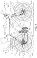
- a bicycle adopting an embodiment of the present invention is an assist bicycle in which human-powered driving is assisted by a motor-integrated hub 10.
- the bicycle includes a frame 101 having a frame body 102 and a front fork 103, a handle portion 104, a driving portion 105, a front wheel 106f, a rear wheel 106r, a front braking device 107f and a rear braking device 107r, a headlight 23, and a tail light 24.
- the front fork 103 is mounted to a front part of the frame body 102 so as to be pivotable around an inclined axis.
- the front braking device 107f and the rear braking device 107r perform braking by respectively coming into contact with rims 121f and 121r of the front wheel 106f and the rear wheel 106r.
- Respective parts including a saddle 111 and the handle portion 104 are mounted to the frame 101.
- the driving portion 105 has a crankshaft 116 rotatably supported by a hanger portion of the frame body 102, a gear crank 118a and a left crank (not shown) fixed to both ends of the crankshaft 116, a chain 119 stretched over the gear crank 118a, a gear 109 mounted to a rear hub 110 of the rear wheel 106r, a front derailleur 108f, and a rear derailleur 108r.
- the front derailleur 108f throws the chain 119 over, for example, any of three sprockets mounted to the gear crank 118a.
- the rear derailleur 108r throws the chain 119 over, for example, any of nine sprockets of the gear 109 that are mounted to the rear hub 110.
- the front derailleur 108f and the rear derailleur 108r are both electrically driven, and respectively have an electric actuator (not shown), a stage sensor that detects a present shift stage, and a derailleur control portion that controls the electric actuator and the stage sensor.
- a shift switch that instructs gear shifting is provided on the handlebar 115.
- the derailleur control portion controls the electric actuator in response to an operation of the shift switch.
- front derailleur 108f and the rear derailleur 108r are to be electrically driven in the present embodiment, the front derailleur 108f and the rear derailleur 108r may alternatively be configured so as to be coupled to shift levers via wires and shift-driven when the wires are pulled by the shift levers.
- a rear carrier 112 is mounted to a rear upper part of the frame body 102.
- a rear carrier unit 13 including an overall control portion 12 that controls electrical components 20 of the entire bicycle is mounted to the rear carrier 112.
- a power storage portion 14 that acts as a power supply for the electrical components 20 such as the motor-integrated hub 10, the overall control portion 12, and the headlight 23 (refer to Figure 3 for the electrical components 20) is detachably mounted on the rear carrier unit 13.
- the power storage portion 14 includes a storage battery.
- the storage battery includes, for example, a nickel-hydride battery or a lithium-ion battery.
- the tail light 24 is integrally mounted to the power storage portion 14.
- the handle portion 104 has a handle stem 114 fixed to an upper part of the front fork 103 and a bar handle-type handlebar 115 fixed to the handle stem 114.
- a left brake lever 16f and a right brake lever 16r are mounted on both ends of the handlebar 115.
- a display unit 18 and the headlight 23 are mounted to a central part of the handlebar 115.
- the display unit 18 is capable of displaying operating modes such as an assist mode and a regenerative brake mode.
- the motor-integrated hub 10 constitutes a hub of the front wheel 106f of the bicycle.
- the motor-integrated hub 10 is mounted to a distal end of the front fork 103 and is for assisting human power.
- the motor-integrated hub 10 includes, for example, a three-phase brushless DC motor.
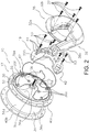
- the motor-integrated hub 10 has a hub axle 15, a motor case 17 mounted to the hub axle 15, and an electrical circuit portion 19 arranged inside the motor case 17.
- the motor-integrated hub 10 has a motor main body 10a (refer to Figure 3 ) not shown in Figure 2 .
- the motor main body 10a has a rotor rotatably supported by the hub axle 15, a stator fixed to an inner circumferential surface of a first cylindrical portion 36c, to be described later, of the motor case 17 on an outer circumferential side in a radial direction of the rotor, and a rotation transmitting mechanism that transmits rotation of the rotor to a second case member 34, to be described later, of the motor case 17.
- the rotor has a magnet (not shown) having, for example, a plurality of magnetic poles in a circumferential direction, and a magnet holding portion that holds the magnet.
- the magnet holding portion is rotatably supported by the hub axle 15 via two axle bearings arranged at an interval in a hub axle direction.
- the stator has a plurality of coils (not shown) arranged at intervals in a circumferential direction on the inner circumferential surface of the first cylindrical portion 36c. The plurality of coils are sequentially excited by an alternating current that is switched by a field-effect transistor 44 of the electrical circuit portion 19, and rotates the rotor in a direction of forward movement.
- the rotation transmitting mechanism transmits rotation of the rotor to the second case member 34 of the motor case 17 and rotates the front wheel 106f in the direction of forward movement.
- the rotation transmitting mechanism has a planetary gear mechanism (not shown).
- the planetary gear mechanism decelerates the rotation of the rotor and transmits the same to the second case member 34 of the motor case 17.
- a mechanical configuration of the motor main body is not limited to the configuration described above.
- the configuration described above includes an inner rotor-type motor, an outer rotor-type motor may be used instead.
- a configuration may be adopted in which the rotor is directly connected to the second case member 34.
- the hub axle 15 is made of, for example, steel. Both ends of the hub axle 15 are non-rotatably mountable to a front pawl portion 103a on the distal end of the front fork 103. A pair of left and right male screw portions 15b to which nut members for fixing the hub axle 15 to the front fork 103 are to be screwed is formed on outer circumferential surfaces of both ends of the hub axle 15. In addition, a fixing portion 15d having two parallel surfaces is formed on an outer circumferential surface of the male screw portion 15b. The first case member 32, to be described later, of the motor case 17 is non-rotatably coupled to the hub axle 15 at an inward position in the hub axle direction of the fixing portion 15d.
- a nut member and a locknut are screwed to one male screw portion 15b.
- a nut member (not shown) and a nut member 52 that fixes the first case member 32 are screwed to the other male screw portion 15b.
- a turning preventing washer (not shown) which respectively non-rotatably engages the fixing portion 15d and which engages a mounting groove 103b of the front fork 103 to prevent turning of the hub axle 15 is mounted to an inward position on an axial direction of the nut member.
- the motor case 17 has the first case member 32 that is non-rotatably coupled to the hub axle 15, and the second case member 34 having a first axial end rotatably supported by the first case member 32 and a second axial end rotatably supported by the hub axle 15.
- the second case member 34 is made of, for example, an aluminum alloy.
- the first case member 32 has a recessed portion 32a which is formed on an outside surface and which is capable of receiving the distal end portion of the front fork 103, and a bulging portion 32b which forms the recessed portion 32a and which bulges outward in the hub axle direction.
- a space for housing the electrical circuit portion 19 is formed inside the bulging portion 32b.
- the aforementioned motor main body 10a and various mechanisms such as the rotation transmitting mechanism are housed in a space formed by the first case member 32 and the second case member 34.
- the first case member 32 has a case main body 36 non-rotatably mounted to the hub axle 15 and a cover member 38 fixed to an outside surface of the case main body 36 by a plurality of (for example, five) mounting bolts 37.
- the electrical circuit portion 19 is housed between the cover member 38 and the case main body 36.
- the case main body 36 and the cover member 38 are made of, for example, an aluminum alloy.
- the case main body 36 has a first boss portion 36a non-rotatably coupled to the hub axle 15, a first circular plate portion 36b integrally formed with the first boss portion 36a, and a tubular first cylindrical portion 36c that extends from an outer circumferential portion of the first circular plate portion 36b toward the second case member 34.
- a noncircular coupling hole (not shown) to be non-rotatably coupled to the hub axle 15 is formed on an inner circumferential surface of the first boss portion 36a.
- An outside surface of the first circular plate portion 36b is an approximately flat surface.
- a plurality of mounting bosses 36e formed so as to protrude outward in the direction of the hub axle 15 is formed on the outside surface.
- a circuit board 42 of the electrical circuit portion 19 is fixed to the mounting bosses 36e by mounting bolts 53.
- An inner ring (not shown) of, for example, a ball bearing-type first axle bearing 30 that rotatably supports the first end of the second case member 34 is mounted to the outer circumferential surface of the first cylindrical portion 36c.
- the cover member 38 has, on an outside surface thereof, the aforementioned recessed portion 32a and the bulging portion 32b.
- a sealing member 62 that suppresses penetration of liquids into the arrangement space of the electrical circuit portion 19 is arranged between the cover member 38 and the case main body 36.
- the sealing member 62 is formed by rubber or the like which is waterproof and elastic. As shown in Figure 2 , the sealing member 62 is mounted to a sealing groove 36f formed on the outside surface of the first circular plate portion 36b of the case main body 36.
- the recessed portion 32a is formed slightly wider than a distal end shape of an ordinary front fork so as to be able to receive front forks of various shapes.
- the electrical circuit portion 19 fixed to the first circular plate portion 36b is arranged inside the bulging portion 32b.
- a radiator sheet (not shown) for collectively cooling a plurality of semiconductor elements (in particular, the field-effect transistor 44 to be described later) is mounted on an inside surface of the bulging portion 32b.
- a wiring connecting portion 38a is formed on one edge of the recessed portion 32a so as to protrude outward in a circumferential direction of the case main body 36.
- the wiring connecting portion 38a is formed slightly depressed in the hub axle direction than the bulging portion 32b.
- the wiring connecting portion 38a is provided in order to extract, to the outside, a duplex electric power line that connects the electrical circuit portion 19 with the overall control portion 12 and the power storage portion 14.
- the wiring connecting portion 38a is formed in proximity to a rear portion of the front fork 103 and is arranged along the front fork 103.
- an electric power line 70 (refer to Figure 3 ) is configured so as to be capable of performing power supply and signal communication due to PLC (power line communications).
- the second case member 34 has a structure similar to a hub shell of an ordinary bicycle hub and is a bottomed tubular member.
- the second case member 34 is rotatably mounted to the hub axle 15.
- the second case member 34 has a second boss portion (not shown) rotatably coupled to the hub axle 15 via an axle bearing, a second circular plate portion (not shown) integrally formed with the second boss portion, and a second cylindrical portion 34d tubularly extending inward in the hub axle direction from an outer circumferential portion of the second circular plate portion.
- the second cylindrical portion 34d is arranged on an outer circumferential side of the first cylindrical portion 36c.
- An outer ring (not shown) of the first axle bearing 30 is mounted to a first end-side inner circumferential surface of the second cylindrical portion 34d.
- a first hub flange 40a and a second hub flange 40b for coupling the rim 121f of the front wheel 106f and the motor-integrated hub 10 with each other by spokes 122 are formed at an interval at both ends in the hub axle direction on an outer circumferential surface of the second cylindrical portion 34d.
- the electrical circuit portion 19 controls driving of the motor-integrated hub 10 and supplementarily controls power supplied to the electrical components 20.
- the electrical circuit portion 19 has a function of a DC-AC inverter which switches a direct current supplied from the power storage portion 14 and converts the direct current into an alternating current.
- the electrical circuit portion 19 has a function of a rotation sensor that detects at least any of a rotation and a rotational speed of the motor-integrated hub 10 from a frequency of the switching.
- the electrical circuit portion 19 also has a regenerative driving function for varying a ratio of regenerative braking, in which braking is performed by using the motor-integrated hub 10 as a power generator, by controlling the overall control portion 12 during such regeneratively braking.
- the electrical circuit portion 19 also has a dynamo function in which the motor main body 10a (power generating portion) arranged inside the motor-integrated hub 10 is used as a power generator to supply power at which the electrical components 20 are operable to the electrical components 20.
- the electrical circuit portion 19 has an electric power line communication portion (not shown) for performing electric power line communication.
- the electric power line communication portion communicates with the overall control portion 12 that is an electrical component 20 via the electric power line 70 and delivers a command from the overall control portion 12 to the electrical circuit portion 19.
- the electrical circuit portion 19 has a motor drive circuit 41 and an auxiliary power supply circuit 200.
- the motor drive circuit 41 has a plurality of (for example, six) field-effect transistors (FETs) 44 mounted to the circuit board 42 fixed to the outside surface of the case main body 36, and other electronic parts including a motor control element 46.
- FETs field-effect transistors
- a voltage from the electric power line 70 is inputted to the motor drive circuit 41.
- the plurality of field-effect transistors 44 are arranged in contact with the radiator sheet. As such, heat mainly generated at the field-effect transistors 44 can be discharged to the outside via the cover member 38.
- the auxiliary power supply circuit 200 supplementarily controls power to be supplied to the electrical components 20.
- the auxiliary power supply circuit 200 is mounted to the circuit board 42.
- the auxiliary power supply circuit 200 is mounted to a rear surface (indicated by a dashed line in Figure 2 ) of the circuit board 42 shown in Figure 2 . Details of the auxiliary power supply circuit 200 will be described with reference to the auxiliary power supply system 100 to be described later.
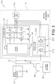
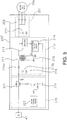
- the auxiliary power supply system 100 supplies power to electrical components 20 mountable to the bicycle depending on a supply situation of power from a power supply mounted on the bicycle.
- the auxiliary power supply system 100 has the motor main body 10a arranged inside the motor-integrated hub 10, the auxiliary power supply circuit 200 (auxiliary power supply portion) for supplying power to the electrical components 20 when the supply of power from the power supply is suspended, and a first diode 47.
- Output of the power storage portion 14 that supplies power necessary for driving the motor main body 10a varies according to power storage states. For example, when fully charged, the power storage portion 14 outputs a maximum voltage. As the amount of charge of the power storage portion 14 decreases, the output voltage decreases from the maximum voltage to a minimum voltage. For example, as the amount of charge of the power storage portion 14 decreases, the output voltage decreases from 24 V (maximum voltage) to 18 V (minimum voltage). Subsequently, when power stored in the power storage portion 14 runs out or the power storage amount drops to or below a predetermined amount, output from the power storage portion 14 is suspended.
- the motor main body 10a is coupled to the motor drive circuit 41 via wiring such as three power lines for driving and controlling the motor main body 10a.
- wiring such as three power lines for driving and controlling the motor main body 10a.
- each of the three power lines that couple the motor main body 10a and the motor drive circuit 41 to each other is coupled to the auxiliary power supply circuit 200.
- the auxiliary power supply circuit 200 is operated by power from the motor main body 10a provided in the bicycle.
- the auxiliary power supply circuit 200 supplies power generated by the motor main body 10a to the electrical components 20 depending on a power output state of the power storage portion 14 mounted on the bicycle. More specifically, the auxiliary power supply circuit 200 converts power generated by the motor main body 10a into a voltage or a current at which the electrical components 20 are operable and outputs the voltage or current.
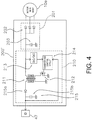
- the auxiliary power supply circuit 200 has a first rectifier circuit 201 (rectifying portion) that rectifies a voltage from the motor main body 10a and a buck-boost circuit 210 (voltage converting portion) that transforms the rectified voltage.
- a first rectifier circuit 201 rectififying portion
- a buck-boost circuit 210 voltage converting portion
- the first rectifier circuit 201 is a circuit that rectifies and smoothes a voltage from the motor main body 10a.
- the first rectifier circuit 201 rectifies and smoothes an alternating-current voltage from the motor main body 10a.
- the first rectifier circuit 201 has a second diode 202 and a capacitor 203.
- the second diode 202 is connected to each power line and applies half-wave rectification to an alternating-current voltage inputted from each power line.
- the voltage subjected to half-wave rectification is inputted to the capacitor 203 to be smoothed by the capacitor 203.
- the buck-boost circuit 210 is a circuit for adjusting a direct-current voltage rectified by the first rectifier circuit 201 into a predetermined voltage (first voltage).
- the buck-boost circuit 210 is operated using a direct-current voltage rectified by the first rectifier circuit 201.
- the buck-boost circuit 210 has a transformer circuit 211, a first switch circuit 212, a transforming DC-DC converter 213, a transforming control circuit 214, and a second rectifier circuit 215.
- the transformer circuit 211 adjusts a direct-current voltage rectified by the first rectifier circuit 201 into a predetermined voltage.
- the predetermined voltage is set equal to or higher than a voltage at which the electrical components 20 are operable (second voltage) and lower than a minimum voltage outputtable from the power storage portion 14.
- a voltage at which the electrical components 20 are operable is 6 V and a minimum voltage outputtable from the power storage portion 14 is 18 V.
- the example shows the predetermined voltage set to 10 V.
- the first switch circuit 212 is connected to the transformer circuit 211. Due to an on/off operation of the first switch circuit 212, the transformer circuit 211 adjusts a direct-current voltage rectified by the first rectifier circuit 201 into 10 V.
- the first switch circuit 212 is arranged between the transformer circuit 211 and the transforming control circuit 214.
- the first switch circuit 212 is, for example, an FET (field effect transistor).
- the FET operates as a switch.
- An on/off state of the first switch circuit 212 is controlled by the transforming control circuit 214.
- a ratio of input voltage to on/off time is controlled by the transforming control circuit 214 so as to adjust the output voltage to 10 V.
- the second rectifier circuit 215 rectifies and smoothes a voltage outputted from the transformer circuit 211.
- the second rectifier circuit 215 has a third diode 215a and a capacitor 215b.
- the third diode 215a rectifies a voltage adjusted by the transformer circuit 211.
- this voltage is applied to the capacitor 215b to be smoothed by the capacitor 215b.
- the transforming DC-DC converter 213 adjusts a voltage rectified by the first rectifier circuit 201 into a voltage at which the transforming control circuit 214 is operable.
- the voltage rectified by the first rectifier circuit 201 is adjusted to a predetermined voltage such as 6 V.
- the transforming control circuit 214 is activated and operated by a voltage adjusted by the transforming DC-DC converter 213.
- the transforming control circuit 214 monitors a voltage rectified by the second rectifier circuit 215.
- the transforming control circuit 214 controls the first switch circuit 212 so that the voltage rectified by the second rectifier circuit 215 assumes a predetermined voltage such as 10 V. Accordingly, a voltage outputted from the buck-boost circuit 210 can be constantly adjusted to a predetermined voltage such as 10 V.
- the transforming control circuit 214 is activated and operated by power supplied from the transforming DC-DC converter 213. Therefore, even if supply of power from the power storage portion 14 is suspended, as long as the motor main body 10a is rotating, the transforming control circuit 214 can be activated and operated by power outputted from the motor main body 10a.
- Direct-current power adjusted by the buck-boost circuit 210 is supplied to the electrical components 20 via the first diode 47.
- An anode of the first diode 47 is electrically connected to the auxiliary power supply circuit 200 and a cathode of the first diode 47 is electrically connected to the electrical components 20. More specifically, the anode of the first diode 47 is electrically connected to the auxiliary power supply circuit 200 and the cathode of the first diode 47 is electrically connected to the electrical components 20 via an electrical component DC-DC converter 48.
- the first diode 47 prevents a voltage from the power storage portion 14 from being applied to the auxiliary power supply circuit 200 that is also electrically connected to the power storage portion 14.
- a current from the power storage portion 14 can be regulated so as not to counterflow into the auxiliary power supply circuit even if the voltage outputted from the power storage portion 14 exceeds the first voltage such as 10 V (refer to Figure 3 ).
- the voltage adjusted to the first voltage at the buck-boost circuit 210 is applied to the electrical components 20 and power is supplied.
- the electrical component DC-DC converter 48 is arranged between the diode and the electrical components 20.
- the electrical component DC-DC converter 48 adjusts a voltage outputted from the auxiliary power supply circuit 200 such as a voltage of 10 V (first voltage) to a voltage at which the electrical components 20 are operable such as a voltage of 6 V (second voltage).
- a voltage of 10 V first voltage
- 6 V second voltage
- the voltage of 6 V adjusted at this point is inputted to the electrical components 20 to activate and operate the electrical components 20.
- power can be stably supplied to the electrical components 20 of a bicycle depending on a supply situation of power from the power storage portion 14.
- the motor main body 10a arranged inside the motor-integrated hub 10 as a power generator, power outputted from the motor main body 10a can be adjusted by the auxiliary power supply system 100 to a voltage optimal for the electrical components 20. Accordingly, power can be stably supplied to the electrical components 20 without having to rely on the rotation of the motor main body 10a.
- power can be stably supplied to the electrical components of the bicycle using only existing equipment and without having to particularly provide other power supplying means.
Landscapes
- Engineering & Computer Science (AREA)
- Power Engineering (AREA)
- Transportation (AREA)
- Mechanical Engineering (AREA)
- Life Sciences & Earth Sciences (AREA)
- Sustainable Development (AREA)
- Sustainable Energy (AREA)
- Chemical & Material Sciences (AREA)
- Combustion & Propulsion (AREA)
- Electric Propulsion And Braking For Vehicles (AREA)
- Charge And Discharge Circuits For Batteries Or The Like (AREA)
Applications Claiming Priority (1)
| Application Number | Priority Date | Filing Date | Title |
|---|---|---|---|
| JP2010133828A JP5300792B2 (ja) | 2010-06-11 | 2010-06-11 | 自転車用の補助電源システム |
Publications (3)
| Publication Number | Publication Date |
|---|---|
| EP2394841A2 EP2394841A2 (en) | 2011-12-14 |
| EP2394841A3 EP2394841A3 (en) | 2013-07-03 |
| EP2394841B1 true EP2394841B1 (en) | 2018-08-08 |
Family
ID=44691093
Family Applications (1)
| Application Number | Title | Priority Date | Filing Date |
|---|---|---|---|
| EP11168331.4A Active EP2394841B1 (en) | 2010-06-11 | 2011-06-01 | Bicycle auxiliary power supply system |
Country Status (5)
| Country | Link |
|---|---|
| US (1) | US8981588B2 (ja) |
| EP (1) | EP2394841B1 (ja) |
| JP (1) | JP5300792B2 (ja) |
| CN (1) | CN102294958B (ja) |
| TW (1) | TWI499526B (ja) |
Families Citing this family (19)
| Publication number | Priority date | Publication date | Assignee | Title |
|---|---|---|---|---|
| JP5149938B2 (ja) * | 2010-06-11 | 2013-02-20 | 株式会社シマノ | モータ内蔵自転車用ハブ |
| JP5373946B1 (ja) * | 2012-08-17 | 2013-12-18 | 株式会社シマノ | 自転車用駆動ユニット |
| US9428246B2 (en) * | 2011-12-09 | 2016-08-30 | Shimano Inc. | Bicycle generator and/or shifting device |
| US9561734B2 (en) | 2012-07-31 | 2017-02-07 | Shimano Inc. | Bicycle power supply system |
| JP5668036B2 (ja) | 2012-09-24 | 2015-02-12 | 太陽誘電株式会社 | モータ駆動制御装置及び電動アシスト車 |
| JP5670403B2 (ja) * | 2012-10-29 | 2015-02-18 | 太陽誘電株式会社 | モータ駆動制御装置及び電動アシスト車 |
| TWI535622B (zh) | 2013-01-25 | 2016-06-01 | li-he Yao | Bicycle electric device |
| US9914501B2 (en) * | 2014-03-18 | 2018-03-13 | Askoll Eva S.R.L. | Battery holder device for electric bicycle |
| US9533736B2 (en) * | 2014-10-09 | 2017-01-03 | Shimano Inc. | Bicycle drive unit |
| JP6495783B2 (ja) * | 2015-08-25 | 2019-04-03 | 太陽誘電株式会社 | 制御装置、蓄電装置及び移動体 |
| JP7073063B2 (ja) * | 2016-09-30 | 2022-05-23 | 太陽誘電株式会社 | モータ駆動制御装置及び電動アシスト車 |
| EP3308993A1 (en) | 2016-09-30 | 2018-04-18 | Taiyo Yuden Co., Ltd. | Motor driving control apparatus and electrically assisted vehicle |
| JP6789095B2 (ja) * | 2016-12-21 | 2020-11-25 | 株式会社シマノ | 自転車用内装変速ハブ |
| US10773769B2 (en) * | 2017-04-03 | 2020-09-15 | Shimano Inc. | Bicycle drive system, bicycle drive unit, and bicycle battery unit |
| JP6849565B2 (ja) * | 2017-04-03 | 2021-03-24 | 株式会社シマノ | 自転車用駆動システム、自転車用ドライブユニット、および、自転車用バッテリユニット |
| CN109178187B (zh) * | 2018-07-30 | 2020-06-16 | 苏州小蜻蜓电动车有限公司 | 一种节省空间的电动自行车供电系统及安装方法 |
| JP7186069B2 (ja) * | 2018-11-19 | 2022-12-08 | 株式会社シマノ | ブレーキシステム |
| CN109599927A (zh) * | 2018-12-07 | 2019-04-09 | 广州市昌菱电气有限公司 | 自行车电动助力驱动控制系统及自行车 |
| EP3986780A4 (en) * | 2019-06-21 | 2023-07-12 | Other Lab, LLC | SOLAR POWERED ELECTRIC VEHICLE SYSTEM AND METHOD |
Family Cites Families (18)
| Publication number | Priority date | Publication date | Assignee | Title |
|---|---|---|---|---|
| JPH0323963A (ja) * | 1989-06-21 | 1991-01-31 | Canon Inc | 印字装置 |
| AU692818B2 (en) * | 1994-01-11 | 1998-06-18 | Edwin Schwaller | Bicycle lighting system and generator |
| JPH09123963A (ja) * | 1995-10-27 | 1997-05-13 | Riken Corp | 自転車用灯火装置 |
| JP2003335290A (ja) * | 2002-05-21 | 2003-11-25 | Matsushita Electric Ind Co Ltd | 補助動力装置付き自転車 |
| JP2004149001A (ja) * | 2002-10-30 | 2004-05-27 | Sanyo Electric Co Ltd | 電動自転車 |
| JP4549124B2 (ja) | 2004-03-18 | 2010-09-22 | 三洋電機株式会社 | モータ制御装置 |
| FR2870794B1 (fr) * | 2004-06-01 | 2008-06-13 | Jjg Partenaire Eurl Entpr Unip | Vehicule a assistance electrique et circuit electrique d'alimentation pour un tel vehicule |
| EP1795438A1 (en) * | 2004-08-09 | 2007-06-13 | Nikko Co., Ltd. | Wheel mounted with device doubling as both in-hub dc generator for bicycle and motor for auxiliary power |
| US20090266636A1 (en) * | 2004-08-20 | 2009-10-29 | Hans Peter Naegeli | Hybrid motorbike powered by muscle power and an electric motor with the current generated by a fuel cell |
| JP2006260809A (ja) * | 2005-03-15 | 2006-09-28 | Sanyo Tekunika:Kk | 照明器具の駆動装置 |
| JP4816128B2 (ja) * | 2006-02-21 | 2011-11-16 | 株式会社デンソー | 車両用発電制御装置 |
| JP2008044414A (ja) * | 2006-08-11 | 2008-02-28 | Sanyo Electric Co Ltd | 電動補助自転車 |
| JP4326553B2 (ja) * | 2006-10-30 | 2009-09-09 | 株式会社シマノ | 自転車用発電装置 |
| CN101531142A (zh) * | 2008-03-11 | 2009-09-16 | 南京金城电动车业有限公司 | 电动自行车再生充电装置 |
| JP2009220669A (ja) * | 2008-03-14 | 2009-10-01 | Sanyo Electric Co Ltd | 電動自転車 |
| JP5268479B2 (ja) * | 2008-07-31 | 2013-08-21 | パナソニック株式会社 | 電動補助自転車 |
| CN101741125A (zh) * | 2008-11-17 | 2010-06-16 | 陈炯 | 一种电动自行车自充电方法和自充电电动自行车 |
| JP2010133828A (ja) | 2008-12-04 | 2010-06-17 | Denso Corp | レーダ装置 |
-
2010
- 2010-06-11 JP JP2010133828A patent/JP5300792B2/ja active Active
-
2011
- 2011-06-01 EP EP11168331.4A patent/EP2394841B1/en active Active
- 2011-06-07 TW TW100119820A patent/TWI499526B/zh active
- 2011-06-10 US US13/157,385 patent/US8981588B2/en active Active
- 2011-06-10 CN CN201110155115.4A patent/CN102294958B/zh active Active
Non-Patent Citations (1)
| Title |
|---|
| None * |
Also Published As
| Publication number | Publication date |
|---|---|
| JP5300792B2 (ja) | 2013-09-25 |
| CN102294958A (zh) | 2011-12-28 |
| EP2394841A2 (en) | 2011-12-14 |
| TWI499526B (zh) | 2015-09-11 |
| US20110304200A1 (en) | 2011-12-15 |
| US8981588B2 (en) | 2015-03-17 |
| EP2394841A3 (en) | 2013-07-03 |
| CN102294958B (zh) | 2014-05-14 |
| JP2011255841A (ja) | 2011-12-22 |
| TW201221385A (en) | 2012-06-01 |
Similar Documents
| Publication | Publication Date | Title |
|---|---|---|
| EP2394841B1 (en) | Bicycle auxiliary power supply system | |
| EP2394903B1 (en) | Motor-integrated bicycle hub | |
| US10967934B2 (en) | Electric drive wheel hub system for a vehicle and a vehicle incorporating the same | |
| JP3396655B2 (ja) | 自転車用電源装置 | |
| KR100471093B1 (ko) | 전원장치 | |
| US8893833B2 (en) | Swing arm device for electric two- or three-wheeled vehicle | |
| EP2394902A1 (en) | Bicycle motor control system | |
| KR20140052937A (ko) | 전기 차량용 전자기계 컨버터 시스템 | |
| US10807477B2 (en) | Charging device and method for charging an electrical energy storage device of a vehicle, as well as motor vehicle | |
| US7187088B2 (en) | Power supply apparatus for electric vehicle | |
| KR20160128942A (ko) | 이중 배터리 패키지 및 이의 작동방법 | |
| CA3002325A1 (en) | An energy harvesting power-assist system and method for light vehicles | |
| WO2011013583A1 (ja) | モータ駆動装置及びこれを備えた電動アシスト車 | |
| WO2022249981A1 (ja) | 電動アシスト自転車 | |
| EP2080662B1 (en) | Fuel cell vehicle and DC/DC converter apparatus | |
| KR20160128805A (ko) | 이중 배터리 패키지 | |
| RU2556051C1 (ru) | Транспортное средство с комбинированным мускульным и электрическим приводом | |
| WO2023094959A1 (en) | An universal on-board charger cum inverter system | |
| CN116691910A (zh) | 人力车用柔性直流传动系统及方法 | |
| JP2005086921A (ja) | 電源装置およびそれを搭載した自動車 |
Legal Events
| Date | Code | Title | Description |
|---|---|---|---|
| AK | Designated contracting states |
Kind code of ref document: A2 Designated state(s): AL AT BE BG CH CY CZ DE DK EE ES FI FR GB GR HR HU IE IS IT LI LT LU LV MC MK MT NL NO PL PT RO RS SE SI SK SM TR |
|
| AX | Request for extension of the european patent |
Extension state: BA ME |
|
| PUAI | Public reference made under article 153(3) epc to a published international application that has entered the european phase |
Free format text: ORIGINAL CODE: 0009012 |
|
| PUAL | Search report despatched |
Free format text: ORIGINAL CODE: 0009013 |
|
| AK | Designated contracting states |
Kind code of ref document: A3 Designated state(s): AL AT BE BG CH CY CZ DE DK EE ES FI FR GB GR HR HU IE IS IT LI LT LU LV MC MK MT NL NO PL PT RO RS SE SI SK SM TR |
|
| AX | Request for extension of the european patent |
Extension state: BA ME |
|
| RIC1 | Information provided on ipc code assigned before grant |
Ipc: B62M 25/08 20060101ALI20130527BHEP Ipc: B60L 11/18 20060101AFI20130527BHEP Ipc: B62M 6/40 20100101ALI20130527BHEP Ipc: B60L 7/14 20060101ALI20130527BHEP |
|
| 17P | Request for examination filed |
Effective date: 20140103 |
|
| RBV | Designated contracting states (corrected) |
Designated state(s): AL AT BE BG CH CY CZ DE DK EE ES FI FR GB GR HR HU IE IS IT LI LT LU LV MC MK MT NL NO PL PT RO RS SE SI SK SM TR |
|
| 17Q | First examination report despatched |
Effective date: 20160323 |
|
| STAA | Information on the status of an ep patent application or granted ep patent |
Free format text: STATUS: EXAMINATION IS IN PROGRESS |
|
| REG | Reference to a national code |
Ref country code: DE Ref legal event code: R079 Ref document number: 602011050744 Country of ref document: DE Free format text: PREVIOUS MAIN CLASS: B60L0011180000 Ipc: B60L0001140000 |
|
| RIC1 | Information provided on ipc code assigned before grant |
Ipc: B60L 11/18 20060101ALI20180111BHEP Ipc: B60L 11/00 20060101ALI20180111BHEP Ipc: B60L 7/16 20060101ALI20180111BHEP Ipc: B60L 1/14 20060101AFI20180111BHEP Ipc: B62M 25/08 20060101ALI20180111BHEP |
|
| GRAP | Despatch of communication of intention to grant a patent |
Free format text: ORIGINAL CODE: EPIDOSNIGR1 |
|
| STAA | Information on the status of an ep patent application or granted ep patent |
Free format text: STATUS: GRANT OF PATENT IS INTENDED |
|
| INTG | Intention to grant announced |
Effective date: 20180216 |
|
| GRAS | Grant fee paid |
Free format text: ORIGINAL CODE: EPIDOSNIGR3 |
|
| GRAA | (expected) grant |
Free format text: ORIGINAL CODE: 0009210 |
|
| STAA | Information on the status of an ep patent application or granted ep patent |
Free format text: STATUS: THE PATENT HAS BEEN GRANTED |
|
| RAP1 | Party data changed (applicant data changed or rights of an application transferred) |
Owner name: SHIMANO, INC. Owner name: TAIYO YUDEN CO., LTD. |
|
| AK | Designated contracting states |
Kind code of ref document: B1 Designated state(s): AL AT BE BG CH CY CZ DE DK EE ES FI FR GB GR HR HU IE IS IT LI LT LU LV MC MK MT NL NO PL PT RO RS SE SI SK SM TR |
|
| REG | Reference to a national code |
Ref country code: GB Ref legal event code: FG4D |
|
| REG | Reference to a national code |
Ref country code: CH Ref legal event code: EP Ref country code: AT Ref legal event code: REF Ref document number: 1026595 Country of ref document: AT Kind code of ref document: T Effective date: 20180815 |
|
| REG | Reference to a national code |
Ref country code: IE Ref legal event code: FG4D |
|
| REG | Reference to a national code |
Ref country code: DE Ref legal event code: R096 Ref document number: 602011050744 Country of ref document: DE |
|
| REG | Reference to a national code |
Ref country code: NL Ref legal event code: MP Effective date: 20180808 |
|
| REG | Reference to a national code |
Ref country code: LT Ref legal event code: MG4D |
|
| REG | Reference to a national code |
Ref country code: AT Ref legal event code: MK05 Ref document number: 1026595 Country of ref document: AT Kind code of ref document: T Effective date: 20180808 |
|
| PG25 | Lapsed in a contracting state [announced via postgrant information from national office to epo] |
Ref country code: LT Free format text: LAPSE BECAUSE OF FAILURE TO SUBMIT A TRANSLATION OF THE DESCRIPTION OR TO PAY THE FEE WITHIN THE PRESCRIBED TIME-LIMIT Effective date: 20180808 Ref country code: PL Free format text: LAPSE BECAUSE OF FAILURE TO SUBMIT A TRANSLATION OF THE DESCRIPTION OR TO PAY THE FEE WITHIN THE PRESCRIBED TIME-LIMIT Effective date: 20180808 Ref country code: SE Free format text: LAPSE BECAUSE OF FAILURE TO SUBMIT A TRANSLATION OF THE DESCRIPTION OR TO PAY THE FEE WITHIN THE PRESCRIBED TIME-LIMIT Effective date: 20180808 Ref country code: NL Free format text: LAPSE BECAUSE OF FAILURE TO SUBMIT A TRANSLATION OF THE DESCRIPTION OR TO PAY THE FEE WITHIN THE PRESCRIBED TIME-LIMIT Effective date: 20180808 Ref country code: AT Free format text: LAPSE BECAUSE OF FAILURE TO SUBMIT A TRANSLATION OF THE DESCRIPTION OR TO PAY THE FEE WITHIN THE PRESCRIBED TIME-LIMIT Effective date: 20180808 Ref country code: BG Free format text: LAPSE BECAUSE OF FAILURE TO SUBMIT A TRANSLATION OF THE DESCRIPTION OR TO PAY THE FEE WITHIN THE PRESCRIBED TIME-LIMIT Effective date: 20181108 Ref country code: FI Free format text: LAPSE BECAUSE OF FAILURE TO SUBMIT A TRANSLATION OF THE DESCRIPTION OR TO PAY THE FEE WITHIN THE PRESCRIBED TIME-LIMIT Effective date: 20180808 Ref country code: RS Free format text: LAPSE BECAUSE OF FAILURE TO SUBMIT A TRANSLATION OF THE DESCRIPTION OR TO PAY THE FEE WITHIN THE PRESCRIBED TIME-LIMIT Effective date: 20180808 Ref country code: IS Free format text: LAPSE BECAUSE OF FAILURE TO SUBMIT A TRANSLATION OF THE DESCRIPTION OR TO PAY THE FEE WITHIN THE PRESCRIBED TIME-LIMIT Effective date: 20181208 Ref country code: GR Free format text: LAPSE BECAUSE OF FAILURE TO SUBMIT A TRANSLATION OF THE DESCRIPTION OR TO PAY THE FEE WITHIN THE PRESCRIBED TIME-LIMIT Effective date: 20181109 Ref country code: NO Free format text: LAPSE BECAUSE OF FAILURE TO SUBMIT A TRANSLATION OF THE DESCRIPTION OR TO PAY THE FEE WITHIN THE PRESCRIBED TIME-LIMIT Effective date: 20181108 |
|
| PG25 | Lapsed in a contracting state [announced via postgrant information from national office to epo] |
Ref country code: ES Free format text: LAPSE BECAUSE OF FAILURE TO SUBMIT A TRANSLATION OF THE DESCRIPTION OR TO PAY THE FEE WITHIN THE PRESCRIBED TIME-LIMIT Effective date: 20180808 Ref country code: LV Free format text: LAPSE BECAUSE OF FAILURE TO SUBMIT A TRANSLATION OF THE DESCRIPTION OR TO PAY THE FEE WITHIN THE PRESCRIBED TIME-LIMIT Effective date: 20180808 Ref country code: HR Free format text: LAPSE BECAUSE OF FAILURE TO SUBMIT A TRANSLATION OF THE DESCRIPTION OR TO PAY THE FEE WITHIN THE PRESCRIBED TIME-LIMIT Effective date: 20180808 Ref country code: AL Free format text: LAPSE BECAUSE OF FAILURE TO SUBMIT A TRANSLATION OF THE DESCRIPTION OR TO PAY THE FEE WITHIN THE PRESCRIBED TIME-LIMIT Effective date: 20180808 |
|
| PG25 | Lapsed in a contracting state [announced via postgrant information from national office to epo] |
Ref country code: IT Free format text: LAPSE BECAUSE OF FAILURE TO SUBMIT A TRANSLATION OF THE DESCRIPTION OR TO PAY THE FEE WITHIN THE PRESCRIBED TIME-LIMIT Effective date: 20180808 Ref country code: EE Free format text: LAPSE BECAUSE OF FAILURE TO SUBMIT A TRANSLATION OF THE DESCRIPTION OR TO PAY THE FEE WITHIN THE PRESCRIBED TIME-LIMIT Effective date: 20180808 Ref country code: RO Free format text: LAPSE BECAUSE OF FAILURE TO SUBMIT A TRANSLATION OF THE DESCRIPTION OR TO PAY THE FEE WITHIN THE PRESCRIBED TIME-LIMIT Effective date: 20180808 Ref country code: CZ Free format text: LAPSE BECAUSE OF FAILURE TO SUBMIT A TRANSLATION OF THE DESCRIPTION OR TO PAY THE FEE WITHIN THE PRESCRIBED TIME-LIMIT Effective date: 20180808 |
|
| REG | Reference to a national code |
Ref country code: DE Ref legal event code: R097 Ref document number: 602011050744 Country of ref document: DE |
|
| PG25 | Lapsed in a contracting state [announced via postgrant information from national office to epo] |
Ref country code: DK Free format text: LAPSE BECAUSE OF FAILURE TO SUBMIT A TRANSLATION OF THE DESCRIPTION OR TO PAY THE FEE WITHIN THE PRESCRIBED TIME-LIMIT Effective date: 20180808 Ref country code: SK Free format text: LAPSE BECAUSE OF FAILURE TO SUBMIT A TRANSLATION OF THE DESCRIPTION OR TO PAY THE FEE WITHIN THE PRESCRIBED TIME-LIMIT Effective date: 20180808 Ref country code: SM Free format text: LAPSE BECAUSE OF FAILURE TO SUBMIT A TRANSLATION OF THE DESCRIPTION OR TO PAY THE FEE WITHIN THE PRESCRIBED TIME-LIMIT Effective date: 20180808 |
|
| PLBE | No opposition filed within time limit |
Free format text: ORIGINAL CODE: 0009261 |
|
| STAA | Information on the status of an ep patent application or granted ep patent |
Free format text: STATUS: NO OPPOSITION FILED WITHIN TIME LIMIT |
|
| 26N | No opposition filed |
Effective date: 20190509 |
|
| PG25 | Lapsed in a contracting state [announced via postgrant information from national office to epo] |
Ref country code: SI Free format text: LAPSE BECAUSE OF FAILURE TO SUBMIT A TRANSLATION OF THE DESCRIPTION OR TO PAY THE FEE WITHIN THE PRESCRIBED TIME-LIMIT Effective date: 20180808 |
|
| PG25 | Lapsed in a contracting state [announced via postgrant information from national office to epo] |
Ref country code: MC Free format text: LAPSE BECAUSE OF FAILURE TO SUBMIT A TRANSLATION OF THE DESCRIPTION OR TO PAY THE FEE WITHIN THE PRESCRIBED TIME-LIMIT Effective date: 20180808 |
|
| REG | Reference to a national code |
Ref country code: CH Ref legal event code: PL |
|
| GBPC | Gb: european patent ceased through non-payment of renewal fee |
Effective date: 20190601 |
|
| REG | Reference to a national code |
Ref country code: BE Ref legal event code: MM Effective date: 20190630 |
|
| PG25 | Lapsed in a contracting state [announced via postgrant information from national office to epo] |
Ref country code: TR Free format text: LAPSE BECAUSE OF FAILURE TO SUBMIT A TRANSLATION OF THE DESCRIPTION OR TO PAY THE FEE WITHIN THE PRESCRIBED TIME-LIMIT Effective date: 20180808 |
|
| PG25 | Lapsed in a contracting state [announced via postgrant information from national office to epo] |
Ref country code: IE Free format text: LAPSE BECAUSE OF NON-PAYMENT OF DUE FEES Effective date: 20190601 Ref country code: GB Free format text: LAPSE BECAUSE OF NON-PAYMENT OF DUE FEES Effective date: 20190601 |
|
| PG25 | Lapsed in a contracting state [announced via postgrant information from national office to epo] |
Ref country code: LU Free format text: LAPSE BECAUSE OF NON-PAYMENT OF DUE FEES Effective date: 20190601 Ref country code: BE Free format text: LAPSE BECAUSE OF NON-PAYMENT OF DUE FEES Effective date: 20190630 Ref country code: LI Free format text: LAPSE BECAUSE OF NON-PAYMENT OF DUE FEES Effective date: 20190630 Ref country code: CH Free format text: LAPSE BECAUSE OF NON-PAYMENT OF DUE FEES Effective date: 20190630 |
|
| PG25 | Lapsed in a contracting state [announced via postgrant information from national office to epo] |
Ref country code: PT Free format text: LAPSE BECAUSE OF FAILURE TO SUBMIT A TRANSLATION OF THE DESCRIPTION OR TO PAY THE FEE WITHIN THE PRESCRIBED TIME-LIMIT Effective date: 20181208 Ref country code: FR Free format text: LAPSE BECAUSE OF NON-PAYMENT OF DUE FEES Effective date: 20190630 |
|
| REG | Reference to a national code |
Ref country code: DE Ref legal event code: R082 Ref document number: 602011050744 Country of ref document: DE Representative=s name: SONNENBERG HARRISON PARTNERSCHAFT MBB, DE Ref country code: DE Ref legal event code: R082 Ref document number: 602011050744 Country of ref document: DE Representative=s name: SONNENBERG HARRISON PARTNERSCHAFT MBB PATENT- , DE |
|
| PG25 | Lapsed in a contracting state [announced via postgrant information from national office to epo] |
Ref country code: CY Free format text: LAPSE BECAUSE OF FAILURE TO SUBMIT A TRANSLATION OF THE DESCRIPTION OR TO PAY THE FEE WITHIN THE PRESCRIBED TIME-LIMIT Effective date: 20180808 |
|
| PG25 | Lapsed in a contracting state [announced via postgrant information from national office to epo] |
Ref country code: HU Free format text: LAPSE BECAUSE OF FAILURE TO SUBMIT A TRANSLATION OF THE DESCRIPTION OR TO PAY THE FEE WITHIN THE PRESCRIBED TIME-LIMIT; INVALID AB INITIO Effective date: 20110601 Ref country code: MT Free format text: LAPSE BECAUSE OF FAILURE TO SUBMIT A TRANSLATION OF THE DESCRIPTION OR TO PAY THE FEE WITHIN THE PRESCRIBED TIME-LIMIT Effective date: 20180808 |
|
| PG25 | Lapsed in a contracting state [announced via postgrant information from national office to epo] |
Ref country code: MK Free format text: LAPSE BECAUSE OF FAILURE TO SUBMIT A TRANSLATION OF THE DESCRIPTION OR TO PAY THE FEE WITHIN THE PRESCRIBED TIME-LIMIT Effective date: 20180808 |
|
| P01 | Opt-out of the competence of the unified patent court (upc) registered |
Effective date: 20230519 |
|
| PGFP | Annual fee paid to national office [announced via postgrant information from national office to epo] |
Ref country code: DE Payment date: 20220914 Year of fee payment: 13 |