EP2392532A2 - Wickler - Google Patents
Wickler Download PDFInfo
- Publication number
- EP2392532A2 EP2392532A2 EP11166875A EP11166875A EP2392532A2 EP 2392532 A2 EP2392532 A2 EP 2392532A2 EP 11166875 A EP11166875 A EP 11166875A EP 11166875 A EP11166875 A EP 11166875A EP 2392532 A2 EP2392532 A2 EP 2392532A2
- Authority
- EP
- European Patent Office
- Prior art keywords
- contact roller
- yarns
- bobbin
- turret table
- tilt mechanism
- Prior art date
- Legal status (The legal status is an assumption and is not a legal conclusion. Google has not performed a legal analysis and makes no representation as to the accuracy of the status listed.)
- Granted
Links
Images


Classifications
-
- B—PERFORMING OPERATIONS; TRANSPORTING
- B65—CONVEYING; PACKING; STORING; HANDLING THIN OR FILAMENTARY MATERIAL
- B65H—HANDLING THIN OR FILAMENTARY MATERIAL, e.g. SHEETS, WEBS, CABLES
- B65H54/00—Winding, coiling, or depositing filamentary material
- B65H54/02—Winding and traversing material on to reels, bobbins, tubes, or like package cores or formers
- B65H54/40—Arrangements for rotating packages
- B65H54/52—Drive contact pressure control, e.g. pressing arrangements
-
- B—PERFORMING OPERATIONS; TRANSPORTING
- B65—CONVEYING; PACKING; STORING; HANDLING THIN OR FILAMENTARY MATERIAL
- B65H—HANDLING THIN OR FILAMENTARY MATERIAL, e.g. SHEETS, WEBS, CABLES
- B65H67/00—Replacing or removing cores, receptacles, or completed packages at paying-out, winding, or depositing stations
- B65H67/04—Arrangements for removing completed take-up packages and or replacing by cores, formers, or empty receptacles at winding or depositing stations; Transferring material between adjacent full and empty take-up elements
- B65H67/044—Continuous winding apparatus for winding on two or more winding heads in succession
- B65H67/048—Continuous winding apparatus for winding on two or more winding heads in succession having winding heads arranged on rotary capstan head
-
- B—PERFORMING OPERATIONS; TRANSPORTING
- B65—CONVEYING; PACKING; STORING; HANDLING THIN OR FILAMENTARY MATERIAL
- B65H—HANDLING THIN OR FILAMENTARY MATERIAL, e.g. SHEETS, WEBS, CABLES
- B65H2701/00—Handled material; Storage means
- B65H2701/30—Handled filamentary material
- B65H2701/31—Textiles threads or artificial strands of filaments
Definitions
- the present invention relates to a winder winding yarns onto bobbins.
- the winder of Japanese Unexamined Patent Publication No. 8-310723 is arranged so that bobbins attached to a cantilevered bobbin holder are caused to contact a contact roller (touch roller) extending in parallel to the bobbin holder, and yarns are wound onto the bobbins while a pressure is applied to the bobbins by the contact roller.
- a contact roller touch roller
- the winder of Japanese Unexamined Patent Publication No. 8-310723 is arranged so that, by detecting the contact pressure to each bobbin and by elongating or shortening an adjusting cylinder based on the detection result, the pressure applied to the contact roller is changed to tilt the contact roller to be substantially in parallel to the warped bobbin holder. As such, the contact pressures to the bobbins applied from the contact roller are equalized therebetween.
- An object of the present invention is to provide a winder in which improper winding of yarns and the breakdown of portions around the contact roller hardly occur even if a tilt unit by which the contact roller is tilted is broken.
- a winder includes: a bobbin holder which is cantilevered at a main body and to which a bobbin for winding yarns is attached; a contact roller which contacts the bobbin attached to the bobbin holder; and a tilt mechanism which tilts the contact roller in a vertical direction, wherein, the tilt mechanism is mechanically interlocked with a moving member which moves in accordance with a change in an amount of the yarns wound onto the bobbin, and the contact roller is tilted by utilizing the movement of the moving member.
- the tilt mechanism is mechanically interlocked with the moving member which is moved in accordance with a change in the amount of the yarns wound onto the bobbin, and the contact roller is tilted by utilizing the movement of the moving member. For this reason, even if a breakdown occurs, only the mechanical interlocking with the moving member becomes inactive and the tilting of the contact roller by utilizing the movement of the moving member is no longer possible, and hence the tilting angle of the contact roller is not rapidly changed. Therefore the above-described problems such as improper winding of yarns and the vibration of the contact roller hardly occur.
- the winder of the first aspect further includes a turret table which cantilevers the bobbin holder and moves the bobbin holder by rotating about a rotation axis which is in parallel to the axis of the bobbin holder, wherein, when the yarns are wound, the contact roller is maintained at a predetermined position, the turret table functions as the moving member in which the bobbin holder moves away from the contact roller as an amount of the yarns wound onto the bobbin increases, and the tilt mechanism is mechanically interlocked with the turret table and tilts the contact roller by utilizing the rotation of the turret table.
- the contact roller is maintained at a predetermined position. Furthermore, when the turret table is arranged to rotate in accordance with the increase in the amount of yarns on the bobbin so as to function as the moving member, the contact roller is tilted by utilizing the rotation of the turret table functioning as the moving member.
- the winder of the second aspect is arranged so that the tilt mechanism tilts the contact roller by transferring the rotation of the turret table to the contact roller and including: a cam which is provided on the turret table and has a cam surface which extends in a direction of the rotation of the turret table; and a cam rod which contacts the cam surface.
- the contact roller is tilted by transferring the rotation of the turret table to the contact roller via components such as the cam on the turret table and the cam rod on the cam surface.
- the winder of any one of the first to third aspects further includes a guide shaft which elevatably supports the contact roller, wherein, the tilt mechanism tilts the contact roller by tilting the guide shaft.
- the contact roller when the contact roller is elevatably supported by the guide shaft, the contact roller is tilted by tilting the guide shaft.
- the winder of the first aspect is arranged so that the contact roller is arranged to be moved by being pushed by the bobbin to which the yarns are wound, so as to function as the moving member, and the tilt mechanism is mechanically interlocked with the contact roller, and tilts the contact roller by utilizing the movement of the pushed contact roller.
- the contact roller is arranged to be moved by being pushed by the yarn wound onto the bobbin so as to function as the moving member, the contact roller is tilted by utilizing the movement of the contact roller which is the moving member.
- the winder of the fifth aspect is arranged so that the tilt mechanism includes a guide member which has a guide being tilted with respect to the vertical direction and tilts the contact roller by guiding the moving contact roller along the guide.
- the contact roller is tilted by guiding the contact roller, which is moved by being pushed by the yarns wound onto the bobbin, along the guide of the guide member which is tilted in the vertical direction.
- the tilt mechanism is mechanically interlocked with the moving member which is moved in accordance with a change in the amount of the yarns wound onto the bobbin, and the contact roller is tilted by utilizing the movement of the moving member. For this reason, even if a breakdown occurs, only the mechanical interlocking with the moving member becomes inactive and the tilting of the contact roller by utilizing the movement of the moving member is no longer possible, and hence the tilting angle of the contact roller is not rapidly changed. Therefore the above-described problems such as improper winding of yarns and the vibration of the contact roller hardly occur.
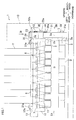
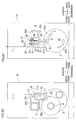
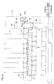
- Fig. 1 is an elevation of a winder of the present embodiment.
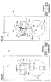
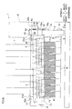
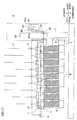
- Fig. 2A shows the winder of Fig. 1 viewed in the direction of the arrow IIA.
- Fig. 2B shows the winder of Fig. 1 viewed in the direction of the arrow IIB.
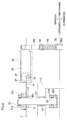
- Fig. 3A shows the winder of Fig. 1 viewed in the direction of the arrow III.
- Fig. 3B shows the winder of Fig. 3A from which the mounting member 22a and the swing axis 36 are removed.
- Fig. 4 is a cross section taken along the IV-IV line of Fig. 3A . It is noted that, in Fig.
- a part of a base 10 of the winder 1 is indicated by a two-dot chain line to show the components inside the part indicated by the two-dot chain line.
- the position of the mounting member 22a is indicated by a two-dot chain line for easily understanding the positional relations of the components.
- the winder 1 includes components such as a base 10, two bobbin holders 2 attached to the base 10, a turret table 3, a contact pressure applying mechanism 4, and a tilt mechanism 5.
- Each of the two bobbin holders 2 is a substantially column shaped member cantilevered at the turret table 3.
- a plurality of substantially cylindrical bobbins B are attached to each bobbin holder 2 .
- Each bobbin holder 2 is rotated about a rotation axis 2a by an unillustrated motor, thereby yarns Y are wound onto the bobbins B attached to the bobbin holder 2 as described later.
- traverse units 7 are provided above the bobbins B attached to the bobbin holders 2, traverse units 7 are provided above the bobbins B attached to the bobbin holders 2, traverse units 7 are provided above the bobbins B attached to the bobbin holders 2, traverse units 7 are provided above each traverse unit 7 is provided a yarn guide 8. The yarns Y are therefore wound onto the bobbins B while being traversed on these yarn guides 8 in the crosswise directions by the traverse units 7.
- the traverse units 7 and the yarn guides 8 are provided on a later-described supporting
- the turret table 3 is a substantially circular plate and cantilevers the two bobbin holders 2 as described above and moves these bobbin holders 2 as the turret table 3 rotates about a rotation axis 3a which is in parallel to the axes of the bobbin holders 2.
- the positions of the two bobbin holders 2 are interchangeable. It is therefore possible to continuously wind yarns in such a way that the bobbins B attached to one bobbin holder 2 are replaced with new ones while yarns are wound onto the bobbins B attached to the other bobbin holder 2.
- the turret table 3 rotates during the winding of the yarns Y onto the bobbin B, in accordance with the increase in the amount of wound yarns Y.
- the contact pressure applying mechanism 4 includes components such as a contact roller 11 and a supporting member 12.
- the contact roller 11 extends substantially in parallel to the bobbin holders 2, and contacts the outer circumference of each bobbin holder 2 attached to one of the two bobbin holders 2, which is at a winding position. With this, a contact pressure is applied to the bobbins B by the contact roller 11, when the yarn Y are wound thereon.
- the supporting member 12 rotatably supports the both ends of the contact roller 11. At around the both ends of the supporting member 12, linear motion bearings 19 are provided, respectively. Into the linear motion bearings 19 are inserted vertically-extending guide shafts 13. The supporting member 12 is elevatable by an unillustrated elevator mechanism. As the supporting member 12 is vertically moved, the supporting member 12 and the contact roller 11 are also vertically moved along the guide shafts 13.
- Each guide shaft 13 is inserted into linear motion bearings 21a and 21b at the respective ends.
- the linear motion bearings 21a and 21b are attached to mounting members 22a and 22b fixed to the frame 6, respectively.
- Each of the linear motion bearings 21a and 21b has an internal diameter slightly larger than the diameter of each guide shaft 13. Between the linear motion bearing 21a and the guide shaft 13 inserted thereto, an O-ring 23 is provided. Similarly, between the linear motion bearing 21b and the guide shaft 13 inserted thereto, an O-ring 23 is provided. With this arrangement, the guide shafts 13 are swingable with respect to the linear motion bearings 21a and 21b fixed to the frame 6 (mounting members 22a and 22b).
- the tilt mechanism 5 is a mechanism for tilting the contact roller 11, and includes components such as cams 31, a cam rod 32, a force multiplying arm 33, a tie rod 34, and a tilt arm 35.
- the two cams 31 are provided on the side face of the turret table 3 to correspond to the respective bobbin holders 2.
- Each cam 31 extends along the circumferential direction of the turret table 3 as shown in Fig. 2B .
- the outer circumference of each cam 31, i.e. the cam surface 31a is arranged to be away from the rotation axis 3a of the turret table 3, toward the upstream in the clockwise direction in Fig. 2B .
- the cam rod 32 has at its lower end portion a roller 41 which contacts the cam surface 31a, and the upper end portion of the cam rod 32 is connected to the force multiplying arm 33.
- the cam rod 32 further includes a rod forming member 32a having the roller 41 and a rod forming member 32b connected to the force multiplying arm 33, and these two rod forming members 32a and 32b are vertically movable relative to each other.
- a spring 42 is provided between the rod forming member 32a and the rod forming member 32b. As a bolt 43 provided immediately above the spring 42 of the rod forming member 32b is tightened, the spring 42 is compressed.
- the spring 42 may not be provided. In such a case, a single component substitutes for the two rod forming members 32a and 32b of the cam rod 32.
- the force multiplying arm 33 is a substantially rectangular plate whose one end is attached to the cam rod 32 whereas the other end is attached to a swing axis 36 inserted into a bearing 37, so as to be swingable about the swing axis 36.
- a mounting shaft 38 is attached for mounting the tie rod 34.
- the tie rod 34 is mounted to be closer to the center of the swing axis 36 than the cam rod 32.
- the tie rod 34 is mounted between the force multiplying arm 33 and the tilt arm 35 to connect the force multiplying arm 33 with the tilt arm 35.
- the bearing 37 to which the swing axis 36 is inserted is fixed, in front of the tie rod 34, to a mounting plate 39 which is substantially C-shaped to sandwich the tie rod 34 from the front and rear sides.
- the mounting plate 39 is fixed to the frame 6 on the side opposite to the side where the bearing 37 is fixed, over the tie rod 34.
- a swing axis and a bearing similar to the swing axis 36 and the bearing 37 are provided at the portion where the frame 6 is fixed to the mounting plate 39. This swing axis is attached to the end of the mounting shaft 38 which end is opposite to the swing axis 36.
- the tilt arm 35 is a plate extending in the front-back directions, and is swingably supported at its substantially central portion by the swing axis 24 which is provided on the mounting member 22a.
- the tilt arm 35 is attached to the tie rod 34 at the trailing end portion, whereas a through hole 35a is formed at the leading end portion. To the through hole 35a is inserted the above-described guide shaft 13.
- Fig. 5 to Fig. 9 show the states during the yarn winding and are equivalent to Fig. 2 , Fig. 4 , Fig. 3B , and Fig. 1 , respectively.
- yarns Y When yarns Y are wound onto the bobbins B in the winder 1, yarns Y produced by an unillustrated spinning apparatus above the winder 1 are placed onto the bobbins B. As the bobbin holder 2 is rotated in this state, the yarns Y are wound onto the bobbins B while a contact pressure is applied to the bobbins B.
- each bobbin B gradually increases in accordance with the increase in the amount of the wound yarns Y. Taking into consideration of this, it is necessary to gradually increase the distance between the bobbin holder 2 and the contact roller 11.
- the supporting member 12 is not moved (i.e. the contact roller 11 is retained at a predetermined position) in the present embodiment.
- the distance between the bobbin holder 2 and the contact roller 11 is gradually increased by rotating the turret table 3 in the direction away from the contact roller 11 (i.e. the anticlockwise direction in Fig. 5A and the clockwise direction in Fig. 5B ) as the amount of yarns Y wound onto the bobbins B increases.
- each cam 31 is arranged so that the cam surface 31a is away from the rotation axis 3a of the turret table 3, toward the upstream in the clockwise direction in Fig. 2B . For this reason, as each cam 31 rotates, the cam rod 32 contacting the cam surface 31a of the cam 31 is pushed upward by the cam 31 as indicated by the arrow a.
- the force multiplying arm 33 rotates anticlockwise about the swing axis 36, thereby pulling the tie rod 34 attached to the force multiplying arm 33 toward the force multiplying arm 33 (i.e. rightward in the figure) as indicated by the arrow b.
- the tie rod 34 since in the force multiplying arm 33 the tie rod 34 is attached to be closer to the swing axis 36 than the cam rod 32 as described above, the moving distance of the tie rod 34 in response to the rotation of the force multiplying arm 33 caused by the movement of the cam rod 32 is shorter than the moving distance of the cam rod 32. Therefore, the force exerted from the force multiplying arm 33 to the tie rod 34 is greater than the force exerted from the cam rod 32 to the force multiplying arm 33.
- the trailing end portion of the tilt arm 35 connected to the tie rod 34 is also pulled toward the force multiplying arm 33 as indicated by the arrow b, with the result that the tilt arm 35 rotates clockwise about the swing axis 24.
- This rotation of the tilt arm 35 causes the leading end portion of the tilt arm 35, to which the guide shaft 13 inserted, to move in the direction (leftward in the figure) opposite to the movement of the trailing end portion, as indicated by the arrow c.
- the guide shaft 13 is pressed by the tilt arm 35 (i.e. the wall of the through hole 35a) and tilted. Therefore the supporting member 12 elevatable along the guide shaft 13 and the contact roller 11 supported by the supporting member 12 are tilted. In this state, the contact roller 11 is tilted in such a way that the part thereof corresponding to the leading end side of the bobbin holder 2 is positioned downward (in Fig. 8 , the tilting angle immediately before the completion of the winding is denoted as ⁇ ).
- the turret table 3 is the moving member of the present invention
- the tilt mechanism 5 constituted by the cams 31, the cam rod 32, the force multiplying arm 33,the tie rod 34, and the tilt arm 35 is mechanically interlocked with the turret table 3.
- the tilt mechanism 5 tilts the contact roller 11 by using the rotation of the turret table 3 which is the moving member.
- the tilting angle of the contact roller 11 increases.
- the bobbin holder 2 is warped downward toward the leading end remote from the part supported by the turret table 3, on account of the weight of the yarns Y.
- the degree of this warping increases as the amount of yarns Y wound onto the bobbins B increases.
- the contact roller 11 is not tilted, the bobbin B attached at the most leading end side of the bobbin holder 2 receives the least contact pressure from the contact roller 11, with the result that the diameters of the bobbins B are irregular between the left ones and the right ones when the winding of the yarns Y is completed.
- the contact roller 11 is tilted so that the part corresponding to the leading end side of the bobbin holder 2 is positioned downward, with the result that the bobbin holder 2 and the contact roller 11 are maintained to be more or less in parallel to each other and the distance between them is constant at all parts.
- the contact pressure between the contact roller 11 and each bobbin B is therefore constant and the diameter of each bobbin after the winding is constant.
- the tilt mechanism 5 mechanically interlocked with the turret table 3 tilts the contact roller 11 by transferring, to the guide shaft 13, the rotation of the turret table 3 which rotates in accordance with the increase in the amount of yarns Y wound onto the bobbins B. Because of this arrangement, even if a part of the tilt mechanism 5 is broken, merely the rotation of the turret table 3 is not transferred to the guide shaft 13 (i.e. the tilt mechanism 5 is no longer mechanically interlocked with the turret table 3) and the contact roller 11 is not tilted any more, and hence the contact roller 11 is maintained to have the position immediately before the breakdown of the tilt mechanism 5.
- the contact roller 11 has a certain amount of weight and hence a sufficiently large force is required to tilt the contact roller 11.
- the force applied from the force multiplying arm 33 to the tie rod 34 is larger than the force applied from the cam rod 32 to the force multiplying arm 33 as described above, it is possible to tilt the heavy contact roller 11 even if the force by which the cams 31 push the cam rod 32 is not so large.
- the rotation of the turret table 3 may be transferred to the guide shaft 13 by using a different mechanism.
- the contact roller 11 may be directly tilted without tilting the guide shaft 13 and the supporting member 12.
- the embodiment above is arranged so that, since the supporting member 12 supporting the contact roller 11 is elevatable, the contact roller 11 is caused to contact the bobbins B when the yarns Y are wound whereas the contact roller 11 is moved away from the bobbin holder 2 in cases such as the placement of the yarns.
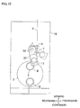
- a different structure may be used for moving the contact roller 11 to contact or to be away from the bobbin holder 2.
- the supporting member 51 supporting the contact roller 11 is provided with a swing axis 52.
- the respective ends of the swing axis 52 are inserted into bearings 53a and 53b, thereby allowing the supporting member 51 to be swingable about the swing axis 52.
- the contact roller 11 is moved between the position which is indicated by the full line in Fig. 10 and where the contact roller 11 contacts the bobbins B and the position which is indicated by the two-dot chain line in Fig. 10 and where the contact roller 11 is away from the bobbin holder 2.
- the bearings 53a and 53b are ball bearings, and the swing axis 52 is arranged to be swingable with respect to the bearings 53a and 53b.
- the bearing 53a is attached to an unillustrated frame or the like which is fixed to the base 10, whereas the bearing 53b is attached to the arm 54.
- the arm 54 is supported to be swingable about a swing axis 55 at an end thereof.
- This arm 54 is provided with the bearing 53b substantially at the center thereof, and is connected to the cam rod 32 at the end opposite to the swing axis 55.
- the arm 54 is arranged so that the bearing 53b is closer to the swing axis 55 than the cam rod 32.
- the turret table 3 rotates as the amount of yarns Y wound onto the bobbins B increases, wit the result that the cams 31 rotate and the cam rod 32 is pressed by the cams 31 and moved upward.
- the arm 54 is swung about the swing axis 55 and the bearing 53b attached to the arm 54 is pushed upward. This tilts the swing axis 52 which is inserted into the bearings 53a and 53b, the supporting member 51 supported by the swing axis 52, and the contact roller 11 supported by the supporting member 51.
- the contact roller 11 is tilted so that the part corresponding to the leading end side of the bobbin holder 2 is positioned downward.
- the cams 31, the cam rod 32, and the arm 54 for tilting the contact roller 11 are the tilt mechanism of the present invention.
- the bearing 53b is attached to be closer to the swing axis 55 than the cam rod 32, and hence the moving distance of the bearing 53b in response to the rotation of the arm 54 is shorter than the moving distance of the cam rod 32. Therefore the force applied from the arm 54 to the bearing 53b is larger than the force applied from the cam rod 32 to the arm 54, and hence the heavy contact roller 11 is tilted even if the force by which the cams 31 push the cam rod 32 is not so large.
- the embodiment above is arranged so that the distance between the bobbin holder 2 and the contact roller 11 is gradually increased by rotating the turret table 3 in accordance with the increase in the amount of yarns Y wound onto the bobbins B, and the contact roller 11 is tilted by transferring the rotation of the turret table 3 thereto.
- the present invention is not limited to this arrangement.
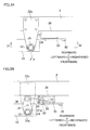
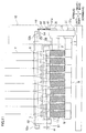
- a linear motion bearing 62 is provided at one end of a supporting member 61 supporting the both ends of the contact roller 11.
- the winder of the modification 2 is provided with a guide shaft 63 which is fixed to an unillustrated frame of the base 10 and extends in the vertical directions.
- the guide shaft 63 is inserted into the linear motion bearing 62.
- 0-rings 64 are provided between the respective ends of the linear motion bearing 62 and the supporting member 61. This allows the supporting member 61 and the contact roller 11 to be swingable with respect to the guide shaft 63 fixed to the base 10.
- a roller 61a At an end of the supporting member 61 is provided a roller 61a. Furthermore, beside the supporting member 61 is provided a tilt mechanism 65 fixed to the unillustrated frame of the base 10, to correspond to the roller 61a.
- the tilt mechanism 65 has a vertically extending groove 66. To this groove 66, the roller 61a of the supporting member 61 is fit. The roller 61a vertically moves along the groove 66 as the supporting member 61 vertically moves along the guide shaft 63. Furthermore, inside the groove 66 is provided a guide member 67 which contacts the leading end portion of the roller 61a. The guide member 67 is tilted with respect to the vertical directions such that the guide surface 67a (guide) contacting the leading end portion of the roller 61a is closer to the supporting member 61 (i.e. is tilted leftward) toward the upper end of the surface.
- the turret table 3 does not rotate when the amount of yarns Y wound onto the bobbins B is increased. Instead, the contact roller 11 and the supporting member 61 are pressed upward by the bobbins B having larger diameters because of the winding of the yarns Y and move along the guide shaft 63, and this increases the distance between the bobbin holder 2 and the contact roller 11.
- the contact roller 11 and the supporting member 61 are pushed and moved upward by the bobbins B and the roller 61a is moved upward along the groove 66 as shown in Fig. 13 .
- the roller 61a is guided along the guide surface 67a of the guide member 67 and hence the supporting member 61 and the contact roller 11 are tilted.
- the contact roller 11 is tilted so that the part corresponding to the leading end side of the bobbin holder 2 is positioned downward.
- the contact roller 11 is equivalent to the moving member of the present invention and the contact roller 11 is mechanically interlocked with the tilt mechanism 65 such that the leading end portion of the roller 61a of the supporting member 61 supporting the contact roller 11 contacts the guide member 67 (guide surface 67a). Furthermore, the tilt mechanism 65 tilts the contact roller 11 by utilizing the movement of the contact roller 11 caused by the increase in the amount of yarns Y wound onto the bobbins B.
- the contact roller 11 may be tilted by another tilt mechanism which is mechanically interlocked with the contact roller 11 and utilizes the movement of the contact roller 11 in a different manner.
- the tilt mechanism tilts the contact roller 11 by utilizing the rotation of the turret table 3 or the movement of the contact roller 11, the present invention is not limited to this.
- the tilt mechanism may be mechanically interlocked with this moving member and tilt the contact roller 11 by utilizing the movement of the moving member.
Landscapes
- Replacing, Conveying, And Pick-Finding For Filamentary Materials (AREA)
- Winding Filamentary Materials (AREA)
Applications Claiming Priority (1)
| Application Number | Priority Date | Filing Date | Title |
|---|---|---|---|
| JP2010129624A JP5529632B2 (ja) | 2010-06-07 | 2010-06-07 | 巻取機 |
Publications (3)
| Publication Number | Publication Date |
|---|---|
| EP2392532A2 true EP2392532A2 (de) | 2011-12-07 |
| EP2392532A3 EP2392532A3 (de) | 2013-02-20 |
| EP2392532B1 EP2392532B1 (de) | 2014-03-05 |
Family
ID=44312319
Family Applications (1)
| Application Number | Title | Priority Date | Filing Date |
|---|---|---|---|
| EP20110166875 Active EP2392532B1 (de) | 2010-06-07 | 2011-05-20 | Wickler |
Country Status (3)
| Country | Link |
|---|---|
| EP (1) | EP2392532B1 (de) |
| JP (1) | JP5529632B2 (de) |
| CN (1) | CN102267652B (de) |
Cited By (4)
| Publication number | Priority date | Publication date | Assignee | Title |
|---|---|---|---|---|
| EP3357847A1 (de) * | 2017-02-06 | 2018-08-08 | TMT Machinery, Inc. | Garnaufwickler, vorrichtung zur aufnahme von gesponnenem garn und verfahren zur garneinfädelung im garnaufwickler |
| EP3412611A1 (de) * | 2017-06-06 | 2018-12-12 | TMT Machinery, Inc. | Garnwickler |
| WO2020126724A1 (de) | 2018-12-19 | 2020-06-25 | Oerlikon Textile Gmbh & Co. Kg | Aufspulmaschine |
| EP4349753A3 (de) * | 2020-11-27 | 2024-06-26 | TMT Machinery, Inc. | Garnwickler |
Families Citing this family (10)
| Publication number | Priority date | Publication date | Assignee | Title |
|---|---|---|---|---|
| JP5860348B2 (ja) * | 2012-06-19 | 2016-02-16 | Tmtマシナリー株式会社 | 紡糸巻取機 |
| CN102774703B (zh) * | 2012-07-31 | 2013-08-14 | 太仓仕禾线网制造有限公司 | 一种络丝机的卷纱装置 |
| CN102774704B (zh) * | 2012-07-31 | 2014-04-16 | 太仓仕禾线网制造有限公司 | 络丝机的卷纱装置 |
| JP6275972B2 (ja) * | 2013-08-23 | 2018-02-07 | Tmtマシナリー株式会社 | 繊維機械 |
| JP6512950B2 (ja) * | 2014-07-02 | 2019-05-15 | Tmtマシナリー株式会社 | 糸巻取装置、及び、紡糸引取装置 |
| CN104401799B (zh) * | 2014-11-03 | 2016-06-15 | 重庆晨宇机床制造有限公司 | 一种便于加载线筒的固定式纺织绕线机 |
| CN104444601A (zh) * | 2014-11-03 | 2015-03-25 | 宁波海曙信满贸易有限公司 | 一种便于加载线筒且易于维护的纺织绕线机 |
| CN104401809B (zh) * | 2014-11-03 | 2015-07-29 | 江苏银桥纺织科技有限公司 | 一种便于加载线筒的纺织绕线机及其操作方法 |
| CN104444575A (zh) * | 2014-11-03 | 2015-03-25 | 洪恒丰 | 一种便于加载线筒且可自动张紧的纺织绕线机 |
| DE102023001454A1 (de) | 2023-04-14 | 2024-10-17 | Oerlikon Textile Gmbh & Co. Kg | Vorrichtung zum Ausgleichen einer Belastungsbiegelinie einer Spulspindel |
Citations (1)
| Publication number | Priority date | Publication date | Assignee | Title |
|---|---|---|---|---|
| JPH08310723A (ja) | 1995-05-17 | 1996-11-26 | Murata Mach Ltd | 巻取機 |
Family Cites Families (6)
| Publication number | Priority date | Publication date | Assignee | Title |
|---|---|---|---|---|
| JPS5255746A (en) * | 1975-10-30 | 1977-05-07 | Mitsubishi Heavy Ind Ltd | Build up process of high speed winder driving roll |
| US4394985A (en) * | 1979-07-10 | 1983-07-26 | Rieter Machine Works Limited | Winding apparatus for threads or yarns |
| JPS61273471A (ja) * | 1985-05-24 | 1986-12-03 | Mitsubishi Heavy Ind Ltd | 高速繊条巻取機 |
| JPH0346969A (ja) * | 1989-07-14 | 1991-02-28 | Murata Mach Ltd | 紡糸巻取機 |
| CH694370A5 (de) * | 1999-02-03 | 2004-12-15 | Barmag Barmer Maschf | Aufspulvorrichtung. |
| US6622956B2 (en) * | 2000-11-08 | 2003-09-23 | Murata Kikai Kabushiki Kaisha | Take-up winder |
-
2010
- 2010-06-07 JP JP2010129624A patent/JP5529632B2/ja active Active
-
2011
- 2011-05-20 EP EP20110166875 patent/EP2392532B1/de active Active
- 2011-05-27 CN CN201110139813.5A patent/CN102267652B/zh active Active
Patent Citations (1)
| Publication number | Priority date | Publication date | Assignee | Title |
|---|---|---|---|---|
| JPH08310723A (ja) | 1995-05-17 | 1996-11-26 | Murata Mach Ltd | 巻取機 |
Cited By (5)
| Publication number | Priority date | Publication date | Assignee | Title |
|---|---|---|---|---|
| EP3357847A1 (de) * | 2017-02-06 | 2018-08-08 | TMT Machinery, Inc. | Garnaufwickler, vorrichtung zur aufnahme von gesponnenem garn und verfahren zur garneinfädelung im garnaufwickler |
| EP3412611A1 (de) * | 2017-06-06 | 2018-12-12 | TMT Machinery, Inc. | Garnwickler |
| WO2020126724A1 (de) | 2018-12-19 | 2020-06-25 | Oerlikon Textile Gmbh & Co. Kg | Aufspulmaschine |
| CN113195390A (zh) * | 2018-12-19 | 2021-07-30 | 欧瑞康纺织有限及两合公司 | 卷绕机 |
| EP4349753A3 (de) * | 2020-11-27 | 2024-06-26 | TMT Machinery, Inc. | Garnwickler |
Also Published As
| Publication number | Publication date |
|---|---|
| JP2011255979A (ja) | 2011-12-22 |
| EP2392532B1 (de) | 2014-03-05 |
| CN102267652A (zh) | 2011-12-07 |
| JP5529632B2 (ja) | 2014-06-25 |
| CN102267652B (zh) | 2015-07-15 |
| EP2392532A3 (de) | 2013-02-20 |
Similar Documents
| Publication | Publication Date | Title |
|---|---|---|
| EP2392532B1 (de) | Wickler | |
| JP5615743B2 (ja) | 紡糸巻取機 | |
| CN100404401C (zh) | 横动设备 | |
| EP2423143B1 (de) | Verwendung einer Garnwicklungsvorrichtung | |
| JP4990681B2 (ja) | 糸条巻取機 | |
| EP2548830B1 (de) | Spinnaufwickler | |
| CN101439817A (zh) | 双滚筒绕线机 | |
| KR101898760B1 (ko) | 비드링 권취장치 | |
| JP3868251B2 (ja) | 綾巻きパッケージを製造する繊維機械の作業箇所のための巻管供給器 | |
| RU2392214C1 (ru) | Раскладчик намоточного станка | |
| JP2002145527A (ja) | 特に敏感な巻取り材料用の巻取機 | |
| JP2012158436A (ja) | 糸巻取機 | |
| JP6116372B2 (ja) | パッケージフレーム用のロック手段を有する巻取り装置 | |
| TWI790374B (zh) | 絲捲繞機 | |
| CN109732016B (zh) | 弹簧绕制装置 | |
| EP3118148B1 (de) | Garnwickelvorrichtung | |
| WO2020031457A1 (ja) | 糸巻取機 | |
| CN113195390B (zh) | 卷绕机 | |
| CN223587611U (zh) | 一种摆臂式v托机构 | |
| JP4116751B2 (ja) | 線材供給部材と線材の巻線方法及びその装置 | |
| EP3006384B1 (de) | Spulentrennungsvorrichtung, abnahmewagen und garnwickelmaschine | |
| CN216632176U (zh) | 钢桶自动预卷机 | |
| JPS6194976A (ja) | 巻取装置 | |
| JP3690351B2 (ja) | 糸条巻取機及び糸条巻取方法 | |
| CN107682805B (zh) | 一种线轴的预放线装置及其方法 |
Legal Events
| Date | Code | Title | Description |
|---|---|---|---|
| AK | Designated contracting states |
Kind code of ref document: A2 Designated state(s): AL AT BE BG CH CY CZ DE DK EE ES FI FR GB GR HR HU IE IS IT LI LT LU LV MC MK MT NL NO PL PT RO RS SE SI SK SM TR |
|
| AX | Request for extension of the european patent |
Extension state: BA ME |
|
| PUAI | Public reference made under article 153(3) epc to a published international application that has entered the european phase |
Free format text: ORIGINAL CODE: 0009012 |
|
| PUAL | Search report despatched |
Free format text: ORIGINAL CODE: 0009013 |
|
| AK | Designated contracting states |
Kind code of ref document: A3 Designated state(s): AL AT BE BG CH CY CZ DE DK EE ES FI FR GB GR HR HU IE IS IT LI LT LU LV MC MK MT NL NO PL PT RO RS SE SI SK SM TR |
|
| AX | Request for extension of the european patent |
Extension state: BA ME |
|
| RIC1 | Information provided on ipc code assigned before grant |
Ipc: B65H 54/52 20060101AFI20130111BHEP Ipc: B65H 67/048 20060101ALI20130111BHEP |
|
| 17P | Request for examination filed |
Effective date: 20130523 |
|
| RBV | Designated contracting states (corrected) |
Designated state(s): AL AT BE BG CH CY CZ DE DK EE ES FI FR GB GR HR HU IE IS IT LI LT LU LV MC MK MT NL NO PL PT RO RS SE SI SK SM TR |
|
| GRAP | Despatch of communication of intention to grant a patent |
Free format text: ORIGINAL CODE: EPIDOSNIGR1 |
|
| INTG | Intention to grant announced |
Effective date: 20131001 |
|
| GRAS | Grant fee paid |
Free format text: ORIGINAL CODE: EPIDOSNIGR3 |
|
| GRAA | (expected) grant |
Free format text: ORIGINAL CODE: 0009210 |
|
| AK | Designated contracting states |
Kind code of ref document: B1 Designated state(s): AL AT BE BG CH CY CZ DE DK EE ES FI FR GB GR HR HU IE IS IT LI LT LU LV MC MK MT NL NO PL PT RO RS SE SI SK SM TR |
|
| REG | Reference to a national code |
Ref country code: GB Ref legal event code: FG4D |
|
| REG | Reference to a national code |
Ref country code: CH Ref legal event code: EP |
|
| REG | Reference to a national code |
Ref country code: AT Ref legal event code: REF Ref document number: 654722 Country of ref document: AT Kind code of ref document: T Effective date: 20140315 |
|
| RIN2 | Information on inventor provided after grant (corrected) |
Inventor name: SUGIYAMA, KENJI |
|
| REG | Reference to a national code |
Ref country code: IE Ref legal event code: FG4D |
|
| REG | Reference to a national code |
Ref country code: DE Ref legal event code: R096 Ref document number: 602011005163 Country of ref document: DE Effective date: 20140417 |
|
| RIN2 | Information on inventor provided after grant (corrected) |
Inventor name: SUGIYAMA, KENJI |
|
| REG | Reference to a national code |
Ref country code: AT Ref legal event code: MK05 Ref document number: 654722 Country of ref document: AT Kind code of ref document: T Effective date: 20140305 |
|
| REG | Reference to a national code |
Ref country code: NL Ref legal event code: VDEP Effective date: 20140305 |
|
| PG25 | Lapsed in a contracting state [announced via postgrant information from national office to epo] |
Ref country code: LT Free format text: LAPSE BECAUSE OF FAILURE TO SUBMIT A TRANSLATION OF THE DESCRIPTION OR TO PAY THE FEE WITHIN THE PRESCRIBED TIME-LIMIT Effective date: 20140305 Ref country code: NO Free format text: LAPSE BECAUSE OF FAILURE TO SUBMIT A TRANSLATION OF THE DESCRIPTION OR TO PAY THE FEE WITHIN THE PRESCRIBED TIME-LIMIT Effective date: 20140605 |
|
| REG | Reference to a national code |
Ref country code: LT Ref legal event code: MG4D |
|
| PG25 | Lapsed in a contracting state [announced via postgrant information from national office to epo] |
Ref country code: AT Free format text: LAPSE BECAUSE OF FAILURE TO SUBMIT A TRANSLATION OF THE DESCRIPTION OR TO PAY THE FEE WITHIN THE PRESCRIBED TIME-LIMIT Effective date: 20140305 Ref country code: FI Free format text: LAPSE BECAUSE OF FAILURE TO SUBMIT A TRANSLATION OF THE DESCRIPTION OR TO PAY THE FEE WITHIN THE PRESCRIBED TIME-LIMIT Effective date: 20140305 Ref country code: CY Free format text: LAPSE BECAUSE OF FAILURE TO SUBMIT A TRANSLATION OF THE DESCRIPTION OR TO PAY THE FEE WITHIN THE PRESCRIBED TIME-LIMIT Effective date: 20140305 Ref country code: SE Free format text: LAPSE BECAUSE OF FAILURE TO SUBMIT A TRANSLATION OF THE DESCRIPTION OR TO PAY THE FEE WITHIN THE PRESCRIBED TIME-LIMIT Effective date: 20140305 |
|
| PG25 | Lapsed in a contracting state [announced via postgrant information from national office to epo] |
Ref country code: HR Free format text: LAPSE BECAUSE OF FAILURE TO SUBMIT A TRANSLATION OF THE DESCRIPTION OR TO PAY THE FEE WITHIN THE PRESCRIBED TIME-LIMIT Effective date: 20140305 Ref country code: RS Free format text: LAPSE BECAUSE OF FAILURE TO SUBMIT A TRANSLATION OF THE DESCRIPTION OR TO PAY THE FEE WITHIN THE PRESCRIBED TIME-LIMIT Effective date: 20140305 Ref country code: LV Free format text: LAPSE BECAUSE OF FAILURE TO SUBMIT A TRANSLATION OF THE DESCRIPTION OR TO PAY THE FEE WITHIN THE PRESCRIBED TIME-LIMIT Effective date: 20140305 |
|
| PG25 | Lapsed in a contracting state [announced via postgrant information from national office to epo] |
Ref country code: EE Free format text: LAPSE BECAUSE OF FAILURE TO SUBMIT A TRANSLATION OF THE DESCRIPTION OR TO PAY THE FEE WITHIN THE PRESCRIBED TIME-LIMIT Effective date: 20140305 Ref country code: CZ Free format text: LAPSE BECAUSE OF FAILURE TO SUBMIT A TRANSLATION OF THE DESCRIPTION OR TO PAY THE FEE WITHIN THE PRESCRIBED TIME-LIMIT Effective date: 20140305 Ref country code: BG Free format text: LAPSE BECAUSE OF FAILURE TO SUBMIT A TRANSLATION OF THE DESCRIPTION OR TO PAY THE FEE WITHIN THE PRESCRIBED TIME-LIMIT Effective date: 20140605 Ref country code: IS Free format text: LAPSE BECAUSE OF FAILURE TO SUBMIT A TRANSLATION OF THE DESCRIPTION OR TO PAY THE FEE WITHIN THE PRESCRIBED TIME-LIMIT Effective date: 20140705 Ref country code: NL Free format text: LAPSE BECAUSE OF FAILURE TO SUBMIT A TRANSLATION OF THE DESCRIPTION OR TO PAY THE FEE WITHIN THE PRESCRIBED TIME-LIMIT Effective date: 20140305 Ref country code: BE Free format text: LAPSE BECAUSE OF FAILURE TO SUBMIT A TRANSLATION OF THE DESCRIPTION OR TO PAY THE FEE WITHIN THE PRESCRIBED TIME-LIMIT Effective date: 20140305 Ref country code: RO Free format text: LAPSE BECAUSE OF FAILURE TO SUBMIT A TRANSLATION OF THE DESCRIPTION OR TO PAY THE FEE WITHIN THE PRESCRIBED TIME-LIMIT Effective date: 20140305 |
|
| PG25 | Lapsed in a contracting state [announced via postgrant information from national office to epo] |
Ref country code: PL Free format text: LAPSE BECAUSE OF FAILURE TO SUBMIT A TRANSLATION OF THE DESCRIPTION OR TO PAY THE FEE WITHIN THE PRESCRIBED TIME-LIMIT Effective date: 20140305 Ref country code: SK Free format text: LAPSE BECAUSE OF FAILURE TO SUBMIT A TRANSLATION OF THE DESCRIPTION OR TO PAY THE FEE WITHIN THE PRESCRIBED TIME-LIMIT Effective date: 20140305 Ref country code: ES Free format text: LAPSE BECAUSE OF FAILURE TO SUBMIT A TRANSLATION OF THE DESCRIPTION OR TO PAY THE FEE WITHIN THE PRESCRIBED TIME-LIMIT Effective date: 20140305 |
|
| REG | Reference to a national code |
Ref country code: DE Ref legal event code: R097 Ref document number: 602011005163 Country of ref document: DE |
|
| PG25 | Lapsed in a contracting state [announced via postgrant information from national office to epo] |
Ref country code: LU Free format text: LAPSE BECAUSE OF FAILURE TO SUBMIT A TRANSLATION OF THE DESCRIPTION OR TO PAY THE FEE WITHIN THE PRESCRIBED TIME-LIMIT Effective date: 20140520 Ref country code: PT Free format text: LAPSE BECAUSE OF FAILURE TO SUBMIT A TRANSLATION OF THE DESCRIPTION OR TO PAY THE FEE WITHIN THE PRESCRIBED TIME-LIMIT Effective date: 20140707 |
|
| REG | Reference to a national code |
Ref country code: CH Ref legal event code: PL |
|
| PLBE | No opposition filed within time limit |
Free format text: ORIGINAL CODE: 0009261 |
|
| STAA | Information on the status of an ep patent application or granted ep patent |
Free format text: STATUS: NO OPPOSITION FILED WITHIN TIME LIMIT |
|
| PG25 | Lapsed in a contracting state [announced via postgrant information from national office to epo] |
Ref country code: LI Free format text: LAPSE BECAUSE OF NON-PAYMENT OF DUE FEES Effective date: 20140531 Ref country code: MC Free format text: LAPSE BECAUSE OF FAILURE TO SUBMIT A TRANSLATION OF THE DESCRIPTION OR TO PAY THE FEE WITHIN THE PRESCRIBED TIME-LIMIT Effective date: 20140305 Ref country code: DK Free format text: LAPSE BECAUSE OF FAILURE TO SUBMIT A TRANSLATION OF THE DESCRIPTION OR TO PAY THE FEE WITHIN THE PRESCRIBED TIME-LIMIT Effective date: 20140305 Ref country code: CH Free format text: LAPSE BECAUSE OF NON-PAYMENT OF DUE FEES Effective date: 20140531 |
|
| 26N | No opposition filed |
Effective date: 20141208 |
|
| REG | Reference to a national code |
Ref country code: IE Ref legal event code: MM4A |
|
| REG | Reference to a national code |
Ref country code: FR Ref legal event code: ST Effective date: 20150130 |
|
| REG | Reference to a national code |
Ref country code: DE Ref legal event code: R097 Ref document number: 602011005163 Country of ref document: DE Effective date: 20141208 |
|
| PG25 | Lapsed in a contracting state [announced via postgrant information from national office to epo] |
Ref country code: IT Free format text: LAPSE BECAUSE OF FAILURE TO SUBMIT A TRANSLATION OF THE DESCRIPTION OR TO PAY THE FEE WITHIN THE PRESCRIBED TIME-LIMIT Effective date: 20140305 |
|
| PG25 | Lapsed in a contracting state [announced via postgrant information from national office to epo] |
Ref country code: IE Free format text: LAPSE BECAUSE OF NON-PAYMENT OF DUE FEES Effective date: 20140520 |
|
| PG25 | Lapsed in a contracting state [announced via postgrant information from national office to epo] |
Ref country code: SI Free format text: LAPSE BECAUSE OF FAILURE TO SUBMIT A TRANSLATION OF THE DESCRIPTION OR TO PAY THE FEE WITHIN THE PRESCRIBED TIME-LIMIT Effective date: 20140305 Ref country code: FR Free format text: LAPSE BECAUSE OF NON-PAYMENT OF DUE FEES Effective date: 20140602 |
|
| GBPC | Gb: european patent ceased through non-payment of renewal fee |
Effective date: 20150520 |
|
| PG25 | Lapsed in a contracting state [announced via postgrant information from national office to epo] |
Ref country code: MT Free format text: LAPSE BECAUSE OF FAILURE TO SUBMIT A TRANSLATION OF THE DESCRIPTION OR TO PAY THE FEE WITHIN THE PRESCRIBED TIME-LIMIT Effective date: 20140305 |
|
| PG25 | Lapsed in a contracting state [announced via postgrant information from national office to epo] |
Ref country code: GB Free format text: LAPSE BECAUSE OF NON-PAYMENT OF DUE FEES Effective date: 20150520 Ref country code: SM Free format text: LAPSE BECAUSE OF FAILURE TO SUBMIT A TRANSLATION OF THE DESCRIPTION OR TO PAY THE FEE WITHIN THE PRESCRIBED TIME-LIMIT Effective date: 20140305 |
|
| PG25 | Lapsed in a contracting state [announced via postgrant information from national office to epo] |
Ref country code: GR Free format text: LAPSE BECAUSE OF FAILURE TO SUBMIT A TRANSLATION OF THE DESCRIPTION OR TO PAY THE FEE WITHIN THE PRESCRIBED TIME-LIMIT Effective date: 20140606 |
|
| PG25 | Lapsed in a contracting state [announced via postgrant information from national office to epo] |
Ref country code: HU Free format text: LAPSE BECAUSE OF FAILURE TO SUBMIT A TRANSLATION OF THE DESCRIPTION OR TO PAY THE FEE WITHIN THE PRESCRIBED TIME-LIMIT; INVALID AB INITIO Effective date: 20110520 Ref country code: TR Free format text: LAPSE BECAUSE OF FAILURE TO SUBMIT A TRANSLATION OF THE DESCRIPTION OR TO PAY THE FEE WITHIN THE PRESCRIBED TIME-LIMIT Effective date: 20140305 |
|
| PG25 | Lapsed in a contracting state [announced via postgrant information from national office to epo] |
Ref country code: MK Free format text: LAPSE BECAUSE OF FAILURE TO SUBMIT A TRANSLATION OF THE DESCRIPTION OR TO PAY THE FEE WITHIN THE PRESCRIBED TIME-LIMIT Effective date: 20140305 |
|
| PG25 | Lapsed in a contracting state [announced via postgrant information from national office to epo] |
Ref country code: AL Free format text: LAPSE BECAUSE OF FAILURE TO SUBMIT A TRANSLATION OF THE DESCRIPTION OR TO PAY THE FEE WITHIN THE PRESCRIBED TIME-LIMIT Effective date: 20140305 |
|
| P01 | Opt-out of the competence of the unified patent court (upc) registered |
Effective date: 20230426 |
|
| PGFP | Annual fee paid to national office [announced via postgrant information from national office to epo] |
Ref country code: DE Payment date: 20250520 Year of fee payment: 15 |