EP2386517A1 - Kranausleger, insbesondere Mobilkranausleger, mit vorgespannten Zugelementen - Google Patents
Kranausleger, insbesondere Mobilkranausleger, mit vorgespannten Zugelementen Download PDFInfo
- Publication number
- EP2386517A1 EP2386517A1 EP11160100A EP11160100A EP2386517A1 EP 2386517 A1 EP2386517 A1 EP 2386517A1 EP 11160100 A EP11160100 A EP 11160100A EP 11160100 A EP11160100 A EP 11160100A EP 2386517 A1 EP2386517 A1 EP 2386517A1
- Authority
- EP
- European Patent Office
- Prior art keywords
- tension elements
- part according
- jib part
- boom
- sensors
- Prior art date
- Legal status (The legal status is an assumption and is not a legal conclusion. Google has not performed a legal analysis and makes no representation as to the accuracy of the status listed.)
- Granted
Links
- 239000000835 fiber Substances 0.000 claims description 12
- 238000007493 shaping process Methods 0.000 claims description 9
- 239000011159 matrix material Substances 0.000 claims description 2
- 230000036316 preload Effects 0.000 abstract 1
- 238000010276 construction Methods 0.000 description 12
- 239000000463 material Substances 0.000 description 12
- 239000010410 layer Substances 0.000 description 7
- 239000002131 composite material Substances 0.000 description 6
- 229910000831 Steel Inorganic materials 0.000 description 4
- 239000010959 steel Substances 0.000 description 4
- XAGFODPZIPBFFR-UHFFFAOYSA-N aluminium Chemical compound [Al] XAGFODPZIPBFFR-UHFFFAOYSA-N 0.000 description 3
- 229910052782 aluminium Inorganic materials 0.000 description 3
- 238000005452 bending Methods 0.000 description 3
- 238000004804 winding Methods 0.000 description 3
- 238000005299 abrasion Methods 0.000 description 2
- 230000003044 adaptive effect Effects 0.000 description 2
- 238000005253 cladding Methods 0.000 description 2
- 230000007423 decrease Effects 0.000 description 2
- 230000000694 effects Effects 0.000 description 2
- 230000007704 transition Effects 0.000 description 2
- 229920000049 Carbon (fiber) Polymers 0.000 description 1
- 241000446313 Lamella Species 0.000 description 1
- 230000006978 adaptation Effects 0.000 description 1
- 239000004411 aluminium Substances 0.000 description 1
- 238000004873 anchoring Methods 0.000 description 1
- 239000004917 carbon fiber Substances 0.000 description 1
- 230000015556 catabolic process Effects 0.000 description 1
- 239000011248 coating agent Substances 0.000 description 1
- 238000000576 coating method Methods 0.000 description 1
- 238000009826 distribution Methods 0.000 description 1
- 230000007613 environmental effect Effects 0.000 description 1
- 239000003365 glass fiber Substances 0.000 description 1
- 238000004519 manufacturing process Methods 0.000 description 1
- 238000000034 method Methods 0.000 description 1
- 238000012544 monitoring process Methods 0.000 description 1
- 230000000704 physical effect Effects 0.000 description 1
- 239000011241 protective layer Substances 0.000 description 1
- 230000003068 static effect Effects 0.000 description 1
- 239000012209 synthetic fiber Substances 0.000 description 1
- 229920002994 synthetic fiber Polymers 0.000 description 1
Images


Classifications
-
- B—PERFORMING OPERATIONS; TRANSPORTING
- B66—HOISTING; LIFTING; HAULING
- B66C—CRANES; LOAD-ENGAGING ELEMENTS OR DEVICES FOR CRANES, CAPSTANS, WINCHES, OR TACKLES
- B66C23/00—Cranes comprising essentially a beam, boom, or triangular structure acting as a cantilever and mounted for translatory of swinging movements in vertical or horizontal planes or a combination of such movements, e.g. jib-cranes, derricks, tower cranes
- B66C23/62—Constructional features or details
- B66C23/64—Jibs
-
- B—PERFORMING OPERATIONS; TRANSPORTING
- B66—HOISTING; LIFTING; HAULING
- B66C—CRANES; LOAD-ENGAGING ELEMENTS OR DEVICES FOR CRANES, CAPSTANS, WINCHES, OR TACKLES
- B66C23/00—Cranes comprising essentially a beam, boom, or triangular structure acting as a cantilever and mounted for translatory of swinging movements in vertical or horizontal planes or a combination of such movements, e.g. jib-cranes, derricks, tower cranes
- B66C23/62—Constructional features or details
- B66C23/64—Jibs
- B66C23/70—Jibs constructed of sections adapted to be assembled to form jibs or various lengths
-
- B—PERFORMING OPERATIONS; TRANSPORTING
- B66—HOISTING; LIFTING; HAULING
- B66C—CRANES; LOAD-ENGAGING ELEMENTS OR DEVICES FOR CRANES, CAPSTANS, WINCHES, OR TACKLES
- B66C23/00—Cranes comprising essentially a beam, boom, or triangular structure acting as a cantilever and mounted for translatory of swinging movements in vertical or horizontal planes or a combination of such movements, e.g. jib-cranes, derricks, tower cranes
- B66C23/62—Constructional features or details
- B66C23/64—Jibs
- B66C23/70—Jibs constructed of sections adapted to be assembled to form jibs or various lengths
- B66C23/701—Jibs constructed of sections adapted to be assembled to form jibs or various lengths telescopic
-
- B—PERFORMING OPERATIONS; TRANSPORTING
- B66—HOISTING; LIFTING; HAULING
- B66C—CRANES; LOAD-ENGAGING ELEMENTS OR DEVICES FOR CRANES, CAPSTANS, WINCHES, OR TACKLES
- B66C23/00—Cranes comprising essentially a beam, boom, or triangular structure acting as a cantilever and mounted for translatory of swinging movements in vertical or horizontal planes or a combination of such movements, e.g. jib-cranes, derricks, tower cranes
- B66C23/62—Constructional features or details
- B66C23/64—Jibs
- B66C23/70—Jibs constructed of sections adapted to be assembled to form jibs or various lengths
- B66C23/701—Jibs constructed of sections adapted to be assembled to form jibs or various lengths telescopic
- B66C23/707—Jibs constructed of sections adapted to be assembled to form jibs or various lengths telescopic guiding devices for telescopic jibs
Definitions
- the invention relates to a boom, especially a crane boom, in particular a mobile crane boom according to the preamble of claim 1.
- the object of the invention is to optimize the construction with respect to the stresses. It is solved by the subject matter of claim 1; the subclaims define advantageous embodiments.
- One or more prestressed tension elements can therefore be integrated into a hybrid construction and checked with the aid of sensors.
- the material can be better utilized.
- the signals can be included in the load torque limit to control the bending moments.
- the measured values are an essential part of the control process and the safety system.
- the compressive stress in the forming shell can be kept nearly constant as the tensile stress in the adjacent biasing elements decreases. Accordingly, prestressing forces remain almost constant in the tensile area with a simultaneous decrease in the compressive stress in the shell. Simultaneous monitoring with sensors significantly increases safety and usability.
- Lightweight constructions are of vital importance in crane construction and above all in jib construction. Filigree constructions and the use of lightweight, high-strength materials by utilizing the favorable-acting bias make the boom parts powerful and light with low deformations. Compared to guyed constructions requires a mast according to the invention a smaller space. The load capacities in the strength range and in the stability area can be continuously increased.
- differential forces can be applied by means of a controlled or controlled adaptation. Due to the applied length changes are forced forces in the Boom part introduced, which counteract the physical effects. The thus statically indefinite system is able to relocate a concentration of stress. The different loads are distributed almost uniformly on the cross section, local peak stresses are avoided.
- the force component from the guy ropes in the boom longitudinal axis is previously attributed to several boom parts.
- the individual fasteners are additionally loaded and must be sized larger (Verbolzungsechen, cylinders, ropes, etc.). Due to the inventive bias of the individual jib parts, the low-acting biasing force is short-circuited, the connecting elements are not charged in addition and can be designed more economical.
- piezoelectric sensors As a signal generator, inter alia, fiber optic sensors or piezoelectric sensors can be used. Piezoelectric composites would be able to detect damage to the component.
- Actuators generate the variable tensile forces in the elements.
- hydraulic cylinders pneumatic cylinders, spindles, springs or piezoceramic actuators can be used.
- the cross section of the forming shell can be designed so that it is suitable to absorb compressive stresses at low material thickness.
- a Shaping with outwardly curved shells without sharp-edged transitions is to be preferred.
- Preferred materials for the production of the forming shell include fine grain steel, aluminum or fiber composites.
- tension elements preferably rods, wires or slats can be used.
- the distribution over the cross section is arbitrary.
- the tension elements are distributed over the entire surface or partially over the cross section.
- they are arranged between the plain bearings to use anisotropic materials that have low strengths transverse to the fiber longitudinal direction.
- the orientation of the tension elements may extend in the cantilever direction or obliquely thereto.
- a combination of oblique and longitudinal tension members counteracts the bending and torsional loading of the boom.
- anisotropic materials are arranged on the sliding bearing surfaces, it must be ensured that the sliding and cladding layers distribute the high concentrated transverse forces from the bearings accordingly.
- Suitable materials include carbon fibers, natural fibers, high strength steel wires or highly modular plastic fibers.
- the cross-sectional shape of the tension elements is arbitrary.
- the anchoring and the force application of the tension elements are located in or on the end frame of the jib part.
- the tension elements are distributed in hollow profiles, channels or in an elastic matrix over the shaping shell. If the traction elements with the forming shell and / or the sheath form a shear-resistant unit, they must be prestressed before the connection. If the tension elements lie without connecting means between the shaping shell and the transverse winding, they are clamped by the bending deformation and form a positive connection with the shell and the transverse winding.
- tension elements are in hollow profiles, they are preferably connected to the shaping shell in a shear-resistant manner and are supporting elements of the cross section.
- the combination of the shell, the hollow sections and the envelope results in the advantageous stability-promoting sandwich construction.
- the traction units according to the invention can also have a positive influence on the bearing behavior, fatigue strength and serviceability.
- the tension elements are advantageously protected against damage and environmental influences.
- the circumferential winding keeps the traction elements running in the longitudinal axis in their position and prevents detachment from the shaping shell. Preference is given to materials which can absorb high compressive forces transversely to their longitudinal axis (glass fiber, natural fiber, highly modular synthetic fibers, etc.).
- the circumferential material layer absorbs lateral forces, and the stiffening effect increases the buckling resistance and reduces the risk of breakdown in shell constructions.
- the circumferential fiber composite layer in conjunction with the abrasion-resistant and lubricious outer layer, protects the tension elements.
- reference numeral 10 generally refers to the boom or boom cross-section.
- reference numeral 11 biased tension elements are referred to, which are located within hollow sections 12.
- the reference numeral 13 points to a layer of transverse fibers, while with 14 is a protective layer.
- the inner shell 15 is a shaping shell, and the lamellae or lamella elements arranged in the transition region between the upper shell and the vertical section have been provided with the reference numeral 16.
- the arrangement of the anchorages, in which the sensors and / or actuators are housed, are identified by the reference numeral 17.
Landscapes
- Engineering & Computer Science (AREA)
- Mechanical Engineering (AREA)
- Jib Cranes (AREA)
Abstract
Description
- Die Erfindung betrifft einen Ausleger, speziell einen Kranausleger, insbesondere einen Mobilkranausleger gemäß dem Oberbegriff des Anspruchs 1.
- Ausleger gemäß dem Stand der Technik sind rein statisch ausgelegt. Bekannte Ausführungen sind:
- ■ Teile aus isotropen Materialien z.B. Stahl, Aluminium, z.B.
EP 0449208 A2 ;EP0668238 A1 ;DE 20004016 U1 ;EP 0814050 B1 ;DE 20 2009 009 143 U1 ; - ■ Zwei- oder mehrschalige Sandwich-Bauweisen, z.B.
DE 199 48 830 B4 ;EP 0 117 774 ; - ■ Kombinationen aus Stahl, Faserverbundmaterial mit und ohne Dehnmessstreifen, z.B.
EP 0 968 955 B1 ;UK 1326943 DE44 08 444 C1 ;DE 10 2008 013 203 A1 ; - ■ Faserverbundbauweise, z.B.
US 5 238 716 ;US 5 333 422 ; - ■ Abgespannte Systeme, z.B.
DE 100 22 658 ;DE 200 20 974 ;DE 103 15 989.4-22 . - Alle diese Konstruktionen sind passiv. Die bei im Kranbetrieb auftretenden Einwirkungen verursachen lokale Spitzenbeanspruchungen in den Randbereichen, die entsprechend dimensioniert werden müssen.
- Die Aufgabe der Erfindung besteht darin, die Konstruktion bezüglich der Beanspruchungen zu optimieren. Gelöst wird sie durch den Gegenstand des Anspruchs 1; die Unteransprüche definieren vorteilhafte Ausführungsformen.
- Bei Ausführungsformen der Erfindung können die folgenden, nun bis zur Figurenbeschreibung aufgeführten, Ausgestaltungen vorgenommen werden:
- Die einzelnen Auslegerteile können mit Zugelementen definiert vorgespannt werden, die mittels Sensoren den Ausnutzungsgrad des Auslegerteils kontrollieren und überwachen und die in Längsrichtung oder diagonal zur Auslegerachse ausgerichtet sind. Die Sensoren können mit Aktoren in einem Regelkreis gekoppelt werden, so dass das adaptive System den äußeren Einwirkungen entgegenwirkt. Diese Zugelemente befinden sich auf der Innen- und/ oder Außenseite einer formgebenden Schale oder in den Hohlprofilen einer Fachwerkkonstruktion. Zur weiteren Aussteifung und Aufnahme von Querkräften wird teilweise oder über das gesamte Auslegerteil eine quer zur Auslegerachse verlaufende äußere Faserverbundschicht aufgebracht oder umlaufend umwickelt. Außen und/oder innen ist das Teleskopteil mit einer abriebfesten Beschichtung mit guten Gleiteigenschaften versehen.
- Ein oder mehrere vorgespannte Zugelemente können also in eine Hybridkonstruktion eingebunden und mit Hilfe von Sensoren überprüft werden. Das Material kann besser ausgenutzt werden. Die Signale können zur Kontrolle der Biegemomente in die Lastmomentenbegrenzung aufgenommen werden. Die Messwerte sind ein wesentlicher Bestandteil des Regelungsprozesses und des Sicherheitssystems.
- Wird das System aktiv vorgespannt, kann die Druckspannung in der formgebenden Schale nahezu konstant gehalten werden, da die Zugspannung in den angrenzenden Vorspannelementen abnimmt. Entsprechend bleiben im Zugbereich Vorspannkräfte nahezu konstant bei gleichzeitiger Abnahme der Druckspannung in der Schale. Die gleichzeitige Überwachung mit Sensoren erhöht die Sicherheit und die Gebrauchstauglichkeit erheblich. Leichtbaukonstruktionen sind im Kranbau und vor allem im Auslegerbau von existentieller Bedeutung. Filigrane Konstruktionen und der Einsatz von leichten, hochfesten Materialien unter Ausnutzung der günstig wirkenden Vorspannung machen die Auslegerteile bei geringen Verformungen leistungsstark und leicht. Im Vergleich zu abgespannten Konstruktionen benötigt ein erfindungsgemäßer Mast einen geringeren Bauraum. Die Traglasten im Festigkeitsbereich und im Standsicherheitsbereich können kontinuierlich gesteigert werden.
- Sind die Sensoren mit Aktoren in einem Regelkreis verschaltet, können Differenzkräfte mit Hilfe einer geregelten oder gesteuerten Adaption aufgebracht werden. Durch die aufgebrachten Längenänderungen werden Zwangskräfte in das Auslegerteil eingebracht, die den physikalischen Einwirkungen entgegenwirken. Das somit statisch unbestimmte System ist in der Lage eine Spannungskonzentration umzulagern. Die unterschiedlichen Belastungen werden annähernd gleichmäßig auf den Querschnitt verteilt, lokale Spitzenbeanspruchungen werden vermieden.
- Die Kraftkomponente aus den Abspannseilen in Auslegerlängsachse wird bisher über mehrere Auslegerteile zurückgeführt. Die einzelnen Verbindungselemente werden zusätzlich belastet und müssen größer dimensioniert werden (Verbolzungseinheiten, Zylinder, Seile, usw.). Durch die erfindungsgemäße Vorspannung der einzelnen Auslegerteile wird die günstig wirkende Vorspannkraft kurzgeschlossen, die Verbindungselemente werden nicht zusätzlich belastet und können wirtschaftlicher ausgelegt werden.
- Als Signalgeber können unter anderem faseroptische Sensoren oder piezoelektrische Sensoren zum Einsatz kommen. Piezoelektrische Verbundwerkstoffe wären in der Lage Schäden am Bauteil zu erkennen.
- Aktoren erzeugen die veränderlichen Zugkräfte in den Elementen. Unter anderen sind Hydraulikzylinder, Pneumatikzylinder, Spindeln, Federn oder piezokeramische Aktoren einsetzbar.
- Mit einem intelligenten elektronischen Regelkreis werden die einzelnen Auslegerteile separat an veränderte Beanspruchungen angepasst, indem auf die jeweiligen Vorspannelemente eine Kraft wirkt oder sie zu einer Längenänderung angeregt werden. Das System aus Schale, Zugelemente mit Sensoren und/oder Aktoren und Hüllschicht erkennt und regelt den Ausnutzungsgrad und verteilt die Belastung harmonisch über den Querschnitt. Die Traglast und die Gebrauchstauglichkeit werden gesteigert. Das Eigengewicht wird verringert und somit die Standsicherheitswerte erhöht. Verformung und Schwingungen reduzieren sich stark, die Dauerfestigkeit erhöht sich und ein Pendeln der Last wird vermindert oder verhindert.
- Der Querschnitt der formgebenden Schale kann so gestaltet werden, dass er geeignet ist, Druckspannungen bei geringer Materialstärke aufzunehmen. Eine Formgebung mit nach außen gekrümmten Schalen ohne scharfkantige Übergänge ist zu bevorzugen.
- Bevorzugte Materialien zur Herstellung der formgebenden Schale sind unter anderem Feinkornstahl, Aluminium oder Faserverbundwerkstoffe.
- Als Zugelemente können bevorzugt Stäbe, Drähte oder Lamellen eingesetzt werden. Die Aufteilung über den Querschnitt ist beliebig. Die Zugelemente sind vollflächig oder teilweise über den Querschnitt verteilt. Bevorzugt werden sie zwischen den Gleitlagern angeordnet um auch anisotrope Materialien einzusetzen, die quer zur Faserlängsrichtung geringe Festigkeiten aufweisen. Die Ausrichtung der Zugelemente kann in Auslegerrichtung oder schräg dazu verlaufen. Eine Kombination von schräg und längs verlaufenden Zugelementen wirkt der Biege- und Torsionsbelastung des Auslegers entgegen. Werden anisotrope Materialien auf den Gleitlagerflächen angeordnet, ist darauf zu achten, dass die Gleit- und Ummantelungsschichten die hohen konzentrierten Querkräfte aus den Lagern entsprechend verteilen. Geeignete Materialien sind unter anderem Kohlefasern, Naturfasern, hochfeste Stahldrähte oder hochmodulare Kunststofffasern.
- Je nach Material oder Anwendungsfall ist die Querschnittform der Zugelemente beliebig. Die Verankerung und die Krafteinleitung der Zugelemente befinden sich in oder an den Endrahmen des Auslegerteils. Die Zugelemente sind in Hohlprofilen, Kanälen oder in einer elastischen Matrix über die formgebende Schale verteilt. Bilden die Zugelemente mit der formgebenden Schale und/oder der Umhüllung eine schubfeste Einheit, müssen sie vor der Verbindung vorgespannt werden. Liegen die Zugelemente ohne Verbindungsmittel zwischen der formgebenden Schale und der Querwicklung, werden sie durch die Biegeverformung eingeklemmt und bilden mit der Schale und der Querwicklung eine formschlüssige Verbindung.
- Befinden sich die Zugelemente in Hohlprofilen, so sind diese bevorzugt schubfest mit der formgebenden Schale verbunden und sind tragende Elemente des Querschnittes. Durch die Kombination der Schale, der Hohlprofile und der Umhüllung ergibt sich die vorteilhafte stabilitätsfördernde Sandwichbauweise.
- Bestehen die Gurte einer Gitter- oder Fachwerkkonstruktion aus Hohlprofilen, können die erfindungsgemäßen Zugeinheiten auch hier Tragverhalten, Dauerfestigkeit und Gebrauchstauglichkeit positiv beeinflussen.
- Die Zugelemente werden vorteilhafterweise vor Beschädigungen und Umwelteinflüssen geschützt.
- Die umlaufende Wicklung hält die in Längsachse verlaufenden Zugelemente in ihrer Lage und verhindert ein Ablösen von der formgebenden Schale. Bevorzugt sind Materialien, die quer zu ihrer Längsachse hohe Druckkräfte aufnehmen können (Glasfaser, Naturfaser, hochmodulare Kunststofffasern, usw.). Die umlaufende Materialschicht nimmt Querkräfte auf, und durch die aussteifende Wirkung wird die Beulsteifigkeit erhöht und die Durchschlaggefahr bei Schalenkonstruktionen reduziert. Die umlaufende Faserverbundschicht schützt in Verbindung mit der abriebfesten und gleitfähigen Deckschicht die Zugelemente.
- In den beiliegenden Zeichnungen werden Ausführungsformen der vorliegenden Erfindung näher erläutert. Es zeigen:
- Figur 1
- einen Querschnitt durch einen erfindungsgemäß ausgestalteten Ausleger;
- Figur 2
- einen vergrößerten Ausschnitt des Querschnitts aus
Figur 1 ; - Figur 3
- einen wiederum vergrößerten Ausschnitt des Oberschalenstückes aus der
Figur 2 ; - Figur 4
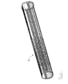
- eine Schräg-Gitteransicht eines erfindungsgemäß ausgestalteten Kranauslegers; und
- Figur 5
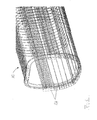
- eine vergrößerte Ansicht des vorderen Kragenbereichs des Auslegers, der in der
Figur 4 dargestellt ist. - Die in den Zeichnungen dargestellten Auslegervarianten können so gestaltet werden, wie dies weiter oben allgemein und hierin für verschiedene Ausführungsformen dargestellt wird. In den Zeichnungen weist das Bezugszeichen 10 ganz allgemein auf den Ausleger bzw. den Auslegerquerschnitt. Mit dem Bezugszeichen 11 sind vorgespannte Zugelemente bezeichnet, die sich innerhalb von Hohlprofilen 12 befinden. Das Bezugszeichen 13 zeigt auf eine Schicht aus Querfasern, während mit 14 eine Schutz- bzw. Gleitschicht bezeichnet wird. Die innere Schale 15 ist eine formgebende Schale, und die im Übergangsbereich zwischen Oberschale und vertikalem Abschnitt angeordneten Lamellen bzw. Lamellenelemente sind mit dem Bezugszeichen 16 versehen worden. Die Anordnung der Verankerungen, in denen die Sensoren und/oder Aktoren untergebracht sind, sind mit dem Bezugszeichen 17 gekennzeichnet.
Claims (13)
- Auslegerteil (10) für einen Kran, insbesondere Mobilkran, mit einer formgebenden Schale (15), Zugelementen (11) und einer Ummantelung (13, 14), dadurch gekennzeichnet, dass die Zugelemente (11) vorgespannt und mit Sensoren bestückt sind.
- Auslegerteil nach Anspruch 1, dadurch gekennzeichnet, dass die Zugelemente (11) mittels Aktoren eine veränderbare Druck-Vorspannung in das Auslegerteil einleiten.
- Auslegerteil nach einem der vorgehenden Ansprüche, dadurch gekennzeichnet, dass das Auslegerteil mittels Sensoren und Aktoren über einen Regelkreis äußeren Einwirkungen adaptiv entgegenwirkt.
- Auslegerteil nach einem der vorgehenden Ansprüche, dadurch gekennzeichnet, dass Verankerungen (17) der Zugelemente (11) in oder an den Endrahmen angeordnet sind.
- Auslegerteil nach einem der vorgehenden Ansprüche, dadurch gekennzeichnet, dass die Sensoren in den Zugelementen integriert sind.
- Auslegerteil nach einem der vorgehenden Ansprüche, dadurch gekennzeichnet, dass sich die Sensoren und/oder Aktoren an den Enden der Zugelemente (11) befinden.
- Auslegerteil nach einem der vorgehenden Ansprüche, dadurch gekennzeichnet, dass die Zugelemente (11) von einer quer zur Auslegerachse verlaufenden Faserschicht (13) ummantelt sind.
- Auslegerteil nach einem der vorgehenden Ansprüche, dadurch gekennzeichnet, dass die Zugelemente (11) in Kanälen oder Hohlprofilen (12) verlaufen.
- Auslegerteil nach einem der vorgehenden Ansprüche, dadurch gekennzeichnet, dass die Zugelemente (11) in einer elastischen Matrix eingebettet sind.
- Auslegerteil nach einem der vorgehenden Ansprüche, dadurch gekennzeichnet, dass die Zugelemente (11) umwickelt und eingeklemmt werden.
- Ausleger nach einem der vorgehenden Ansprüche, dadurch gekennzeichnet, dass die Zugelemente vorgespannt und schubfest mit der formgebenden Schale (15) und/oder mit der Umhüllung bzw. Ummantelung (13, 14), verbunden sind.
- Ausleger nach einem der vorgehenden Ansprüche, dadurch gekennzeichnet, dass die formgebende Schale, die Hohlprofile mit den Zugelementen und die Umhüllung schubfest verbunden sind und ein Sandwichprofil bilden.
- Ausleger nach einem der vorgehenden Ansprüche, dadurch gekennzeichnet, dass die Zugelemente (11) in Längsrichtung der Auslegerachse und/oder schräg dazu verlaufen.
Applications Claiming Priority (1)
| Application Number | Priority Date | Filing Date | Title |
|---|---|---|---|
| DE202010006624U DE202010006624U1 (de) | 2010-05-10 | 2010-05-10 | Kranausleger, insbesondere Mobilkranausleger, mit vorgespannten Zugelementen |
Publications (2)
| Publication Number | Publication Date |
|---|---|
| EP2386517A1 true EP2386517A1 (de) | 2011-11-16 |
| EP2386517B1 EP2386517B1 (de) | 2013-01-23 |
Family
ID=42539029
Family Applications (1)
| Application Number | Title | Priority Date | Filing Date |
|---|---|---|---|
| EP11160100A Not-in-force EP2386517B1 (de) | 2010-05-10 | 2011-03-29 | Kranausleger, insbesondere Mobilkranausleger, mit vorgespannten Zugelementen |
Country Status (9)
| Country | Link |
|---|---|
| US (1) | US8646629B2 (de) |
| EP (1) | EP2386517B1 (de) |
| JP (1) | JP5538300B2 (de) |
| KR (1) | KR20110124141A (de) |
| CN (1) | CN102241369B (de) |
| BR (1) | BRPI1102499A2 (de) |
| CA (1) | CA2736302C (de) |
| DE (1) | DE202010006624U1 (de) |
| ES (1) | ES2403704T3 (de) |
Families Citing this family (6)
| Publication number | Priority date | Publication date | Assignee | Title |
|---|---|---|---|---|
| CN102733609B (zh) * | 2012-06-26 | 2016-01-20 | 三一汽车制造有限公司 | 一种臂架、臂架系统和工程机械 |
| US9630816B1 (en) | 2013-03-11 | 2017-04-25 | Oz Lifting Products, LLC | Portable crane formed of composite members |
| ITMI20131680A1 (it) * | 2013-10-11 | 2015-04-12 | Cifa Spa | Dispositivo ausiliario per una gru e gru comprendente tale dispositivo ausiliario |
| RU175228U1 (ru) * | 2017-07-14 | 2017-11-28 | Акционерное общество "Галичский автокрановый завод" | Стрела подъёмного крана |
| US12221796B2 (en) | 2020-07-14 | 2025-02-11 | Sany Automobile Manufacturing Co., Ltd. | Boom, boom assembly and work machine |
| CN111719865A (zh) * | 2020-07-14 | 2020-09-29 | 三一汽车制造有限公司 | 臂架、臂架组件和作业机械 |
Citations (17)
| Publication number | Priority date | Publication date | Assignee | Title |
|---|---|---|---|---|
| GB1326943A (en) | 1970-08-06 | 1973-08-15 | Fischer H C | Stressed elements and production thereof |
| EP0117774A1 (de) | 1983-01-21 | 1984-09-05 | Creusot-Loire | Teleskopkranausleger |
| EP0449208A2 (de) | 1990-03-30 | 1991-10-02 | Kabushiki Kaisha Toshiba | ECL/TTL-Pegelumsetzer |
| US5238716A (en) | 1991-07-19 | 1993-08-24 | Yutaka Adachi | Composite beam having a hollow cross section |
| US5333422A (en) | 1992-12-02 | 1994-08-02 | The United States Of America As Represented By The United States Department Of Energy | Lightweight extendable and retractable pole |
| DE4408444C1 (de) | 1994-03-12 | 1995-04-06 | Dornier Gmbh | Rohr oder Hohlprofil mit besonderen Festigkeitseigenschaften bei geringem Gewicht und Verfahren zu seiner Herstellung |
| EP0668238A1 (de) | 1994-02-18 | 1995-08-23 | EC Engineering + Consulting Spezialmaschinen GmbH | Auslegerprofil |
| EP0968955A2 (de) * | 1998-07-03 | 2000-01-05 | Grove U.S. LLC | Ausleger aus Verbundwerkstoff |
| DE10022658A1 (de) | 1999-06-28 | 2001-03-15 | Mannesmann Ag | Teleskopkran |
| DE20004016U1 (de) | 2000-03-03 | 2001-07-12 | Liebherr-Werk Ehingen Gmbh, 89584 Ehingen | Teleskopausleger für Krane, vorzugsweise Fahrzeugkrane |
| DE20020974U1 (de) | 2000-12-12 | 2002-04-25 | Liebherr-Werk Ehingen Gmbh, 89584 Ehingen | Fahrzeugkran |
| US6755212B1 (en) * | 2001-02-23 | 2004-06-29 | Schwing America, Inc. | Boom stiffening system |
| EP1466855A2 (de) * | 2003-04-08 | 2004-10-13 | Grove U.S. LLC | Spannsystem für einen mobil-teleskopkran |
| EP0814050B1 (de) | 1996-06-18 | 2005-08-03 | Grove U.S. LLC | Teleskopausleger für Fahrzeugkrane |
| DE19948830B4 (de) | 1999-10-06 | 2005-11-24 | Terex-Demag Gmbh & Co. Kg | Teleskopausleger für Krane |
| DE202009009143U1 (de) | 2009-07-07 | 2009-09-03 | Terex Demag Gmbh | Teleskopausleger für Krane, insbesondere Fahrzeugkrane |
| DE102008013203A1 (de) | 2008-03-08 | 2009-09-17 | Terex-Demag Gmbh | Ausleger zur endseitigen Aufnahme von Lasten, Ausleger-Baugruppe mit mindestens zwei derartigen Auslegern sowie Verfahren zur Herstellung eines derartigen Auslegers |
Family Cites Families (7)
| Publication number | Priority date | Publication date | Assignee | Title |
|---|---|---|---|---|
| JPH0729351B2 (ja) | 1986-05-28 | 1995-04-05 | 元麿 青木 | 射出成形機における作動油冷却方法 |
| US5311510A (en) | 1991-07-30 | 1994-05-10 | The Furukawa Electric Co., Ltd. | Data storing system for a communication control circuit |
| JP3175202B2 (ja) | 1991-07-30 | 2001-06-11 | 古河電気工業株式会社 | 通信制御回路の受信データ格納方法 |
| DE4134787A1 (de) | 1991-10-22 | 1993-04-29 | Sicom Ges Fuer Sensor Und Vors | Langgestrecktes zugelement |
| DE4243878C2 (de) | 1992-12-23 | 1996-05-15 | Suspa Spannbeton Gmbh | Überwachungsvorrichtung für Bauelemente |
| JPH0891788A (ja) | 1994-09-29 | 1996-04-09 | Aichi Corp | 繊維強化プラスチック製ブーム |
| CN200995935Y (zh) * | 2006-12-28 | 2007-12-26 | 长沙中联重工科技发展股份有限公司 | 臂架用自补偿式滑块装置 |
-
2010
- 2010-05-10 DE DE202010006624U patent/DE202010006624U1/de not_active Expired - Lifetime
-
2011
- 2011-03-29 EP EP11160100A patent/EP2386517B1/de not_active Not-in-force
- 2011-03-29 ES ES11160100T patent/ES2403704T3/es active Active
- 2011-04-04 CA CA2736302A patent/CA2736302C/en not_active Expired - Fee Related
- 2011-04-20 US US13/090,974 patent/US8646629B2/en not_active Expired - Fee Related
- 2011-05-03 CN CN201110113293.0A patent/CN102241369B/zh not_active Expired - Fee Related
- 2011-05-04 KR KR1020110042209A patent/KR20110124141A/ko not_active Ceased
- 2011-05-09 JP JP2011103974A patent/JP5538300B2/ja not_active Expired - Fee Related
- 2011-05-09 BR BRPI1102499-2A patent/BRPI1102499A2/pt not_active IP Right Cessation
Patent Citations (18)
| Publication number | Priority date | Publication date | Assignee | Title |
|---|---|---|---|---|
| GB1326943A (en) | 1970-08-06 | 1973-08-15 | Fischer H C | Stressed elements and production thereof |
| EP0117774A1 (de) | 1983-01-21 | 1984-09-05 | Creusot-Loire | Teleskopkranausleger |
| EP0449208A2 (de) | 1990-03-30 | 1991-10-02 | Kabushiki Kaisha Toshiba | ECL/TTL-Pegelumsetzer |
| US5238716A (en) | 1991-07-19 | 1993-08-24 | Yutaka Adachi | Composite beam having a hollow cross section |
| US5333422A (en) | 1992-12-02 | 1994-08-02 | The United States Of America As Represented By The United States Department Of Energy | Lightweight extendable and retractable pole |
| EP0668238A1 (de) | 1994-02-18 | 1995-08-23 | EC Engineering + Consulting Spezialmaschinen GmbH | Auslegerprofil |
| DE4408444C1 (de) | 1994-03-12 | 1995-04-06 | Dornier Gmbh | Rohr oder Hohlprofil mit besonderen Festigkeitseigenschaften bei geringem Gewicht und Verfahren zu seiner Herstellung |
| EP0814050B1 (de) | 1996-06-18 | 2005-08-03 | Grove U.S. LLC | Teleskopausleger für Fahrzeugkrane |
| EP0968955B1 (de) | 1998-07-03 | 2004-02-25 | Grove U.S. LLC | Ausleger aus Verbundwerkstoff |
| EP0968955A2 (de) * | 1998-07-03 | 2000-01-05 | Grove U.S. LLC | Ausleger aus Verbundwerkstoff |
| DE10022658A1 (de) | 1999-06-28 | 2001-03-15 | Mannesmann Ag | Teleskopkran |
| DE19948830B4 (de) | 1999-10-06 | 2005-11-24 | Terex-Demag Gmbh & Co. Kg | Teleskopausleger für Krane |
| DE20004016U1 (de) | 2000-03-03 | 2001-07-12 | Liebherr-Werk Ehingen Gmbh, 89584 Ehingen | Teleskopausleger für Krane, vorzugsweise Fahrzeugkrane |
| DE20020974U1 (de) | 2000-12-12 | 2002-04-25 | Liebherr-Werk Ehingen Gmbh, 89584 Ehingen | Fahrzeugkran |
| US6755212B1 (en) * | 2001-02-23 | 2004-06-29 | Schwing America, Inc. | Boom stiffening system |
| EP1466855A2 (de) * | 2003-04-08 | 2004-10-13 | Grove U.S. LLC | Spannsystem für einen mobil-teleskopkran |
| DE102008013203A1 (de) | 2008-03-08 | 2009-09-17 | Terex-Demag Gmbh | Ausleger zur endseitigen Aufnahme von Lasten, Ausleger-Baugruppe mit mindestens zwei derartigen Auslegern sowie Verfahren zur Herstellung eines derartigen Auslegers |
| DE202009009143U1 (de) | 2009-07-07 | 2009-09-03 | Terex Demag Gmbh | Teleskopausleger für Krane, insbesondere Fahrzeugkrane |
Also Published As
| Publication number | Publication date |
|---|---|
| JP2011236055A (ja) | 2011-11-24 |
| US8646629B2 (en) | 2014-02-11 |
| EP2386517B1 (de) | 2013-01-23 |
| JP5538300B2 (ja) | 2014-07-02 |
| CN102241369A (zh) | 2011-11-16 |
| KR20110124141A (ko) | 2011-11-16 |
| CN102241369B (zh) | 2014-12-03 |
| BRPI1102499A2 (pt) | 2012-10-16 |
| US20110272378A1 (en) | 2011-11-10 |
| CA2736302A1 (en) | 2011-11-10 |
| CA2736302C (en) | 2013-08-27 |
| ES2403704T3 (es) | 2013-05-21 |
| DE202010006624U1 (de) | 2010-08-05 |
Similar Documents
| Publication | Publication Date | Title |
|---|---|---|
| EP2386517B1 (de) | Kranausleger, insbesondere Mobilkranausleger, mit vorgespannten Zugelementen | |
| EP2997197B1 (de) | Verfahren zum vorspannen eines stahl-bauwerkes, sowie damit vorgespanntes stahl-bauwerk | |
| EP2476801B1 (de) | Kombiniertes Seil aus Kunststofffasern und Stahldrahtlitzen sowie kombinierte Litze aus Kunststofffasern und Stahldrähten | |
| EP2252540B1 (de) | Ein metallisches hohlprofiel aufweisender ausleger mit verstärkungslage aus faser-kunststoff-verbund sowie sensorelement | |
| EP2361823B1 (de) | Balkenförmiges, langgestrecktes Trägerelement und Verfahren für seine Herstellung | |
| EP1924751B1 (de) | Bewehrungskörper aus faserverstärktem kunststoff | |
| DE102009040515A1 (de) | Rotorblatt für eine Windturbine mit horizontaler Rotationsachse | |
| EP2434143B1 (de) | Rotorblatt oder Rotorblattsegment für eine Windenergieanlage | |
| DE102014100814B4 (de) | Turmbauwerk für eine Windenergieanlage | |
| DE202008017465U1 (de) | Hybride textile Bewehrung von Mauerwerk, textilbewehrte Bauelemente bzw. Verstärkungsschichten für Bauelemente | |
| DE102011003602B4 (de) | Sicherungssystem für ein Rotorblatt einer Windenergieanlage, Rotorblatt und Windenergieanlage | |
| EP3883877B1 (de) | Seiltrommel für eine seilwinde sowie verfahren zu deren herstellung | |
| DE202016005619U1 (de) | Kran | |
| DE102022132028B3 (de) | Kran mit Abspannbock und Verfahren zum Abspannen eines solchen | |
| EP3612383B1 (de) | Tragwerk für einen kran und ähnliche arbeitsmaschinen, sowie kran mit einem solchen tragwerk | |
| EP3845354B1 (de) | Verfahren zum herstellen von segmenten für einen turm, vorgespanntes segment, turmring, turm und windenergieanlage | |
| EP2371756B1 (de) | Rückfallstütze | |
| DE102011079842B4 (de) | Vorrichtung mit einem Torsionsabschnitt | |
| EP2436878B1 (de) | Koppelbolzen für Turbinenschaufeln | |
| EP3307967B1 (de) | Gittermaststruktur sowie verfahren zur standfestigkeitserhöhung an eine gittermaststruktur | |
| DE102010048057B4 (de) | Laufkatze aus carbonfaserverstärktem Kunststoff | |
| EP2527232B1 (de) | Aluminiumdruckgussteil | |
| EP3408212B1 (de) | Tragstruktur für einen kran und kran hiermit | |
| EP2366654B1 (de) | Lenkung eines Portalstaplers | |
| EP3688307B1 (de) | Spannglied mit schlauchumhüllung |
Legal Events
| Date | Code | Title | Description |
|---|---|---|---|
| AK | Designated contracting states |
Kind code of ref document: A1 Designated state(s): AL AT BE BG CH CY CZ DE DK EE ES FI FR GB GR HR HU IE IS IT LI LT LU LV MC MK MT NL NO PL PT RO RS SE SI SK SM TR |
|
| AX | Request for extension of the european patent |
Extension state: BA ME |
|
| PUAI | Public reference made under article 153(3) epc to a published international application that has entered the european phase |
Free format text: ORIGINAL CODE: 0009012 |
|
| 17P | Request for examination filed |
Effective date: 20120222 |
|
| RIC1 | Information provided on ipc code assigned before grant |
Ipc: B66C 23/64 20060101AFI20120629BHEP Ipc: B66C 23/70 20060101ALI20120629BHEP |
|
| GRAP | Despatch of communication of intention to grant a patent |
Free format text: ORIGINAL CODE: EPIDOSNIGR1 |
|
| GRAS | Grant fee paid |
Free format text: ORIGINAL CODE: EPIDOSNIGR3 |
|
| GRAA | (expected) grant |
Free format text: ORIGINAL CODE: 0009210 |
|
| AK | Designated contracting states |
Kind code of ref document: B1 Designated state(s): AL AT BE BG CH CY CZ DE DK EE ES FI FR GB GR HR HU IE IS IT LI LT LU LV MC MK MT NL NO PL PT RO RS SE SI SK SM TR |
|
| REG | Reference to a national code |
Ref country code: GB Ref legal event code: FG4D Free format text: NOT ENGLISH |
|
| REG | Reference to a national code |
Ref country code: CH Ref legal event code: EP |
|
| REG | Reference to a national code |
Ref country code: AT Ref legal event code: REF Ref document number: 594843 Country of ref document: AT Kind code of ref document: T Effective date: 20130215 Ref country code: CH Ref legal event code: EP |
|
| REG | Reference to a national code |
Ref country code: IE Ref legal event code: FG4D Free format text: LANGUAGE OF EP DOCUMENT: GERMAN |
|
| REG | Reference to a national code |
Ref country code: DE Ref legal event code: R096 Ref document number: 502011000376 Country of ref document: DE Effective date: 20130321 |
|
| PGFP | Annual fee paid to national office [announced via postgrant information from national office to epo] |
Ref country code: ES Payment date: 20130326 Year of fee payment: 3 |
|
| REG | Reference to a national code |
Ref country code: ES Ref legal event code: FG2A Ref document number: 2403704 Country of ref document: ES Kind code of ref document: T3 Effective date: 20130521 |
|
| REG | Reference to a national code |
Ref country code: LT Ref legal event code: MG4D |
|
| REG | Reference to a national code |
Ref country code: NL Ref legal event code: VDEP Effective date: 20130123 |
|
| PG25 | Lapsed in a contracting state [announced via postgrant information from national office to epo] |
Ref country code: IS Free format text: LAPSE BECAUSE OF FAILURE TO SUBMIT A TRANSLATION OF THE DESCRIPTION OR TO PAY THE FEE WITHIN THE PRESCRIBED TIME-LIMIT Effective date: 20130523 Ref country code: SE Free format text: LAPSE BECAUSE OF FAILURE TO SUBMIT A TRANSLATION OF THE DESCRIPTION OR TO PAY THE FEE WITHIN THE PRESCRIBED TIME-LIMIT Effective date: 20130123 Ref country code: NO Free format text: LAPSE BECAUSE OF FAILURE TO SUBMIT A TRANSLATION OF THE DESCRIPTION OR TO PAY THE FEE WITHIN THE PRESCRIBED TIME-LIMIT Effective date: 20130423 Ref country code: LT Free format text: LAPSE BECAUSE OF FAILURE TO SUBMIT A TRANSLATION OF THE DESCRIPTION OR TO PAY THE FEE WITHIN THE PRESCRIBED TIME-LIMIT Effective date: 20130123 Ref country code: BG Free format text: LAPSE BECAUSE OF FAILURE TO SUBMIT A TRANSLATION OF THE DESCRIPTION OR TO PAY THE FEE WITHIN THE PRESCRIBED TIME-LIMIT Effective date: 20130423 |
|
| PG25 | Lapsed in a contracting state [announced via postgrant information from national office to epo] |
Ref country code: PT Free format text: LAPSE BECAUSE OF FAILURE TO SUBMIT A TRANSLATION OF THE DESCRIPTION OR TO PAY THE FEE WITHIN THE PRESCRIBED TIME-LIMIT Effective date: 20130523 Ref country code: NL Free format text: LAPSE BECAUSE OF FAILURE TO SUBMIT A TRANSLATION OF THE DESCRIPTION OR TO PAY THE FEE WITHIN THE PRESCRIBED TIME-LIMIT Effective date: 20130123 Ref country code: LV Free format text: LAPSE BECAUSE OF FAILURE TO SUBMIT A TRANSLATION OF THE DESCRIPTION OR TO PAY THE FEE WITHIN THE PRESCRIBED TIME-LIMIT Effective date: 20130123 Ref country code: PL Free format text: LAPSE BECAUSE OF FAILURE TO SUBMIT A TRANSLATION OF THE DESCRIPTION OR TO PAY THE FEE WITHIN THE PRESCRIBED TIME-LIMIT Effective date: 20130123 Ref country code: SI Free format text: LAPSE BECAUSE OF FAILURE TO SUBMIT A TRANSLATION OF THE DESCRIPTION OR TO PAY THE FEE WITHIN THE PRESCRIBED TIME-LIMIT Effective date: 20130123 Ref country code: FI Free format text: LAPSE BECAUSE OF FAILURE TO SUBMIT A TRANSLATION OF THE DESCRIPTION OR TO PAY THE FEE WITHIN THE PRESCRIBED TIME-LIMIT Effective date: 20130123 Ref country code: GR Free format text: LAPSE BECAUSE OF FAILURE TO SUBMIT A TRANSLATION OF THE DESCRIPTION OR TO PAY THE FEE WITHIN THE PRESCRIBED TIME-LIMIT Effective date: 20130424 |
|
| BERE | Be: lapsed |
Owner name: MANITOWOC CRANE GROUP FRANCE SAS Effective date: 20130331 |
|
| PG25 | Lapsed in a contracting state [announced via postgrant information from national office to epo] |
Ref country code: RS Free format text: LAPSE BECAUSE OF FAILURE TO SUBMIT A TRANSLATION OF THE DESCRIPTION OR TO PAY THE FEE WITHIN THE PRESCRIBED TIME-LIMIT Effective date: 20130123 Ref country code: HR Free format text: LAPSE BECAUSE OF FAILURE TO SUBMIT A TRANSLATION OF THE DESCRIPTION OR TO PAY THE FEE WITHIN THE PRESCRIBED TIME-LIMIT Effective date: 20130123 |
|
| PG25 | Lapsed in a contracting state [announced via postgrant information from national office to epo] |
Ref country code: DK Free format text: LAPSE BECAUSE OF FAILURE TO SUBMIT A TRANSLATION OF THE DESCRIPTION OR TO PAY THE FEE WITHIN THE PRESCRIBED TIME-LIMIT Effective date: 20130123 Ref country code: MC Free format text: LAPSE BECAUSE OF NON-PAYMENT OF DUE FEES Effective date: 20130331 Ref country code: SK Free format text: LAPSE BECAUSE OF FAILURE TO SUBMIT A TRANSLATION OF THE DESCRIPTION OR TO PAY THE FEE WITHIN THE PRESCRIBED TIME-LIMIT Effective date: 20130123 Ref country code: EE Free format text: LAPSE BECAUSE OF FAILURE TO SUBMIT A TRANSLATION OF THE DESCRIPTION OR TO PAY THE FEE WITHIN THE PRESCRIBED TIME-LIMIT Effective date: 20130123 Ref country code: CZ Free format text: LAPSE BECAUSE OF FAILURE TO SUBMIT A TRANSLATION OF THE DESCRIPTION OR TO PAY THE FEE WITHIN THE PRESCRIBED TIME-LIMIT Effective date: 20130123 Ref country code: RO Free format text: LAPSE BECAUSE OF FAILURE TO SUBMIT A TRANSLATION OF THE DESCRIPTION OR TO PAY THE FEE WITHIN THE PRESCRIBED TIME-LIMIT Effective date: 20130123 |
|
| PG25 | Lapsed in a contracting state [announced via postgrant information from national office to epo] |
Ref country code: CY Free format text: LAPSE BECAUSE OF FAILURE TO SUBMIT A TRANSLATION OF THE DESCRIPTION OR TO PAY THE FEE WITHIN THE PRESCRIBED TIME-LIMIT Effective date: 20130123 |
|
| PLBE | No opposition filed within time limit |
Free format text: ORIGINAL CODE: 0009261 |
|
| STAA | Information on the status of an ep patent application or granted ep patent |
Free format text: STATUS: NO OPPOSITION FILED WITHIN TIME LIMIT |
|
| 26N | No opposition filed |
Effective date: 20131024 |
|
| REG | Reference to a national code |
Ref country code: IE Ref legal event code: MM4A |
|
| PG25 | Lapsed in a contracting state [announced via postgrant information from national office to epo] |
Ref country code: AL Free format text: LAPSE BECAUSE OF FAILURE TO SUBMIT A TRANSLATION OF THE DESCRIPTION OR TO PAY THE FEE WITHIN THE PRESCRIBED TIME-LIMIT Effective date: 20130123 Ref country code: IE Free format text: LAPSE BECAUSE OF NON-PAYMENT OF DUE FEES Effective date: 20130329 Ref country code: BE Free format text: LAPSE BECAUSE OF NON-PAYMENT OF DUE FEES Effective date: 20130331 |
|
| REG | Reference to a national code |
Ref country code: DE Ref legal event code: R097 Ref document number: 502011000376 Country of ref document: DE Effective date: 20131024 |
|
| PGFP | Annual fee paid to national office [announced via postgrant information from national office to epo] |
Ref country code: FR Payment date: 20140319 Year of fee payment: 4 Ref country code: IT Payment date: 20140331 Year of fee payment: 4 |
|
| PG25 | Lapsed in a contracting state [announced via postgrant information from national office to epo] |
Ref country code: MT Free format text: LAPSE BECAUSE OF FAILURE TO SUBMIT A TRANSLATION OF THE DESCRIPTION OR TO PAY THE FEE WITHIN THE PRESCRIBED TIME-LIMIT Effective date: 20130123 |
|
| PGFP | Annual fee paid to national office [announced via postgrant information from national office to epo] |
Ref country code: DE Payment date: 20140328 Year of fee payment: 4 |
|
| REG | Reference to a national code |
Ref country code: CH Ref legal event code: PL |
|
| PG25 | Lapsed in a contracting state [announced via postgrant information from national office to epo] |
Ref country code: CH Free format text: LAPSE BECAUSE OF NON-PAYMENT OF DUE FEES Effective date: 20140331 Ref country code: LI Free format text: LAPSE BECAUSE OF NON-PAYMENT OF DUE FEES Effective date: 20140331 |
|
| REG | Reference to a national code |
Ref country code: DE Ref legal event code: R082 Ref document number: 502011000376 Country of ref document: DE Representative=s name: SCHWABE SANDMAIR MARX, DE |
|
| REG | Reference to a national code |
Ref country code: DE Ref legal event code: R081 Ref document number: 502011000376 Country of ref document: DE Owner name: MANITOWOC CRANE GROUP FRANCE SAS, FR Free format text: FORMER OWNER: MANITOWOC CRANE GROUP FRANCE SAS, ECULLY, FR Effective date: 20150317 Ref country code: DE Ref legal event code: R082 Ref document number: 502011000376 Country of ref document: DE Representative=s name: SCHWABE SANDMAIR MARX, DE Effective date: 20150317 |
|
| PG25 | Lapsed in a contracting state [announced via postgrant information from national office to epo] |
Ref country code: SM Free format text: LAPSE BECAUSE OF FAILURE TO SUBMIT A TRANSLATION OF THE DESCRIPTION OR TO PAY THE FEE WITHIN THE PRESCRIBED TIME-LIMIT Effective date: 20130123 |
|
| PG25 | Lapsed in a contracting state [announced via postgrant information from national office to epo] |
Ref country code: TR Free format text: LAPSE BECAUSE OF FAILURE TO SUBMIT A TRANSLATION OF THE DESCRIPTION OR TO PAY THE FEE WITHIN THE PRESCRIBED TIME-LIMIT Effective date: 20130123 |
|
| PG25 | Lapsed in a contracting state [announced via postgrant information from national office to epo] |
Ref country code: LU Free format text: LAPSE BECAUSE OF NON-PAYMENT OF DUE FEES Effective date: 20130329 Ref country code: MK Free format text: LAPSE BECAUSE OF FAILURE TO SUBMIT A TRANSLATION OF THE DESCRIPTION OR TO PAY THE FEE WITHIN THE PRESCRIBED TIME-LIMIT Effective date: 20130123 Ref country code: HU Free format text: LAPSE BECAUSE OF FAILURE TO SUBMIT A TRANSLATION OF THE DESCRIPTION OR TO PAY THE FEE WITHIN THE PRESCRIBED TIME-LIMIT; INVALID AB INITIO Effective date: 20110329 |
|
| REG | Reference to a national code |
Ref country code: DE Ref legal event code: R119 Ref document number: 502011000376 Country of ref document: DE |
|
| GBPC | Gb: european patent ceased through non-payment of renewal fee |
Effective date: 20150329 |
|
| PG25 | Lapsed in a contracting state [announced via postgrant information from national office to epo] |
Ref country code: IT Free format text: LAPSE BECAUSE OF NON-PAYMENT OF DUE FEES Effective date: 20150329 |
|
| REG | Reference to a national code |
Ref country code: FR Ref legal event code: ST Effective date: 20151130 |
|
| PG25 | Lapsed in a contracting state [announced via postgrant information from national office to epo] |
Ref country code: DE Free format text: LAPSE BECAUSE OF NON-PAYMENT OF DUE FEES Effective date: 20151001 Ref country code: GB Free format text: LAPSE BECAUSE OF NON-PAYMENT OF DUE FEES Effective date: 20150329 |
|
| PG25 | Lapsed in a contracting state [announced via postgrant information from national office to epo] |
Ref country code: FR Free format text: LAPSE BECAUSE OF NON-PAYMENT OF DUE FEES Effective date: 20150331 |
|
| REG | Reference to a national code |
Ref country code: ES Ref legal event code: FD2A Effective date: 20160426 |
|
| PG25 | Lapsed in a contracting state [announced via postgrant information from national office to epo] |
Ref country code: ES Free format text: LAPSE BECAUSE OF NON-PAYMENT OF DUE FEES Effective date: 20150330 |
|
| REG | Reference to a national code |
Ref country code: AT Ref legal event code: MM01 Ref document number: 594843 Country of ref document: AT Kind code of ref document: T Effective date: 20160329 |
|
| PG25 | Lapsed in a contracting state [announced via postgrant information from national office to epo] |
Ref country code: AT Free format text: LAPSE BECAUSE OF NON-PAYMENT OF DUE FEES Effective date: 20160329 |