EP2384403B1 - Doppelkupplung mit doppelgabelbetätigung - Google Patents
Doppelkupplung mit doppelgabelbetätigung Download PDFInfo
- Publication number
- EP2384403B1 EP2384403B1 EP10707573.1A EP10707573A EP2384403B1 EP 2384403 B1 EP2384403 B1 EP 2384403B1 EP 10707573 A EP10707573 A EP 10707573A EP 2384403 B1 EP2384403 B1 EP 2384403B1
- Authority
- EP
- European Patent Office
- Prior art keywords
- fork
- articulation
- rotation
- rotational axis
- axis
- Prior art date
- Legal status (The legal status is an assumption and is not a legal conclusion. Google has not performed a legal analysis and makes no representation as to the accuracy of the status listed.)
- Not-in-force
Links
Images


Classifications
-
- F—MECHANICAL ENGINEERING; LIGHTING; HEATING; WEAPONS; BLASTING
- F16—ENGINEERING ELEMENTS AND UNITS; GENERAL MEASURES FOR PRODUCING AND MAINTAINING EFFECTIVE FUNCTIONING OF MACHINES OR INSTALLATIONS; THERMAL INSULATION IN GENERAL
- F16D—COUPLINGS FOR TRANSMITTING ROTATION; CLUTCHES; BRAKES
- F16D23/00—Details of mechanically-actuated clutches not specific for one distinct type
- F16D23/12—Mechanical clutch-actuating mechanisms arranged outside the clutch as such
-
- F—MECHANICAL ENGINEERING; LIGHTING; HEATING; WEAPONS; BLASTING
- F16—ENGINEERING ELEMENTS AND UNITS; GENERAL MEASURES FOR PRODUCING AND MAINTAINING EFFECTIVE FUNCTIONING OF MACHINES OR INSTALLATIONS; THERMAL INSULATION IN GENERAL
- F16D—COUPLINGS FOR TRANSMITTING ROTATION; CLUTCHES; BRAKES
- F16D21/00—Systems comprising a plurality of actuated clutches
- F16D21/02—Systems comprising a plurality of actuated clutches for interconnecting three or more shafts or other transmission members in different ways
-
- F—MECHANICAL ENGINEERING; LIGHTING; HEATING; WEAPONS; BLASTING
- F16—ENGINEERING ELEMENTS AND UNITS; GENERAL MEASURES FOR PRODUCING AND MAINTAINING EFFECTIVE FUNCTIONING OF MACHINES OR INSTALLATIONS; THERMAL INSULATION IN GENERAL
- F16D—COUPLINGS FOR TRANSMITTING ROTATION; CLUTCHES; BRAKES
- F16D23/00—Details of mechanically-actuated clutches not specific for one distinct type
- F16D23/12—Mechanical clutch-actuating mechanisms arranged outside the clutch as such
- F16D23/14—Clutch-actuating sleeves or bearings; Actuating members directly connected to clutch-actuating sleeves or bearings
- F16D2023/141—Clutch-actuating sleeves or bearings; Actuating members directly connected to clutch-actuating sleeves or bearings characterised by using a fork; Details of forks
Definitions
- the present invention relates to a dual clutch mechanism having a dual fork control device.
- the present invention more particularly relates to a double clutch mechanism according to the preamble of claim 1.
- Such a dual clutch mechanism is used in particular to alternately couple the shaft of a vehicle engine with two coaxial input shafts of a gearbox, said double clutch gearbox.
- the double-clutch mechanism also known as a double clutch, makes it possible to change gears while maintaining the transmission of engine torque to the wheels of the vehicle.
- the double clutch mechanism generally comprises a first clutch and a second clutch respectively associated with even and odd gear ratios.
- the first clutch is disengaged while the second clutch is engaged so that the engine torque is transferred progressively from the first clutch to the second clutch.
- the sum of the torques transmitted by the first and second clutches is always substantially equal to the engine torque.
- the double clutch mechanism further comprises a fixed housing defining a volume in which are housed the two gearshift clutches of different ratios.
- Each clutch mechanism includes a diaphragm for cooperating with a pressure plate integral in rotation of the cover and the motor shaft.
- Each diaphragm is movable, by means of a corresponding control stop, between at least a first position and a second position.
- Each pressure plate urged by the corresponding diaphragm, is intended to grip a friction disc between this pressure plate and a corresponding reaction plate.
- each friction disk is rotatably connected to a corresponding gearbox shaft and each pressure plate is rotatably connected to a cover, generally connected to the drive shaft by connecting means such as a steering wheel. flexible or double damping flywheel.
- Such a mechanism is equipped with an associated control device mainly comprising actuating means able to selectively bias each of the first and second forks intended to actuate between two extreme positions of the first and second control stops respectively controlling the displacement of each of the diaphragms of the first and second clutches.
- the ranges of the control device are articulated each around a ball joint respectively fixed to the casing of the mechanism and arranged radially closer to each other, that is to say arranged l one below the other in a vertical orientation, conventionally defined as orthogonal to the longitudinal orientation which is determined by the above-mentioned X axis of rotation of the mechanism, which is also the main axis of the control stops driven by the forks.
- the figures 7 and 8 illustrate an example of a control device for a double clutch mechanism comprising two forks respectively forming levers of the first kind and which are arranged on either side of the axis of rotation.
- FIGS 9 to 11 illustrate another example of a control device for a double-clutch mechanism comprising two forks respectively forming levers of the first kind and which are arranged on the same side of the axis of rotation and longitudinally juxtaposed, that is to say arranged side by side side by side of the means of articulation.
- the arrangement of the hinge means is sometimes difficult, in particular because of implantation constraints, only a reduced space being available to accommodate the actuating means, the forks and the associated hinge means.
- the forks must be able to actuate the control stops with a sufficient stroke to satisfactorily perform the clutch or disengagement operations for each of the clutches of the mechanism .
- the invention is intended in particular to improve the control device of a double clutch while maintaining for each a simple structure, a particularly small footprint and efficient operation.
- the subject of the invention is a double clutch mechanism of the type described above, characterized in that the first fork is housed inside the second fork, said first and second concentric forks are nested one inside the other and are, in the rest position, globally coplanar.
- the implantation of the forks and the associated hinge means can be achieved in a smaller overall space, both radially than in the longitudinal direction.
- said axes of rotation of the forks are located on the same side of the X axis.
- the rotation axes of the forks are arranged so that, relative to a reference horizontal plane passing through the longitudinal axis X of rotation of the mechanism, the first axis of rotation and the second axis of rotation are of the same side of the reference plane thus defined, that is to say in the vertical direction orthogonal to said plane, either above or below.
- the arrangement of the hinge means of the forks has a smaller footprint in the radial direction and in the longitudinal direction or, with congestion radial equivalent, an upper lever length for at least one of the forks.
- the implantation of the hinge means associated with the forks is also simplified by the use of a hinge piece common to the forks.
- the common hinge part is connected to the housing of the mechanism from the front radial face or bottom of which the piece extends axially or longitudinally forwards through a foot having a predetermined length.
- control device comprising the forks whose axis of rotation, preferably a common pivot axis, carried by such a common part is likely to be disposed axially further forward with respect to the face of the casing so that the stroke performed by the thrust actuated by the fork is maximum and obtained for a corresponding stroke of the actuating means is minimal.
- each of the first and second forks is completely independent and the forks may be selectively displaced by actuating means, without any interaction between one and the other of said ranges, the forces applied to one being in particular not transmitted to the other and vice versa.
- the hinge means of the first fork and the second fork are, in a non-limiting manner, respectively constituted by a pivot and / or a ball joint.
- the invention further relates to a control device for a double clutch mechanism according to claim 12.
- the articulation surface of the first fork is intended to cooperate with at least one inner articulation surface complementary to the first articulation means and the first and second articulation surfaces of the second fork are intended to cooperate respectively with a first hinge surface and a second hinge surface complementary to the second hinge means.
- the terms “upper” and “lower” correspond respectively to the top and the bottom of the figure 1 and are determined according to the vertical orientation of the trihedron (L, V, T) and the terms “external” and “internal” are determined according to the transverse orientation of the trihedron (L, V, T), which vertical and transverse orientations are orthogonal to the aforementioned longitudinal axis X.
- an "axial" axial direction is also determined along the longitudinal axis X and a "radial” direction which, orthogonal to said axial direction, designates elements extending overall in a vertical plane (V, T) of transverse orientation.
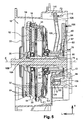
- an exemplary embodiment of a double-clutch mechanism which, in particular for equipping a motor vehicle, is designated by the general reference 10 and has an axis X of rotation, here of longitudinal orientation according to the trihedron (L, V, T).
- the double clutch mechanism 10 comprises an associated control device 12 comprising at least a double fork, more particularly illustrated in detail in FIGS. figures 2 and 3 according to a preferred embodiment of the invention.
- the double clutch mechanism 10 is housed, with at least a part of the control device 12, inside a volume delimited by a housing 14.
- the two driven shafts 16A and 16B of the mechanism 10 are concentric and are rotatably mounted coaxially with the drive shaft, the first driven shaft 16A forms a tube inside which the second driven shaft 16B is arranged.
- a free front end portion of the second driven shaft 16B extends longitudinally beyond the forward end of the first driven shaft 16A, each of said driven shafts 16A and 16B being rotatable independently of each other.
- the driven shafts 16A and 16B are intended to be connected to a gearbox (not shown) arranged longitudinally at the rear, that is to say on the right of the figure 1 beyond the fixed housing 14.
- first driven shaft 16A corresponds to certain gear ratios of the gearbox, for example the even gear ratios
- second driven shaft 16B corresponds to the other gear ratios, e.g. odd gear ratios.
- the double clutch mechanism 10 comprises a first clutch E1 and a second clutch E2 for temporarily coupling one of the driven shafts 16A, 16B to the drive shaft and which are selectively controlled by the control device 12 so as to respectively allow the passage of gear ratios of different parities.
- the mechanism 10 comprises a circular radial reaction plate 18 which is rotatably mounted about the longitudinal axis X of rotation, via a bearing, preferably constituted by a ball bearing 20.
- the reaction plate 18 is integral in rotation with the motor shaft.
- the mechanism 10 comprises connecting means 22 with the motor shaft, said means 22 being arranged at a longitudinal end front of the mechanism 10 and able to be fixed coaxially to the motor shaft.
- such connecting means are for example constituted by a flexible circular radial disk 22.
- the connecting means 22 also provide a damping and / or filtration function and are for example constituted by a double damping flywheel .
- the first clutch E1 of the mechanism 10 forms first temporary coupling means of the first driven shaft 16A with the motor shaft.
- the first clutch E1 comprises a first annular pressure plate 24 which is mounted to rotate with the reaction plate 18 about the axis X of rotation.
- the first pressure plate 24 is more particularly arranged axially vis-à-vis a rear face 26 of the reaction plate 18.
- the first pressure plate 24 is mounted to slide axially relative to the reaction plate 18.
- the first pressure plate 24 is mounted to slide axially on axial columns 28 which are fixed to the periphery of the reaction plate 18.
- the first clutch E1 comprises a first coaxial friction disk 30 which is interposed axially between the reaction plate 18 and the first pressure plate 24.
- the first friction disk 30 has on both its faces an annular friction lining 32 which is arranged axially vis-à-vis the first pressure plate 24 and the reaction plate 18.
- the first friction disc 30 is rotatably mounted to the first driven shaft 16A, and is axially slidably mounted on the first tubular driven shaft 16A between a tight front position ( figure 4 ) against the rear face 26 of the reaction plate 18 and a free rear position ( figure 1 to which it is resiliently biased and in which the first friction disc 30 is moved away from the rear face 26 of the reaction plate 18.
- the first diaphragm 34 has a radially outer ring 35 and elastic fingers 36 extending radially towards the axis X of rotation from the ring 35 to a free inner end 38. All the fingers 36 of the first diaphragm 34 are preferably identical.
- the first rear cover 40 more particularly comprises an annular radial bottom 42 and a cylindrical axial skirt 44 extending forwardly from the outer periphery of the bottom 42 to the peripheral portion of the reaction plate 18, surrounding the first pressure plate 24.
- the ring 35 of the first diaphragm 34 is for example fixed on a front face of the bottom 42 of the first cover 40 by means of a flange 47 having tabs which extend radially inwards.
- the flange 47 is fixed to the first cover 40 by rivets 48 so that the ring 35 of the first diaphragm 34 is axially clamped against the bottom 42 of the first cover 40 by the radial tabs of the flange 47.
- each finger 36 of the first diaphragm 34 is axially supported on an annular portion 50 of the first pressure plate 24.
- the fingers 36 of the first diaphragm 34 thus function in the manner of a lever which is supported by its end upper against the first fixed cover 40.
- the fingers 36 of the first diaphragm 34 are elastically flexible, in particular the free end 38 of the fingers 36 which is displaced between an extreme forward clutch position shown in FIG. figure 4 and an extreme rear declutching position shown in FIG. figure 1 or 5 .
- the first diaphragm 34 axially urges the first pressure plate 24 to clamp the first friction disk 30 against the reaction plate 18.
- the first pressure plate 24 In the extreme rear declutching position towards which the fingers 36 are resiliently biased, the first pressure plate 24 is no longer biased axially by the first diaphragm 34 so that the first friction disc 30 is then in its free rear position, as represented at figure 1 or 5 .
- the second clutch E2 comprises a second pressure plate 52 and a second friction disk 54 whose functions are respectively similar to those of the first pressure plate 24 and the first friction disk 30.
- the second pressure plate 52 is mounted axially vis-à-vis the front face 56 of the reaction plate 18.
- the second pressure plate 52 is rotationally integral with the reaction plate 18 via a second cover 58 which has a rear radial annular bottom 60 and a cylindrical axial skirt 62 which extends forward to second pressure plate 52 surrounding the first cover 40. More particularly, the second cover 58 is connected to the periphery of the second pressure plate 52.
- the second cover 58 is thus integral with the second pressure plate 52 in rotation and in axial sliding.
- the second coaxial friction disc 54 is interposed axially between the reaction plate 18 and the second pressure plate 52. It also comprises on its two faces an annular friction lining 64 which is interposed axially between the front face 56 of the reaction plate. 18 and the second pressure plate 52.
- the second friction disc 54 is intended to be clamped against the front face 56 of the reaction plate 18 by the second pressure plate 52 to temporarily couple the second driven shaft 16B with the motor shaft.
- the second friction disc 54 is rotatably mounted to the second driven shaft 16B, and is axially slidably mounted on the front end portion of the second driven shaft 16B between a rear position clamped against the front face 56 of the reaction plate 18 and a free front position to which it is resiliently biased and wherein the second friction disc 54 is remote from the front face 56 of the reaction plate 18.
- the very low axial clearance existing, in the free rear position, between the second friction disk 54 and the front face 56 of the reaction plate 18 has not been represented at the figure 1 .
- the second clutch E2 comprises a second rear axial annular diaphragm 66 for actuating the second pressure plate 52.
- the second diaphragm 66 has a structure similar to that of the first diaphragm 34.
- the second diaphragm 66 is arranged axially behind the first diaphragm 34. It is interposed axially between the edge 46 of the first cover 40 and a front face of the bottom 60 of the second cover 58. More particularly, the ring 67 of the second diaphragm 66 is arranged in axial support against a front face of the bottom 60 of the second cover 58.
- the second diaphragm 66 is for example held in position by rivets (not shown) which are fixed to the first cover 40.
- the rivets are then arranged between two consecutive fingers 68 of the second diaphragm 66 with an axial play.
- the second diaphragm 66 is held in position while allowing the fingers 68 to bend.
- the fingers 68 of the second diaphragm 66 operate in the manner of a lever.
- an axial actuation force which is applied forward to the free end 70 of the fingers 68 is transmitted to the cover 34, the fingers 68 bearing on the edge 46 of the first cover 34, then to the central plate 18 .
- the fingers 68 of the second diaphragm 66 are elastically flexible between an extreme forward clutch position which is shown in FIG. figure 5 and wherein the second diaphragm 66 axially biases rearwardly the second pressure plate 52 to clamp the first friction disk 54 against the reaction plate 18 via the second cover 58, and a rearward disengaging extreme position towards which the fingers 68 are elastically biased and wherein the second pressure plate 52 is no longer biased axially so that the second friction disk 54 is in its free forward position, as shown in FIG. figure 1 .
- the mechanism 10 further comprises the associated control device 12 which is intended to independently control, on the one hand, the first diaphragm 34 of the first clutch E1 between the extreme positions before clutch and disengagement rear and secondly the second diaphragm 66 of the second clutch E2 between the extreme front positions of clutch and rear clutch.
- control device 12 comprises a first annular stop 72 for actuating the first diaphragm 34 which is slidably mounted axially between an extreme forward clutch position, as illustrated in FIG. figure 4 , in which the stop 72 axially urges forward the free end 38 of the fingers 36 of the first diaphragm 34 in their extreme forward clutch position and an extreme rear declutching position, as illustrated in FIG. figure 1 or 5 .
- the control device 12 also comprises a second annular abutment 74 for actuating the second diaphragm 66 which is slidably mounted axially between an extreme front clutch position in which the abutment 74 axially biases forward the free end 70 of the fingers 68 of the second diaphragm 66 in their extreme forward clutch position, as illustrated in FIG. figure 5 , and an extreme rear declutching position, as illustrated in FIG. figure 1 or 4 .
- the first and second stops 72, 74 for actuation are respectively fixed on a first and a second sleeve 76, 78 axial sliding.
- the sleeves 76, 78 are slidably mounted on a tubular guide 80 having, in axial section, generally an "L" shape.
- the sleeves 76, 78 are mounted on a tubular axial portion of the guide 80 which extends forwardly from another radial portion forming a fixing flange extending radially outwardly.
- the guide 80 is fixed via the portion forming the radial flange to a front face 82 of the casing 14, for example by rivets 81.
- the first sleeve 76 is slidably mounted inside the tubular guide 80 against an inner cylindrical face 84 of the guide 80, while the second sleeve 78 is slidably mounted outside the tubular guide 80 on an outer cylindrical face 86 of the guide 80.
- the first sleeve 76 is slidably mounted around the tubular guide 80 against the outer cylindrical face 86 of the guide 80 and the second sleeve 78 is mounted around the first sleeve 76 so that the second sleeve 78 slides axially on the face outer cylindrical first sleeve 76.
- the first sleeve 76 is then interposed radially between the guide 80 and the second sleeve 78.
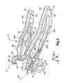
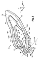
- Each stop 72, 74 can be slidably controlled by means of an associated fork, respectively a first fork 88 and a second fork 90, which are of generally radial orientation.
- the first fork 88 comprises a body 92 of generally oval shape and which comprises respectively, from the outside towards the inside in the radial direction, a portion operating member 94, an actuating portion 96 and a hinge portion 98.
- the operating portion 94 of the first fork 88 is intended to cooperate with first actuating means 100 able to exert selectively on said portion 94 a determined actuating force F1 capable of causing the displacement of the first fork 88 from a position back rest ( figure 1 ) to a position before work ( figure 4 ) corresponding to the extreme forward clutch position of the control stop 72 and the first diaphragm 34 of the first clutch E1.
- the body 92 of the first fork 88 then divides into two branches 92A, 92B each comprising a bulge which forms the actuating portion 96 intended to cooperate with the first sleeve 76 for controlling the sliding of the first stop 72 on the guide 80 .
- the two branches 92A and 92B transversely delimit, with the actuating part 94 and with the articulation part 98 arranged at each vertical end of said branches 92A, 92B of the first fork 88, a central opening 102 intended to be traversed longitudinally by the means for actuating the stops 72, 74, in particular the sleeves 76, 78 and the guide 80.
- the branches 92A, 92B of the body 92 then join to form the hinge portion 98 of the first fork 88.
- the hinge portion 98 comprises a hinge surface 104, here formed in the rear vertical face of the portion 298, which is intended to cooperate with first hinge means 106 of the first fork 88 mounted movably around a first axis of rotation 01.
- the first articulation means 106 comprise at least one so-called internal articulation surface S which is complementary to the articulation surface 104 carried by the articulation portion 98 of the first fork 88.
- the second fork 90 comprises a body 108 which, also of generally oval shape, respectively comprises, from the outside towards the inside in the radial direction, an operating part 110, an actuating part 112 and an articulation part. 114.
- the operating portion 110 of the second fork 90 is intended to cooperate with second actuating means 116 capable of exerting selectively on said portion 110 an actuating force F2 determined to cause the displacement of the second fork 90 from a position back rest ( figure 1 ) to a position before work ( figure 5 ) corresponding to the extreme front position clutch of the control stop 74 and the second diaphragm 66 of the second clutch E2.
- the body 108 of the second fork 90 then divides into two branches 108A, 108B each having a flat part which forms the actuating portion 112 intended to cooperate with the second sleeve 78 for controlling the sliding of the second stop 74 on the guide 80 .
- the two branches 108A and 108B delimit transversely with the actuating portion 112 and the hinge portion 114 at each vertical end of the second fork 90, a central opening 118 for to be traversed longitudinally by the actuating means of the stops 72, 74, in particular the sleeves 76, 78 and the guide 80.
- the central opening 118 of the second fork 90 determines an internal space inside which is arranged, globally concentrically, the first fork 88.
- Each arm 114A, 114B comprises on a rear radial face a hinge surface, respectively 120A and 120B, intended to cooperate with second hinge means of the second fork 90 which is mounted to move about a second axis of rotation 02 .
- the two arms 114A and 114B of the hinge portion 114 of the second fork 90 are generally parallel and delimit between them a housing in which the hinge portion 98, 298 of the first fork 88 penetrates so that the parts
- the hinges 98 and 114 of the forks are substantially nested one inside the other.
- first fork 88 and the second fork 90 are shaped to operate without interaction with each other so that, when moving around the second hinge means 122 associated, the second fork 90 does not enter into operation. contact with the first fork 88 and vice versa.
- the second articulation means 122 respectively comprise a first articulation surface S1 complementary to the hinge surface 120A of the arm 114A of the second fork 90 and a second hinge surface S2 complementary to the hinge surface 120B of the arm 114B of the second fork 90, said articulation surfaces S1 and S2 of the second hinge means 122 are said to be external in comparison with the internal hinge surface S of the first fork 88.
- the inner articulation surface S of the first fork 88 is arranged between said first and second outer articulation surfaces S1 and S2 of the second fork 90.
- the inner surface S is thus arranged transversely between the outer surfaces S1 and S2, said articulation surfaces S, S1 and S2 are juxtaposed next to each other so as to obtain a particularly compact and compact arrangement and this in all the orientations of the trihedron (L, V, T).
- the hinge portions 98 and 114 of the first and second forks 88 and 90 interpenetrate so that the hinge portion 98 is generally transverse between the arms 114A and 114B.
- Each of the forks 88, 90 constitutes a said lever of the second kind, that is to say by definition a lever in which the resistant force is exerted between the axis of rotation and the driving force, for example remember that a nutcracker is such a lever of the second kind.
- the rear rest position of the first fork 88 and the second fork 90 is determined by stop means (not shown) which are for example carried by the front face 82 of the casing 14 adjacent.
- the mechanism 10 advantageously comprises stop means able to limit the displacement of the forks 88, 90 and / or control stops 72, 74 axially forwardly, beyond a determined position, which is likely to occur after significant wear of the linings of each of the friction discs 30 and 54.
- the first fork 88 is movably mounted on the first articulation means 106 and around a first axis 01 while the second fork 90 is movably mounted on the second articulation means 122 and around a second axis 02.
- first hinge means 106 carrying the inner hinge surface S are aligned longitudinally with the second hinge means 122 carrying the hinge outer surfaces S1 and S2 so that the spacing of the first axis of rotation O1 of the first fork 88 is equal to the center distance of the second axis of rotation 02 of the second fork 90, the center distance referenced "e" on the figure 1 corresponding to the radial distance of each of the axes 01, 02 relative to the longitudinal axis X of rotation.
- the implantation of the forks 88 and 90 can be performed in a smaller overall size than before, especially with a smaller footprint in the radial direction compared to the state of the art.
- the axes of rotation O1 and O2 of the forks are located on the same side of the longitudinal axis X of rotation, whereby the first and second forks 88 and 90 extend on the same side of the axis X with an arm optimal leverage.
- the actuating means 100 and 116 respectively associated with the forks 88 and 90 are situated on the same side of the longitudinal axis X of rotation.
- control device 12 particularly compact and without sacrificing the performance of said device in general and forks 88 and 90 in particular.
- the points of intersection of the axes of rotation 01, 02 and a reference plane of vertical orientation passing through said longitudinal axis X of rotation are located in the same vertical half-plane.
- first and second forks 88 and 90 extend radially in the same plane and are, in rest position, globally coplanar.
- first and second forks 88 and 90 are concentric, the first fork 88 being housed inside the second fork 90.
- the first axis of rotation 01 and the second axis of rotation O2 are more particularly represented in FIG. figure 2 .
- the first and second forks 88, 90 thus have a common axis of rotation O which is therefore the only axis of rotation shown in some of the figures since, carried by the articulation means, the common axis O constitutes the axis of rotation 01 and the axis of rotation 02 respectively.
- the first articulation means 106 are constituted by a first pivot 106 so that the first axis of rotation 01 of the first fork 88, advantageously formed by the common axis O, is a pivot axis which, substantially transverse orientation, is orthogonal to the longitudinal axis of rotation X.
- the second hinge means 122 are constituted by a second pivot 122 so that the second axis of rotation 02 of the second fork 90, also formed by the common axis O, is a pivot axis which, d ' substantially transverse orientation, is orthogonal to the longitudinal axis X of rotation.
- the first fork 88 as the second fork 90 are mounted movably, between their respective rear positions of rest and before work, respectively about a first pivot axis 01 worn. by the first hinge 106 and a second pivot axis 02 carried by the second hinge means 122.
- the axes O1 and O2 of pivoting are therefore constituted by a single single common axis O of pivoting which is advantageously carried by a single hinge means forming both the first hinge means 106 of the first fork 88 and the second means hinge 122 of the second fork 90.
- first hinge means 106 of the first fork 88 and the second hinge means 122 of the second fork 90 are distinct and consist of at least two pivots arranged transversely next to each other to present the same pivot axis O.
- the respective hinge means 106, 122 of said first and second forks 88, 90 are thus advantageously made in one piece which is preferably linked to the casing 14 so that said piece forms a common hinge means for the first and second forks 88, 90.
- said piece forming a common pivot of the first and second forks 88, 90 comprises a single hinge surface 124 forming respectively the inner hinge surface S and the first and second outer hinge surfaces S1 and S2, said surface 124 thus being complementary to the respective hinge surfaces 104 and 120A, 120B of the hinge parts 98 and 114 of the first and second forks 88, 90.
- the common pivot 106-122 comprises axially at the front a head 123 bearing said single hinge surface 124 of the forks 88, 90 and, axially behind said head 123, a foot 125 which extends axially up to the face 82 of the casing 14.
- the foot 125 of the common pivot 106-122 is integral with the casing 14 and the pivot is made integrally, in one piece, with the casing 14.
- the common pivot 106-122 is a separate part which is attached to the face 82 of the casing by any appropriate means, for example by welding.
- the respective hinge surfaces 104 and 120A, 120B of the first and second forks 88, 90 on the one hand, and the single hinge surface 124 of the common pivot on the other hand, are intended to cooperate together to form a pivoting joint around the common axis O and said surfaces are constituted by cylindrical surfaces, here of generally circular section.
- the common pivot 106-122 forming the hinge means of the forks 88 and 90 is connected to the casing 14 by means of its foot 125 which extends axially forwardly, here rectilinearly, from the face 82 forming the bottom of the housing 14 of the mechanism 10.
- the common axis O of pivoting of the forks 88 and 90 is carried by the common pivot 106-122, which common pivot is likely to be, compared with the state of the art, arranged axially further forward by relative to the face 82 of the casing 14.
- each control stop 72, 74 actuated by the associated fork 88, 90 is maximum and obtained for a corresponding stroke of the actuating means 100 and 116 which is advantageously minimal.
- the arms 114A and 114B are interconnected by a portion of the body 108 which forms a bridge extending transversely between them so as to facilitate the machining of each of the surfaces 120A and 120B.
- the second fork 90 thus has an overall rigidity, in particular in its hinge portion 114, able also to avoid any contact with the first fork 88 which is arranged inside its body 108 and whose part d articulation 98 is interposed transversely between the arms 114A and 114B.
- the articulation surfaces 104, 120A and 120B of the forks 88 and 90 are machined simultaneously in a single operation for a greater precision with respect to the single hinge surface 124 complementary to the common pivot 106-122.
- figures 4 and 5 respectively illustrate the actuation of the first fork 88 and the second fork 90 by associated actuating means 100 and 116.
- the actuating means 100 and 116 consist, for example, of an actuator comprising an actuating rod whose front free end is in contact with a rear radial face, respectively 126 and 128, which each of the actuating portions 94 comprises. and 110 of the first and second forks 88, 90.
- the first actuating means 100 are controlled to apply on the rear vertical face 126 of the first fork 88 a determined force F1 which causes the pivoting of the fork 88 around the common axis of pivoting O so as to move the first fork 88 axially forward from its rear rest position, illustrated in FIG. figure 1 , to his position before work illustrated in the figure 4 .
- the displacement of the first fork 88 from its rear rest position to its front working position simultaneously causes, via the first sleeve 76 which slides on the guide 80, the displacement of the first control stop 72 from its extreme position. rear of clutch to its extreme position before clutch.
- the first control stop 72 itself acts simultaneously on the fingers 36 of the first diaphragm 36, which then urges the first pressure plate 24 towards the reaction plate 18 in order to clamp the first friction disk 30 between them to ensure the coupling the first driven shaft 16A with the motor shaft.
- the second actuating means 116 are controlled to apply on the rear vertical face 128 of the second fork 90 a determined force F2 which causes the fork 90 to pivot about the common axis of pivoting O so as to move the second fork 90 axially forward from its rearward rest position, illustrated in FIG. figure 1 , to his position before work illustrated in the figure 5 .
- the displacement of the second fork 90 from its rear rest position to its front working position simultaneously causes, via the second sleeve 78 which slides on the guide 80, the displacement of the second control stop 74 from its extreme position. rear of clutch to its extreme position before clutch.
- the second control stop 74 itself acts simultaneously on the fingers 68 of the second diaphragm 66 which then urges the second pressure plate 24, axially towards the rear, in the direction of the reaction plate 18 to clamp between them the second friction disc 54 to ensure the coupling of the second driven shaft 16B with the motor shaft.
- hinge means 106, 122 of the ranges can be envisaged without departing from the scope of the invention.
- the internal articulation surface S carried by the first articulation means 106 and associated with the first fork 88 is arranged transversely between the external articulation surfaces S1 and S2.
- the first and second articulation means 106 and 122 of the forks 88 and 90 are made as previously in the form of pivots.
- the first articulation means 106 are thus constituted by at least one so-called internal pivot, so that the first axis of rotation 01 of the first fork 88 is a pivot axis which is substantially transverse in orientation and therefore orthogonal to the longitudinal X axis of rotation.
- the second hinge means 122 are therefore also constituted by pivots, respectively a first pivot 122A and a second pivot 122B.
- the second axis of rotation 02 of the second fork 90 is a pivot axis which, determined by said pivots 122A, 122B, extends in a substantially transverse orientation and orthogonal to the longitudinal axis X of rotation.
- the first articulation means 106 formed here by the internal pivot, comprise an internal surface S for the articulation of the first fork 88, said inner surface S being intended to cooperate with the complementary hinge surface 104 that the part comprises. articulation 98 of the first fork 88.
- the first and second pivots 122A and 122B forming the second articulation means 122 respectively comprise a first external articulation surface S1 and a second external articulation surface S2 which are intended to cooperate with the complementary articulation surfaces 120A and 120B arms 114A and 114B of the hinge portion 114 of the second fork 90.
- the internal articulating surface S is arranged transversely between said first and second external articulation surfaces S1 and S2.
- first articulation means 106 carrying the internal hinge surface S are also longitudinally aligned with the second hinge means 122 carrying the hinge outer surfaces S1 and S2.
- the spacing of the first axis of rotation 01 of the first fork 88 is equal to the spacing between the second axis of rotation 02 of the second fork 90.
- the first and second forks 88, 90 thus have axes of rotation 01 and 02 which, while having the same spacing "e" with respect to the axis X, are parallel and not merged as before.
- the first axis of rotation 01 of the first fork 88 and the second axis of rotation 02 of the second fork 90 are offset longitudinally relative to each other so that the first and second forks 88 and 90 have axes of rotation which are parallel.
- the axes of rotation 01 and 02 are thus included in the same horizontal plane (L, T) according to the trihedron (L, V, T) represented in FIG. figure 7 .
- pivots 106, 122A and 122B forming my respective articulation means of said first and second forks 88 and 90 are made in one piece.
- said piece comprises a head 123 which is machined to form the hinge surfaces S, S1 and S2 of each of the pivots 106, 122A and 122B so that said head 123 no longer has a single hinge surface.
- 124 but a stepped profile comprising different sections and in which the inner surface S is arranged transversely between the external surfaces S1 and S2 and longitudinally recessed rearwardly with respect to said surfaces S1, S2.
- the common part carrying the pivots 106, 122A and 122B comprises a stepped articulation surface 124 comprising, on the one hand, at each of its transverse ends, a hinge surface section formed by the first and second surfaces S1 and S2 complementary articulation surfaces 120A and 120B arms 114A and 144B of the second fork 90 and, secondly, a central portion of hinge surface formed by the inner surface S complementary to the hinge surface 104 of the first fork 88.
- the central portion of hinge surface of the first fork 88 is interposed transversely between the sections of hinge surfaces of the second fork 90 arranged at the ends and carried by the pivots 122A and 122B integral with the common part .
- the internal articulation surface S of the first fork 88 carried by the pivot pin 106 is offset longitudinally or axially rearward with respect to the external articulation surfaces S1 and S2 of the second fork 90 carried by the pivots 122A and 122B so that the axes of rotation O1 and O2 are parallel and not merged.
- the internal articulating surface S of the first fork 88 carried by the pivot 106 is offset longitudinally forwards relative to the external articulation surfaces S1 and S2 of the second fork 90 carried by the pivots 122A and 122B so that said inner surface S protrudes axially forward with respect to said outer surfaces S1 and S2 recessed.
- said common part forms a common articulation means for the first and second forks 88 and 90 and the head 123 is extended longitudinally by a foot 125 which is connected to the face 82 of the housing 14 of the mechanism 10.
- FIG. figure 8 a second variant embodiment illustrated in FIG. figure 8 .
- the hinge means 106 and 122 pivot are similar to those described for the first variant illustrated in the figure 7 .
- the internal articulation surface S of the first fork 88 carried by the pivot 106 is not only offset longitudinally with respect to the external articulation surfaces S1 and S2 carried respectively by the pivots 122A and 122B but is further off-set. vertically so that the axes of rotation 01 and 02 are parallel but not included in a horizontal plane parallel to the longitudinal axis X of rotation.
- the invention further proposes a control device 12 for a mechanism 10 with a double clutch.
- the control device 12 comprises at least the first fork 88 and the second fork 90 arranged in an operating position in which the forks 88, 90 are associated for the control of said clutch 10.
- the articulation surface 104 of the first fork 88 is intended to cooperate with at least one internal articulation surface S complementary to the first articulation means 106.
- the first and second hinge surfaces 120A and 120B of the second fork 90 are intended to cooperate respectively with a first hinge surface S1 and a second hinge surface S2 complementary to the second hinge means 122.
- hinge means 106, 122 of the first and second forks 88 and 90 are not limited to a hinge-type pivoting.
- the first hinge means 106 of the first fork 88 and the second hinge means 122 of the second fork 90 are constituted by a ball joint.
- first hinge means 106 are constituted by at least one central ball 206 and the second hinge means 122 are constituted by at least first and second ball joints, respectively 222A and 222B.
- the first fork 88 is thus rotatably mounted about a center of rotation C whose intersection with a transverse reference half-plane, of vertical orientation and orthogonal to the longitudinal axis of rotation X, determines said first axis of rotation O1 of the first fork 88.
- the second fork 90 is rotatably mounted by means of its arm 114A around a first center of rotation C1 of a first ball 222A and through its other arm 114B around a second center of rotation. C2 of a second ball 222B.
- the centers of rotation C1 and C2 determine the second axis of rotation 02 of the second fork 90 by intersection with the reference transverse half-plane which is of vertical orientation and orthogonal to the longitudinal axis of rotation X.
- the centers of rotation C, C1 and C2 of the ball joints 206, 222A and 222B are aligned in the transverse orientation so that the first axis of rotation 01 of the first fork 88 passing through the center C is coaxial with the second axis of rotation 02 the second fork 90 passing through the centers C1 and C2.
- the axes of rotation 01, 02 are merged and the first and second forks 88, 90 have a common axis of rotation O.
- the first hinge means 106 formed by the central ball 206 comprise at least one internal articulation surface S of the first fork 88 and the second hinge means 122 are formed by the external hinges 222A and 222B which comprise respectively a first articulation surface S1 and a second articulation surface S2 of the second fork 90.
- the internal hinge surface S of the first fork 88 is arranged transversely between said first and second external articulation surfaces S1 and S2 of the second fork 90.
- the ball 206 forming the first articulation means 106 and carrying the internal articulation surface S is aligned longitudinally with the external ball joints 222A and 222B forming the second articulation means 122 and carrying the external articulation surfaces S1, S2.
- the spacing of the first axis 01 of rotation of the first fork 88 is equal to the spacing between the second axis of rotation 02 of the second fork 90.
- the ball joints 206, 222A and 222B forming the hinge means 106, 122 of the first and second forks 88 and 90 are carried by a single common piece comprising, at its forward longitudinal end, a head 123 carrying said means of articulation.
- articulation 106, 122 and a foot 125 which, extending longitudinally behind the head 123, is connected to the face 82 of the casing 14 of the mechanism.
- the figure 10 represents an alternative embodiment which is described hereinafter by comparison with the embodiment of the figure 9 .
- first hinge means 106 carrying the internal articulating surface S are offset vertically relative to the second hinge means 122 carrying the external hinge surfaces S1 and S2 so that, with respect to the longitudinal axis of rotation, the distance between the first axis 01 of rotation of the first fork 88 is different from the center distance of the second axis of rotation 02 of the second fork 90.
- first axis of rotation 01 of the first fork 88 and the second axis of rotation 02 of the second fork 90 are also offset longitudinally with respect to each other, combination or not with the fact of being offset vertically relative to each other, so that the first and second forks 88 and 90 have parallel axes of rotation 01 and 02 which are included or not in the same plane horizontal (L, T) depending on whether the means 106, 122 are only offset longitudinally or also vertically offset.
- the first and second forks 88, 90 constitute, as before, each a lever of a second type, that is each fork 88, 90 constitutes a lever in which the resisting force is opposed to it, in particular by the associated stop 72, 74 , is exerted on an actuating portion 96, 112 of the fork 88, 90 which is located between the axis of rotation 01, 02 and an operating portion 94, 110 on which actuating means 100, 116 exercise a driving force.
- the second fork 90 comprises an annular body 108 substantially of oval shape which circumferentially delimits an internal space 118 inside which is arranged, generally concentrically, the first fork 88, only the hinge parts 98 and 114 of the forks 88 , 90 being modified according to the type of articulation means 106, 122 associated.
- the embodiments of the invention are also not limited to a juxtaposition of articulation means 106, 122 which are of the same type, that is to say either to pivot as illustrated in Figures 6 to 8 either with a ball joint as shown in figures 9 and 10 these types of articulation can advantageously be combined with each other.
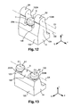
- FIGS 11 to 14 thus represent, without limitation, different variants of joint means 106, 122 comprising pivot joint means and ball joint means.
- the first hinge means 106 are constituted by at least one ball joint and the second hinge means 122 consist of at least two pivots 122A and 122B.
- the second articulation means 122 consist of first and second pivots, respectively 122A and 122B, so that the second axis of rotation 02 of the second fork 90 is a pivot axis determined by said pivots which, substantially transverse, is orthogonal to the longitudinal axis X of rotation.
- the first articulation means 106 carrying the internal articulating surface S are aligned longitudinally with the second articulation means 122 carrying the external articulation surfaces S1, S2 so that, with respect to the X axis longitudinal axis of rotation, the spacing of the first axis 01 of rotation of the first fork 88 is equal to the spacing between the second axis of rotation 02 of the second fork 90.
- the first axis of rotation O1 of the first fork 88 is coaxial with the second axis of rotation 02 of the second fork 90 so that the axes of rotation O1, O2 are merged and that the first and second forks 88, 90 have a common axis of rotation O.
- the first articulation means 106 carrying the internal articulating surface S are offset longitudinally and vertically with respect to the second articulation means 122 carrying the external articulation surfaces S1, S2 so that, with respect to the axis Longitudinal axis of rotation, the spacing of the first axis O1 of rotation of the first fork 88 is different from the center distance of the second axis of rotation 02 of the second fork 90.
- first axis of rotation O1 of the first fork 88 and the second axis of rotation 02 of the second fork 90 are at least vertically offset relative to each other so that the first and second forks 88, 90 have parallel axes of rotation 01, 02.
- the first hinge means 106 are constituted by an internal or central pivot 106 and the second hinge means 122 consist of a first ball 222A and a second ball 222B.
- the articulation means 106, 122 are, in comparison with the figure 13 , offset vertically between them so that the axes O1 and O2 are not included in a plane which is parallel to the axis X.
Landscapes
- Engineering & Computer Science (AREA)
- General Engineering & Computer Science (AREA)
- Mechanical Engineering (AREA)
- Mechanical Operated Clutches (AREA)
Claims (13)
- Doppelkupplungsmechanismus (10), insbesondere für Kraftfahrzeuge, der eine längs ausgerichtete Rotationsachse (X) aufweist und mindestens eine damit verknüpfte Betätigungsvorrichtung (12) umfasst, die zumindest eine erste Gabel (88) und eine zweite Gabel (90) umfasst, welche jeweils beweglich um eine erste Achse (O1) auf ersten Gelenkmitteln (106) und um eine zweite Achse (02) auf zweiten Gelenkmitteln (122) montiert sind, wobei die ersten Gelenkmittel (106, 206) mindestens eine als innere bezeichnete Gelenkfläche (S) der ersten Gabel (88) aufweisen und die zweiten Gelenkmittel (122, 122A, 122B, 222A, 222B) eine erste Gelenkfläche (S1) und eine zweite Gelenkfläche (S2) der zweiten Gabel (90) aufweisen, die als äußere Gelenkflächen bezeichnet werden, wobei die besagte innere Gelenkfläche (S) zwischen den besagten ersten und zweiten äußeren Gelenkflächen (S1, S2) angeordnet ist, dadurch gekennzeichnet, dass die erste Gabel (88) im Inneren der zweiten Gabel (90) untergebracht ist, die besagte erste und zweite Gabel (88, 90) einander konzentrisch übergreifen und in der Ruheposition im wesentlichen komplanar sind.
- Mechanismus (10) nach Anspruch 1, dadurch gekennzeichnet, dass die erste und zweite Gabel (88, 90) jeweils einen Hebel zweiter Ordnung bilden.
- Mechanismus (10) nach Anspruch 1, dadurch gekennzeichnet, dass die die innere Gelenkfläche (S) tragenden ersten Gelenkmittel (106, 206) in Längsrichtung derart mit den die äußeren Gelenkflächen (S1, S2) tragenden zweiten Gelenkmitteln (122, 122A, 122B, 222A, 222B) aneinandergereiht sind, dass bezogen auf die längs ausgerichtete Rotationsachse (X) der Achsabstand der ersten Rotationsachse (O1) der ersten Gabel (88) gleich ist dem Achsabstand der zweiten Rotationsachse (02) der zweiten Gabel (90).
- Mechanismus (10) nach Anspruch 1, dadurch gekennzeichnet, dass die die innere Gelenkfläche (S) tragenden ersten Gelenkmittel (106, 206) entlang der vertikalen Richtung, welche senkrecht zu der durch die Rotationsachse (X) definierten Längsrichtung verläuft, relativ zu den die äußeren Gelenkflächen (S1, S2) tragenden zweiten Gelenkmitteln (122, 122A, 122B, 222A, 222B) versetzt sind, so dass bezogen auf die besagte längs ausgerichtete Rotationsachse (X) der Achsabstand der ersten Rotationsachse (O1) der ersten Gabel (88) von dem Achsabstand der zweiten Rotationsachse (02) der zweiten Gabel (90) verschieden ist.
- Mechanismus (10) nach Anspruch 3, dadurch gekennzeichnet, dass die erste Rotationsachse (O1) der ersten Gabel (88) koaxial mit der zweiten Rotationsachse (02) der zweiten Gabel (90) ist, so dass die Rotationsachsen (01, 02) zusammenfallen und die erste und zweite Gabel (88, 90) eine gemeinsame Rotationsachse (O) aufweisen.
- Mechanismus (10) nach einem der Ansprüche 3 oder 4, dadurch gekennzeichnet, dass die erste Rotationsachse (O1) der ersten Gabel (88) und die zweite Rotationsachse (02) der zweiten Gabel (90) in Längsrichtung und/oder in Vertikalrichtung relativ zueinander versetzt sind, so dass die erste und zweite Gabel (88, 90) parallele Rotationsachsen (01, 02) aufweisen.
- Mechanismus (10) nach Anspruch 1, dadurch gekennzeichnet, dass die ersten Gelenkmittel (106) durch mindestens einen Drehzapfen (106) gebildet sind, so dass die erste Rotationsachse (O1) der ersten Gabel (88) eine Drehachse ist, die, in etwa quer ausgerichtet, senkrecht zu der längs ausgerichteten Rotationsachse (X) liegt.
- Mechanismus (10) nach Anspruch 1, dadurch gekennzeichnet, dass die ersten Gelenkmittel (106) durch mindestens einen Kugelkopf (206) gebildet sind, so dass die erste Gabel (88) um ein Rotationszentrum (C) herum rotatorisch beweglich montiert ist, dessen Überschneidung mit einer quer verlaufenden Referenz-Halbebene mit vertikaler und zu der längs ausgerichteten Rotationsachse (X) senkrechter Ausrichtung die besagte erste Rotationsachse (O1) der ersten Gabel (88) bestimmt.
- Mechanismus (10) nach Anspruch 1, dadurch gekennzeichnet, dass die zweiten Gelenkmittel (122) durch mindestens erste und zweite Drehzapfen (122A, 122B) gebildet sind, so dass die zweite Rotationsachse (02) der zweiten Gabel (90) eine durch die besagten Drehzapfen (122A, 122B) bestimmte Drehachse ist, die, in etwa quer ausgerichtet, senkrecht zu der längs ausgerichteten Rotationsachse (X) liegt.
- Mechanismus (10) nach Anspruch 1, dadurch gekennzeichnet, dass die zweiten Gelenkmittel (122) durch mindestens erste und zweite Kugelköpfe (222A, 222B) gebildet sind, so dass die zweite Gabel (90) um ein Rotationszentrum (C1, C2) von jedem Kugelkopf (222A, 222B) herum rotatorisch beweglich montiert ist, wobei die Rotationszentren (C1, C2) durch Überschneidung mit einer quer verlaufenden Referenz-Halbebene mit vertikaler und zu der längs ausgerichteten Rotationsachse (X) senkrechter Ausrichtung die besagte zweite Rotationsachse (02) der zweiten Gabel (90) bestimmen.
- Mechanismus (10) nach Anspruch 1, dadurch gekennzeichnet, dass die jeweiligen Gelenkmittel (106, 122) der besagten ersten und zweiten Gabel (88, 90) aus einem einzigen Stück ausgeführt sind, so dass das besagte Stück ein gemeinsames Gelenkmittel (106, 122) für die erste und zweite Gabel (88, 90) bildet, welches mit einem Gehäuse (14) des Mechanismus verbunden ist.
- Betätigungsvorrichtung (12) für einen Doppelkupplungsmechanismus (10), umfassend zumindest eine erste Gabel (88) und eine zweite Gabel (90), die in einer Betriebsposition angeordnet sind, in welcher die Gabeln (88, 90) für die Betätigung der besagten Kupplung (10) vereinigt sind, wobei die erste Gabel (88) einen Gelenkteil (98) aufweist, welcher zumindest eine Gelenkfläche (104) umfasst, und die zweite Gabel (90) einen Gelenkteil (114, 114A, 114B) aufweist, welcher eine erste und eine zweite Gelenkfläche (120A, 120B) umfasst, wobei die besagte Gelenkfläche (104) der ersten Gabel (88) in der Betriebsposition zwischen den besagten ersten und zweiten Gelenkflächen (120A, 120B) der zweiten Gabel (90) angeordnet ist, dadurch gekennzeichnet, dass die erste Gabel (88) im Inneren der zweiten Gabel (90) untergebracht ist, und dadurch, dass die besagte erste und zweite Gabel (88, 90) einander konzentrisch übergreifen und in der Ruheposition im wesentlichen komplanar sind.
- Betätigungsvorrichtung (12) nach Anspruch 12, dadurch gekennzeichnet, dass die Gelenkfläche (104) der ersten Gabel (88) dazu bestimm ist, mit zumindest einer komplementären inneren Gelenkfläche (S) der ersten Gelenkmittel (106, 206) zusammenzuwirken, und dadurch, dass die ersten und zweiten Gelenkflächen (120A, 120B) der zweiten Gabel (90) dazu bestimmt sind, jeweils mit einer komplementären ersten Gelenkfläche (S1) und einer komplementären zweiten Gelenkfläche (S2) der zweiten Gelenkmittel (122) zusammenzuwirken.
Applications Claiming Priority (2)
| Application Number | Priority Date | Filing Date | Title |
|---|---|---|---|
| FR0950590A FR2941755B1 (fr) | 2009-01-30 | 2009-01-30 | Mecanisme a double embrayage comportant un dispositif de commande a double fourchette |
| PCT/FR2010/050098 WO2010086540A1 (fr) | 2009-01-30 | 2010-01-22 | Mecanisme a double embrayage comportant un dispositif de commande a double fourchette |
Publications (2)
| Publication Number | Publication Date |
|---|---|
| EP2384403A1 EP2384403A1 (de) | 2011-11-09 |
| EP2384403B1 true EP2384403B1 (de) | 2013-08-14 |
Family
ID=40852494
Family Applications (1)
| Application Number | Title | Priority Date | Filing Date |
|---|---|---|---|
| EP10707573.1A Not-in-force EP2384403B1 (de) | 2009-01-30 | 2010-01-22 | Doppelkupplung mit doppelgabelbetätigung |
Country Status (5)
| Country | Link |
|---|---|
| EP (1) | EP2384403B1 (de) |
| KR (1) | KR101647529B1 (de) |
| CN (1) | CN102292564B (de) |
| FR (1) | FR2941755B1 (de) |
| WO (1) | WO2010086540A1 (de) |
Families Citing this family (4)
| Publication number | Priority date | Publication date | Assignee | Title |
|---|---|---|---|---|
| CN202597672U (zh) * | 2012-03-31 | 2012-12-12 | 比亚迪股份有限公司 | 一种双作用离合器操纵机构、双作用离合器及其汽车 |
| DE102012219496A1 (de) * | 2012-10-25 | 2014-04-30 | Schaeffler Technologies Gmbh & Co. Kg | Ausrückhebel |
| KR101448114B1 (ko) * | 2013-07-31 | 2014-10-13 | 주식회사평화발레오 | 분할형 액추에이터 하우징과 이를 이용한 클러치 액추에이터의 조립 방법 |
| KR101806699B1 (ko) * | 2016-05-31 | 2017-12-07 | 주식회사평화발레오 | 차량의 더블 클러치용 클러치 인게이지먼트 포크 조립체 |
Family Cites Families (8)
| Publication number | Priority date | Publication date | Assignee | Title |
|---|---|---|---|---|
| US4966267A (en) * | 1989-09-21 | 1990-10-30 | Borg-Warner Automotive Diversified Transmission Products Corporation | Ball screw actuated clutch combination |
| AU4565293A (en) | 1992-07-11 | 1994-01-31 | Luk Lamellen Und Kupplungsbau Gmbh | Clutch unit |
| EP1302688A3 (de) * | 2001-10-09 | 2004-07-28 | ZF Sachs AG | Betätigungseinrichtung für eine Reibungskupplungseinrichtung, gegebenenfalls Doppel- oder Mehrfach- Reibungskupplungseinrichtung |
| AU2003222726A1 (en) | 2002-03-27 | 2003-10-08 | Luk Lamellen Und Kupplungsbau Beteiligungs Kg | Clutch disengaging system for a twin clutch transmission of a motor vehicle |
| DE102004038456A1 (de) * | 2003-08-19 | 2005-03-17 | Zf Friedrichshafen Ag | Betätigungseinrichtung zur Betätigung der Kupplungsbereiche einer Doppelkupplung |
| FR2859773B1 (fr) * | 2003-09-16 | 2006-11-24 | Valeo Embrayages | Double embrayage, notamment pour vehicule automobile, a double butee de commande |
| DE102004007161A1 (de) * | 2004-02-12 | 2005-08-25 | Volkswagen Ag | Betätigungsvorrichtung zur Bewegung und/oder Verstellung von mindestens einem ersten Kupplungshebel und mindestens einem zweiten Kupplungshebel eines Getriebes |
| CN2864220Y (zh) * | 2006-02-23 | 2007-01-31 | 郭进华 | 汽车离合器自动控制器 |
-
2009
- 2009-01-30 FR FR0950590A patent/FR2941755B1/fr not_active Expired - Fee Related
-
2010
- 2010-01-22 CN CN2010800051291A patent/CN102292564B/zh active Active
- 2010-01-22 WO PCT/FR2010/050098 patent/WO2010086540A1/fr active Application Filing
- 2010-01-22 EP EP10707573.1A patent/EP2384403B1/de not_active Not-in-force
- 2010-01-22 KR KR1020117017308A patent/KR101647529B1/ko active IP Right Grant
Also Published As
| Publication number | Publication date |
|---|---|
| EP2384403A1 (de) | 2011-11-09 |
| KR20110119662A (ko) | 2011-11-02 |
| WO2010086540A1 (fr) | 2010-08-05 |
| KR101647529B1 (ko) | 2016-08-10 |
| CN102292564A (zh) | 2011-12-21 |
| FR2941755B1 (fr) | 2011-04-08 |
| CN102292564B (zh) | 2013-11-20 |
| FR2941755A1 (fr) | 2010-08-06 |
Similar Documents
| Publication | Publication Date | Title |
|---|---|---|
| FR2838169A1 (fr) | Systeme de debrayage pour un mecanisme a deux embrayages pour vehicule automobile. | |
| FR2954429A1 (fr) | Dispositif d'actionnement a came pour un systeme d'embrayage a friction. | |
| EP2384403B1 (de) | Doppelkupplung mit doppelgabelbetätigung | |
| EP3252333B1 (de) | Axiales einrastsystem für einen kupplungsmechanismus | |
| EP3580468B1 (de) | Lösbarer doppelkupplungsmechanismus | |
| EP2776728A1 (de) | Drehmomentübertragungseinheit, insbesondere für ein kraftfahrzeug | |
| WO2009037403A1 (fr) | Dispositif d'embrayage comportant un diaphragme qui exerce constamment un effort de precharge axial sur un palier d'un plateau de reaction | |
| FR2531511A1 (fr) | Timonerie de commande d'une piece menee, telle que butee de debrayage | |
| EP3959449B1 (de) | Getriebekasten und motor mit einem solchen getriebekasten | |
| WO2007085766A1 (fr) | Embrayage a diaphragme pousse | |
| FR2860845A1 (fr) | Double embrayage, notamment pour vehicule automobile | |
| EP3234396B1 (de) | Kupplungsvorrichtung für ein kraftfahrzeug | |
| WO2005028902A1 (fr) | Double embrayage, notamment pour vehicule automobile, a double butee de commande. | |
| FR3010159A1 (fr) | Dispositif d'embrayage a rattrapage d'usure | |
| BE1014007A3 (fr) | Embrayage, element de raccordement et dispositif forme de ceux-ci et procede d'assemblage d'un embrayage. | |
| EP2478239A1 (de) | Normal offene reibungskupplung mit vorrichtung zur unterstützung der rückkehr der membranfinger zur winkelruheposition | |
| EP2354582B1 (de) | Betätigungsvorrichtung mit Verschleissausgleich für eine Reibungskupplung | |
| EP2449278B1 (de) | Übertragungssystem mit einem modul mit integriertem doppelkupplungsmechanismus und steuervorrichtung dafür | |
| FR2834024A1 (fr) | Mecanisme d'embrayage, notamment pour vehicule automobile | |
| FR2995376A1 (fr) | Ensemble de transmission de couple comportant un double embrayage a sec et un volant amortisseur | |
| FR2951791A1 (fr) | Dispositif de commande pour un mecanisme d'embrayage presentant un encombrement longitudinal reduit. | |
| FR2896564A1 (fr) | Boite de vitesses robotisee a deux actionneurs. | |
| WO2023208996A1 (fr) | Dispositif de selection;boîte de vitesses; | |
| FR3013091A1 (fr) | Dispositif de changement de vitesse avec synchroniseur | |
| WO2019092385A1 (fr) | Dispositif et systeme de transmission de couple |
Legal Events
| Date | Code | Title | Description |
|---|---|---|---|
| PUAI | Public reference made under article 153(3) epc to a published international application that has entered the european phase |
Free format text: ORIGINAL CODE: 0009012 |
|
| 17P | Request for examination filed |
Effective date: 20110620 |
|
| AK | Designated contracting states |
Kind code of ref document: A1 Designated state(s): AT BE BG CH CY CZ DE DK EE ES FI FR GB GR HR HU IE IS IT LI LT LU LV MC MK MT NL NO PL PT RO SE SI SK SM TR |
|
| DAX | Request for extension of the european patent (deleted) | ||
| GRAP | Despatch of communication of intention to grant a patent |
Free format text: ORIGINAL CODE: EPIDOSNIGR1 |
|
| GRAS | Grant fee paid |
Free format text: ORIGINAL CODE: EPIDOSNIGR3 |
|
| GRAA | (expected) grant |
Free format text: ORIGINAL CODE: 0009210 |
|
| AK | Designated contracting states |
Kind code of ref document: B1 Designated state(s): AT BE BG CH CY CZ DE DK EE ES FI FR GB GR HR HU IE IS IT LI LT LU LV MC MK MT NL NO PL PT RO SE SI SK SM TR |
|
| REG | Reference to a national code |
Ref country code: GB Ref legal event code: FG4D Free format text: NOT ENGLISH |
|
| REG | Reference to a national code |
Ref country code: AT Ref legal event code: REF Ref document number: 627038 Country of ref document: AT Kind code of ref document: T Effective date: 20130815 Ref country code: CH Ref legal event code: EP |
|
| REG | Reference to a national code |
Ref country code: IE Ref legal event code: FG4D Free format text: LANGUAGE OF EP DOCUMENT: FRENCH |
|
| REG | Reference to a national code |
Ref country code: DE Ref legal event code: R096 Ref document number: 602010009414 Country of ref document: DE Effective date: 20131010 |
|
| REG | Reference to a national code |
Ref country code: NL Ref legal event code: VDEP Effective date: 20130814 Ref country code: AT Ref legal event code: MK05 Ref document number: 627038 Country of ref document: AT Kind code of ref document: T Effective date: 20130814 |
|
| REG | Reference to a national code |
Ref country code: LT Ref legal event code: MG4D |
|
| PG25 | Lapsed in a contracting state [announced via postgrant information from national office to epo] |
Ref country code: PT Free format text: LAPSE BECAUSE OF FAILURE TO SUBMIT A TRANSLATION OF THE DESCRIPTION OR TO PAY THE FEE WITHIN THE PRESCRIBED TIME-LIMIT Effective date: 20131216 Ref country code: HR Free format text: LAPSE BECAUSE OF FAILURE TO SUBMIT A TRANSLATION OF THE DESCRIPTION OR TO PAY THE FEE WITHIN THE PRESCRIBED TIME-LIMIT Effective date: 20130814 Ref country code: LT Free format text: LAPSE BECAUSE OF FAILURE TO SUBMIT A TRANSLATION OF THE DESCRIPTION OR TO PAY THE FEE WITHIN THE PRESCRIBED TIME-LIMIT Effective date: 20130814 Ref country code: AT Free format text: LAPSE BECAUSE OF FAILURE TO SUBMIT A TRANSLATION OF THE DESCRIPTION OR TO PAY THE FEE WITHIN THE PRESCRIBED TIME-LIMIT Effective date: 20130814 Ref country code: NO Free format text: LAPSE BECAUSE OF FAILURE TO SUBMIT A TRANSLATION OF THE DESCRIPTION OR TO PAY THE FEE WITHIN THE PRESCRIBED TIME-LIMIT Effective date: 20131114 Ref country code: IS Free format text: LAPSE BECAUSE OF FAILURE TO SUBMIT A TRANSLATION OF THE DESCRIPTION OR TO PAY THE FEE WITHIN THE PRESCRIBED TIME-LIMIT Effective date: 20131214 Ref country code: SE Free format text: LAPSE BECAUSE OF FAILURE TO SUBMIT A TRANSLATION OF THE DESCRIPTION OR TO PAY THE FEE WITHIN THE PRESCRIBED TIME-LIMIT Effective date: 20130814 Ref country code: CY Free format text: LAPSE BECAUSE OF FAILURE TO SUBMIT A TRANSLATION OF THE DESCRIPTION OR TO PAY THE FEE WITHIN THE PRESCRIBED TIME-LIMIT Effective date: 20130724 |
|
| PG25 | Lapsed in a contracting state [announced via postgrant information from national office to epo] |
Ref country code: GR Free format text: LAPSE BECAUSE OF FAILURE TO SUBMIT A TRANSLATION OF THE DESCRIPTION OR TO PAY THE FEE WITHIN THE PRESCRIBED TIME-LIMIT Effective date: 20131115 Ref country code: FI Free format text: LAPSE BECAUSE OF FAILURE TO SUBMIT A TRANSLATION OF THE DESCRIPTION OR TO PAY THE FEE WITHIN THE PRESCRIBED TIME-LIMIT Effective date: 20130814 Ref country code: LV Free format text: LAPSE BECAUSE OF FAILURE TO SUBMIT A TRANSLATION OF THE DESCRIPTION OR TO PAY THE FEE WITHIN THE PRESCRIBED TIME-LIMIT Effective date: 20130814 Ref country code: SI Free format text: LAPSE BECAUSE OF FAILURE TO SUBMIT A TRANSLATION OF THE DESCRIPTION OR TO PAY THE FEE WITHIN THE PRESCRIBED TIME-LIMIT Effective date: 20130814 Ref country code: PL Free format text: LAPSE BECAUSE OF FAILURE TO SUBMIT A TRANSLATION OF THE DESCRIPTION OR TO PAY THE FEE WITHIN THE PRESCRIBED TIME-LIMIT Effective date: 20130814 |
|
| PG25 | Lapsed in a contracting state [announced via postgrant information from national office to epo] |
Ref country code: CY Free format text: LAPSE BECAUSE OF FAILURE TO SUBMIT A TRANSLATION OF THE DESCRIPTION OR TO PAY THE FEE WITHIN THE PRESCRIBED TIME-LIMIT Effective date: 20130814 |
|
| PG25 | Lapsed in a contracting state [announced via postgrant information from national office to epo] |
Ref country code: RO Free format text: LAPSE BECAUSE OF FAILURE TO SUBMIT A TRANSLATION OF THE DESCRIPTION OR TO PAY THE FEE WITHIN THE PRESCRIBED TIME-LIMIT Effective date: 20130814 Ref country code: NL Free format text: LAPSE BECAUSE OF FAILURE TO SUBMIT A TRANSLATION OF THE DESCRIPTION OR TO PAY THE FEE WITHIN THE PRESCRIBED TIME-LIMIT Effective date: 20130814 Ref country code: EE Free format text: LAPSE BECAUSE OF FAILURE TO SUBMIT A TRANSLATION OF THE DESCRIPTION OR TO PAY THE FEE WITHIN THE PRESCRIBED TIME-LIMIT Effective date: 20130814 Ref country code: CZ Free format text: LAPSE BECAUSE OF FAILURE TO SUBMIT A TRANSLATION OF THE DESCRIPTION OR TO PAY THE FEE WITHIN THE PRESCRIBED TIME-LIMIT Effective date: 20130814 Ref country code: DK Free format text: LAPSE BECAUSE OF FAILURE TO SUBMIT A TRANSLATION OF THE DESCRIPTION OR TO PAY THE FEE WITHIN THE PRESCRIBED TIME-LIMIT Effective date: 20130814 Ref country code: SK Free format text: LAPSE BECAUSE OF FAILURE TO SUBMIT A TRANSLATION OF THE DESCRIPTION OR TO PAY THE FEE WITHIN THE PRESCRIBED TIME-LIMIT Effective date: 20130814 |
|
| PG25 | Lapsed in a contracting state [announced via postgrant information from national office to epo] |
Ref country code: ES Free format text: LAPSE BECAUSE OF FAILURE TO SUBMIT A TRANSLATION OF THE DESCRIPTION OR TO PAY THE FEE WITHIN THE PRESCRIBED TIME-LIMIT Effective date: 20130814 Ref country code: IT Free format text: LAPSE BECAUSE OF FAILURE TO SUBMIT A TRANSLATION OF THE DESCRIPTION OR TO PAY THE FEE WITHIN THE PRESCRIBED TIME-LIMIT Effective date: 20130814 |
|
| PLBE | No opposition filed within time limit |
Free format text: ORIGINAL CODE: 0009261 |
|
| STAA | Information on the status of an ep patent application or granted ep patent |
Free format text: STATUS: NO OPPOSITION FILED WITHIN TIME LIMIT |
|
| 26N | No opposition filed |
Effective date: 20140515 |
|
| BERE | Be: lapsed |
Owner name: VALEO EMBRAYAGES Effective date: 20140131 |
|
| REG | Reference to a national code |
Ref country code: DE Ref legal event code: R097 Ref document number: 602010009414 Country of ref document: DE Effective date: 20140515 |
|
| PG25 | Lapsed in a contracting state [announced via postgrant information from national office to epo] |
Ref country code: LU Free format text: LAPSE BECAUSE OF FAILURE TO SUBMIT A TRANSLATION OF THE DESCRIPTION OR TO PAY THE FEE WITHIN THE PRESCRIBED TIME-LIMIT Effective date: 20140122 |
|
| REG | Reference to a national code |
Ref country code: CH Ref legal event code: PL |
|
| GBPC | Gb: european patent ceased through non-payment of renewal fee |
Effective date: 20140122 |
|
| PG25 | Lapsed in a contracting state [announced via postgrant information from national office to epo] |
Ref country code: CH Free format text: LAPSE BECAUSE OF NON-PAYMENT OF DUE FEES Effective date: 20140131 Ref country code: LI Free format text: LAPSE BECAUSE OF NON-PAYMENT OF DUE FEES Effective date: 20140131 |
|
| REG | Reference to a national code |
Ref country code: IE Ref legal event code: MM4A |
|
| PG25 | Lapsed in a contracting state [announced via postgrant information from national office to epo] |
Ref country code: GB Free format text: LAPSE BECAUSE OF NON-PAYMENT OF DUE FEES Effective date: 20140122 |
|
| PG25 | Lapsed in a contracting state [announced via postgrant information from national office to epo] |
Ref country code: BE Free format text: LAPSE BECAUSE OF NON-PAYMENT OF DUE FEES Effective date: 20140131 Ref country code: IE Free format text: LAPSE BECAUSE OF NON-PAYMENT OF DUE FEES Effective date: 20140122 |
|
| PG25 | Lapsed in a contracting state [announced via postgrant information from national office to epo] |
Ref country code: MC Free format text: LAPSE BECAUSE OF FAILURE TO SUBMIT A TRANSLATION OF THE DESCRIPTION OR TO PAY THE FEE WITHIN THE PRESCRIBED TIME-LIMIT Effective date: 20130814 |
|
| REG | Reference to a national code |
Ref country code: FR Ref legal event code: PLFP Year of fee payment: 7 |
|
| PG25 | Lapsed in a contracting state [announced via postgrant information from national office to epo] |
Ref country code: MT Free format text: LAPSE BECAUSE OF FAILURE TO SUBMIT A TRANSLATION OF THE DESCRIPTION OR TO PAY THE FEE WITHIN THE PRESCRIBED TIME-LIMIT Effective date: 20130814 |
|
| PG25 | Lapsed in a contracting state [announced via postgrant information from national office to epo] |
Ref country code: SM Free format text: LAPSE BECAUSE OF FAILURE TO SUBMIT A TRANSLATION OF THE DESCRIPTION OR TO PAY THE FEE WITHIN THE PRESCRIBED TIME-LIMIT Effective date: 20130814 |
|
| PG25 | Lapsed in a contracting state [announced via postgrant information from national office to epo] |
Ref country code: BG Free format text: LAPSE BECAUSE OF FAILURE TO SUBMIT A TRANSLATION OF THE DESCRIPTION OR TO PAY THE FEE WITHIN THE PRESCRIBED TIME-LIMIT Effective date: 20130814 |
|
| PG25 | Lapsed in a contracting state [announced via postgrant information from national office to epo] |
Ref country code: TR Free format text: LAPSE BECAUSE OF FAILURE TO SUBMIT A TRANSLATION OF THE DESCRIPTION OR TO PAY THE FEE WITHIN THE PRESCRIBED TIME-LIMIT Effective date: 20130814 Ref country code: HU Free format text: LAPSE BECAUSE OF FAILURE TO SUBMIT A TRANSLATION OF THE DESCRIPTION OR TO PAY THE FEE WITHIN THE PRESCRIBED TIME-LIMIT; INVALID AB INITIO Effective date: 20100122 |
|
| REG | Reference to a national code |
Ref country code: FR Ref legal event code: PLFP Year of fee payment: 8 |
|
| REG | Reference to a national code |
Ref country code: FR Ref legal event code: PLFP Year of fee payment: 9 |
|
| PG25 | Lapsed in a contracting state [announced via postgrant information from national office to epo] |
Ref country code: MK Free format text: LAPSE BECAUSE OF FAILURE TO SUBMIT A TRANSLATION OF THE DESCRIPTION OR TO PAY THE FEE WITHIN THE PRESCRIBED TIME-LIMIT Effective date: 20130814 |
|
| PGFP | Annual fee paid to national office [announced via postgrant information from national office to epo] |
Ref country code: DE Payment date: 20200113 Year of fee payment: 11 |
|
| PGFP | Annual fee paid to national office [announced via postgrant information from national office to epo] |
Ref country code: FR Payment date: 20200131 Year of fee payment: 11 |
|
| REG | Reference to a national code |
Ref country code: DE Ref legal event code: R119 Ref document number: 602010009414 Country of ref document: DE |
|
| PG25 | Lapsed in a contracting state [announced via postgrant information from national office to epo] |
Ref country code: FR Free format text: LAPSE BECAUSE OF NON-PAYMENT OF DUE FEES Effective date: 20210131 |
|
| PG25 | Lapsed in a contracting state [announced via postgrant information from national office to epo] |
Ref country code: DE Free format text: LAPSE BECAUSE OF NON-PAYMENT OF DUE FEES Effective date: 20210803 |