EP2384403B1 - Dual clutch with a double fork actuator - Google Patents
Dual clutch with a double fork actuator Download PDFInfo
- Publication number
- EP2384403B1 EP2384403B1 EP10707573.1A EP10707573A EP2384403B1 EP 2384403 B1 EP2384403 B1 EP 2384403B1 EP 10707573 A EP10707573 A EP 10707573A EP 2384403 B1 EP2384403 B1 EP 2384403B1
- Authority
- EP
- European Patent Office
- Prior art keywords
- fork
- articulation
- rotation
- rotational axis
- axis
- Prior art date
- Legal status (The legal status is an assumption and is not a legal conclusion. Google has not performed a legal analysis and makes no representation as to the accuracy of the status listed.)
- Not-in-force
Links
Images


Classifications
-
- F—MECHANICAL ENGINEERING; LIGHTING; HEATING; WEAPONS; BLASTING
- F16—ENGINEERING ELEMENTS AND UNITS; GENERAL MEASURES FOR PRODUCING AND MAINTAINING EFFECTIVE FUNCTIONING OF MACHINES OR INSTALLATIONS; THERMAL INSULATION IN GENERAL
- F16D—COUPLINGS FOR TRANSMITTING ROTATION; CLUTCHES; BRAKES
- F16D23/00—Details of mechanically-actuated clutches not specific for one distinct type
- F16D23/12—Mechanical clutch-actuating mechanisms arranged outside the clutch as such
-
- F—MECHANICAL ENGINEERING; LIGHTING; HEATING; WEAPONS; BLASTING
- F16—ENGINEERING ELEMENTS AND UNITS; GENERAL MEASURES FOR PRODUCING AND MAINTAINING EFFECTIVE FUNCTIONING OF MACHINES OR INSTALLATIONS; THERMAL INSULATION IN GENERAL
- F16D—COUPLINGS FOR TRANSMITTING ROTATION; CLUTCHES; BRAKES
- F16D21/00—Systems comprising a plurality of actuated clutches
- F16D21/02—Systems comprising a plurality of actuated clutches for interconnecting three or more shafts or other transmission members in different ways
-
- F—MECHANICAL ENGINEERING; LIGHTING; HEATING; WEAPONS; BLASTING
- F16—ENGINEERING ELEMENTS AND UNITS; GENERAL MEASURES FOR PRODUCING AND MAINTAINING EFFECTIVE FUNCTIONING OF MACHINES OR INSTALLATIONS; THERMAL INSULATION IN GENERAL
- F16D—COUPLINGS FOR TRANSMITTING ROTATION; CLUTCHES; BRAKES
- F16D23/00—Details of mechanically-actuated clutches not specific for one distinct type
- F16D23/12—Mechanical clutch-actuating mechanisms arranged outside the clutch as such
- F16D23/14—Clutch-actuating sleeves or bearings; Actuating members directly connected to clutch-actuating sleeves or bearings
- F16D2023/141—Clutch-actuating sleeves or bearings; Actuating members directly connected to clutch-actuating sleeves or bearings characterised by using a fork; Details of forks
Definitions
- the present invention relates to a dual clutch mechanism having a dual fork control device.
- the present invention more particularly relates to a double clutch mechanism according to the preamble of claim 1.
- Such a dual clutch mechanism is used in particular to alternately couple the shaft of a vehicle engine with two coaxial input shafts of a gearbox, said double clutch gearbox.
- the double-clutch mechanism also known as a double clutch, makes it possible to change gears while maintaining the transmission of engine torque to the wheels of the vehicle.
- the double clutch mechanism generally comprises a first clutch and a second clutch respectively associated with even and odd gear ratios.
- the first clutch is disengaged while the second clutch is engaged so that the engine torque is transferred progressively from the first clutch to the second clutch.
- the sum of the torques transmitted by the first and second clutches is always substantially equal to the engine torque.
- the double clutch mechanism further comprises a fixed housing defining a volume in which are housed the two gearshift clutches of different ratios.
- Each clutch mechanism includes a diaphragm for cooperating with a pressure plate integral in rotation of the cover and the motor shaft.
- Each diaphragm is movable, by means of a corresponding control stop, between at least a first position and a second position.
- Each pressure plate urged by the corresponding diaphragm, is intended to grip a friction disc between this pressure plate and a corresponding reaction plate.
- each friction disk is rotatably connected to a corresponding gearbox shaft and each pressure plate is rotatably connected to a cover, generally connected to the drive shaft by connecting means such as a steering wheel. flexible or double damping flywheel.
- Such a mechanism is equipped with an associated control device mainly comprising actuating means able to selectively bias each of the first and second forks intended to actuate between two extreme positions of the first and second control stops respectively controlling the displacement of each of the diaphragms of the first and second clutches.
- the ranges of the control device are articulated each around a ball joint respectively fixed to the casing of the mechanism and arranged radially closer to each other, that is to say arranged l one below the other in a vertical orientation, conventionally defined as orthogonal to the longitudinal orientation which is determined by the above-mentioned X axis of rotation of the mechanism, which is also the main axis of the control stops driven by the forks.
- the figures 7 and 8 illustrate an example of a control device for a double clutch mechanism comprising two forks respectively forming levers of the first kind and which are arranged on either side of the axis of rotation.
- FIGS 9 to 11 illustrate another example of a control device for a double-clutch mechanism comprising two forks respectively forming levers of the first kind and which are arranged on the same side of the axis of rotation and longitudinally juxtaposed, that is to say arranged side by side side by side of the means of articulation.
- the arrangement of the hinge means is sometimes difficult, in particular because of implantation constraints, only a reduced space being available to accommodate the actuating means, the forks and the associated hinge means.
- the forks must be able to actuate the control stops with a sufficient stroke to satisfactorily perform the clutch or disengagement operations for each of the clutches of the mechanism .
- the invention is intended in particular to improve the control device of a double clutch while maintaining for each a simple structure, a particularly small footprint and efficient operation.
- the subject of the invention is a double clutch mechanism of the type described above, characterized in that the first fork is housed inside the second fork, said first and second concentric forks are nested one inside the other and are, in the rest position, globally coplanar.
- the implantation of the forks and the associated hinge means can be achieved in a smaller overall space, both radially than in the longitudinal direction.
- said axes of rotation of the forks are located on the same side of the X axis.
- the rotation axes of the forks are arranged so that, relative to a reference horizontal plane passing through the longitudinal axis X of rotation of the mechanism, the first axis of rotation and the second axis of rotation are of the same side of the reference plane thus defined, that is to say in the vertical direction orthogonal to said plane, either above or below.
- the arrangement of the hinge means of the forks has a smaller footprint in the radial direction and in the longitudinal direction or, with congestion radial equivalent, an upper lever length for at least one of the forks.
- the implantation of the hinge means associated with the forks is also simplified by the use of a hinge piece common to the forks.
- the common hinge part is connected to the housing of the mechanism from the front radial face or bottom of which the piece extends axially or longitudinally forwards through a foot having a predetermined length.
- control device comprising the forks whose axis of rotation, preferably a common pivot axis, carried by such a common part is likely to be disposed axially further forward with respect to the face of the casing so that the stroke performed by the thrust actuated by the fork is maximum and obtained for a corresponding stroke of the actuating means is minimal.
- each of the first and second forks is completely independent and the forks may be selectively displaced by actuating means, without any interaction between one and the other of said ranges, the forces applied to one being in particular not transmitted to the other and vice versa.
- the hinge means of the first fork and the second fork are, in a non-limiting manner, respectively constituted by a pivot and / or a ball joint.
- the invention further relates to a control device for a double clutch mechanism according to claim 12.
- the articulation surface of the first fork is intended to cooperate with at least one inner articulation surface complementary to the first articulation means and the first and second articulation surfaces of the second fork are intended to cooperate respectively with a first hinge surface and a second hinge surface complementary to the second hinge means.
- the terms “upper” and “lower” correspond respectively to the top and the bottom of the figure 1 and are determined according to the vertical orientation of the trihedron (L, V, T) and the terms “external” and “internal” are determined according to the transverse orientation of the trihedron (L, V, T), which vertical and transverse orientations are orthogonal to the aforementioned longitudinal axis X.
- an "axial" axial direction is also determined along the longitudinal axis X and a "radial” direction which, orthogonal to said axial direction, designates elements extending overall in a vertical plane (V, T) of transverse orientation.
- an exemplary embodiment of a double-clutch mechanism which, in particular for equipping a motor vehicle, is designated by the general reference 10 and has an axis X of rotation, here of longitudinal orientation according to the trihedron (L, V, T).
- the double clutch mechanism 10 comprises an associated control device 12 comprising at least a double fork, more particularly illustrated in detail in FIGS. figures 2 and 3 according to a preferred embodiment of the invention.
- the double clutch mechanism 10 is housed, with at least a part of the control device 12, inside a volume delimited by a housing 14.
- the two driven shafts 16A and 16B of the mechanism 10 are concentric and are rotatably mounted coaxially with the drive shaft, the first driven shaft 16A forms a tube inside which the second driven shaft 16B is arranged.
- a free front end portion of the second driven shaft 16B extends longitudinally beyond the forward end of the first driven shaft 16A, each of said driven shafts 16A and 16B being rotatable independently of each other.
- the driven shafts 16A and 16B are intended to be connected to a gearbox (not shown) arranged longitudinally at the rear, that is to say on the right of the figure 1 beyond the fixed housing 14.
- first driven shaft 16A corresponds to certain gear ratios of the gearbox, for example the even gear ratios
- second driven shaft 16B corresponds to the other gear ratios, e.g. odd gear ratios.
- the double clutch mechanism 10 comprises a first clutch E1 and a second clutch E2 for temporarily coupling one of the driven shafts 16A, 16B to the drive shaft and which are selectively controlled by the control device 12 so as to respectively allow the passage of gear ratios of different parities.
- the mechanism 10 comprises a circular radial reaction plate 18 which is rotatably mounted about the longitudinal axis X of rotation, via a bearing, preferably constituted by a ball bearing 20.
- the reaction plate 18 is integral in rotation with the motor shaft.
- the mechanism 10 comprises connecting means 22 with the motor shaft, said means 22 being arranged at a longitudinal end front of the mechanism 10 and able to be fixed coaxially to the motor shaft.
- such connecting means are for example constituted by a flexible circular radial disk 22.
- the connecting means 22 also provide a damping and / or filtration function and are for example constituted by a double damping flywheel .
- the first clutch E1 of the mechanism 10 forms first temporary coupling means of the first driven shaft 16A with the motor shaft.
- the first clutch E1 comprises a first annular pressure plate 24 which is mounted to rotate with the reaction plate 18 about the axis X of rotation.
- the first pressure plate 24 is more particularly arranged axially vis-à-vis a rear face 26 of the reaction plate 18.
- the first pressure plate 24 is mounted to slide axially relative to the reaction plate 18.
- the first pressure plate 24 is mounted to slide axially on axial columns 28 which are fixed to the periphery of the reaction plate 18.
- the first clutch E1 comprises a first coaxial friction disk 30 which is interposed axially between the reaction plate 18 and the first pressure plate 24.
- the first friction disk 30 has on both its faces an annular friction lining 32 which is arranged axially vis-à-vis the first pressure plate 24 and the reaction plate 18.
- the first friction disc 30 is rotatably mounted to the first driven shaft 16A, and is axially slidably mounted on the first tubular driven shaft 16A between a tight front position ( figure 4 ) against the rear face 26 of the reaction plate 18 and a free rear position ( figure 1 to which it is resiliently biased and in which the first friction disc 30 is moved away from the rear face 26 of the reaction plate 18.
- the first diaphragm 34 has a radially outer ring 35 and elastic fingers 36 extending radially towards the axis X of rotation from the ring 35 to a free inner end 38. All the fingers 36 of the first diaphragm 34 are preferably identical.
- the first rear cover 40 more particularly comprises an annular radial bottom 42 and a cylindrical axial skirt 44 extending forwardly from the outer periphery of the bottom 42 to the peripheral portion of the reaction plate 18, surrounding the first pressure plate 24.
- the ring 35 of the first diaphragm 34 is for example fixed on a front face of the bottom 42 of the first cover 40 by means of a flange 47 having tabs which extend radially inwards.
- the flange 47 is fixed to the first cover 40 by rivets 48 so that the ring 35 of the first diaphragm 34 is axially clamped against the bottom 42 of the first cover 40 by the radial tabs of the flange 47.
- each finger 36 of the first diaphragm 34 is axially supported on an annular portion 50 of the first pressure plate 24.
- the fingers 36 of the first diaphragm 34 thus function in the manner of a lever which is supported by its end upper against the first fixed cover 40.
- the fingers 36 of the first diaphragm 34 are elastically flexible, in particular the free end 38 of the fingers 36 which is displaced between an extreme forward clutch position shown in FIG. figure 4 and an extreme rear declutching position shown in FIG. figure 1 or 5 .
- the first diaphragm 34 axially urges the first pressure plate 24 to clamp the first friction disk 30 against the reaction plate 18.
- the first pressure plate 24 In the extreme rear declutching position towards which the fingers 36 are resiliently biased, the first pressure plate 24 is no longer biased axially by the first diaphragm 34 so that the first friction disc 30 is then in its free rear position, as represented at figure 1 or 5 .
- the second clutch E2 comprises a second pressure plate 52 and a second friction disk 54 whose functions are respectively similar to those of the first pressure plate 24 and the first friction disk 30.
- the second pressure plate 52 is mounted axially vis-à-vis the front face 56 of the reaction plate 18.
- the second pressure plate 52 is rotationally integral with the reaction plate 18 via a second cover 58 which has a rear radial annular bottom 60 and a cylindrical axial skirt 62 which extends forward to second pressure plate 52 surrounding the first cover 40. More particularly, the second cover 58 is connected to the periphery of the second pressure plate 52.
- the second cover 58 is thus integral with the second pressure plate 52 in rotation and in axial sliding.
- the second coaxial friction disc 54 is interposed axially between the reaction plate 18 and the second pressure plate 52. It also comprises on its two faces an annular friction lining 64 which is interposed axially between the front face 56 of the reaction plate. 18 and the second pressure plate 52.
- the second friction disc 54 is intended to be clamped against the front face 56 of the reaction plate 18 by the second pressure plate 52 to temporarily couple the second driven shaft 16B with the motor shaft.
- the second friction disc 54 is rotatably mounted to the second driven shaft 16B, and is axially slidably mounted on the front end portion of the second driven shaft 16B between a rear position clamped against the front face 56 of the reaction plate 18 and a free front position to which it is resiliently biased and wherein the second friction disc 54 is remote from the front face 56 of the reaction plate 18.
- the very low axial clearance existing, in the free rear position, between the second friction disk 54 and the front face 56 of the reaction plate 18 has not been represented at the figure 1 .
- the second clutch E2 comprises a second rear axial annular diaphragm 66 for actuating the second pressure plate 52.
- the second diaphragm 66 has a structure similar to that of the first diaphragm 34.
- the second diaphragm 66 is arranged axially behind the first diaphragm 34. It is interposed axially between the edge 46 of the first cover 40 and a front face of the bottom 60 of the second cover 58. More particularly, the ring 67 of the second diaphragm 66 is arranged in axial support against a front face of the bottom 60 of the second cover 58.
- the second diaphragm 66 is for example held in position by rivets (not shown) which are fixed to the first cover 40.
- the rivets are then arranged between two consecutive fingers 68 of the second diaphragm 66 with an axial play.
- the second diaphragm 66 is held in position while allowing the fingers 68 to bend.
- the fingers 68 of the second diaphragm 66 operate in the manner of a lever.
- an axial actuation force which is applied forward to the free end 70 of the fingers 68 is transmitted to the cover 34, the fingers 68 bearing on the edge 46 of the first cover 34, then to the central plate 18 .
- the fingers 68 of the second diaphragm 66 are elastically flexible between an extreme forward clutch position which is shown in FIG. figure 5 and wherein the second diaphragm 66 axially biases rearwardly the second pressure plate 52 to clamp the first friction disk 54 against the reaction plate 18 via the second cover 58, and a rearward disengaging extreme position towards which the fingers 68 are elastically biased and wherein the second pressure plate 52 is no longer biased axially so that the second friction disk 54 is in its free forward position, as shown in FIG. figure 1 .
- the mechanism 10 further comprises the associated control device 12 which is intended to independently control, on the one hand, the first diaphragm 34 of the first clutch E1 between the extreme positions before clutch and disengagement rear and secondly the second diaphragm 66 of the second clutch E2 between the extreme front positions of clutch and rear clutch.
- control device 12 comprises a first annular stop 72 for actuating the first diaphragm 34 which is slidably mounted axially between an extreme forward clutch position, as illustrated in FIG. figure 4 , in which the stop 72 axially urges forward the free end 38 of the fingers 36 of the first diaphragm 34 in their extreme forward clutch position and an extreme rear declutching position, as illustrated in FIG. figure 1 or 5 .
- the control device 12 also comprises a second annular abutment 74 for actuating the second diaphragm 66 which is slidably mounted axially between an extreme front clutch position in which the abutment 74 axially biases forward the free end 70 of the fingers 68 of the second diaphragm 66 in their extreme forward clutch position, as illustrated in FIG. figure 5 , and an extreme rear declutching position, as illustrated in FIG. figure 1 or 4 .
- the first and second stops 72, 74 for actuation are respectively fixed on a first and a second sleeve 76, 78 axial sliding.
- the sleeves 76, 78 are slidably mounted on a tubular guide 80 having, in axial section, generally an "L" shape.
- the sleeves 76, 78 are mounted on a tubular axial portion of the guide 80 which extends forwardly from another radial portion forming a fixing flange extending radially outwardly.
- the guide 80 is fixed via the portion forming the radial flange to a front face 82 of the casing 14, for example by rivets 81.
- the first sleeve 76 is slidably mounted inside the tubular guide 80 against an inner cylindrical face 84 of the guide 80, while the second sleeve 78 is slidably mounted outside the tubular guide 80 on an outer cylindrical face 86 of the guide 80.
- the first sleeve 76 is slidably mounted around the tubular guide 80 against the outer cylindrical face 86 of the guide 80 and the second sleeve 78 is mounted around the first sleeve 76 so that the second sleeve 78 slides axially on the face outer cylindrical first sleeve 76.
- the first sleeve 76 is then interposed radially between the guide 80 and the second sleeve 78.
- Each stop 72, 74 can be slidably controlled by means of an associated fork, respectively a first fork 88 and a second fork 90, which are of generally radial orientation.
- the first fork 88 comprises a body 92 of generally oval shape and which comprises respectively, from the outside towards the inside in the radial direction, a portion operating member 94, an actuating portion 96 and a hinge portion 98.
- the operating portion 94 of the first fork 88 is intended to cooperate with first actuating means 100 able to exert selectively on said portion 94 a determined actuating force F1 capable of causing the displacement of the first fork 88 from a position back rest ( figure 1 ) to a position before work ( figure 4 ) corresponding to the extreme forward clutch position of the control stop 72 and the first diaphragm 34 of the first clutch E1.
- the body 92 of the first fork 88 then divides into two branches 92A, 92B each comprising a bulge which forms the actuating portion 96 intended to cooperate with the first sleeve 76 for controlling the sliding of the first stop 72 on the guide 80 .
- the two branches 92A and 92B transversely delimit, with the actuating part 94 and with the articulation part 98 arranged at each vertical end of said branches 92A, 92B of the first fork 88, a central opening 102 intended to be traversed longitudinally by the means for actuating the stops 72, 74, in particular the sleeves 76, 78 and the guide 80.
- the branches 92A, 92B of the body 92 then join to form the hinge portion 98 of the first fork 88.
- the hinge portion 98 comprises a hinge surface 104, here formed in the rear vertical face of the portion 298, which is intended to cooperate with first hinge means 106 of the first fork 88 mounted movably around a first axis of rotation 01.
- the first articulation means 106 comprise at least one so-called internal articulation surface S which is complementary to the articulation surface 104 carried by the articulation portion 98 of the first fork 88.
- the second fork 90 comprises a body 108 which, also of generally oval shape, respectively comprises, from the outside towards the inside in the radial direction, an operating part 110, an actuating part 112 and an articulation part. 114.
- the operating portion 110 of the second fork 90 is intended to cooperate with second actuating means 116 capable of exerting selectively on said portion 110 an actuating force F2 determined to cause the displacement of the second fork 90 from a position back rest ( figure 1 ) to a position before work ( figure 5 ) corresponding to the extreme front position clutch of the control stop 74 and the second diaphragm 66 of the second clutch E2.
- the body 108 of the second fork 90 then divides into two branches 108A, 108B each having a flat part which forms the actuating portion 112 intended to cooperate with the second sleeve 78 for controlling the sliding of the second stop 74 on the guide 80 .
- the two branches 108A and 108B delimit transversely with the actuating portion 112 and the hinge portion 114 at each vertical end of the second fork 90, a central opening 118 for to be traversed longitudinally by the actuating means of the stops 72, 74, in particular the sleeves 76, 78 and the guide 80.
- the central opening 118 of the second fork 90 determines an internal space inside which is arranged, globally concentrically, the first fork 88.
- Each arm 114A, 114B comprises on a rear radial face a hinge surface, respectively 120A and 120B, intended to cooperate with second hinge means of the second fork 90 which is mounted to move about a second axis of rotation 02 .
- the two arms 114A and 114B of the hinge portion 114 of the second fork 90 are generally parallel and delimit between them a housing in which the hinge portion 98, 298 of the first fork 88 penetrates so that the parts
- the hinges 98 and 114 of the forks are substantially nested one inside the other.
- first fork 88 and the second fork 90 are shaped to operate without interaction with each other so that, when moving around the second hinge means 122 associated, the second fork 90 does not enter into operation. contact with the first fork 88 and vice versa.
- the second articulation means 122 respectively comprise a first articulation surface S1 complementary to the hinge surface 120A of the arm 114A of the second fork 90 and a second hinge surface S2 complementary to the hinge surface 120B of the arm 114B of the second fork 90, said articulation surfaces S1 and S2 of the second hinge means 122 are said to be external in comparison with the internal hinge surface S of the first fork 88.
- the inner articulation surface S of the first fork 88 is arranged between said first and second outer articulation surfaces S1 and S2 of the second fork 90.
- the inner surface S is thus arranged transversely between the outer surfaces S1 and S2, said articulation surfaces S, S1 and S2 are juxtaposed next to each other so as to obtain a particularly compact and compact arrangement and this in all the orientations of the trihedron (L, V, T).
- the hinge portions 98 and 114 of the first and second forks 88 and 90 interpenetrate so that the hinge portion 98 is generally transverse between the arms 114A and 114B.
- Each of the forks 88, 90 constitutes a said lever of the second kind, that is to say by definition a lever in which the resistant force is exerted between the axis of rotation and the driving force, for example remember that a nutcracker is such a lever of the second kind.
- the rear rest position of the first fork 88 and the second fork 90 is determined by stop means (not shown) which are for example carried by the front face 82 of the casing 14 adjacent.
- the mechanism 10 advantageously comprises stop means able to limit the displacement of the forks 88, 90 and / or control stops 72, 74 axially forwardly, beyond a determined position, which is likely to occur after significant wear of the linings of each of the friction discs 30 and 54.
- the first fork 88 is movably mounted on the first articulation means 106 and around a first axis 01 while the second fork 90 is movably mounted on the second articulation means 122 and around a second axis 02.
- first hinge means 106 carrying the inner hinge surface S are aligned longitudinally with the second hinge means 122 carrying the hinge outer surfaces S1 and S2 so that the spacing of the first axis of rotation O1 of the first fork 88 is equal to the center distance of the second axis of rotation 02 of the second fork 90, the center distance referenced "e" on the figure 1 corresponding to the radial distance of each of the axes 01, 02 relative to the longitudinal axis X of rotation.
- the implantation of the forks 88 and 90 can be performed in a smaller overall size than before, especially with a smaller footprint in the radial direction compared to the state of the art.
- the axes of rotation O1 and O2 of the forks are located on the same side of the longitudinal axis X of rotation, whereby the first and second forks 88 and 90 extend on the same side of the axis X with an arm optimal leverage.
- the actuating means 100 and 116 respectively associated with the forks 88 and 90 are situated on the same side of the longitudinal axis X of rotation.
- control device 12 particularly compact and without sacrificing the performance of said device in general and forks 88 and 90 in particular.
- the points of intersection of the axes of rotation 01, 02 and a reference plane of vertical orientation passing through said longitudinal axis X of rotation are located in the same vertical half-plane.
- first and second forks 88 and 90 extend radially in the same plane and are, in rest position, globally coplanar.
- first and second forks 88 and 90 are concentric, the first fork 88 being housed inside the second fork 90.
- the first axis of rotation 01 and the second axis of rotation O2 are more particularly represented in FIG. figure 2 .
- the first and second forks 88, 90 thus have a common axis of rotation O which is therefore the only axis of rotation shown in some of the figures since, carried by the articulation means, the common axis O constitutes the axis of rotation 01 and the axis of rotation 02 respectively.
- the first articulation means 106 are constituted by a first pivot 106 so that the first axis of rotation 01 of the first fork 88, advantageously formed by the common axis O, is a pivot axis which, substantially transverse orientation, is orthogonal to the longitudinal axis of rotation X.
- the second hinge means 122 are constituted by a second pivot 122 so that the second axis of rotation 02 of the second fork 90, also formed by the common axis O, is a pivot axis which, d ' substantially transverse orientation, is orthogonal to the longitudinal axis X of rotation.
- the first fork 88 as the second fork 90 are mounted movably, between their respective rear positions of rest and before work, respectively about a first pivot axis 01 worn. by the first hinge 106 and a second pivot axis 02 carried by the second hinge means 122.
- the axes O1 and O2 of pivoting are therefore constituted by a single single common axis O of pivoting which is advantageously carried by a single hinge means forming both the first hinge means 106 of the first fork 88 and the second means hinge 122 of the second fork 90.
- first hinge means 106 of the first fork 88 and the second hinge means 122 of the second fork 90 are distinct and consist of at least two pivots arranged transversely next to each other to present the same pivot axis O.
- the respective hinge means 106, 122 of said first and second forks 88, 90 are thus advantageously made in one piece which is preferably linked to the casing 14 so that said piece forms a common hinge means for the first and second forks 88, 90.
- said piece forming a common pivot of the first and second forks 88, 90 comprises a single hinge surface 124 forming respectively the inner hinge surface S and the first and second outer hinge surfaces S1 and S2, said surface 124 thus being complementary to the respective hinge surfaces 104 and 120A, 120B of the hinge parts 98 and 114 of the first and second forks 88, 90.
- the common pivot 106-122 comprises axially at the front a head 123 bearing said single hinge surface 124 of the forks 88, 90 and, axially behind said head 123, a foot 125 which extends axially up to the face 82 of the casing 14.
- the foot 125 of the common pivot 106-122 is integral with the casing 14 and the pivot is made integrally, in one piece, with the casing 14.
- the common pivot 106-122 is a separate part which is attached to the face 82 of the casing by any appropriate means, for example by welding.
- the respective hinge surfaces 104 and 120A, 120B of the first and second forks 88, 90 on the one hand, and the single hinge surface 124 of the common pivot on the other hand, are intended to cooperate together to form a pivoting joint around the common axis O and said surfaces are constituted by cylindrical surfaces, here of generally circular section.
- the common pivot 106-122 forming the hinge means of the forks 88 and 90 is connected to the casing 14 by means of its foot 125 which extends axially forwardly, here rectilinearly, from the face 82 forming the bottom of the housing 14 of the mechanism 10.
- the common axis O of pivoting of the forks 88 and 90 is carried by the common pivot 106-122, which common pivot is likely to be, compared with the state of the art, arranged axially further forward by relative to the face 82 of the casing 14.
- each control stop 72, 74 actuated by the associated fork 88, 90 is maximum and obtained for a corresponding stroke of the actuating means 100 and 116 which is advantageously minimal.
- the arms 114A and 114B are interconnected by a portion of the body 108 which forms a bridge extending transversely between them so as to facilitate the machining of each of the surfaces 120A and 120B.
- the second fork 90 thus has an overall rigidity, in particular in its hinge portion 114, able also to avoid any contact with the first fork 88 which is arranged inside its body 108 and whose part d articulation 98 is interposed transversely between the arms 114A and 114B.
- the articulation surfaces 104, 120A and 120B of the forks 88 and 90 are machined simultaneously in a single operation for a greater precision with respect to the single hinge surface 124 complementary to the common pivot 106-122.
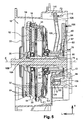
- figures 4 and 5 respectively illustrate the actuation of the first fork 88 and the second fork 90 by associated actuating means 100 and 116.
- the actuating means 100 and 116 consist, for example, of an actuator comprising an actuating rod whose front free end is in contact with a rear radial face, respectively 126 and 128, which each of the actuating portions 94 comprises. and 110 of the first and second forks 88, 90.
- the first actuating means 100 are controlled to apply on the rear vertical face 126 of the first fork 88 a determined force F1 which causes the pivoting of the fork 88 around the common axis of pivoting O so as to move the first fork 88 axially forward from its rear rest position, illustrated in FIG. figure 1 , to his position before work illustrated in the figure 4 .
- the displacement of the first fork 88 from its rear rest position to its front working position simultaneously causes, via the first sleeve 76 which slides on the guide 80, the displacement of the first control stop 72 from its extreme position. rear of clutch to its extreme position before clutch.
- the first control stop 72 itself acts simultaneously on the fingers 36 of the first diaphragm 36, which then urges the first pressure plate 24 towards the reaction plate 18 in order to clamp the first friction disk 30 between them to ensure the coupling the first driven shaft 16A with the motor shaft.
- the second actuating means 116 are controlled to apply on the rear vertical face 128 of the second fork 90 a determined force F2 which causes the fork 90 to pivot about the common axis of pivoting O so as to move the second fork 90 axially forward from its rearward rest position, illustrated in FIG. figure 1 , to his position before work illustrated in the figure 5 .
- the displacement of the second fork 90 from its rear rest position to its front working position simultaneously causes, via the second sleeve 78 which slides on the guide 80, the displacement of the second control stop 74 from its extreme position. rear of clutch to its extreme position before clutch.
- the second control stop 74 itself acts simultaneously on the fingers 68 of the second diaphragm 66 which then urges the second pressure plate 24, axially towards the rear, in the direction of the reaction plate 18 to clamp between them the second friction disc 54 to ensure the coupling of the second driven shaft 16B with the motor shaft.
- hinge means 106, 122 of the ranges can be envisaged without departing from the scope of the invention.
- the internal articulation surface S carried by the first articulation means 106 and associated with the first fork 88 is arranged transversely between the external articulation surfaces S1 and S2.
- the first and second articulation means 106 and 122 of the forks 88 and 90 are made as previously in the form of pivots.
- the first articulation means 106 are thus constituted by at least one so-called internal pivot, so that the first axis of rotation 01 of the first fork 88 is a pivot axis which is substantially transverse in orientation and therefore orthogonal to the longitudinal X axis of rotation.
- the second hinge means 122 are therefore also constituted by pivots, respectively a first pivot 122A and a second pivot 122B.
- the second axis of rotation 02 of the second fork 90 is a pivot axis which, determined by said pivots 122A, 122B, extends in a substantially transverse orientation and orthogonal to the longitudinal axis X of rotation.
- the first articulation means 106 formed here by the internal pivot, comprise an internal surface S for the articulation of the first fork 88, said inner surface S being intended to cooperate with the complementary hinge surface 104 that the part comprises. articulation 98 of the first fork 88.
- the first and second pivots 122A and 122B forming the second articulation means 122 respectively comprise a first external articulation surface S1 and a second external articulation surface S2 which are intended to cooperate with the complementary articulation surfaces 120A and 120B arms 114A and 114B of the hinge portion 114 of the second fork 90.
- the internal articulating surface S is arranged transversely between said first and second external articulation surfaces S1 and S2.
- first articulation means 106 carrying the internal hinge surface S are also longitudinally aligned with the second hinge means 122 carrying the hinge outer surfaces S1 and S2.
- the spacing of the first axis of rotation 01 of the first fork 88 is equal to the spacing between the second axis of rotation 02 of the second fork 90.
- the first and second forks 88, 90 thus have axes of rotation 01 and 02 which, while having the same spacing "e" with respect to the axis X, are parallel and not merged as before.
- the first axis of rotation 01 of the first fork 88 and the second axis of rotation 02 of the second fork 90 are offset longitudinally relative to each other so that the first and second forks 88 and 90 have axes of rotation which are parallel.
- the axes of rotation 01 and 02 are thus included in the same horizontal plane (L, T) according to the trihedron (L, V, T) represented in FIG. figure 7 .
- pivots 106, 122A and 122B forming my respective articulation means of said first and second forks 88 and 90 are made in one piece.
- said piece comprises a head 123 which is machined to form the hinge surfaces S, S1 and S2 of each of the pivots 106, 122A and 122B so that said head 123 no longer has a single hinge surface.
- 124 but a stepped profile comprising different sections and in which the inner surface S is arranged transversely between the external surfaces S1 and S2 and longitudinally recessed rearwardly with respect to said surfaces S1, S2.
- the common part carrying the pivots 106, 122A and 122B comprises a stepped articulation surface 124 comprising, on the one hand, at each of its transverse ends, a hinge surface section formed by the first and second surfaces S1 and S2 complementary articulation surfaces 120A and 120B arms 114A and 144B of the second fork 90 and, secondly, a central portion of hinge surface formed by the inner surface S complementary to the hinge surface 104 of the first fork 88.
- the central portion of hinge surface of the first fork 88 is interposed transversely between the sections of hinge surfaces of the second fork 90 arranged at the ends and carried by the pivots 122A and 122B integral with the common part .
- the internal articulation surface S of the first fork 88 carried by the pivot pin 106 is offset longitudinally or axially rearward with respect to the external articulation surfaces S1 and S2 of the second fork 90 carried by the pivots 122A and 122B so that the axes of rotation O1 and O2 are parallel and not merged.
- the internal articulating surface S of the first fork 88 carried by the pivot 106 is offset longitudinally forwards relative to the external articulation surfaces S1 and S2 of the second fork 90 carried by the pivots 122A and 122B so that said inner surface S protrudes axially forward with respect to said outer surfaces S1 and S2 recessed.
- said common part forms a common articulation means for the first and second forks 88 and 90 and the head 123 is extended longitudinally by a foot 125 which is connected to the face 82 of the housing 14 of the mechanism 10.
- FIG. figure 8 a second variant embodiment illustrated in FIG. figure 8 .
- the hinge means 106 and 122 pivot are similar to those described for the first variant illustrated in the figure 7 .
- the internal articulation surface S of the first fork 88 carried by the pivot 106 is not only offset longitudinally with respect to the external articulation surfaces S1 and S2 carried respectively by the pivots 122A and 122B but is further off-set. vertically so that the axes of rotation 01 and 02 are parallel but not included in a horizontal plane parallel to the longitudinal axis X of rotation.
- the invention further proposes a control device 12 for a mechanism 10 with a double clutch.
- the control device 12 comprises at least the first fork 88 and the second fork 90 arranged in an operating position in which the forks 88, 90 are associated for the control of said clutch 10.
- the articulation surface 104 of the first fork 88 is intended to cooperate with at least one internal articulation surface S complementary to the first articulation means 106.
- the first and second hinge surfaces 120A and 120B of the second fork 90 are intended to cooperate respectively with a first hinge surface S1 and a second hinge surface S2 complementary to the second hinge means 122.
- hinge means 106, 122 of the first and second forks 88 and 90 are not limited to a hinge-type pivoting.
- the first hinge means 106 of the first fork 88 and the second hinge means 122 of the second fork 90 are constituted by a ball joint.
- first hinge means 106 are constituted by at least one central ball 206 and the second hinge means 122 are constituted by at least first and second ball joints, respectively 222A and 222B.
- the first fork 88 is thus rotatably mounted about a center of rotation C whose intersection with a transverse reference half-plane, of vertical orientation and orthogonal to the longitudinal axis of rotation X, determines said first axis of rotation O1 of the first fork 88.
- the second fork 90 is rotatably mounted by means of its arm 114A around a first center of rotation C1 of a first ball 222A and through its other arm 114B around a second center of rotation. C2 of a second ball 222B.
- the centers of rotation C1 and C2 determine the second axis of rotation 02 of the second fork 90 by intersection with the reference transverse half-plane which is of vertical orientation and orthogonal to the longitudinal axis of rotation X.
- the centers of rotation C, C1 and C2 of the ball joints 206, 222A and 222B are aligned in the transverse orientation so that the first axis of rotation 01 of the first fork 88 passing through the center C is coaxial with the second axis of rotation 02 the second fork 90 passing through the centers C1 and C2.
- the axes of rotation 01, 02 are merged and the first and second forks 88, 90 have a common axis of rotation O.
- the first hinge means 106 formed by the central ball 206 comprise at least one internal articulation surface S of the first fork 88 and the second hinge means 122 are formed by the external hinges 222A and 222B which comprise respectively a first articulation surface S1 and a second articulation surface S2 of the second fork 90.
- the internal hinge surface S of the first fork 88 is arranged transversely between said first and second external articulation surfaces S1 and S2 of the second fork 90.
- the ball 206 forming the first articulation means 106 and carrying the internal articulation surface S is aligned longitudinally with the external ball joints 222A and 222B forming the second articulation means 122 and carrying the external articulation surfaces S1, S2.
- the spacing of the first axis 01 of rotation of the first fork 88 is equal to the spacing between the second axis of rotation 02 of the second fork 90.
- the ball joints 206, 222A and 222B forming the hinge means 106, 122 of the first and second forks 88 and 90 are carried by a single common piece comprising, at its forward longitudinal end, a head 123 carrying said means of articulation.
- articulation 106, 122 and a foot 125 which, extending longitudinally behind the head 123, is connected to the face 82 of the casing 14 of the mechanism.
- the figure 10 represents an alternative embodiment which is described hereinafter by comparison with the embodiment of the figure 9 .
- first hinge means 106 carrying the internal articulating surface S are offset vertically relative to the second hinge means 122 carrying the external hinge surfaces S1 and S2 so that, with respect to the longitudinal axis of rotation, the distance between the first axis 01 of rotation of the first fork 88 is different from the center distance of the second axis of rotation 02 of the second fork 90.
- first axis of rotation 01 of the first fork 88 and the second axis of rotation 02 of the second fork 90 are also offset longitudinally with respect to each other, combination or not with the fact of being offset vertically relative to each other, so that the first and second forks 88 and 90 have parallel axes of rotation 01 and 02 which are included or not in the same plane horizontal (L, T) depending on whether the means 106, 122 are only offset longitudinally or also vertically offset.
- the first and second forks 88, 90 constitute, as before, each a lever of a second type, that is each fork 88, 90 constitutes a lever in which the resisting force is opposed to it, in particular by the associated stop 72, 74 , is exerted on an actuating portion 96, 112 of the fork 88, 90 which is located between the axis of rotation 01, 02 and an operating portion 94, 110 on which actuating means 100, 116 exercise a driving force.
- the second fork 90 comprises an annular body 108 substantially of oval shape which circumferentially delimits an internal space 118 inside which is arranged, generally concentrically, the first fork 88, only the hinge parts 98 and 114 of the forks 88 , 90 being modified according to the type of articulation means 106, 122 associated.
- the embodiments of the invention are also not limited to a juxtaposition of articulation means 106, 122 which are of the same type, that is to say either to pivot as illustrated in Figures 6 to 8 either with a ball joint as shown in figures 9 and 10 these types of articulation can advantageously be combined with each other.
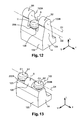
- FIGS 11 to 14 thus represent, without limitation, different variants of joint means 106, 122 comprising pivot joint means and ball joint means.
- the first hinge means 106 are constituted by at least one ball joint and the second hinge means 122 consist of at least two pivots 122A and 122B.
- the second articulation means 122 consist of first and second pivots, respectively 122A and 122B, so that the second axis of rotation 02 of the second fork 90 is a pivot axis determined by said pivots which, substantially transverse, is orthogonal to the longitudinal axis X of rotation.
- the first articulation means 106 carrying the internal articulating surface S are aligned longitudinally with the second articulation means 122 carrying the external articulation surfaces S1, S2 so that, with respect to the X axis longitudinal axis of rotation, the spacing of the first axis 01 of rotation of the first fork 88 is equal to the spacing between the second axis of rotation 02 of the second fork 90.
- the first axis of rotation O1 of the first fork 88 is coaxial with the second axis of rotation 02 of the second fork 90 so that the axes of rotation O1, O2 are merged and that the first and second forks 88, 90 have a common axis of rotation O.
- the first articulation means 106 carrying the internal articulating surface S are offset longitudinally and vertically with respect to the second articulation means 122 carrying the external articulation surfaces S1, S2 so that, with respect to the axis Longitudinal axis of rotation, the spacing of the first axis O1 of rotation of the first fork 88 is different from the center distance of the second axis of rotation 02 of the second fork 90.
- first axis of rotation O1 of the first fork 88 and the second axis of rotation 02 of the second fork 90 are at least vertically offset relative to each other so that the first and second forks 88, 90 have parallel axes of rotation 01, 02.
- the first hinge means 106 are constituted by an internal or central pivot 106 and the second hinge means 122 consist of a first ball 222A and a second ball 222B.
- the articulation means 106, 122 are, in comparison with the figure 13 , offset vertically between them so that the axes O1 and O2 are not included in a plane which is parallel to the axis X.
Description
La présente invention concerne un mécanisme à double embrayage comportant un dispositif de commande à double fourchette.The present invention relates to a dual clutch mechanism having a dual fork control device.
La présente invention concerne plus particulièrement un mécanisme à double embrayage selon le préambule de la revendication 1.The present invention more particularly relates to a double clutch mechanism according to the preamble of
Un tel mécanisme à double embrayage est notamment utilisé pour coupler alternativement l'arbre d'un moteur du véhicule avec deux arbres coaxiaux d'entrée d'une boîte de vitesses, dite boîte de vitesses à double embrayage.Such a dual clutch mechanism is used in particular to alternately couple the shaft of a vehicle engine with two coaxial input shafts of a gearbox, said double clutch gearbox.
Le mécanisme à double embrayage, encore appelé double embrayage, permet de changer de rapport de vitesses tout en maintenant la transmission d'un couple moteur aux roues du véhicule.The double-clutch mechanism, also known as a double clutch, makes it possible to change gears while maintaining the transmission of engine torque to the wheels of the vehicle.
Pour ce faire, le mécanisme à double embrayage comprend généralement un premier embrayage et un deuxième embrayage respectivement associés à des rapports de vitesses pairs et impairs.To do this, the double clutch mechanism generally comprises a first clutch and a second clutch respectively associated with even and odd gear ratios.
Lors d'un changement de rapport de vitesses, le premier embrayage est débrayé alors que le second embrayage est embrayé si bien que le couple moteur est transféré progressivement du premier embrayage au deuxième embrayage.During a change of gear ratio, the first clutch is disengaged while the second clutch is engaged so that the engine torque is transferred progressively from the first clutch to the second clutch.
Ainsi, la somme des couples transmis par les premier et deuxième embrayages est toujours sensiblement égale au couple moteur.Thus, the sum of the torques transmitted by the first and second clutches is always substantially equal to the engine torque.
Le mécanisme à double embrayage comporte encore un carter fixe délimitant un volume dans lequel sont logés les deux embrayages de passage de rapports de parités différentes.The double clutch mechanism further comprises a fixed housing defining a volume in which are housed the two gearshift clutches of different ratios.
Chaque embrayage du mécanisme comporte un diaphragme destiné à coopérer avec un plateau de pression solidaire en rotation du couvercle et de l'arbre du moteur. Chaque diaphragme est déplaçable, au moyen d'une butée de commande correspondante, entre au moins une première position et une deuxième position.Each clutch mechanism includes a diaphragm for cooperating with a pressure plate integral in rotation of the cover and the motor shaft. Each diaphragm is movable, by means of a corresponding control stop, between at least a first position and a second position.
Selon le type de l'embrayage, ladite première position du diaphragme correspond à un couplage ou découplage des arbres de moteur et de boîte de vitesses et ladite deuxième position du diaphragme correspond à un découplage ou couplage de ces arbres de moteur et de boîte de vitesses.Depending on the type of the clutch, said first position of the diaphragm corresponds to a coupling or decoupling of the engine shafts and gearbox and said second position of the diaphragm corresponds to a decoupling or coupling of these shafts of engine and gearbox .
Chaque plateau de pression, sollicité par le diaphragme correspondant, est destiné à enserrer un disque de friction entre ce plateau de pression et un plateau de réaction correspondant.Each pressure plate, urged by the corresponding diaphragm, is intended to grip a friction disc between this pressure plate and a corresponding reaction plate.
De plus, chaque disque de friction est lié en rotation à un arbre correspondant de boîte de vitesses et chaque plateau de pression est solidaire en rotation d'un couvercle, généralement lié à l'arbre moteur par des moyens de liaison tels qu'un volant flexible ou un double volant amortisseur.In addition, each friction disk is rotatably connected to a corresponding gearbox shaft and each pressure plate is rotatably connected to a cover, generally connected to the drive shaft by connecting means such as a steering wheel. flexible or double damping flywheel.
Par le serrage d'un disque de friction entre les plateaux de pression et de réaction correspondants, on réalise la transmission d'un couple entre l'arbre moteur et l'arbre de boîte de vitesses associé.By clamping a friction disk between the corresponding pressure and reaction plates, transmission of a torque between the drive shaft and the associated gearbox shaft is realized.
On connaît déjà dans l'état de la technique de nombreux exemples de mécanisme à double embrayage de ce type.Numerous examples of double clutch mechanisms of this type are already known in the state of the art.
Un tel mécanisme est équipé d'un dispositif de commande associé comportant principalement des moyens d'actionnement aptes à solliciter sélectivement chacune des première et deuxième fourchettes destinées à actionner entre deux positions extrêmes des première et deuxième butées de commande commandant respectivement le déplacement de chacun des diaphragmes du premier et du deuxième embrayages.Such a mechanism is equipped with an associated control device mainly comprising actuating means able to selectively bias each of the first and second forks intended to actuate between two extreme positions of the first and second control stops respectively controlling the displacement of each of the diaphragms of the first and second clutches.
Le document
Dans ce document, les fourchettes du dispositif de commande sont articulées chacune autour d'une liaison à rotule respectivement fixée sur le carter du mécanisme et agencée radialement au plus près l'une de l'autre, c'est-à-dire agencée l'une en dessous de l'autre selon une orientation verticale, définie par convention comme orthogonale à l'orientation longitudinale qui est déterminée par l'axe X précité de rotation du mécanisme, lequel est également l'axe principal des butées de commande mues par les fourchettes.In this document, the ranges of the control device are articulated each around a ball joint respectively fixed to the casing of the mechanism and arranged radially closer to each other, that is to say arranged l one below the other in a vertical orientation, conventionally defined as orthogonal to the longitudinal orientation which is determined by the above-mentioned X axis of rotation of the mechanism, which is also the main axis of the control stops driven by the forks.
Le document
Les
Les
Les différentes Un mécanisme et un dispositif de commande selon les préambules des revendications 1 et 12 sont connus de
En effet, l'agencement des moyens d'articulation est parfois difficile, notamment en raison de contraintes d'implantation, seul un espace réduit étant disponible pour loger les moyens d'actionnement, les fourchettes et les moyens d'articulation associés.Indeed, the arrangement of the hinge means is sometimes difficult, in particular because of implantation constraints, only a reduced space being available to accommodate the actuating means, the forks and the associated hinge means.
De surcroît, quelles que soient les contraintes particulières d'implantation d'une application donnée, les fourchettes doivent pouvoir actionner les butées de commande avec une course suffisante pour réaliser de manière satisfaisante les opérations d'embrayage ou de débrayage pour chacun des embrayages du mécanisme.Moreover, whatever the particular constraints of implementation of a given application, the forks must be able to actuate the control stops with a sufficient stroke to satisfactorily perform the clutch or disengagement operations for each of the clutches of the mechanism .
L'invention a notamment pour but de perfectionner le dispositif de commande d'un double embrayage tout en conservant pour chacun une structure simple, un encombrement particulièrement réduit et un fonctionnement efficace.The invention is intended in particular to improve the control device of a double clutch while maintaining for each a simple structure, a particularly small footprint and efficient operation.
A cet effet, l'invention a pour objet un mécanisme à double embrayage du type décrit précédemment, caractérisé en ce que la première fourchette est logée à l'intérieur de la deuxième fourchette, lesdites première et deuxième fourchettes concentriques sont imbriquées l'une dans l'autre et sont, en position de repos, globalement coplanaires.For this purpose, the subject of the invention is a double clutch mechanism of the type described above, characterized in that the first fork is housed inside the second fork, said first and second concentric forks are nested one inside the other and are, in the rest position, globally coplanar.
Grâce à un tel agencement de la surface interne d'articulation de la première fourchette entre les surfaces externes d'articulation de la deuxième fourchette, l'implantation des fourchettes et des moyens d'articulation associés peut être réalisée dans encombrement général plus réduit, tant radialement que selon la direction longitudinale.Thanks to such an arrangement of the inner articulation surface of the first fork between the external articulation surfaces of the second fork, the implantation of the forks and the associated hinge means can be achieved in a smaller overall space, both radially than in the longitudinal direction.
Avantageusement, lesdits axes de rotation des fourchettes sont situés du même côté de l'axe X.Advantageously, said axes of rotation of the forks are located on the same side of the X axis.
Par conséquent, les axes de rotation des fourchettes sont agencés de manière que, par rapport à un plan horizontal de référence passant par l'axe longitudinal X de rotation du mécanisme, le premier axe de rotation et le deuxième axe de rotation se trouvent du même côté du plan de référence ainsi défini, c'est-à-dire selon la direction verticale orthogonale audit plan, soit au dessus, soit au dessous.Therefore, the rotation axes of the forks are arranged so that, relative to a reference horizontal plane passing through the longitudinal axis X of rotation of the mechanism, the first axis of rotation and the second axis of rotation are of the same side of the reference plane thus defined, that is to say in the vertical direction orthogonal to said plane, either above or below.
Avantageusement, les moyens d'actionnement se trouvent du même côté dudit plan de référence, c'est à dire sont regroupés d'un même côté par rapport à l'axe X. notamment situés à l'opposé des axes de rotation lorsque les fourchettes sont formées par un levier du second genre.Advantageously, the actuating means are on the same side of said reference plane, ie they are grouped together on one and the same side with respect to the axis X. In particular, located opposite the axes of rotation when the ranges are are formed by a lever of the second kind.
Par comparaison avec l'état de la technique, l'agencement des moyens d'articulation des fourchettes présente un moindre encombrement selon la direction radiale et selon la direction longitudinale ou encore, à encombrement radial équivalent, une longueur de bras de levier supérieure pour au moins l'une des fourchettes.Compared with the state of the art, the arrangement of the hinge means of the forks has a smaller footprint in the radial direction and in the longitudinal direction or, with congestion radial equivalent, an upper lever length for at least one of the forks.
Avantageusement, on simplifie également l'implantation des moyens d'articulation associés aux fourchettes par l'utilisation d'une pièce d'articulation commune aux fourchettes.Advantageously, the implantation of the hinge means associated with the forks is also simplified by the use of a hinge piece common to the forks.
De préférence, la pièce commune d'articulation est liée au carter du mécanisme à partir de la face radiale avant ou fond duquel la pièce s'étend axialement ou longitudinalement vers l'avant par l'intermédiaire d'un pied présentant une longueur déterminée.Preferably, the common hinge part is connected to the housing of the mechanism from the front radial face or bottom of which the piece extends axially or longitudinally forwards through a foot having a predetermined length.
On réduit ainsi l'encombrement général du dispositif de commande comportant les fourchettes dont l'axe de rotation, de préférence un axe de pivotement commun, porté par une telle pièce commune est susceptible d'être disposé axialement plus en avant par rapport à la face du carter de manière que la course effectuée par la butée de commande actionnée par la fourchette soit maximale et obtenue pour une course correspondante des moyens d'actionnement qui soit minimale.This reduces the overall size of the control device comprising the forks whose axis of rotation, preferably a common pivot axis, carried by such a common part is likely to be disposed axially further forward with respect to the face of the casing so that the stroke performed by the thrust actuated by the fork is maximum and obtained for a corresponding stroke of the actuating means is minimal.
Avantageusement, le fonctionnement de chacune des première et deuxième fourchettes est totalement indépendant et les fourchettes sont susceptibles d'être déplacées sélectivement par des moyens d'actionnement, cela sans aucune interaction entre l'une et l'autre desdites fourchettes, les efforts appliqués à l'une n'étant en particulier pas transmis à l'autre et réciproquement.Advantageously, the operation of each of the first and second forks is completely independent and the forks may be selectively displaced by actuating means, without any interaction between one and the other of said ranges, the forces applied to one being in particular not transmitted to the other and vice versa.
Avantageusement, dans le dispositif de commande selon l'invention, les moyens d'articulation de la première fourchette et de la deuxième fourchette sont, de manière non limitative, respectivement constitués par un pivot et/ou par une rotule.Advantageously, in the control device according to the invention, the hinge means of the first fork and the second fork are, in a non-limiting manner, respectively constituted by a pivot and / or a ball joint.
Avantageusement, les fourchettes et les moyens d'articulation selon l'invention permettent un gain d'encombrement dans les directions longitudinale (ou axiale) et radiale, tout en ayant un agencement des moyens d'actionnement associés d'un même côté de l'axe de rotation.Advantageously, the forks and the hinge means according to the invention allow a saving of space in the longitudinal (or axial) directions. and radial, while having an arrangement of the associated actuating means on the same side of the axis of rotation.
Selon d'autres caractéristiques de l'invention :
- les première et deuxième fourchettes constituent respectivement un levier d'un second genre de sorte que chaque fourchette constitue un levier dans lequel la force résistante qui lui est opposée, notamment par la butée associée, s'exerce sur une partie de d'actionnement de la fourchette qui est située entre l'axe de rotation et une partie de manoeuvre sur laquelle des moyens d'actionnement exercent une force motrice ;
- les premiers moyens d'articulation portant la surface interne d'articulation sont alignés longitudinalement avec les deuxièmes moyens d'articulation portant les surfaces externes d'articulation de manière que, par rapport à l'axe longitudinal de rotation, l'entraxe du premier axe de rotation de la première fourchette est égal à l'entraxe du deuxième axe de rotation de la deuxième fourchette ;
- les premiers moyens d'articulation portant la surface interne d'articulation sont, suivant la direction verticale qui est orthogonale à la direction longitudinale définie par l'axe de rotation, décalés par rapport aux deuxièmes moyens d'articulation portant les surfaces externes d'articulation de sorte que, par rapport audit l'axe longitudinal de rotation, l'entraxe du premier axe de rotation de la première fourchette est différent de l'entraxe du deuxième axe de rotation de la deuxième fourchette ;
- le premier axe de rotation de la première fourchette est coaxial au deuxième axe de rotation de la deuxième fourchette de sorte que les axes de rotation sont confondus et que les première et deuxième fourchettes présentent un axe de rotation commun ;
- le premier axe de rotation de la première fourchette et le deuxième axe de rotation de la deuxième fourchette sont décalés longitudinalement et/ou verticalement l'un par rapport à l'autre de sorte que les première et deuxième fourchettes présentent des axes de rotation parallèles ;
- les premiers moyens d'articulation sont constitués par au moins un pivot de sorte que le premier axe de rotation de la première fourchette est un axe de pivotement qui, d'orientation sensiblement transversale, est orthogonal à l'axe longitudinal de rotation ;
- les premiers moyens d'articulation sont constitués par au moins une rotule de sorte que la première fourchette est montée mobile en rotation autour d'un centre de rotation dont l'intersection avec un demi-plan transversal de référence, d'orientation verticale et orthogonal à l'axe longitudinal de rotation, détermine ledit premier axe de rotation de la première fourchette ;
- les deuxièmes moyens d'articulation sont constitués par au moins des premier et deuxième pivots de sorte que le deuxième axe de rotation de la deuxième fourchette est un axe de pivotement déterminé par lesdits pivots qui, d'orientation sensiblement transversale, est orthogonal à l'axe longitudinal de rotation ;
- les deuxièmes moyens d'articulation sont constitués par au moins des première et deuxième rotules de sorte que la deuxième fourchette est montée mobile en rotation autour d'un centre de rotation de chaque rotule, lesdits centres de rotation déterminant par intersection avec un demi-plan transversal de référence, d'orientation verticale et orthogonal à l'axe longitudinal de rotation, ledit deuxième axe de rotation de la deuxième fourchette ;
- les moyens d'articulation respectifs desdites première et deuxième fourchettes sont réalisés en une seule pièce de sorte que ladite pièce forme un moyen commun d'articulation pour les première et deuxième fourchettes qui est lié à un carter du mécanisme ;
- la deuxième fourchette comporte un corps annulaire sensiblement de forme ovale qui délimite circonférentiellement un espace interne à l'intérieur duquel est agencé, globalement concentriquement, la première fourchette.
- the first and second forks respectively constitute a lever of a second kind so that each fork constitutes a lever in which the resisting force which is opposed to it, in particular by the associated stop, is exerted on a part of the actuation of the fork which is located between the axis of rotation and a maneuvering part on which actuating means exert a driving force;
- the first hinge means carrying the inner hinge surface are aligned longitudinally with the second hinge means carrying the external hinge surfaces so that, relative to the longitudinal axis of rotation, the center line spacing of rotation of the first fork is equal to the center distance of the second axis of rotation of the second fork;
- the first articulation means carrying the internal articulation surface are, in the vertical direction which is orthogonal to the longitudinal direction defined by the axis of rotation, offset with respect to the second articulation means carrying the external articulation surfaces so that, with respect to said longitudinal axis of rotation, the center distance of the first axis of rotation of the first fork is different from the center distance of the second axis of rotation of the second fork;
- the first axis of rotation of the first fork is coaxial with the second axis of rotation of the second fork so that the axes of rotation coincide and the first and second forks have a common axis of rotation;
- the first axis of rotation of the first fork and the second axis of rotation of the second fork are offset longitudinally and / or vertically relative to each other so that the first and second forks have parallel axes of rotation;
- the first articulation means are constituted by at least one pivot so that the first axis of rotation of the first fork is a pivot axis which, of substantially transverse orientation, is orthogonal to the longitudinal axis of rotation;
- the first articulation means are constituted by at least one ball joint so that the first fork is rotatably mounted around a center of rotation whose intersection with a reference transverse half-plane of vertical and orthogonal orientation at the longitudinal axis of rotation, determines said first axis of rotation of the first fork;
- the second articulation means are constituted by at least first and second pivots so that the second axis of rotation of the second fork is a pivot axis determined by said pivots which, substantially transverse orientation, is orthogonal to the longitudinal axis of rotation;
- the second articulation means are constituted by at least first and second ball joints so that the second fork is mounted to rotate about a center of rotation of each ball joint, said centers of rotation determining by intersection with a half plane transverse reference, of vertical orientation and orthogonal to the longitudinal axis of rotation, said second axis of rotation of the second fork;
- the respective articulation means of said first and second forks are made in one piece so that said part forms a common articulation means for the first and second forks which is connected to a casing of the mechanism;
- the second fork comprises an annular body substantially of oval shape which circumferentially delimits an internal space inside which is arranged, globally concentrically, the first fork.
L'invention concerne encore un dispositif de commande pour un mécanisme à double embrayage, selon la revendication 12.The invention further relates to a control device for a double clutch mechanism according to
Avantageusement, la surface d'articulation de la première fourchette est destinée à coopérer avec au moins une surface interne d'articulation complémentaire des premiers moyens d'articulation et les première et deuxième surfaces d'articulation de la deuxième fourchette sont destinées à coopérer respectivement avec une première surface d'articulation et une deuxième surface d'articulation complémentaires des deuxièmes moyens d'articulation.Advantageously, the articulation surface of the first fork is intended to cooperate with at least one inner articulation surface complementary to the first articulation means and the first and second articulation surfaces of the second fork are intended to cooperate respectively with a first hinge surface and a second hinge surface complementary to the second hinge means.
D'autres caractéristiques et avantages de l'invention apparaîtront à la lecture de la description détaillée qui va suivre, pour la compréhension de laquelle on se reportera aux dessins annexés parmi lesquels :
- la
figure 1 est une vue en coupe axiale qui représente un exemple de mécanisme à double embrayage et un dispositif de commande associé selon un mode de réalisation préféré de l'invention et qui illustre chacune des fourchettes dans une position de repos pour laquelle les butées de commande et les diaphragmes sont dans une position correspondante dite position extrême arrière de débrayage ; - la
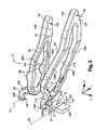
figure 2 est une vue de détail qui représente en perspective et en éclaté la première fourchette et la deuxième fourchette du dispositif de commande de lafigure 1 et leurs moyens d'articulation par pivotement autour d'un axe commun ; - la
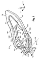
figure 3 est une vue de détail qui représente en perspective les fourchettes qui, après montage sur les moyens d'articulation et en position de repos comme illustrée sur lafigure 1 , sont sensiblement coplanaires selon la direction radiale ; - la
figure 4 est une vue similaire à celle de lafigure 1 qui représente le mécanisme dans la position dans laquelle il se trouve après le déplacement vers l'avant de la première fourchette par les premiers moyens d'actionnement et qui illustre la première fourchette dans une position de travail pour laquelle la première butée de commande et les doigts du premier diaphragme sont dans une position extrême avant d'embrayage, la deuxième butée et les doigts du deuxième diaphragme étant demeurés dans leur position extrême arrière de débrayage ; - la
figure 5 est une vue similaire à celle de lafigure 1 qui représente le mécanisme dans la position dans laquelle il se trouve après le déplacement vers l'avant de la deuxième fourchette par les deuxièmes moyens d'actionnement et qui illustre la deuxième fourchette dans une position de travail pour laquelle la deuxième butée de commande et les doigts du deuxième diaphragme sont dans une position extrême avant d'embrayage, la première butée et les doigts du premier diaphragme étant demeurés dans leur position extrême arrière de débrayage ; - la
figure 6 est une vue de détail en perspective qui représente les moyens d'articulation à pivot des première et deuxième fourchettes selon un mode de réalisation préféré du dispositif de commande et qui illustre la surface interne d'articulation de la première fourchette agencée transversalement entre les deux surfaces externes d'articulation de la deuxième fourchette ; - les
figures 7 et8 sont des vues de détail en perspective qui représentent des variantes de réalisation des moyens d'articulation à pivot des fourchettes ; - les
figures 9 et10 sont des vues de détail en perspective qui représentent un autre mode de réalisation des moyens d'articulation des première et deuxième fourchettes dans lequel lesdits moyens sont constitués par des rotules et une variante de réalisation ; - les
figures 11 à 14 sont des vues de détail en perspective qui représentent d'autres variantes de réalisation combinant des moyens d'articulation à pivot et à rotule pour les première et deuxième fourchettes.
- the
figure 1 is an axial sectional view which shows an example of a double clutch mechanism and an associated control device according to a preferred embodiment of the invention and which illustrates each of the forks in a rest position for which the control stops and the diaphragms are in a corresponding position said rearmost position of disengagement; - the
figure 2 is a detail view that represents in perspective and exploded the first fork and the second fork of the control device of thefigure 1 and their articulation means by pivoting about a common axis; - the
figure 3 is a detail view which represents in perspective the forks which, after mounting on the articulation means and in the rest position as illustrated on thefigure 1 are substantially coplanar in the radial direction; - the
figure 4 is a view similar to that of thefigure 1 which represents the mechanism in the position in which it is after the forward movement of the first fork by the first actuating means and which illustrates the first fork in a working position for which the first control stop and the fingers of the first diaphragm are in an extreme position before clutching, the second stop and the fingers of the second diaphragm having remained in their extreme rear declutching position; - the
figure 5 is a view similar to that of thefigure 1 which represents the mechanism in the position in which it is located after the forward motion of the second fork by the second actuating means and which illustrates the second fork in a working position for which the second control stop and the fingers of the second diaphragm are in an extreme position before the clutch, the first stop and the fingers of the first diaphragm having remained in their extreme rear declutching position; - the
figure 6 is a detailed perspective view showing the pivot articulation means of the first and second forks according to a preferred embodiment of the control device and which illustrates the inner articulation surface of the first fork arranged transversely between the two surfaces external articulation of the second fork; - the
figures 7 and8 are detail perspective views which represent alternative embodiments of pivot pivot means of the forks; - the
figures 9 and10 are perspective detail views which represent another embodiment of the articulation means of the first and second forks wherein said means are constituted by ball joints and an alternative embodiment; - the
Figures 11 to 14 are perspective detail views which show other alternative embodiments combining pivot and ball joint means for the first and second forks.
Dans la description et les revendications, on utilisera à titre non limitatif et afin d'en faciliter la compréhension, les termes comme "avant" et "arrière", "supérieur" et "inférieur", "externe" et "interne" selon les définitions données dans la description et déterminées par rapport aux orientations longitudinale, verticale et transversale du trièdre (L, V, T) représenté sur les figures.In the description and the claims, the terms "forward" and "backward", "upper" and "lower", "external" and "internal" will be used in a nonlimiting manner and in order to facilitate understanding thereof. definitions given in the description and determined in relation to the longitudinal, vertical and transverse trihedron (L, V, T) shown in the figures.
Par convention, les termes "avant" et "arrière" correspondent respectivement à la gauche et à la droite de la
Par convention, les termes "supérieur" et "inférieur" correspondent respectivement au haut et au bas de la
Par convention et en référence au trièdre (L, V, T), on détermine également une direction générale "axiale" suivant l'axe longitudinal X et une direction "radiale" qui, orthogonale à ladite direction axiale, désigne des éléments s'étendant globalement suivant un plan (V, T) vertical d'orientation transversale.By convention and with reference to the trihedron (L, V, T), an "axial" axial direction is also determined along the longitudinal axis X and a "radial" direction which, orthogonal to said axial direction, designates elements extending overall in a vertical plane (V, T) of transverse orientation.
L'orientation verticale n'est nullement donnée en référence à la gravité terrestre.Vertical orientation is not given in reference to Earth's gravity.
Dans la description qui va suivre, des éléments identiques, analogues ou similaires seront désignés par des mêmes numéros de référence.In the following description, identical, analogous or similar elements will be designated by the same reference numbers.
On a représenté sur la
Le mécanisme à double embrayage 10 comporte un dispositif de commande 12 associé comportant au moins une double fourchette, plus particulièrement illustrée en détail aux
Le mécanisme à double embrayage 10 est logé, avec au moins une partie du dispositif de commande 12, à l'intérieur d'un volume délimité par un carter 14.The double
Le mécanisme 10 à double embrayage est destiné à accoupler temporairement un arbre moteur (non représenté) qui est usuellement agencé longitudinalement en avant du mécanisme 10, ici à gauche de la
L'arbre moteur constitue un arbre menant qui est destiné à être entraîné en rotation par un moteur (non représenté) du véhicule automobile.The motor shaft constitutes a drive shaft which is intended to be rotated by a motor (not shown) of the motor vehicle.
Les deux arbres menés 16A et 16B du mécanisme 10 sont concentriques et sont montés rotatifs coaxialement à l'arbre moteur, le premier arbre mené 16A forme un tube à l'intérieur duquel est agencé le deuxième arbre mené 16B.The two driven
Une portion d'extrémité avant libre du deuxième arbre mené 16B s'étend longitudinalement au-delà de l'extrémité avant du premier arbre mené 16A, chacun desdits arbres menés 16A et 16B étant susceptibles de tourner indépendamment de l'autre.A free front end portion of the second driven
Les arbres menés 16A et 16B sont destinés à être reliés à une boîte de vitesses (non représentée) agencée longitudinalement à l'arrière, c'est-à-dire ici à droite de la
Plus particulièrement, le premier arbre mené 16A correspond à certains rapports de vitesses de la boîte de vitesses, par exemple les rapports de vitesses pairs, tandis que le deuxième arbre mené 16B correspond aux autres rapports de vitesses, par exemple les rapports de vitesses impairs.More particularly, the first driven
Le mécanisme 10 à double embrayage comporte un premier embrayage E1 et un deuxième embrayage E2 destinés à accoupler temporairement l'un des arbres menés 16A, 16B à l'arbre moteur et qui sont commandés sélectivement par le dispositif de commande 12 de manière à permettre respectivement le passage de rapports de vitesses de parités différentes.The double
De manière connue, le mécanisme 10 comporte un plateau radial circulaire de réaction 18 qui est monté à rotation autour de l'axe X longitudinal de rotation, par l'intermédiaire d'un palier, constitué de préférence par un roulement à billes 20.In known manner, the
Le plateau de réaction 18 est solidaire en rotation de l'arbre moteur. A cet effet, le mécanisme 10 comporte des moyens de liaison 22 avec l'arbre moteur, lesdits moyens 22 étant agencés à une extrémité longitudinale avant du mécanisme 10 et aptes à être fixés coaxialement à l'arbre moteur.The
Selon les applications, de tels moyens de liaison sont par exemple constitués par un disque radial circulaire flexible 22. En variante, les moyens de liaison 22 assurent également une fonction d'amortissement et/ou filtration et sont par exemple constitués par un double volant amortisseur.According to the applications, such connecting means are for example constituted by a flexible circular
Le premier embrayage E1 du mécanisme 10 forme des premiers moyens d'accouplement temporaire du premier arbre mené 16A avec l'arbre moteur.The first clutch E1 of the
Le premier embrayage E1 comporte un premier plateau annulaire de pression 24 qui est monté solidaire en rotation du plateau de réaction 18 autour de l'axe X de rotation.The first clutch E1 comprises a first
Le premier plateau de pression 24 est plus particulièrement agencé axialement en vis-à-vis d'une face arrière 26 du plateau de réaction 18.The
Le premier plateau de pression 24 est monté coulissant axialement par rapport au plateau de réaction 18. A cet effet, le premier plateau de pression 24 est monté coulissant axialement sur des colonnettes 28 axiales qui sont fixées à la périphérie du plateau de réaction 18.The
Le premier embrayage E1 comporte un premier disque coaxial de friction 30 qui est interposé axialement entre le plateau de réaction 18 et le premier plateau de pression 24. Le premier disque de friction 30 comporte sur ses deux faces une garniture annulaire de friction 32 qui est agencée axialement en vis-à-vis du premier plateau de pression 24 et du plateau de réaction 18.The first clutch E1 comprises a first
Le premier disque de friction 30 est destiné à être serré contre la face arrière 26 du plateau de réaction 18 par le premier plateau de pression 24 pour accoupler temporairement le premier arbre mené 16A avec l'arbre moteur.The
A cet effet, le premier disque de friction 30 est monté solidaire en rotation du premier arbre mené 16A, et il est monté coulissant axialement sur le premier arbre mené 16A tubulaire entre une position avant serrée (
Le jeu axial existant entre le premier disque de friction 30 dans sa position arrière libre et la face arrière 26 du plateau de réaction 18 est très faible de sorte que, par facilité, il n'a pas été représenté à la
Le premier embrayage E1 comporte un premier diaphragme 34 annulaire coaxial arrière d'actionnement du premier plateau de pression 24.The first clutch E1 comprises a first rear coaxial
Le premier diaphragme 34 comporte un anneau 35 radialement extérieur et des doigts 36 élastiques s'étendant radialement vers l'axe X de rotation depuis l'anneau 35 jusqu'à une extrémité intérieure libre 38. Tous les doigts 36 du premier diaphragme 34 sont de préférence identiques.The
Plus particulièrement, le premier plateau de pression 24 est interposé entre le plateau de réaction 18 et le premier diaphragme 34.More particularly, the
Le premier diaphragme 34 prend appui sur un premier couvercle annulaire 40 agencé axialement en arrière, ledit premier couvercle 40 étant fixé radialement à l'extérieur au plateau de réaction 18.The
Le premier couvercle arrière 40 comporte plus particulièrement un fond 42 radial annulaire et une jupe 44 axiale cylindrique qui s'étend vers l'avant depuis la périphérie extérieure du fond 42 jusqu'à la portion périphérique du plateau de réaction 18, en entourant le premier plateau de pression 24.The first rear cover 40 more particularly comprises an annular radial bottom 42 and a cylindrical
De préférence, le fond 42 annulaire comporte une nervure formée par un pli annulaire qui est coaxial à l'axe X de rotation et qui s'étend axialement vers l'arrière de manière à présenter une arête 46 annulaire en saillie vers l'arrière.Preferably, the annular bottom 42 comprises a rib formed by an annular fold which is coaxial with the axis of rotation X and which extends axially rearwardly so as to have an
L'anneau 35 du premier diaphragme 34 est par exemple fixé sur une face avant du fond 42 du premier couvercle 40 par l'intermédiaire d'une bride 47 comportant des pattes qui s'étendent radialement vers l'intérieur. La bride 47 est fixée au premier couvercle 40 par des rivets 48 de manière que l'anneau 35 du premier diaphragme 34 soit serré axialement contre le fond 42 du premier couvercle 40 par les pattes radiales de la bride 47.The
Une portion intermédiaire de chaque doigt 36 du premier diaphragme 34 est en appui axial sur une portion annulaire 50 du premier plateau de pression 24. Les doigts 36 du premier diaphragme 34 fonctionnent ainsi à la manière d'un levier qui est en appui par son extrémité supérieure contre le premier couvercle fixe 40.An intermediate portion of each
Les doigts 36 du premier diaphragme 34 sont flexibles élastiquement, notamment l'extrémité libre 38 des doigts 36 qui est déplacée entre une position extrême avant d'embrayage représentée à la
En position extrême avant d'embrayage, le premier diaphragme 34 sollicite axialement le premier plateau de pression 24 pour serrer le premier disque de friction 30 contre le plateau de réaction 18.In the extreme forward clutching position, the
En position extrême arrière de débrayage vers laquelle les doigts 36 sont rappelés élastiquement, le premier plateau de pression 24 n'est plus sollicité axialement par le premier diaphragme 34 de manière que le premier disque de friction 30 se trouve alors dans sa position arrière libre, comme représenté à la
Ainsi, en position extrême avant d'embrayage, le premier arbre mené 16A est accouplé temporairement à l'arbre moteur, et en position extrême arrière de débrayage, le premier disque de friction 30 est écarté du plateau de réaction 18 et du premier plateau de pression 24 de manière que le premier arbre mené 16A soit découplé de l'arbre moteur.Thus, in the extreme forward clutching position, the first driven
Le mécanisme 10 à double embrayage comporte encore le deuxième embrayage E2 formant des deuxièmes moyens d'accouplement temporaire du deuxième arbre mené 16B avec l'arbre moteur.The double
Le deuxième embrayage E2 comporte un deuxième plateau de pression 52 et un deuxième disque de friction 54 dont les fonctions sont respectivement analogues à celles du premier plateau de pression 24 et du premier disque de friction 30.The second clutch E2 comprises a
Le deuxième plateau de pression 52 est monté axialement en vis-à-vis de la face avant 56 du plateau de réaction 18.The
Le deuxième plateau de pression 52 est solidaire en rotation du plateau de réaction 18 par l'intermédiaire d'un deuxième couvercle 58 qui comporte un fond 60 annulaire radial arrière et une jupe 62 axiale cylindrique qui s'étend vers l'avant jusqu'au deuxième plateau de pression 52 en entourant le premier couvercle 40. Plus particulièrement, le deuxième couvercle 58 est relié à la périphérie du deuxième plateau de pression 52.The
Le deuxième plateau de pression 52 est monté coulissant axialement par rapport au plateau de réaction 18 et le deuxième couvercle 58 forme un tiroir qui coulisse axialement.The
Le deuxième couvercle 58 est donc solidaire du deuxième plateau de pression 52 en rotation et en coulissement axial.The
Le deuxième disque coaxial de friction 54 est interposé axialement entre le plateau de réaction 18 et le deuxième plateau de pression 52. II comporte aussi sur ses deux faces une garniture annulaire de friction 64 qui est interposée axialement entre la face avant 56 du plateau de réaction 18 et le deuxième plateau de pression 52.The second
Le deuxième disque de friction 54 est destiné à être serré contre la face avant 56 du plateau de réaction 18 par le deuxième plateau de pression 52 pour accoupler temporairement le deuxième arbre mené 16B avec l'arbre moteur.The
A cet effet, le deuxième disque de friction 54 est monté solidaire en rotation du deuxième arbre mené 16B, et il est monté coulissant axialement sur la portion d'extrémité avant du deuxième arbre mené 16B entre une position arrière serrée contre la face avant 56 du plateau de réaction 18 et une position avant libre vers laquelle il est rappelé élastiquement et dans laquelle le deuxième disque de friction 54 est éloigné de la face avant 56 du plateau de réaction 18.For this purpose, the
Comme pour le premier disque de friction 52, le jeu axial très faible existant, en position arrière libre, entre le deuxième disque de friction 54 et la face avant 56 du plateau de réaction 18 n'a pas été représenté à la
Le deuxième embrayage E2 comporte un deuxième diaphragme 66 annulaire coaxial arrière d'actionnement du deuxième plateau de pression 52. Le deuxième diaphragme 66 présente une structure analogue à celle du premier diaphragme 34.The second clutch E2 comprises a second rear axial
Le deuxième diaphragme 66 est agencé axialement en arrière du premier diaphragme 34. II est interposé axialement entre l'arête 46 du premier couvercle 40 et une face avant du fond 60 du deuxième couvercle 58. Plus particulièrement, l'anneau 67 du deuxième diaphragme 66 est agencé en appui axial contre une face avant du fond 60 du deuxième couvercle 58.The
Une portion intermédiaire des doigts 68 du deuxième diaphragme 66 prend appui axialement vers l'arrière sur l'arête 46 du premier couvercle 40.An intermediate portion of the
Le deuxième diaphragme 66 est par exemple maintenu en position par des rivets (non représentés) qui sont fixés au premier couvercle 40. Les rivets sont alors agencés entre deux doigts 68 consécutifs du deuxième diaphragme 66 avec un jeu axial. Ainsi, le deuxième diaphragme 66 est maintenu en position tout en permettant le fléchissement des doigts 68.The
Les doigts 68 du deuxième diaphragme 66 fonctionnent à la manière d'un levier. Ainsi, un effort axial d'actionnement qui est appliqué vers l'avant à l'extrémité libre 70 des doigts 68 est transmis au couvercle 34, les doigts 68 prenant appui sur l'arête 46 du premier couvercle 34, puis au plateau central 18.The
Les doigts 68 du deuxième diaphragme 66 sont flexibles élastiquement entre une position extrême avant d'embrayage qui est représentée à la
En position extrême avant d'embrayage (
Le mécanisme 10 comporte encore le dispositif de commande 12 associé qui est destiné à commander indépendamment, d'une part, le premier diaphragme 34 du premier embrayage E1 entre les positions extrêmes avant d'embrayage et arrière de débrayage et, d'autre part, le deuxième diaphragme 66 du deuxième embrayage E2 entre les positions extrêmes avant d'embrayage et arrière de débrayage.The
A cet effet, le dispositif de commande 12 comporte une première butée 72 annulaire d'actionnement du premier diaphragme 34 qui est montée coulissante axialement entre une position extrême avant d'embrayage, comme illustrée à la
Le dispositif de commande 12 comporte également une deuxième butée 74 annulaire d'actionnement du deuxième diaphragme 66 qui est montée coulissante axialement entre une position extrême avant d'embrayage dans laquelle la butée 74 sollicite axialement vers l'avant l'extrémité libre 70 des doigts 68 du deuxième diaphragme 66 dans leur position extrême avant d'embrayage, comme illustrée à la
Les première et deuxième butées 72, 74 d'actionnement sont fixées respectivement sur un premier et un deuxième manchons 76, 78 axiaux coulissants.The first and second stops 72, 74 for actuation are respectively fixed on a first and a
Les manchons 76, 78 sont montés coulissants sur un guide tubulaire 80 présentant, en coupe axiale, globalement une forme en « L ».The
Plus précisément, les manchons 76, 78 sont montés sur une partie axiale tubulaire du guide 80 qui s'étend vers l'avant depuis une autre partie radiale formant une collerette de fixation s'étendant radialement vers l'extérieur.More specifically, the
Le guide 80 est fixé par l'intermédiaire de la partie formant la collerette radiale à une face avant 82 du carter 14, par exemple par des rivets 81.The
De préférence, le premier manchon 76 est monté coulissant à l'intérieur du guide tubulaire 80 contre une face cylindrique intérieure 84 du guide 80, tandis que le deuxième manchon 78 est monté coulissant à l'extérieur du guide tubulaire 80 sur une face cylindrique extérieure 86 du guide 80.Preferably, the
En variante non représentée, le premier manchon 76 est monté coulissant autour du guide tubulaire 80 contre la face cylindrique extérieure 86 du guide 80 et le deuxième manchon 78 est monté autour du premier manchon 76 de manière que le deuxième manchon 78 coulisse axialement sur la face cylindrique extérieure du premier manchon 76. Le premier manchon 76 est alors interposé radialement entre le guide 80 et le deuxième manchon 78.In a variant not shown, the
Chaque butée 72, 74 est susceptible d'être commandée en coulissement par l'intermédiaire d'une fourchette associée, respectivement une première fourchette 88 et une deuxième fourchette 90, qui sont d'orientation globalement radiale.Each
On décrira maintenant en détails un mode de réalisation préféré de la première fourchette 88 et de la deuxième fourchette 90 et des moyens d'articulation associés selon l'invention, tels que plus particulièrement représentés aux
La première fourchette 88 comporte un corps 92 de forme globalement ovale et qui comporte respectivement, de l'extérieur vers l'intérieur selon la direction radiale, une partie de manoeuvre 94, une partie d'actionnement 96 et une partie d'articulation 98.The
La partie de manoeuvre 94 de la première fourchette 88 est destinée à coopérer avec des premiers moyens d'actionnement 100 aptes à exercer sélectivement sur ladite partie 94 un effort d'actionnement F1 déterminé propre à provoquer le déplacement de la première fourchette 88 depuis une position arrière de repos (
Le corps 92 de la première fourchette 88 se divise ensuite en deux branches 92A, 92B comportant chacune un renflement qui forme la partie d'actionnement 96 destinée à coopérer avec le premier manchon 76 de commande du coulissement de la première butée 72 sur le guide 80.The
Les deux branches 92A et 92B délimitent transversalement, avec la partie d'actionnement 94 et avec la partie d'articulation 98 agencées à chaque extrémité verticale desdites branches 92A, 92B de la première fourchette 88, une ouverture centrale 102 destinée à être traversée longitudinalement par les moyens d'actionnement des butées 72, 74, notamment les manchons 76, 78 et le guide 80.The two
Les branches 92A, 92B du corps 92 se rejoignent ensuite pour former la partie d'articulation 98 de la première fourchette 88.The
De préférence, la partie d'articulation 98 est conformée en un doigt courbe présentant, d'une part, une portion rectiligne 198 qui s'étend longitudinalement en saillie par rapport au plan radial principal du corps 92 et, d'autre part, une portion 298 qui, s'étendant verticalement, est reliée à la portion 198 à la faveur d'un coude sensiblement à angle droit.Preferably, the
La partie d'articulation 98 comporte une surface d'articulation 104, ici ménagée dans la face verticale arrière de la portion 298, qui est destinée à coopérer avec des premiers moyens d'articulation 106 de la première fourchette 88 montée mobile autour d'un premier axe de rotation 01.The
Les premiers moyens d'articulation 106 comportent au moins une surface d'articulation S, dite interne, qui est complémentaire de la surface d'articulation 104 portée par la partie d'articulation 98 de la première fourchette 88.The first articulation means 106 comprise at least one so-called internal articulation surface S which is complementary to the
La deuxième fourchette 90 comporte un corps 108 qui, également de forme globalement ovale, comporte respectivement, de l'extérieur vers l'intérieur selon la direction radiale, une partie de manoeuvre 110, une partie d'actionnement 112 et une partie d'articulation 114.The
La partie de manoeuvre 110 de la deuxième fourchette 90 est destinée à coopérer avec des deuxièmes moyens d'actionnement 116 aptes à exercer sélectivement sur ladite partie 110 un effort d'actionnement F2 déterminé propre à provoquer le déplacement de la deuxième fourchette 90 depuis une position arrière de repos (
Le corps 108 de la deuxième fourchette 90 se divise ensuite en deux branches 108A, 108B comportant chacune un méplat qui forme la partie d'actionnement 112 destinée à coopérer avec le deuxième manchon 78 de commande du coulissement de la deuxième butée 74 sur le guide 80.The
Les deux branches 108A et 108B délimitent transversalement avec la partie d'actionnement 112 et la partie d'articulation 114 à chaque extrémité verticale de la deuxième fourchette 90, une ouverture centrale 118 destinée à être traversée longitudinalement par les moyens d'actionnement des butées 72, 74, notamment les manchons 76, 78 et le guide 80.The two
Avantageusement, l'ouverture centrale 118 de la deuxième fourchette 90 détermine un espace interne à l'intérieur duquel est agencé, globalement concentriquement, la première fourchette 88.Advantageously, the
La partie d'articulation 114 comporte respectivement deux bras 114A et 114B qui, d'orientation verticale, prolongent les branches 108A et 108B comportant les méplats formant la partie d'actionnement 112 de la deuxième fourchette 90.The
Chaque bras 114A, 114B comporte sur une face radiale arrière une surface d'articulation, respectivement 120A et 120B, destinée à coopérer avec des deuxièmes moyens d'articulation de la deuxième fourchette 90 qui est montée mobile autour d'un deuxième axe de rotation 02.Each
Comme on peut le voir sur la
Avantageusement, la première fourchette 88 et la deuxième fourchette 90 sont conformées pour fonctionner sans interaction l'une avec l'autre de sorte que, lors du déplacement autour des deuxièmes moyens d'articulation 122 associés, la deuxième fourchette 90 n'entre pas en contact avec la première fourchette 88 et réciproquement.Advantageously, the
Les deuxièmes moyens d'articulation 122 comportent respectivement une première surface d'articulation S1 complémentaire de la surface d'articulation 120A du bras 114A de la deuxième fourchette 90 et une deuxième surface d'articulation S2 complémentaire de la surface d'articulation 120B du bras 114B de la deuxième fourchette 90, lesdites surfaces d'articulation S1 et S2 des deuxièmes moyens d'articulation 122 sont dites externes par comparaison à la surface interne d'articulation S de la première fourchette 88.The second articulation means 122 respectively comprise a first articulation surface S1 complementary to the
En effet, selon une caractéristique importante de l'invention, la surface interne d'articulation S de la première fourchette 88 est agencée entre lesdites première et deuxième surfaces externes d'articulation S1 et S2 de la deuxième fourchette 90.Indeed, according to an important feature of the invention, the inner articulation surface S of the
Avantageusement, la surface interne S est donc agencée transversalement entre les surfaces externes S1 et S2, lesdites surfaces d'articulation S, S1 et S2 étant juxtaposées les unes à côté des autres de manière à obtenir un agencement particulièrement compact et de faible encombrement et cela dans l'ensemble des orientations du trièdre (L, V, T).Advantageously, the inner surface S is thus arranged transversely between the outer surfaces S1 and S2, said articulation surfaces S, S1 and S2 are juxtaposed next to each other so as to obtain a particularly compact and compact arrangement and this in all the orientations of the trihedron (L, V, T).
Ainsi, les parties d'articulation 98 et 114 des première et deuxième fourchettes 88 et 90 s'interpénètrent de manière que la partie d'articulation 98 soit globalement comprise transversalement entre les bras 114A et 114B.Thus, the
Chacune des fourchettes 88, 90 constitue un levier dit du second genre, c'est-à-dire par définition un levier dans lequel la force résistante s'exerce entre l'axe de rotation et la force motrice, à titre d'exemple on rappellera qu'un casse-noix constitue un tel levier du second genre.Each of the
De préférence, la position arrière de repos de la première fourchette 88 et de la deuxième fourchette 90 est déterminée par des moyens de butée (non représentés) qui sont par exemple portés par la face avant 82 du carter 14 adjacent.Preferably, the rear rest position of the
De la même manière, le mécanisme 10 comporte avantageusement des moyens de butée aptes à limiter le déplacement des fourchettes 88, 90 et/ou des butées de commande 72, 74 axialement vers l'avant, au-delà d'une position déterminée, ce qui est susceptible de se produire après une usure importante des garnitures de chacun des disques de friction 30 et 54.In the same way, the
La première fourchette 88 est montée mobile sur les premiers moyens d'articulation 106 et autour d'un premier axe 01 tandis que la deuxième fourchette 90 est montée mobile sur les deuxièmes moyens d'articulation 122 et autour d'un deuxième axe 02.The
Avantageusement, les premiers moyens d'articulation 106 portant la surface interne d'articulation S sont alignés longitudinalement avec les deuxièmes moyens d'articulation 122 portant les surfaces externes d'articulation S1 et S2 de manière que l'entraxe du premier axe de rotation O1 de la première fourchette 88 est égal à l'entraxe du deuxième axe de rotation 02 de la deuxième fourchette 90, l'entraxe référencé "e" sur la
Grâce à un tel agencement des axes de rotation des fourchettes avec un même entraxe "e", on améliore encore les possibilités d'implantation des fourchettes 88, 90 du dispositif de commande 12 du mécanisme 10 qui présentent une compacité accrue.Thanks to such an arrangement of the axes of rotation of the forks with the same spacing "e", it further improves the possibilities of implementation of the
En effet, l'implantation des fourchettes 88 et 90 peut être réalisée dans encombrement général plus réduit qu'auparavant, notamment avec un moindre encombrement selon la direction radiale par comparaison avec l'état de la technique.Indeed, the implantation of the
Toujours par comparaison avec l'état de la technique, un tel agencement des axes des fourchettes 88 et 90 permet encore, à encombrement équivalent, d'obtenir une longueur de bras de levier supérieure pour au moins l'une des fourchettes de sorte que l'on améliore l'efficacité du dispositif de commande 12.Again in comparison with the state of the art, such an arrangement of the axes of the
Avantageusement, les axes de rotation O1 et O2 des fourchettes sont situés du même côté de l'axe X longitudinal de rotation, grâce à quoi les première et deuxième fourchettes 88 et 90 s'étendent du même côté de l'axe X avec un bras de levier optimal.Advantageously, the axes of rotation O1 and O2 of the forks are located on the same side of the longitudinal axis X of rotation, whereby the first and
Avantageusement, les moyens d'actionnement 100 et 116 respectivement associés aux fourchettes 88 et 90 sont situés du même côté de l'axe X longitudinal de rotation.Advantageously, the actuating means 100 and 116 respectively associated with the
Grâce à quoi, on obtient un dispositif de commande 12 particulièrement peu encombrant et ceci sans sacrifier aux performances dudit dispositif en général et des fourchettes 88 et 90 en particulier.With this, we obtain a
Comme on peut le voir sur les figures, on entend par situés du même côté de l'axe X longitudinal de rotation, le fait que les axes de rotation O1 et 02 des fourchettes 88 et 90 sont disposés de manière que, par rapport à un plan horizontal de référence passant par l'axe longitudinal X de rotation du mécanisme, le premier axe de rotation O1 et le deuxième axe de rotation 02 se trouvent du même côté du plan de référence ainsi défini.As can be seen in the figures, it is understood that located on the same side of the longitudinal axis of rotation X, the fact that the axes of rotation O1 and O2 of the
Autrement dit, les points d'intersection des axes de rotation 01, 02 et d'un plan de référence d'orientation verticale passant par ledit axe X longitudinal de rotation sont situés dans un même demi-plan vertical.In other words, the points of intersection of the axes of
Avantageusement, les première et deuxième fourchettes 88 et 90 s'étendent radialement dans un même plan et sont, en position de repos, globalement coplanaires.Advantageously, the first and
Avantageusement, les première et deuxième fourchettes 88 et 90 sont concentriques, la première fourchette 88 étant logée à l'intérieur de la deuxième fourchette 90.Advantageously, the first and
Grâce à une telle conformation des première et deuxième fourchettes 88 et 90 imbriquées l'une dans l'autre telles des éléments cigognes, on obtient un sous-ensemble particulièrement compact et cela tant axialement que transversalement dès lors que les fourchettes 88 et 90 ne sont pas décalées angulairement l'une par rapport à l'autre autour de l'axe X mais s'étendent verticalement suivant une même direction radiale rectiligne, orthogonale à l'axe X.Thanks to such a conformation of the first and
Le premier axe de rotation 01 et le deuxième axe de rotation 02 sont plus particulièrement représentés à la
Selon le mode de réalisation préféré représenté sur les figures, le premier axe de rotation O1 de la première fourchette 88 est coaxial au deuxième axe de rotation 02 de la deuxième fourchette 90 de sorte que les axes de rotation O1, 02 sont confondus.According to the preferred embodiment shown in the figures, the first axis of rotation O1 of the
Avantageusement, les première et deuxième fourchettes 88, 90 présentent donc un axe commun de rotation O qui est par conséquent le seul axe de rotation représenté sur certaines des figures dès lors que, porté par les moyens d'articulation, l'axe commun O constitue l'axe de rotation 01 et l'axe de rotation 02 respectivement.Advantageously, the first and
Selon ce mode de réalisation préféré représenté sur les figures, les premiers moyens d'articulation 106 sont constitués par un premier pivot 106 de sorte que le premier axe de rotation 01 de la première fourchette 88, avantageusement formé par l'axe commun O, est un axe de pivotement qui, d'orientation sensiblement transversale, est orthogonal à l'axe X longitudinal de rotation.According to this preferred embodiment shown in the figures, the first articulation means 106 are constituted by a
De même, les deuxièmes moyens d'articulation 122 sont constitués par un deuxième pivot 122 de sorte que le deuxième axe de rotation 02 de la deuxième fourchette 90, également formé par l'axe commun O, est un axe de pivotement qui, d'orientation sensiblement transversale, est orthogonal à l'axe X longitudinal de rotation.Similarly, the second hinge means 122 are constituted by a
Par conséquent, dans le mode de réalisation préféré selon l'invention, la première fourchette 88 comme la deuxième fourchette 90 sont montées mobiles, entre leurs positions respectives arrière de repos et avant de travail, respectivement autour d'un premier axe 01 de pivotement porté par les premiers d'articulation 106 et d'un deuxième axe 02 de pivotement porté par les deuxièmes moyens d'articulation 122.Therefore, in the preferred embodiment according to the invention, the
Les axes O1 et 02 de pivotement sont donc constitués par un seul unique axe commun O de pivotement lequel est avantageusement porté par un moyen unique d'articulation formant à la fois les premiers moyens d'articulation 106 de la première fourchette 88 et les deuxièmes moyens d'articulation 122 de la deuxième fourchette 90.The axes O1 and O2 of pivoting are therefore constituted by a single single common axis O of pivoting which is advantageously carried by a single hinge means forming both the first hinge means 106 of the
En variante non représentée, les premiers moyens d'articulation 106 de la première fourchette 88 et les deuxièmes moyens d'articulation 122 de la deuxième fourchette 90 sont distincts et constitués par au moins deux pivots agencés transversalement l'un à côté de l'autre pour présenter un même axe O de pivotement.In variant not shown, the first hinge means 106 of the
Les moyens d'articulation 106, 122 respectifs desdites première et deuxième fourchettes 88, 90 sont ainsi avantageusement réalisés en une seule pièce qui est de préférence liée au carter 14 de sorte que ladite pièce forme un moyen commun d'articulation pour les première et deuxième fourchettes 88, 90.The respective hinge means 106, 122 of said first and
Grâce à une telle réalisation des moyens d'articulation, on simplifie également tant la fabrication que l'implantation des moyens d'articulation 106-122.Thanks to such an embodiment of the articulation means, it also simplifies both the manufacture and the implementation of the hinge means 106-122.
Pour réaliser l'articulation pivotante, ladite pièce formant un pivot commun des première et deuxième fourchettes 88, 90 comporte une surface d'articulation 124 unique formant respectivement la surface interne d'articulation S et les première et deuxième surfaces externes d'articulation S1 et S2, ladite surface 124 étant donc complémentaire des surfaces d'articulation respectives 104 et 120A, 120B des parties d'articulation 98 et 114 des première et deuxième fourchettes 88, 90.To achieve the pivot joint, said piece forming a common pivot of the first and
De préférence et comme illustré en détail à la
Avantageusement, le pied 125 du pivot commun 106-122 est solidaire du carter 14 et le pivot est réalisé venu de matière, en une seule pièce, avec le carter 14.Advantageously, the
En variante, le pivot commun 106-122 est une pièce distincte qui est rapportée à fixation sur la face 82 du carter par tous moyens appropriés, par exemple par soudage.In a variant, the common pivot 106-122 is a separate part which is attached to the
Les surfaces d'articulation respectives 104 et 120A, 120B des première et deuxième fourchettes 88, 90 d'une part, et la surface unique d'articulation 124 du pivot commun d'autre part, sont destinées à coopérer ensemble pour former une articulation pivotante autour de l'axe commun O et lesdites surfaces sont constituées par des surfaces cylindriques, ici de section globalement circulaire.The respective hinge surfaces 104 and 120A, 120B of the first and
Avantageusement, les surfaces d'articulation respectives 104 et 120A, 120B des parties d'articulation 98 et 114 des première et deuxième fourchettes 88, 90 sont usinées simultanément lors d'une même opération.Advantageously, the respective hinge surfaces 104 and 120A, 120B of the
De même, lorsque l'axe de rotation des fourchettes est un axe commun O de pivotement, on en réduit encore les coûts grâce à une unique opération d'usinage de la tête 123 du pivot commun 106-122 pour réaliser la surface unique d'articulation 124 formant les surfaces d'articulation S et S1, S2 de chacune des fourchettes 88 et 90 respectivement.Likewise, when the axis of rotation of the forks is a common axis O of pivoting, the costs are further reduced by a single machining operation of the
Avantageusement, le pivot commun 106-122 formant les moyens d'articulation des fourchettes 88 et 90 est lié au carter 14 par l'intermédiaire de son pied 125 qui s'étend axialement vers l'avant, ici de manière rectiligne, à partir de la face 82 formant le fond du carter 14 du mécanisme 10.Advantageously, the common pivot 106-122 forming the hinge means of the
De préférence, l'axe commun O de pivotement des fourchettes 88 et 90 est porté par le pivot commun 106-122, lequel pivot commun est susceptible d'être, par comparaison avec l'état de la technique, disposé axialement plus en avant par rapport à la face 82 du carter 14.Preferably, the common axis O of pivoting of the
Grâce à une telle implantation de l'axe O de pivotement éloignée vers l'avant de la face 82 du carter 14, la course effectuée par chaque butée de commande 72, 74 actionnée par la fourchette 88, 90 associée est maximale et obtenue pour une course correspondante des moyens d'actionnement 100 et 116 qui est avantageusement minimale.Thanks to such an implantation of the axis O of pivoting away towards the front of the
De préférence, les bras 114A et 114B sont reliés entre eux par une partie du corps 108 qui forme un pont s'étendant transversalement entre eux de manière à faciliter l'usinage de chacune des surfaces 120A et 120B.Preferably, the
Avantageusement, la deuxième fourchette 90 présente ainsi une rigidité d'ensemble, notamment dans sa partie d'articulation 114, apte à éviter également tout contact avec la première fourchette 88 qui est agencée à l'intérieur de son corps 108 et dont la partie d'articulation 98 est interposée transversalement entres les bras 114A et 114B.Advantageously, the
Avantageusement, les surfaces d'articulation 104, 120A et 120B des fourchettes 88 et 90 sont usinées simultanément en une seule opération pour une plus grande précision par rapport à la surface unique d'articulation 124 complémentaire du pivot commun 106-122.Advantageously, the articulation surfaces 104, 120A and 120B of the
Comme décrit précédemment, les
Les moyens d'actionnement 100 et 116 sont par exemple constitués par un actionneur comportant une tige d'actionnement dont l'extrémité libre avant est en contact avec une face radiale arrière, respectivement 126 et 128, que comporte chacune des parties d'actionnement 94 et 110 des première et deuxième fourchettes 88, 90.The actuating means 100 and 116 consist, for example, of an actuator comprising an actuating rod whose front free end is in contact with a rear radial face, respectively 126 and 128, which each of the
De préférence, les moyens d'actionnement 110, 116 sont constitués par un actionneur de type électromécanique.Preferably, the actuating means 110, 116 are constituted by an electromechanical type actuator.
Pour procéder à la commande du premier embrayage E1, les premiers moyens d'actionnement 100 sont commandés pour appliquer sur la face verticale arrière 126 de la première fourchette 88 un effort F1 déterminé qui provoque le pivotement de la fourchette 88 autour de l'axe commun de pivotement O de manière à déplacer la première fourchette 88 axialement vers l'avant depuis sa position arrière de repos, illustrée à la
Le déplacement de la première fourchette 88 de sa position arrière de repos vers sa position avant de travail provoque simultanément, par l'intermédiaire du premier manchon 76 qui coulisse sur le guide 80, le déplacement de la première butée de commande 72 depuis sa position extrême arrière de débrayage vers sa position extrême avant d'embrayage.The displacement of the
La première butée de commande 72 agit elle-même simultanément sur les doigts 36 du premier diaphragme 36 qui sollicite alors le premier plateau de pression 24 vers le plateau de réaction 18 afin de serrer entre eux le premier disque de friction 30 pour assurer l'accouplement du premier arbre mené 16A avec l'arbre moteur.The first control stop 72 itself acts simultaneously on the
Pour procéder à la commande du deuxième embrayage E2, les deuxièmes moyens d'actionnement 116 sont commandés pour appliquer sur la face verticale arrière 128 de la deuxième fourchette 90 un effort F2 déterminé qui provoque le pivotement de la fourchette 90 autour de l'axe commun de pivotement O de manière à déplacer la deuxième fourchette 90 axialement vers l'avant depuis sa position arrière de repos, illustrée à la
Le déplacement de la deuxième fourchette 90 de sa position arrière de repos vers sa position avant de travail provoque simultanément, par l'intermédiaire du deuxième manchon 78 qui coulisse sur le guide 80, le déplacement de la deuxième butée de commande 74 depuis sa position extrême arrière de débrayage vers sa position extrême avant d'embrayage.The displacement of the
La deuxième butée de commande 74 agit elle-même simultanément sur les doigts 68 du deuxième diaphragme 66 qui sollicite alors le deuxième plateau de pression 24, axialement vers l'arrière, en direction du plateau de réaction 18 afin de serrer entre eux le deuxième disque de friction 54 pour assurer l'accouplement du deuxième arbre mené 16B avec l'arbre moteur.The second control stop 74 itself acts simultaneously on the
Bien entendu, l'invention n'est nullement limitée au mode de réalisation préféré qui vient d'être décrit en référence aux
De nombreuses variantes de réalisation des moyens d'articulation 106, 122 des fourchettes peuvent être envisagées sans sortir du cadre de l'invention.Many alternative embodiments of hinge means 106, 122 of the ranges can be envisaged without departing from the scope of the invention.
Ainsi, on décrira ci-après de manière non limitative et en procédant par comparaison, notamment avec le mode de réalisation préféré décrit précédemment et illustré aux
Avantageusement, dans chacun des exemples ou variantes de réalisation décrites ci-après, la surface interne d'articulation S portée par les premiers moyens d'articulation 106 et associée à la première fourchette 88 est agencée transversalement entre les surfaces externes d'articulation S1 et S2.Advantageously, in each of the examples or variants of embodiment described below, the internal articulation surface S carried by the first articulation means 106 and associated with the
Plus précisément, les surfaces externes d'articulation S1 et S2 sont disposées selon l'orientation transversale de part et d'autre de la surface interne d'articulation S et cela que les surfaces S et S1, S2 soient ou non décalées longitudinalement ou verticalement entre elles.More precisely, the external articulating surfaces S1 and S2 are arranged in transverse orientation on either side of the internal articulating surface S and that the surfaces S and S1, S2 are or are not offset longitudinally or vertically. between them.
Selon une première variante représentée à la
Les premiers moyens d'articulation 106 sont ainsi constitués par au moins un pivot, dit interne, de sorte que le premier axe de rotation 01 de la première fourchette 88 est un axe de pivotement qui est d'orientation sensiblement transversale et donc orthogonal à l'axe X longitudinal de rotation.The first articulation means 106 are thus constituted by at least one so-called internal pivot, so that the first axis of
Les deuxièmes moyens d'articulation 122 sont donc également constitués par des pivots, respectivement un premier pivot 122A et un deuxième pivot 122B.The second hinge means 122 are therefore also constituted by pivots, respectively a
Le deuxième axe de rotation 02 de la deuxième fourchette 90 est un axe de pivotement qui, déterminé par lesdits pivots 122A, 122B, s'étend suivant une orientation sensiblement transversale et orthogonalement à l'axe X longitudinal de rotation.The second axis of
Les premiers moyens d'articulation 106, formés ici par le pivot interne, comportent une surface interne S pour l'articulation de la première fourchette 88, ladite surface interne S étant destinée à coopérer avec la surface d'articulation 104 complémentaire que comporte la partie d'articulation 98 de la première fourchette 88.The first articulation means 106, formed here by the internal pivot, comprise an internal surface S for the articulation of the
Les premier et deuxième pivots 122A et 122B formant les deuxièmes moyens d'articulation 122 comportent respectivement une première surface externe d'articulation S1 et une deuxième surface externe d'articulation S2 qui sont destinées à coopérer avec les surfaces d'articulation complémentaires 120A et 120B des bras 114A et 114B de la partie d'articulation 114 de la deuxième fourchette 90.The first and
Avantageusement, la surface interne d'articulation S est agencée transversalement entre lesdites première et deuxième surfaces externes d'articulation S1 et S2.Advantageously, the internal articulating surface S is arranged transversely between said first and second external articulation surfaces S1 and S2.
Par comparaison avec l'exemple de réalisation des
Ainsi, par rapport à l'axe longitudinal X de rotation, l'entraxe du premier axe de rotation 01 de la première fourchette 88 est égal à l'entraxe du deuxième axe de rotation 02 de la deuxième fourchette 90.Thus, with respect to the longitudinal axis X of rotation, the spacing of the first axis of
Les première et deuxième fourchettes 88, 90 présentent donc des axes de rotation 01 et 02 qui, tout en présentant le même entraxe "e" par rapport à l'axe X, sont parallèles et non plus confondus comme précédemment.The first and
Selon cette première variante, le premier axe de rotation 01 de la première fourchette 88 et le deuxième axe de rotation 02 de la deuxième fourchette 90 sont décalés longitudinalement l'un par rapport à l'autre de sorte que les première et deuxième fourchettes 88 et 90 présentent des axes de rotation qui sont parallèles.According to this first variant, the first axis of
Les axes de rotation 01 et 02 sont ainsi compris dans un même plan horizontal (L, T) suivant le trièdre (L, V, T) représenté à la
Avantageusement, les pivots 106, 122A et 122B formant mes moyens d'articulation respectifs desdites première et deuxième fourchettes 88 et 90 sont réalisés en une seule pièce.Advantageously, the
De préférence, ladite pièce comporte une tête 123 qui est usinée pour former les surfaces d'articulation S, S1 et S2 de chacun des pivots 106, 122A et 122B de sorte que ladite tête 123 ne présente dès lors plus une surface unique d'articulation 124 mais un profil étagé comportant différents tronçons et dans lequel la surface interne S est agencée transversalement entre les surfaces externes S1 et S2 et longitudinalement en retrait vers l'arrière par rapport auxdites surfaces S1, S2.Preferably, said piece comprises a
Par comparaison avec les
Selon l'invention, le tronçon central de surface d'articulation de la première fourchette 88 est interposé transversalement entre les tronçons de surfaces d'articulation de la deuxième fourchette 90 agencés aux extrémités et portées par les pivots 122A et 122B solidaires de la pièce commune.According to the invention, the central portion of hinge surface of the
Selon la première variante, la surface interne d'articulation S de la première fourchette 88 portée par le pivot 106 est décalée longitudinalement ou axialement vers l'arrière par rapport aux surfaces externes d'articulation S1 et S2 de la deuxième fourchette 90 portées par les pivots 122A et 122B de sorte que les axes de rotation O1 et O2 soient parallèles et non confondus.According to the first variant, the internal articulation surface S of the
En variante, la surface interne d'articulation S de la première fourchette 88 portée par le pivot 106 est décalée longitudinalement vers l'avant par rapport aux surfaces externes d'articulation S1 et S2 de la deuxième fourchette 90 portées par les pivots 122A et 122B de sorte que ladite surface interne S fasse saillie axialement vers l'avant par rapport auxdites surfaces externes S1 et S2 en retrait.As a variant, the internal articulating surface S of the
Avantageusement, ladite pièce commune forme un moyen commun d'articulation pour les première et deuxième fourchettes 88 et 90 et la tête 123 se prolonge longitudinalement par un pied 125 qui est lié à la face 82 du carter 14 du mécanisme 10.Advantageously, said common part forms a common articulation means for the first and
On décrira maintenant, par comparaison avec la première variante du mode de réalisation préféré, une deuxième variante de réalisation illustrée à la
Les moyens d'articulation 106 et 122 à pivot sont analogues à ceux décrits pour la première variante illustrée à la
Selon cette deuxième variante, la surface interne S d'articulation de la première fourchette 88 portée par le pivot 106 est non seulement décalée longitudinalement par rapport aux surfaces externes d'articulation S1 et S2 portées respectivement par les pivots 122A et 122B mais est encore décalée verticalement de sorte que les axes de rotation 01 et 02 sont parallèles mais pas compris dans un plan horizontal parallèle à l'axe X longitudinal de rotation.According to this second variant, the internal articulation surface S of the
Avantageusement, l'invention propose encore un dispositif de commande 12 pour un mécanisme 10 à double embrayage.Advantageously, the invention further proposes a
Le dispositif de commande 12 comporte au moins la première fourchette 88 et la deuxième fourchette 90 agencées dans une position de fonctionnement dans laquelle les fourchettes 88, 90 sont associées pour la commande dudit embrayage 10.The
Avantageusement, la première fourchette 88 comporte une partie d'articulation 98 comportant au moins une surface d'articulation 104 et la deuxième fourchette 90 comporte une partie d'articulation 114 formée par les bras 114A, 114B comportant une première et une deuxième surfaces d'articulation 120A et 120B, ladite surface d'articulation 104 de la première fourchette 88 étant, en position de fonctionnement, agencée transversalement entre lesdites première et deuxième surfaces d'articulation 120A, 120B de la deuxième fourchette 90.Advantageously, the
La surface d'articulation 104 de la première fourchette 88 est destinée à coopérer avec au moins une surface interne d'articulation S complémentaire des premiers moyens d'articulation 106.The
Les première et deuxième surfaces d'articulation 120A et 120B de la deuxième fourchette 90 sont destinées à coopérer respectivement avec une première surface d'articulation S1 et une deuxième surface d'articulation S2 complémentaires des deuxièmes moyens d'articulation 122.The first and second hinge surfaces 120A and 120B of the
Bien entendu, les moyens d'articulation 106, 122 des première et deuxième fourchettes 88 et 90 ne sont nullement limités à une articulation de type pivotante.Of course, the hinge means 106, 122 of the first and
Selon un autre mode de réalisation illustré plus particulièrement aux
Dans cet autre mode, les premiers moyens d'articulation 106 sont constitués par au moins une rotule centrale 206 et les deuxièmes moyens d'articulation 122 sont constitués par au moins des première et deuxième rotules, respectivement 222A et 222B.In this other mode, the first hinge means 106 are constituted by at least one
La première fourchette 88 est donc montée mobile en rotation autour d'un centre de rotation C dont l'intersection avec un demi-plan transversal de référence, d'orientation verticale et orthogonal à l'axe longitudinal de rotation X, détermine ledit premier axe de rotation O1 de la première fourchette 88.The
La deuxième fourchette 90 est montée mobile en rotation par l'intermédiaire de son bras 114A autour d'un premier centre de rotation C1 d'une première rotule 222A et par l'intermédiaire de son autre bras 114B autour d'un deuxième centre de rotation C2 d'une deuxième rotule 222B.The
Les centres de rotation C1 et C2 déterminent le deuxième axe de rotation 02 de la deuxième fourchette 90 par intersection avec le demi-plan transversal de référence qui est d'orientation verticale et orthogonal à l'axe longitudinal de rotation X.The centers of rotation C1 and C2 determine the second axis of
Les centres de rotation C, C1 et C2 des rotules 206, 222A et 222B sont alignés suivant l'orientation transversale de manière que le premier axe de rotation 01 de la première fourchette 88 passant par le centre C est coaxial au deuxième axe de rotation 02 de la deuxième fourchette 90 passant par les centres C1 et C2.The centers of rotation C, C1 and C2 of the ball joints 206, 222A and 222B are aligned in the transverse orientation so that the first axis of
Plus précisément, les axes de rotation 01, 02 sont confondus et les première et deuxième fourchettes 88, 90 présentent un axe de rotation O commun.More specifically, the axes of
Les premiers moyens d'articulation 106 formé par la rotule centrale 206 comportent au moins une surface interne S d'articulation de la première fourchette 88 et les deuxièmes moyens d'articulation 122 sont formés par les rotules externes 222A et 222B qui comportent respectivement une première surface d'articulation S1 et une deuxième surface d'articulation S2 de la deuxième fourchette 90.The first hinge means 106 formed by the
La surface interne d'articulation S de la première fourchette 88 est agencée transversalement entre lesdites première et deuxième surfaces externes S1 et S2 d'articulation de la deuxième fourchette 90.The internal hinge surface S of the
Avantageusement, la rotule 206 formant les premiers moyens d'articulation 106 et portant la surface interne d'articulation S est alignée longitudinalement avec les rotules externes 222A et 222B formant les deuxièmes moyens d'articulation 122 et portant les surfaces externes d'articulation S1, S2.Advantageously, the
Ainsi, par rapport à l'axe X longitudinal de rotation, l'entraxe du premier axe 01 de rotation de la première fourchette 88 est égal à l'entraxe du deuxième axe de rotation 02 de la deuxième fourchette 90.Thus, with respect to the longitudinal axis X of rotation, the spacing of the
De préférence, les rotules 206, 222A et 222B formant les moyens d'articulation 106, 122 des première et deuxième fourchettes 88 et 90 sont portées par une seule pièce commune comportant, à son extrémité longitudinale avant, une tête 123 portant lesdits moyens d'articulation 106, 122 et un pied 125 qui, s'étendant longitudinalement en arrière de la tête 123, est lié à la face 82 du carter 14 du mécanisme.Preferably, the ball joints 206, 222A and 222B forming the hinge means 106, 122 of the first and
La
Selon cette variante, les premiers moyens d'articulation 106 portant la surface interne d'articulation S sont décalés verticalement par rapport aux deuxièmes moyens d'articulation 122 portant les surfaces externes d'articulation S1 et S2 de sorte que, par rapport à l'axe X longitudinal de rotation, l'entraxe du premier axe 01 de rotation de la première fourchette 88 est différent de l'entraxe du deuxième axe de rotation 02 de la deuxième fourchette 90.According to this variant, the first hinge means 106 carrying the internal articulating surface S are offset vertically relative to the second hinge means 122 carrying the external hinge surfaces S1 and S2 so that, with respect to the longitudinal axis of rotation, the distance between the
Selon une variante non représentée, le premier axe de rotation 01 de la première fourchette 88 et le deuxième axe de rotation 02 de la deuxième fourchette 90 sont également décalés longitudinalement l'un par rapport à l'autre, en combinaison ou non avec le fait d'être décalés verticalement l'un par rapport à l'autre, de sorte que les première et deuxième fourchettes 88 et 90 présentent des axes de rotation 01 et 02 parallèles qui sont compris ou pas dans un même plan horizontal (L, T) selon que les moyens 106, 122 sont uniquement décalés longitudinalement ou également décalés verticalement.According to a variant not shown, the first axis of
Les axes de rotation 01 et 02 des première et deuxième fourchettes 88 et 90 sont situés du même côté de l'axe X de manière que, par rapport à un plan horizontal de référence passant par l'axe longitudinal X de rotation du mécanisme 10, le premier axe de rotation 01 et le deuxième axe de rotation 02 se trouvent du même côté dudit plan de référence.The axes of
Les première et deuxième fourchettes 88, 90 constituent comme précédemment chacune un levier d'un second genre, c'est que chaque fourchette 88, 90 constitue un levier dans lequel la force résistante qui lui est opposée, notamment par la butée 72, 74 associée, s'exerce sur une partie de d'actionnement 96, 112 de la fourchette 88, 90 qui est située entre l'axe de rotation 01, 02 et une partie de manoeuvre 94, 110 sur laquelle des moyens d'actionnement 100, 116 exercent une force motrice.The first and
Avantageusement, la deuxième fourchette 90 comporte un corps annulaire 108 sensiblement de forme ovale qui délimite circonférentiellement un espace interne 118 à l'intérieur duquel est agencé, globalement concentriquement, la première fourchette 88, seules les parties d'articulation 98 et 114 des fourchettes 88, 90 étant modifiées selon le type de moyens d'articulation 106, 122 associés.Advantageously, the
Toutefois, les modes de réalisation de l'invention ne sont également pas limités à une juxtaposition de moyens d'articulation 106, 122 qui soient du même type, c'est-à-dire soit à pivot comme illustré aux
Les
Dans les variantes de réalisation illustrées aux
La première fourchette 88 est donc montée mobile en rotation autour d'un centre de rotation C de la rotule 206 dont l'intersection avec un demi-plan transversal de référence, d'orientation verticale et orthogonal à l'axe longitudinal de rotation X, détermine le premier axe de rotation 01 de la première fourchette 88.The
Les deuxièmes moyens d'articulation 122 sont constitués par des premier et deuxième pivots, respectivement 122A et 122B, de sorte que le deuxième axe de rotation 02 de la deuxième fourchette 90 est un axe de pivotement déterminé par lesdits pivots qui, d'orientation sensiblement transversale, est orthogonal à l'axe longitudinal X de rotation.The second articulation means 122 consist of first and second pivots, respectively 122A and 122B, so that the second axis of
Avantageusement, les premiers moyens d'articulation 106 formés par la rotule 206 comportent au moins une surface interne d'articulation S de la première fourchette 88 et les deuxièmes moyens d'articulation 122 formés par les pivots 122A et 122B comportent respectivement une première surface d'articulation S1 et une deuxième surface d'articulation S2, dites externes, de la deuxième fourchette 90.Advantageously, the first articulation means 106 formed by the
Avantageusement, la surface interne d'articulation S est agencée transversalement entre lesdites première et deuxième surfaces externes d'articulation S1 et S2.Advantageously, the internal articulating surface S is arranged transversely between said first and second external articulation surfaces S1 and S2.
De préférence, les premiers moyens d'articulation 106 portant la surface interne d'articulation S sont alignés longitudinalement avec les deuxièmes moyens d'articulation 122 portant les surfaces externes d'articulation S1, S2 de manière que, par rapport à l'axe X longitudinal de rotation, l'entraxe du premier axe 01 de rotation de la première fourchette 88 est égal à l'entraxe du deuxième axe de rotation 02 de la deuxième fourchette 90.Preferably, the first articulation means 106 carrying the internal articulating surface S are aligned longitudinally with the second articulation means 122 carrying the external articulation surfaces S1, S2 so that, with respect to the X axis longitudinal axis of rotation, the spacing of the
Avantageusement, le premier axe de rotation O1 de la première fourchette 88 est coaxial au deuxième axe de rotation 02 de la deuxième fourchette 90 de sorte que les axes de rotation O1, 02 sont confondus et que les première et deuxième fourchettes 88, 90 présentent un axe de rotation O commun.Advantageously, the first axis of rotation O1 of the
Selon une variante de réalisation représentée à la
Dans la variante de la
Selon deux autres variantes de réalisation illustrées aux
Dans ces variantes, les premiers moyens d'articulation 106 étant constitués par au moins un pivot 106, le premier axe de rotation 01 de la première fourchette 88 est un axe de pivotement qui, d'orientation sensiblement transversale, est orthogonal à l'axe longitudinal de rotation X.In these variants, the first hinge means 106 being constituted by at least one
De même, les deuxièmes moyens d'articulation 122 étant constitués par les première et deuxième rotules, la deuxième fourchette 90 est montée mobile en rotation autour d'un centre de rotation C1, C2 de chaque rotule 222A, 222B, lesdits centres de rotation C1 et C2 déterminant le deuxième axe de rotation 02 de la deuxième fourchette 90 par intersection avec un demi-plan transversal de référence, d'orientation verticale et orthogonal à l'axe longitudinal de rotation X.Similarly, the second articulation means 122 being constituted by the first and second ball joints, the
Dans la variante de la
Dans la variante de la
Claims (13)
- Dual clutch mechanism (10), in particular for a motor vehicle, having a longitudinally oriented rotational axis (X) and comprising at least one associated control device (12) that comprises at least a first fork (88) and a second fork (90) mounted so as to be mobile on first articulation means (106) about a first axis (O1) and on second articulation means (122) about a second axis (02), respectively, the first articulation means (106, 206) comprising at least one articulation surface (S), designated internal, of the first fork (88) and second articulation means (122, 122A, 122B, 222A, 222B) comprising a first articulation surface (S1) and a second articulation surface (S2), designated external, of the second fork (90), said internal articulation surface (S) being arranged between said first and second external articulation surfaces (S 1, S2), characterized in that the first fork (88) is located inside the second fork (90), said first and second concentric forks (88, 90) are imbricated within one another and are, in the rest position, coplanar overall.
- Mechanism (10) according to claim 1, characterized in that the first and second forks (88, 90) respectively constitute a lever of a second type.
- Mechanism (10) according to claim 1, characterized in that the first articulation means (106, 206) supporting the internal articulation surface (S) are longitudinally aligned with the second articulation means (122, 122A, 122B, 222A, 222B) supporting the external articulation surfaces (S 1, S2) so that, relative to the longitudinal rotational axis (X), the interaxial distance of the first rotational axis (O1) of the first fork (88) is equal to the interaxial distance of the second rotational axis (02) of the second fork (90).
- Mechanism (10) according to claim 1, characterized in that the first articulation means (106, 206) supporting the internal articulation surface (S), following the vertical direction which is orthogonal to the longitudinal direction defined by the rotational axis (X), are offset relative to the second articulation means (122, 122A, 122B, 222A, 222B) supporting the external articulation surfaces (S1, S2) so that, relative to said longitudinal rotational axis (X), the interaxial distance of the first rotational axis (O1) of the first fork (88) is different from the interaxial distance of the second rotational axis (02) of the second fork (90).
- Mechanism (10) according to claim 3, characterized in that the first rotational axis (O1) of the first fork (88) is coaxial with the second rotational axis (02) of the second fork (90) so that the rotational axes (O1, O2) are merged and so that the first and second forks (88, 90) have a common rotational axis (O).
- Mechanism (10) according to any one of claims 3 or 4, characterized in that the first rotational axis (O1) of the first fork (88) and the second rotational axis (02) of the second fork (90) are longitudinally and/or vertically offset one relative to another so that the first and second forks (88, 90) have parallel rotational axes (O1, O2).
- Mechanism (10) according to claim 1, characterized in that the first articulation means (106) are constituted by at least one pivot (106) in such a way that the first rotational axis (O1) of the first fork (88) is a fulcrum pin which, of substantially transverse orientation, is orthogonal to the longitudinal rotational axis (X).
- Mechanism (10) according to claim 1, characterized in that the first articulation means (106) are constituted by at least one spherical bearing (206) in such a way that the first fork (88) mounted so as to be mobile about a centre of rotation (C) whose intersection with a reference transverse half-plane, of vertical orientation and orthogonal to the longitudinal rotational axis (X), determines said first rotational axis (O1) of the first fork (88).
- Mechanism (10) according to claim 1, characterized in that the second articulation means (122) are constituted by at least first and second pivots (122A, 122B) in such a way that the second rotational axis (02) of the second fork (90) is a fulcrum pin determined by said pivots (122A, 122B) which, of substantially transverse orientation, is orthogonal to the longitudinal rotational axis (X).
- Mechanism (10) according to claim 1, characterized in that the second articulation means (122) are constituted by at least first and second spherical bearings (222A, 222B) in such a way that the second fork (90) is mounted so as to be mobile about a centre of rotation (C1, C2) of each spherical bearing (222A, 222B), said centres of rotation (C1, C2), determining by intersection with a reference transverse half-plane, of vertical orientation and orthogonal to the longitudinal rotational axis (X), said second rotational axis (02) of the second fork (90).
- Mechanism (10) according to claim 1, characterized in that the respective articulation means (106, 122) of said first and second forks (88, 90) are implemented as a single part in such a way that said part forms common articulation means (106, 122) for the first and second forks (88, 90) which is linked to a casing (14) of the mechanism.
- Control device (12) for a dual clutch mechanism (10), comprising at least a first fork (88) and a second fork (90) arranged in a functional position in which the forks (88, 90) are combined for controlling said clutch (10), the first fork (88) comprising a articulation part (98) comprising at least one articulation surface (104) and the second fork (90) comprises a articulation part (114, 114A, 114B) comprising a first and a second articulation surface (120A, 120B), said articulation surface (104) of the first fork (88) being, in functional position , arranged between said first and second articulation surfaces (120A, 120B) of the second fork (90), characterized in that the first fork (88) is located inside the second fork (90) and in that said first and second concentric forks (88, 90) are imbricated within one another and are, in the rest position, coplanar overall.
- Control device (12) according to claim 12, characterized in that the articulation surface (104) of the first fork (88) is intended to cooperate with at least one internal articulation surface (S) complementary to the first articulation means (106, 206) and in that the first and the second articulation surfaces (120A, 120B) of the second fork (90) are intended to cooperate respectively with the first articulation surface (S1) and the second articulation surface (S2) complementary to the second articulation means (122).
Applications Claiming Priority (2)
| Application Number | Priority Date | Filing Date | Title |
|---|---|---|---|
| FR0950590A FR2941755B1 (en) | 2009-01-30 | 2009-01-30 | DOUBLE CLUTCH MECHANISM HAVING DOUBLE FORK CONTROL DEVICE |
| PCT/FR2010/050098 WO2010086540A1 (en) | 2009-01-30 | 2010-01-22 | Dual clutch mechanism including a dual fork control device |
Publications (2)
| Publication Number | Publication Date |
|---|---|
| EP2384403A1 EP2384403A1 (en) | 2011-11-09 |
| EP2384403B1 true EP2384403B1 (en) | 2013-08-14 |
Family
ID=40852494
Family Applications (1)
| Application Number | Title | Priority Date | Filing Date |
|---|---|---|---|
| EP10707573.1A Not-in-force EP2384403B1 (en) | 2009-01-30 | 2010-01-22 | Dual clutch with a double fork actuator |
Country Status (5)
| Country | Link |
|---|---|
| EP (1) | EP2384403B1 (en) |
| KR (1) | KR101647529B1 (en) |
| CN (1) | CN102292564B (en) |
| FR (1) | FR2941755B1 (en) |
| WO (1) | WO2010086540A1 (en) |
Families Citing this family (4)
| Publication number | Priority date | Publication date | Assignee | Title |
|---|---|---|---|---|
| CN202597672U (en) | 2012-03-31 | 2012-12-12 | 比亚迪股份有限公司 | Double action clutch operating mechanism, double action clutch and automobile of double action clutch mechanism |
| DE102012219496A1 (en) * | 2012-10-25 | 2014-04-30 | Schaeffler Technologies Gmbh & Co. Kg | release lever |
| KR101448114B1 (en) * | 2013-07-31 | 2014-10-13 | 주식회사평화발레오 | Spilt type actuator housing and method for assembling clutch actuator using actuator housing |
| KR101806699B1 (en) * | 2016-05-31 | 2017-12-07 | 주식회사평화발레오 | Clutch engagement fork assembly for double clutch in vehicle |
Family Cites Families (8)
| Publication number | Priority date | Publication date | Assignee | Title |
|---|---|---|---|---|
| US4966267A (en) * | 1989-09-21 | 1990-10-30 | Borg-Warner Automotive Diversified Transmission Products Corporation | Ball screw actuated clutch combination |
| ES2138471B1 (en) | 1992-07-11 | 2001-04-16 | Luk Lamellen & Kupplungsbau | CLUTCH OF FRICTION. |
| EP1302688A3 (en) * | 2001-10-09 | 2004-07-28 | ZF Sachs AG | Actuating device for a friction clutch, possibly for a dual or multiple friction clutch assembly |
| WO2003081067A1 (en) * | 2002-03-27 | 2003-10-02 | Luk Lamellen Und Kupplungsbau Beteiligungs Kg | Twin clutch system for a transmission, particularly for a twin clutch transmission |
| DE102004038456A1 (en) * | 2003-08-19 | 2005-03-17 | Zf Friedrichshafen Ag | Operating unit for twin clutch, comprising two elements with two operating ends connected with ball joints |
| FR2859773B1 (en) * | 2003-09-16 | 2006-11-24 | Valeo Embrayages | DOUBLE CLUTCH, IN PARTICULAR FOR MOTOR VEHICLE, WITH DOUBLE STOPPING OF CONTROL |
| DE102004007161A1 (en) * | 2004-02-12 | 2005-08-25 | Volkswagen Ag | Arrangement for moving two levers of dual clutch unit, comprising first lever accommodated inside second lever |
| CN2864220Y (en) * | 2006-02-23 | 2007-01-31 | 郭进华 | Automatic controller of automotive clutch |
-
2009
- 2009-01-30 FR FR0950590A patent/FR2941755B1/en not_active Expired - Fee Related
-
2010
- 2010-01-22 CN CN2010800051291A patent/CN102292564B/en active Active
- 2010-01-22 EP EP10707573.1A patent/EP2384403B1/en not_active Not-in-force
- 2010-01-22 WO PCT/FR2010/050098 patent/WO2010086540A1/en active Application Filing
- 2010-01-22 KR KR1020117017308A patent/KR101647529B1/en active IP Right Grant
Also Published As
| Publication number | Publication date |
|---|---|
| CN102292564B (en) | 2013-11-20 |
| CN102292564A (en) | 2011-12-21 |
| EP2384403A1 (en) | 2011-11-09 |
| KR101647529B1 (en) | 2016-08-10 |
| FR2941755B1 (en) | 2011-04-08 |
| FR2941755A1 (en) | 2010-08-06 |
| KR20110119662A (en) | 2011-11-02 |
| WO2010086540A1 (en) | 2010-08-05 |
Similar Documents
| Publication | Publication Date | Title |
|---|---|---|
| EP2336587B1 (en) | Wedge actuator for a friction clutch | |
| FR2838169A1 (en) | CLUTCHING SYSTEM FOR A TWO CLUTCH MECHANISM FOR A MOTOR VEHICLE. | |
| EP2384403B1 (en) | Dual clutch with a double fork actuator | |
| EP3252333B1 (en) | Axial interlocking system for a clutch mechanism | |
| EP3580468B1 (en) | Detachable double-clutch mechanism | |
| EP2776728A1 (en) | Torque transmission unit, in particular for a motor vehicle | |
| WO2009037403A1 (en) | Clutch device including a diaphragm constantly applying an axial preload effort on the bearing of a reaction plate | |
| FR2531511A1 (en) | CONTROL WHEEL OF CONTROLLED WORKPIECE, SUCH AS STRIKE OF CLUTCH | |
| EP3959449B1 (en) | Transmission box and engine equipped with such a transmission box | |
| WO2007085766A1 (en) | Push-operated diaphragm-type clutch | |
| FR2860845A1 (en) | Double clutch for motor vehicle, has axial positioning unit, distinct from gear cover, for positioning two diaphragms at same time with respect to cover that houses them | |
| EP3234396B1 (en) | Motor vehicle clutch device | |
| WO2005028902A1 (en) | Double clutch with a double control thrust bearing, in particular for a motor vehicle | |
| FR3010159A1 (en) | CLUTCH DEVICE WITH RETRACTION OF WEAR | |
| BE1014007A3 (en) | CLUTCH, CONNECTING ELEMENT AND DEVICE FORMED THEREFROM AND METHOD FOR ASSEMBLING A CLUTCH. | |
| EP2478239A1 (en) | Normally open friction clutch device provided with a means for assisting in the return of the diaphragm fingers toward the angular rest position thereof | |
| EP2354582B1 (en) | Actuator for a friction clutch with a wear adjustment system | |
| EP2449278B1 (en) | Transmission system comprising a module with a built-in dual clutch mechanism, and device for controlling same | |
| FR2834024A1 (en) | Automobile clutch mechanism comprises pressure plate rotationally connected to cover, diaphragm with external radial part supported on cover support and pressure plate support and de-clutching stop acting on diaphragm | |
| FR2995376A1 (en) | TORQUE TRANSMISSION ASSEMBLY HAVING A DOUBLE DRY CLUTCH AND A SHOCK ABSORBER WHEEL | |
| FR2951791A1 (en) | Control device for clutch mechanism i.e. double clutch mechanism, of motor vehicle, has support face longitudinally shifted forward with respect to rear end face of longitudinal sliding ring | |
| FR2896564A1 (en) | Gear box for drive train of motor vehicle, has parallel shafts, and control system including two actuators for actuating respective gear ratios, where one actuator is motorized and controlled by clutch device | |
| WO2023208996A1 (en) | Selection device and gearbox | |
| FR3013091A1 (en) | SPEED CHANGE DEVICE WITH SYNCHRONIZER | |
| WO2019092385A1 (en) | Torque transmission device and system |
Legal Events
| Date | Code | Title | Description |
|---|---|---|---|
| PUAI | Public reference made under article 153(3) epc to a published international application that has entered the european phase |
Free format text: ORIGINAL CODE: 0009012 |
|
| 17P | Request for examination filed |
Effective date: 20110620 |
|
| AK | Designated contracting states |
Kind code of ref document: A1 Designated state(s): AT BE BG CH CY CZ DE DK EE ES FI FR GB GR HR HU IE IS IT LI LT LU LV MC MK MT NL NO PL PT RO SE SI SK SM TR |
|
| DAX | Request for extension of the european patent (deleted) | ||
| GRAP | Despatch of communication of intention to grant a patent |
Free format text: ORIGINAL CODE: EPIDOSNIGR1 |
|
| GRAS | Grant fee paid |
Free format text: ORIGINAL CODE: EPIDOSNIGR3 |
|
| GRAA | (expected) grant |
Free format text: ORIGINAL CODE: 0009210 |
|
| AK | Designated contracting states |
Kind code of ref document: B1 Designated state(s): AT BE BG CH CY CZ DE DK EE ES FI FR GB GR HR HU IE IS IT LI LT LU LV MC MK MT NL NO PL PT RO SE SI SK SM TR |
|
| REG | Reference to a national code |
Ref country code: GB Ref legal event code: FG4D Free format text: NOT ENGLISH |
|
| REG | Reference to a national code |
Ref country code: AT Ref legal event code: REF Ref document number: 627038 Country of ref document: AT Kind code of ref document: T Effective date: 20130815 Ref country code: CH Ref legal event code: EP |
|
| REG | Reference to a national code |
Ref country code: IE Ref legal event code: FG4D Free format text: LANGUAGE OF EP DOCUMENT: FRENCH |
|
| REG | Reference to a national code |
Ref country code: DE Ref legal event code: R096 Ref document number: 602010009414 Country of ref document: DE Effective date: 20131010 |
|
| REG | Reference to a national code |
Ref country code: NL Ref legal event code: VDEP Effective date: 20130814 Ref country code: AT Ref legal event code: MK05 Ref document number: 627038 Country of ref document: AT Kind code of ref document: T Effective date: 20130814 |
|
| REG | Reference to a national code |
Ref country code: LT Ref legal event code: MG4D |
|
| PG25 | Lapsed in a contracting state [announced via postgrant information from national office to epo] |
Ref country code: PT Free format text: LAPSE BECAUSE OF FAILURE TO SUBMIT A TRANSLATION OF THE DESCRIPTION OR TO PAY THE FEE WITHIN THE PRESCRIBED TIME-LIMIT Effective date: 20131216 Ref country code: HR Free format text: LAPSE BECAUSE OF FAILURE TO SUBMIT A TRANSLATION OF THE DESCRIPTION OR TO PAY THE FEE WITHIN THE PRESCRIBED TIME-LIMIT Effective date: 20130814 Ref country code: LT Free format text: LAPSE BECAUSE OF FAILURE TO SUBMIT A TRANSLATION OF THE DESCRIPTION OR TO PAY THE FEE WITHIN THE PRESCRIBED TIME-LIMIT Effective date: 20130814 Ref country code: AT Free format text: LAPSE BECAUSE OF FAILURE TO SUBMIT A TRANSLATION OF THE DESCRIPTION OR TO PAY THE FEE WITHIN THE PRESCRIBED TIME-LIMIT Effective date: 20130814 Ref country code: NO Free format text: LAPSE BECAUSE OF FAILURE TO SUBMIT A TRANSLATION OF THE DESCRIPTION OR TO PAY THE FEE WITHIN THE PRESCRIBED TIME-LIMIT Effective date: 20131114 Ref country code: IS Free format text: LAPSE BECAUSE OF FAILURE TO SUBMIT A TRANSLATION OF THE DESCRIPTION OR TO PAY THE FEE WITHIN THE PRESCRIBED TIME-LIMIT Effective date: 20131214 Ref country code: SE Free format text: LAPSE BECAUSE OF FAILURE TO SUBMIT A TRANSLATION OF THE DESCRIPTION OR TO PAY THE FEE WITHIN THE PRESCRIBED TIME-LIMIT Effective date: 20130814 Ref country code: CY Free format text: LAPSE BECAUSE OF FAILURE TO SUBMIT A TRANSLATION OF THE DESCRIPTION OR TO PAY THE FEE WITHIN THE PRESCRIBED TIME-LIMIT Effective date: 20130724 |
|
| PG25 | Lapsed in a contracting state [announced via postgrant information from national office to epo] |
Ref country code: GR Free format text: LAPSE BECAUSE OF FAILURE TO SUBMIT A TRANSLATION OF THE DESCRIPTION OR TO PAY THE FEE WITHIN THE PRESCRIBED TIME-LIMIT Effective date: 20131115 Ref country code: FI Free format text: LAPSE BECAUSE OF FAILURE TO SUBMIT A TRANSLATION OF THE DESCRIPTION OR TO PAY THE FEE WITHIN THE PRESCRIBED TIME-LIMIT Effective date: 20130814 Ref country code: LV Free format text: LAPSE BECAUSE OF FAILURE TO SUBMIT A TRANSLATION OF THE DESCRIPTION OR TO PAY THE FEE WITHIN THE PRESCRIBED TIME-LIMIT Effective date: 20130814 Ref country code: SI Free format text: LAPSE BECAUSE OF FAILURE TO SUBMIT A TRANSLATION OF THE DESCRIPTION OR TO PAY THE FEE WITHIN THE PRESCRIBED TIME-LIMIT Effective date: 20130814 Ref country code: PL Free format text: LAPSE BECAUSE OF FAILURE TO SUBMIT A TRANSLATION OF THE DESCRIPTION OR TO PAY THE FEE WITHIN THE PRESCRIBED TIME-LIMIT Effective date: 20130814 |
|
| PG25 | Lapsed in a contracting state [announced via postgrant information from national office to epo] |
Ref country code: CY Free format text: LAPSE BECAUSE OF FAILURE TO SUBMIT A TRANSLATION OF THE DESCRIPTION OR TO PAY THE FEE WITHIN THE PRESCRIBED TIME-LIMIT Effective date: 20130814 |
|
| PG25 | Lapsed in a contracting state [announced via postgrant information from national office to epo] |
Ref country code: RO Free format text: LAPSE BECAUSE OF FAILURE TO SUBMIT A TRANSLATION OF THE DESCRIPTION OR TO PAY THE FEE WITHIN THE PRESCRIBED TIME-LIMIT Effective date: 20130814 Ref country code: NL Free format text: LAPSE BECAUSE OF FAILURE TO SUBMIT A TRANSLATION OF THE DESCRIPTION OR TO PAY THE FEE WITHIN THE PRESCRIBED TIME-LIMIT Effective date: 20130814 Ref country code: EE Free format text: LAPSE BECAUSE OF FAILURE TO SUBMIT A TRANSLATION OF THE DESCRIPTION OR TO PAY THE FEE WITHIN THE PRESCRIBED TIME-LIMIT Effective date: 20130814 Ref country code: CZ Free format text: LAPSE BECAUSE OF FAILURE TO SUBMIT A TRANSLATION OF THE DESCRIPTION OR TO PAY THE FEE WITHIN THE PRESCRIBED TIME-LIMIT Effective date: 20130814 Ref country code: DK Free format text: LAPSE BECAUSE OF FAILURE TO SUBMIT A TRANSLATION OF THE DESCRIPTION OR TO PAY THE FEE WITHIN THE PRESCRIBED TIME-LIMIT Effective date: 20130814 Ref country code: SK Free format text: LAPSE BECAUSE OF FAILURE TO SUBMIT A TRANSLATION OF THE DESCRIPTION OR TO PAY THE FEE WITHIN THE PRESCRIBED TIME-LIMIT Effective date: 20130814 |
|
| PG25 | Lapsed in a contracting state [announced via postgrant information from national office to epo] |
Ref country code: ES Free format text: LAPSE BECAUSE OF FAILURE TO SUBMIT A TRANSLATION OF THE DESCRIPTION OR TO PAY THE FEE WITHIN THE PRESCRIBED TIME-LIMIT Effective date: 20130814 Ref country code: IT Free format text: LAPSE BECAUSE OF FAILURE TO SUBMIT A TRANSLATION OF THE DESCRIPTION OR TO PAY THE FEE WITHIN THE PRESCRIBED TIME-LIMIT Effective date: 20130814 |
|
| PLBE | No opposition filed within time limit |
Free format text: ORIGINAL CODE: 0009261 |
|
| STAA | Information on the status of an ep patent application or granted ep patent |
Free format text: STATUS: NO OPPOSITION FILED WITHIN TIME LIMIT |
|
| 26N | No opposition filed |
Effective date: 20140515 |
|
| BERE | Be: lapsed |
Owner name: VALEO EMBRAYAGES Effective date: 20140131 |
|
| REG | Reference to a national code |
Ref country code: DE Ref legal event code: R097 Ref document number: 602010009414 Country of ref document: DE Effective date: 20140515 |
|
| PG25 | Lapsed in a contracting state [announced via postgrant information from national office to epo] |
Ref country code: LU Free format text: LAPSE BECAUSE OF FAILURE TO SUBMIT A TRANSLATION OF THE DESCRIPTION OR TO PAY THE FEE WITHIN THE PRESCRIBED TIME-LIMIT Effective date: 20140122 |
|
| REG | Reference to a national code |
Ref country code: CH Ref legal event code: PL |
|
| GBPC | Gb: european patent ceased through non-payment of renewal fee |
Effective date: 20140122 |
|
| PG25 | Lapsed in a contracting state [announced via postgrant information from national office to epo] |
Ref country code: CH Free format text: LAPSE BECAUSE OF NON-PAYMENT OF DUE FEES Effective date: 20140131 Ref country code: LI Free format text: LAPSE BECAUSE OF NON-PAYMENT OF DUE FEES Effective date: 20140131 |
|
| REG | Reference to a national code |
Ref country code: IE Ref legal event code: MM4A |
|
| PG25 | Lapsed in a contracting state [announced via postgrant information from national office to epo] |
Ref country code: GB Free format text: LAPSE BECAUSE OF NON-PAYMENT OF DUE FEES Effective date: 20140122 |
|
| PG25 | Lapsed in a contracting state [announced via postgrant information from national office to epo] |
Ref country code: BE Free format text: LAPSE BECAUSE OF NON-PAYMENT OF DUE FEES Effective date: 20140131 Ref country code: IE Free format text: LAPSE BECAUSE OF NON-PAYMENT OF DUE FEES Effective date: 20140122 |
|
| PG25 | Lapsed in a contracting state [announced via postgrant information from national office to epo] |
Ref country code: MC Free format text: LAPSE BECAUSE OF FAILURE TO SUBMIT A TRANSLATION OF THE DESCRIPTION OR TO PAY THE FEE WITHIN THE PRESCRIBED TIME-LIMIT Effective date: 20130814 |
|
| REG | Reference to a national code |
Ref country code: FR Ref legal event code: PLFP Year of fee payment: 7 |
|
| PG25 | Lapsed in a contracting state [announced via postgrant information from national office to epo] |
Ref country code: MT Free format text: LAPSE BECAUSE OF FAILURE TO SUBMIT A TRANSLATION OF THE DESCRIPTION OR TO PAY THE FEE WITHIN THE PRESCRIBED TIME-LIMIT Effective date: 20130814 |
|
| PG25 | Lapsed in a contracting state [announced via postgrant information from national office to epo] |
Ref country code: SM Free format text: LAPSE BECAUSE OF FAILURE TO SUBMIT A TRANSLATION OF THE DESCRIPTION OR TO PAY THE FEE WITHIN THE PRESCRIBED TIME-LIMIT Effective date: 20130814 |
|
| PG25 | Lapsed in a contracting state [announced via postgrant information from national office to epo] |
Ref country code: BG Free format text: LAPSE BECAUSE OF FAILURE TO SUBMIT A TRANSLATION OF THE DESCRIPTION OR TO PAY THE FEE WITHIN THE PRESCRIBED TIME-LIMIT Effective date: 20130814 |
|
| PG25 | Lapsed in a contracting state [announced via postgrant information from national office to epo] |
Ref country code: TR Free format text: LAPSE BECAUSE OF FAILURE TO SUBMIT A TRANSLATION OF THE DESCRIPTION OR TO PAY THE FEE WITHIN THE PRESCRIBED TIME-LIMIT Effective date: 20130814 Ref country code: HU Free format text: LAPSE BECAUSE OF FAILURE TO SUBMIT A TRANSLATION OF THE DESCRIPTION OR TO PAY THE FEE WITHIN THE PRESCRIBED TIME-LIMIT; INVALID AB INITIO Effective date: 20100122 |
|
| REG | Reference to a national code |
Ref country code: FR Ref legal event code: PLFP Year of fee payment: 8 |
|
| REG | Reference to a national code |
Ref country code: FR Ref legal event code: PLFP Year of fee payment: 9 |
|
| PG25 | Lapsed in a contracting state [announced via postgrant information from national office to epo] |
Ref country code: MK Free format text: LAPSE BECAUSE OF FAILURE TO SUBMIT A TRANSLATION OF THE DESCRIPTION OR TO PAY THE FEE WITHIN THE PRESCRIBED TIME-LIMIT Effective date: 20130814 |
|
| PGFP | Annual fee paid to national office [announced via postgrant information from national office to epo] |
Ref country code: DE Payment date: 20200113 Year of fee payment: 11 |
|
| PGFP | Annual fee paid to national office [announced via postgrant information from national office to epo] |
Ref country code: FR Payment date: 20200131 Year of fee payment: 11 |
|
| REG | Reference to a national code |
Ref country code: DE Ref legal event code: R119 Ref document number: 602010009414 Country of ref document: DE |
|
| PG25 | Lapsed in a contracting state [announced via postgrant information from national office to epo] |
Ref country code: FR Free format text: LAPSE BECAUSE OF NON-PAYMENT OF DUE FEES Effective date: 20210131 |
|
| PG25 | Lapsed in a contracting state [announced via postgrant information from national office to epo] |
Ref country code: DE Free format text: LAPSE BECAUSE OF NON-PAYMENT OF DUE FEES Effective date: 20210803 |