EP2383909A1 - System und Verfahren zur bidirektionalen Kommunikation mit LED-Leuchten - Google Patents
System und Verfahren zur bidirektionalen Kommunikation mit LED-Leuchten Download PDFInfo
- Publication number
- EP2383909A1 EP2383909A1 EP11163879A EP11163879A EP2383909A1 EP 2383909 A1 EP2383909 A1 EP 2383909A1 EP 11163879 A EP11163879 A EP 11163879A EP 11163879 A EP11163879 A EP 11163879A EP 2383909 A1 EP2383909 A1 EP 2383909A1
- Authority
- EP
- European Patent Office
- Prior art keywords
- light
- illumination
- control device
- lighting
- modulation
- Prior art date
- Legal status (The legal status is an assumption and is not a legal conclusion. Google has not performed a legal analysis and makes no representation as to the accuracy of the status listed.)
- Granted
Links
- 238000000034 method Methods 0.000 title claims abstract description 18
- 230000007175 bidirectional communication Effects 0.000 title description 8
- 238000012545 processing Methods 0.000 claims abstract description 17
- 238000005286 illumination Methods 0.000 claims description 53
- 238000012790 confirmation Methods 0.000 claims description 2
- 238000004886 process control Methods 0.000 claims description 2
- 230000005540 biological transmission Effects 0.000 description 4
- 230000006854 communication Effects 0.000 description 2
- 238000004891 communication Methods 0.000 description 2
- 230000002457 bidirectional effect Effects 0.000 description 1
- 230000001419 dependent effect Effects 0.000 description 1
- 238000011161 development Methods 0.000 description 1
- 230000018109 developmental process Effects 0.000 description 1
- 238000004519 manufacturing process Methods 0.000 description 1
- 238000012986 modification Methods 0.000 description 1
- 230000004048 modification Effects 0.000 description 1
- 230000003287 optical effect Effects 0.000 description 1
Images
Classifications
-
- H—ELECTRICITY
- H04—ELECTRIC COMMUNICATION TECHNIQUE
- H04B—TRANSMISSION
- H04B10/00—Transmission systems employing electromagnetic waves other than radio-waves, e.g. infrared, visible or ultraviolet light, or employing corpuscular radiation, e.g. quantum communication
- H04B10/11—Arrangements specific to free-space transmission, i.e. transmission through air or vacuum
- H04B10/114—Indoor or close-range type systems
- H04B10/116—Visible light communication
-
- H—ELECTRICITY
- H04—ELECTRIC COMMUNICATION TECHNIQUE
- H04B—TRANSMISSION
- H04B10/00—Transmission systems employing electromagnetic waves other than radio-waves, e.g. infrared, visible or ultraviolet light, or employing corpuscular radiation, e.g. quantum communication
- H04B10/11—Arrangements specific to free-space transmission, i.e. transmission through air or vacuum
- H04B10/114—Indoor or close-range type systems
- H04B10/1149—Arrangements for indoor wireless networking of information
-
- H—ELECTRICITY
- H05—ELECTRIC TECHNIQUES NOT OTHERWISE PROVIDED FOR
- H05B—ELECTRIC HEATING; ELECTRIC LIGHT SOURCES NOT OTHERWISE PROVIDED FOR; CIRCUIT ARRANGEMENTS FOR ELECTRIC LIGHT SOURCES, IN GENERAL
- H05B47/00—Circuit arrangements for operating light sources in general, i.e. where the type of light source is not relevant
- H05B47/10—Controlling the light source
- H05B47/175—Controlling the light source by remote control
Definitions
- the invention relates to a lighting device, a control device for controlling lighting devices, a lighting system and a method for controlling lighting systems.
- a disadvantage of such lighting systems is that the connected lighting devices can give no feedback regarding their current status.
- bidirectional systems e.g. Dali or RDM developed.
- the disadvantage of this is that a large number of installed unidirectional systems can not easily be switched to bidirectional communication. So all system components would have to be exchanged for this.
- a system for contactless optical data transmission is known. It is bidirectionally exchanged between two participants modulated light, which includes the data to be transmitted. That's how it shows DE 10 2004 044 456 A1 such a communication system.
- the invention is based on the object to provide a lighting device, a device for controlling lighting devices, a lighting system and a method for controlling lighting systems, which allow bidirectional communication with lighting devices in a lighting system and at the same time only a small effort require from an already installed unidirectionally communicating lighting system.
- An illumination device has a lighting means and a control device.
- the illuminant is e.g. by one or more LEDs.
- the control device can be connected to a unidirectional bus system. Only information can be transmitted from the bus system to the control device.
- the control device is set up to receive and process control signals via the bus system.
- the control device controls the emission of light by the lighting means. Thus, e.g. the light intensity can be adjusted.
- the control device controls the lighting means such that the emitted light is modulated.
- the controller transmits messages by modulating the light. Thus, a feedback by the lighting device is possible without having to modify the unidirectional bus system.
- the messages are preferably status messages and / or messages for acknowledging received control signals and / or configuration messages.
- the messages are preferably status messages and / or messages for acknowledging received control signals and / or configuration messages.
- the modulation of the emitted light is preferably an amplitude modulation or a frequency modulation or a pulse width modulation. So a secure transmission of messages is possible.
- the modulation of the light preferably contains information identifying the illumination devices. Thus, when using multiple lighting devices is always clear from which lighting device emanate the messages.
- the receiver receives modulated light from one Lighting device. This light is modulated.
- the processing device processes messages contained in the modulation.
- the processing device generates control signals, which the transmitter transmits at least indirectly to the illumination device. This ensures bidirectional communication with the lighting device.
- the control signals generated by the processing device are preferably status requests or configuration signals. So a variety of functions can be realized.
- the receiver advantageously has a directional characteristic.
- the receiver when it is aligned with a lighting device, preferably receives largely only light emitted by this lighting device. This ensures that it communicates with exactly one lighting device at the same time.
- An illumination system comprises an illumination device according to the invention, a control device according to the invention and an exclusively unidirectional bus system.
- the control device receives light from the illumination device and sends control signals at least indirectly via the bus system to the illumination device.
- a bidirectional communication between the lighting device and the control device without modification of the bus system is possible.
- the illumination system preferably has a plurality of illumination devices.
- the modulation of the light advantageously includes information indicating which lighting device has emitted the light. Thus, in rooms with several lighting devices, these can be controlled simultaneously.
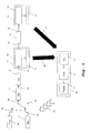
- Fig. 1 shows an embodiment of the illumination device according to the invention, the control device according to the invention and the illumination system according to the invention.
- Lighting devices 19, 23 according to the invention each include a control device 20, 24 and a luminous means 21, 25.
- the lighting devices 19, 23 are connected to a unidirectional bus system 30.
- This bus system 30 may be, for example, a DMX bus system.
- the example shown here is a serial bus system. This means that all devices connected to the bus system are connected in series.
- a controller 14 and a receiver 15 are connected to different branches of the bus system 30.
- the different branches are selected by a switch 16.
- distributors 17, 18 are connected to the bus system 30.
- a conventional illumination device 22 is furthermore connected to the bus system 30.
- the processing device 12 of the control device 10 generates a control signal, which transmits it to the transmitter 11.
- the transmitter 11 sends the control signal via a radio link 22 to the receiver 15, which is connected to the bus system 30.
- the radio connection 22 is a unidirectional connection. Instead of a radio link 22, a wired connection or an infrared connection can also be used.
- the switch 16 is switched in this embodiment so that the receiver 15 is connected to the bus system 30.
- the signal generated by the control device 10 is transmitted from the receiver 15 via the bus system 30. It is received by each device connected to the bus system 30 and sent again to the bus system 30. This is necessary because the bus system 30 is not a continuous system but consists of a series of discrete sections between the devices. In an alternative embodiment, the bus system is continuous. It is then not necessary to repeat the signal through each connected device.
- the control signal contains information indicating its destination. As soon as a device recognizes that it is the target of the control signal, the control signal is not merely repeated, but processed by the respective device.
- the illumination devices 19, 23 are the target of the transmitted control signal. The control signal is thus received and processed by the processing devices 20, 24 of the illumination devices 19, 23.
- the processing devices 20, 24 control the light sources 21, 25 connected thereto in such a way that they emit light 26, 27 modulated with a feedback signal.
- the modulated light 26, 27 is received and demodulated by the receiver 13 of the control device 10.
- the demodulated response signal is transmitted from the receiver 13 to the processing device 12.
- the bulbs can be LEDs or OLEDs or fluorescent lamps or conventional light bulbs. It is possible to use any lamps that allow modulation of the light.
- the original control signal may be a configuration signal.
- the configuration signal is received by the controllers 20, 24 of the lighting devices 19, 23.
- the lighting devices 19, 23 are configured accordingly by the control devices 20, 24.
- the control devices 20, 24 then control the respectively connected lighting means 21, 25 in such a way that they emit light 26, 27 modulated with a confirmation message.
- Another possible control signal to be sent is an operating address assignment.
- An operating address is usually much shorter than conventional device addresses assigned during production.
- the location and further information regarding the respective illumination device can be coded in the operating address.
- the address assignment is transmitted from the transmitter 11 of the control device 10 to the receiver 15 and sent by the latter via the bus system 30 to the illumination devices 19, 23.
- the controllers 20, 24 execute the address assignment. That the lighting devices 19, 23 is assigned the new operating address.
- the control devices 20, 24 then control the connected lighting means 21, 25 in such a way that they emit light 26, 27 modulated with an acknowledgment signal, which light is received again by the receiver 13 of the control device 10.
- the control device 10 may be a portable device.
- the control device 10 furthermore has a battery or a rechargeable battery.
- the receiver 13 of the control device 10 can furthermore have a directional characteristic. That is, the receiver 13 is aligned with the lighting device to be controlled and then receives only from this emitted light 26, 27. Can not be ensured that the receiver 13th only the light 26, 27 of a single illuminator 19, 23 is received, it is necessary to ensure the origin of the transmitted modulated light 26, 27.
- only one illumination device 19, 23 each may emit light 26, 27 at a time.
- the origin of the modulated light 26, 27 may be indicated in the modulation. That is to say based on the modulation of the emitted light 26, 27, the receiver 13 or the processing device 12 can determine from which illumination device 19, 23 the emitted light 26, 27 originates.
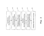
- Fig. 2 an embodiment of the control method according to the invention is shown.
- the receiver of a control device is aligned with a lighting device to be controlled. This step is only to be carried out if the receiver has sufficient directivity and only one specific lighting device is to be controlled.
- the control device sends a control signal to a bus system.
- the control signal is transmitted from the bus system to the lighting device to be controlled. A transmission to several lighting devices at the same time is possible.
- the control signal is processed by the illumination device or the illumination devices.
- modulated light is emitted by the illumination device or the illumination devices.
- the modulated light contains a feedback signal. If a plurality of lighting devices have been controlled, they either emit the modulated light in succession, or the emitted modulated light contains information about its origin.
- the modulated light is received by the control device. The controller demodulates the light and processes the feedback signal.
Abstract
Description
- Die Erfindung betrifft eine Beleuchtungseinrichtung, eine Steuerungsvorrichtung zur Steuerung von Beleuchtungseinrichtungen, ein Beleuchtungssystem und ein Verfahren zur Steuerung von Beleuchtungssystemen.
- In Beleuchtungssystemen mit einer Vielzahl von Beleuchtungseinrichtungen sind herkömmlich unidirektionale Bussysteme, wie z.B. DMX (digital multiplex) installiert. Eine Kommunikation über solche Bussysteme findet lediglich in einer Richtung statt. So Informationen lediglich von einer Steuereinrichtung an eine Beleuchtungseinrichtung übermittelt werden. Ein Rückkanal ist nicht vorgesehen. So zeigt die
DE 10 2008 056 164 A1 ein exemplarisches DMX-Beleuchtungssystem. - Nachteilhaft an solchen Beleuchtungssystemen ist, dass die angeschlossenen Beleuchtungseinrichtungen keine Rückmeldung bezüglich ihres aktuellen Status geben können.
- Zur Lösung dieses Problems wurden bidirektionale Systeme, z.B. Dali oder RDM entwickelt. Nachteilhaft hieran ist jedoch, dass eine Vielzahl von installierten unidirektionalen Systemen nicht ohne Weiteres auf bidirektionale Kommunikation umgestellt werden können. So müssten hierfür sämtliche Systemkomponenten ausgetauscht werden.
- Darüber hinaus ist ein System zur kontaktlosen optischen Datenübertragung bekannt. Dabei wird bidirektional zwischen zwei Teilnehmern moduliertes Licht ausgetauscht, welches die zu übertragenden Daten beinhaltet. So zeigt die
DE 10 2004 044 456 A1 ein solches Kommunikationssystem. - Der Erfindung liegt die Aufgabe zu Grunde, eine Beleuchtungseinrichtung, eine Vorrichtung zur Steuerung von Beleuchtungseinrichtungen, ein Beleuchtungssystem und ein Verfahren zur Steuerung von Beleuchtungssystemen zu schaffen, welche eine bidirektionale Kommunikation mit Beleuchtungseinrichtungen in einem Beleuchtungssystem ermöglichen und gleichzeitig lediglich einen geringen Aufwand ausgehend von einem bereits installierten unidirektional kommunizierenden Beleuchtungssystem erfordern.
- Die Aufgabe wird erfindungsgemäß für die Beleuchtungseinrichtung durch die Merkmale des unabhängigen Anspruchs 1, für die Steuerungsvorrichtung durch die Merkmale des unabhängigen Anspruchs 5, für das Beleuchtungssystem durch die Merkmale des unabhängigen Anspruchs 9 und für das Verfahren durch die Merkmale des unabhängigen Anspruchs 12 gelöst. Vorteilhafte Weiterbildungen sind Gegenstand der hierauf rückbezogenen Unteransprüche.
- Eine erfindungsgemäße Beleuchtungseinrichtung verfügt über ein Leuchtmittel und eine Steuerungseinrichtung. Bei dem Leuchtmittel handelt es sich z.B. um eine oder mehrere LEDs. Die Steuerungseinrichtung kann mit einem unidirektionalen Bussystem verbunden werden. Es können lediglich Informationen von dem Bussystem an die Steuerungseinrichtung übertragen werden. Die Steuerungseinrichtung ist dabei zum Empfangen und Verarbeiten von Steuersignalen über das Bussystem eingerichtet. Die Steuerungseinrichtung steuert die Abgabe von Licht durch das Leuchtmittel. So kann z.B. die Lichtstärke eingestellt werden. Die Steuerungseinrichtung steuert das Leuchtmittel derart, dass das abgegebene Licht moduliert ist. Die Steuerungseinrichtung überträgt durch die Modulation des Lichts Nachrichten. So ist eine Rückmeldung durch die Beleuchtungseinrichtung möglich, ohne das unidirektionale Bussystem modifizieren zu müssen.
- Die Nachrichten sind bevorzugt Statusnachrichten und/oder Nachrichten zur Bestätigung von empfangenen Steuersignalen und/oder Konfigurationsnachrichten. So kann eine große Vielfalt von Funktionen realisiert werden.
- Die Modulation des abgegebenen Lichts ist bevorzugt eine Amplitudenmodulation oder eine Frequenzmodulation oder eine Pulsweitenmodulation. So ist eine sichere Übertragung der Nachrichten möglich.
- Die Modulation des Lichts enthält bevorzugt Informationen, welche die Beleuchtungseinrichtungen identifizieren. So ist bei Einsatz mehrerer Beleuchtungseinrichtungen stets klar, von welcher Beleuchtungseinrichtung die Nachrichten ausgehen.
- Eine erfindungsgemäße Steuerungsvorrichtung zur Steuerung von Beleuchtungseinrichtungen beinhaltet einen Empfänger, eine Verarbeitungseinrichtung und einen Sender. Der Empfänger empfängt moduliertes Licht von einer Beleuchtungseinrichtung. Dieses Licht ist moduliert. Die Verarbeitungseinrichtung verarbeitet in der Modulation enthaltene Nachrichten. Die Verarbeitungseinrichtung erzeugt Steuersignale, welche der Sender zumindest mittelbar an die Beleuchtungseinrichtung sendet. So ist eine bidirektionale Kommunikation zu der Beleuchtungseinrichtung gewährleistet.
- Die von der Verarbeitungseinrichtung erzeugten Steuersignale sind bevorzugt Statusanfragen oder Konfigurationssignale. So ist eine Vielzahl von Funktionen realisierbar.
- Der Empfänger weist vorteilhafterweise eine Richtcharakteristik auf. Der Empfänger empfängt, wenn er auf eine Beleuchtungseinrichtung ausgerichtet ist, bevorzugt weitgehend lediglich von dieser Beleuchtungseinrichtung abgegebenes Licht. So ist sichergestellt, dass gleichzeitig mit genau einer Beleuchtungseinrichtung kommuniziert wird.
- Ein erfindungsgemäßes Beleuchtungssystem beinhaltet eine erfindungsgemäße Beleuchtungseinrichtung, eine erfindungsgemäße Steuerungsvorrichtung und ein ausschließlich unidirektionales Bussystem. Die Steuerungsvorrichtung empfängt Licht von der Beleuchtungseinrichtung und sendet Steuersignale zumindest mittelbar über das Bussystem an die Beleuchtungseinrichtung. So ist eine bidirektionale Kommunikation zwischen der Beleuchtungseinrichtung und der Steuerungsvorrichtung ohne Modifikation des Bussystems möglich.
- Der Sender der Steuerungsvorrichtung ist vorteilhafterweise über eine Kabelverbindung oder über eine Funkverbindung oder über eine Infrarotverbindung mit dem Bussystem verbunden. So ist ein sicherer und flexibler Anschluss möglich.
- Das Beleuchtungssystem weist dabei bevorzugt mehrere Beleuchtungseinrichtungen auf. Die Modulation des Lichts beinhaltet vorteilhafterweise Informationen, welche anzeigen, welche Beleuchtungseinrichtung das Licht abgegeben hat. So können in Räumen mit mehreren Beleuchtungseinrichtungen diese gleichzeitig gesteuert werden.
- Bei einem erfindungsgemäßen Verfahren zur Steuerung von Beleuchtungssystemen beinhaltet das Beleuchtungssystem zumindest eine Beleuchtungseinrichtung, eine Steuerungseinrichtung und ein ausschließlich unidirektionales Bussystem. Von der Steuerungseinrichtung werden Steuersignale über das Bussystem an die Beleuchtungseinrichtung übertragen. Die Steuersignale werden von der Beleuchtungseinrichtung empfangen und verarbeitet. Moduliertes Licht wird von der Beleuchtungseinrichtung abgegeben. Die Modulation des Lichts beinhaltet dabei Nachrichten. Das modulierte Licht wird von der Steuerungseinrichtung empfangen. Die Nachrichten werden von der Steuerungseinrichtung verarbeitet. Eine bidirektionale Kommunikation ist so möglich, ohne das unidirektionale Bussystem zu modifizieren.
- Nachfolgend wird die Erfindung anhand der Zeichnung, in der ein vorteilhaftes Ausführungsbeispiel der Erfindung dargestellt ist, beispielhaft beschrieben. In der Zeichnung zeigen:
- Fig. 1
- ein Ausführungsbeispiel des erfindungsgemäßen Beleuchtungssystems, und
- Fig. 2
- ein Ausführungsbeispiel des erfindungsgemäßen Verfahrens.
- Zunächst werden anhand der
Fig. 1 der Aufbau und die Funktionsweise der Beleuchtungseinrichtung, der Steuerungsvorrichtung und des Beleuchtungssystems erläutert. MittelsFig. 2 wird anschließend die Funktionsweise des Steuerverfahrens gezeigt. -
Fig. 1 zeigt ein Ausführungsbeispiel der erfindungsgemäßen Beleuchtungseinrichtung, der erfindungsgemäßen Steuerungsvorrichtung und des erfindungsgemäßen Beleuchtungssystems. Erfindungsgemäße Beleuchtungseinrichtungen 19, 23 beinhalten jeweils eine Steuerungseinrichtung 20, 24 und ein Leuchtmittel 21, 25. Die Beleuchtungseinrichtungen 19, 23 sind dabei mit einem unidirektionalen Bussystem 30 verbunden. Bei diesem Bussystem 30 kann es sich z.B. um ein DMX-Bussystem handeln. In dem hier dargestellten Beispiel handelt es sich um ein serielles Bussystem. D.h. sämtliche an das Bussystem angeschlossene Geräte sind in Serie geschaltet. - An das Bussystem 30 ist eine Vielzahl weiterer Geräte angeschlossen. Eine Steuerungseinrichtung 14 und ein Empfänger 15 sind mit unterschiedlichen Zweigen des Bussystems 30 verbunden. Die unterschiedlichen Zweige werden von einem Schalter 16 selektiert. Darüber hinaus sind Verteiler 17, 18 (splitter) mit dem Bussystem 30 verbunden. Neben den erfindungsgemäßen Beleuchtungseinrichtungen 19, 23 ist weiterhin eine herkömmliche Beleuchtungseinrichtung 22 mit dem Bussystem 30 verbunden.
- Die erfindungsgemäße Steuerungsvorrichtung 10 beinhaltet eine Verarbeitungseinrichtung 12, einen Sender 11 und einen Empfänger 13. Der Sender 11 und der Empfänger 13 sind dabei jeweils mit der Verarbeitungseinrichtung 12 verbunden.
- Die Verarbeitungseinrichtung 12 der Steuerungsvorrichtung 10 erzeugt ein Steuersignal, welches sie an den Sender 11 überträgt. Der Sender 11 sendet das Steuersignal über eine Funkverbindung 22 an den Empfänger 15, welcher mit dem Bussystem 30 verbunden ist. Es handelt sich bei der Funkverbindung 22 um eine unidirektionale Verbindung. Anstatt einer Funkverbindung 22 kann auch eine drahtgebundene Verbindung oder eine Infrarotverbindung eingesetzt werden. Der Schalter 16 ist in diesem Ausführungsbeispiel so geschaltet, dass der Empfänger 15 mit dem Bussystem 30 verbunden ist.
- Das von der Steuerungsvorrichtung 10 erzeugte Signal wird von dem Empfänger 15 über das Bussystem 30 übertragen. Es wird dabei von jedem an das Bussystem 30 angeschlossenen Gerät empfangen und erneut an das Bussystem 30 gesendet. Dies ist notwendig, da das Bussystem 30 kein durchgängiges System ist, sondern aus einer Reihe von einzelnen Abschnitten zwischen den Geräten besteht. In einem alternativen Ausführungsbeispiel ist das Bussystem durchgängig. Es ist dann nicht notwendig, das Signal durch jedes angeschlossene Gerät zu wiederholen. Das Steuersignal enthält dabei Informationen, welche sein Ziel angeben. Sobald ein Gerät erkennt, dass es das Ziel des Steuersignals ist, wird das Steuersignal nicht lediglich wiederholt, sondern durch das jeweilige Gerät verarbeitet. In diesem Ausführungsbeispiel sind die Beleuchtungseinrichtungen 19, 23 Ziel des ausgesendeten Steuersignals. Das Steuersignal wird somit von den Verarbeitungseinrichtungen 20, 24 der Beleuchtungseinrichtungen 19, 23 empfangen und verarbeitet.
- Sofern das Steuersignal, wie in diesem Beispiel, eine Rückmeldung erfordert, steuern die Verarbeitungseinrichtungen 20, 24, die daran angeschlossenen Leuchtmittel 21, 25 derart an, dass diese mit einem Rückmeldesignal moduliertes Licht 26, 27 aussenden. Das modulierte Licht 26, 27 wird von dem Empfänger 13 der Steuerungsvorrichtung 10 empfangen und demoduliert. Das demodulierte Rückmeldungssignal wird von dem Empfänger 13 an die Verarbeitungseinrichtung 12 übertragen. Bei den Leuchtmitteln kann es sich um LEDs oder OLEDs oder Leuchtstofflampen oder herkömmliche Glühlampen handeln. Ein Einsatz jeglicher Leuchtmittel, welche eine Modulation des Lichts zulassen, ist möglich.
- Bei dem ursprünglichen Steuersignal kann es sich z.B. um eine Statusanfrage handeln. Die Steuerungseinrichtungen 20, 24 ermitteln nach Erhalt dieses Steuersignals den Status ihrer jeweiligen Beleuchtungseinrichtung 19, 23 und steuern das jeweilige angeschlossene Leuchtmittel 21, 25 derart, dass diese Licht aussenden, welches mit einer entsprechenden Statusmeldung moduliert ist.
- Alternativ kann es sich bei dem ursprünglichen Steuersignal um ein Konfigurationssignal handeln. Das Konfigurationssignal wird von den Steuerungseinrichtungen 20, 24 der Beleuchtungseinrichtungen 19, 23 empfangen. Die Beleuchtungseinrichtungen 19, 23 werden durch die Steuerungseinrichtungen 20, 24 entsprechend konfiguriert. Anschließend steuern die Steuereinrichtungen 20, 24 die jeweils angeschlossenen Leuchtmittel 21, 25 derart an, dass diese mit einer Bestätigungsmeldung moduliertes Licht 26, 27 aussenden.
- Ein weiteres mögliches auszusendendes Steuersignal ist eine Betriebsadress-Zuweisung. Dabei weist die Verarbeitungseinrichtung 12 der Steuerungsvorrichtung 10 einer bestimmten Beleuchtungseinrichtung 19, 23 eine Betriebsadresse zu. Eine Betriebsadresse ist üblicherweise deutlich kürzer als herkömmlich bei der Herstellung vergebene Geräteadressen. Darüber hinaus können in der Betriebsadresse der Standort und weitere Informationen bezüglich der jeweiligen Beleuchtungseinrichtung codiert sein. Die Adresszuweisung wird von dem Sender 11 der Steuerungsvorrichtung 10 an den Empfänger 15 übertragen und von diesem über das Bussystem 30 an die Beleuchtungseinrichtungen 19, 23 gesendet. Die Steuerungseinrichtungen 20, 24 führen die Adresszuweisung aus. D.h. den Beleuchtungseinrichtungen 19, 23 wird die neue Betriebsadresse zugewiesen. Die Steuerungseinrichtungen 20, 24 steuern anschließend die angeschlossenen Leuchtmittel 21, 25 derart an, dass diese mit einem Bestätigungssignal moduliertes Licht 26, 27 aussenden, welches erneut von dem Empfänger 13 der Steuerungsvorrichtung 10 empfangen wird.
- Es so möglich, in bestehenden Beleuchtungssystemen lediglich die Beleuchtungseinrichtungen auszutauschen, um eine bidirektionale Kommunikation zu ermöglichen. Das Bussystem und die weiteren angeschlossenen Geräte können unverändert bleiben, da der Rückkanal der bidirektionalen Kommunikation nicht über sie läuft.
- Bei der Steuerungsvorrichtung 10 kann es sich um ein tragbares Gerät handeln. In diesem Fall verfügt die Steuerungseinrichtung 10 weiterhin über eine Batterie oder einen Akku. Zur gezielten Auswahl einzelner zu steuernder Beleuchtungseinrichtungen kann der Empfänger 13 der Steuerungsvorrichtung 10 darüber hinaus über eine Richtcharakteristik verfügen. D.h. der Empfänger 13 wird auf die zu steuernde Beleuchtungseinrichtung ausgerichtet und empfängt dann lediglich von dieser ausgesendetes Licht 26, 27. Kann nicht sichergestellt werden, dass der Empfänger 13 lediglich das Licht 26, 27 einer einzelnen Beleuchtungseinrichtung 19,23 empfängt, ist es notwendig, den Ursprung des ausgesendeten modulierten Lichts 26, 27 sicherzustellen. Hierzu kann beispielsweise zu einem Zeitpunkt lediglich jeweils eine Beleuchtungseinrichtung 19, 23 Licht 26, 27 emittieren. Alternativ kann der Ursprung des modulierten Lichts 26, 27 in der Modulation angegeben sein. D.h. anhand der Modulation des ausgesendeten Lichts 26, 27 kann der Empfänger 13 bzw. die Verarbeitungseinrichtung 12 bestimmen, von welcher Beleuchtungseinrichtung 19, 23 das ausgesendete Licht 26, 27 stammt.
- In
Fig. 2 wird ein Ausführungsbeispiel des erfindungsgemäßen Steuerverfahrens gezeigt. In einem optionalen ersten Schritt wird der Empfänger einer Steuerungsvorrichtung auf eine zu steuernde Beleuchtungseinrichtung ausgerichtet. Dieser Schritt ist nur durchzuführen, wenn der Empfänger über eine ausreichende Richtcharakteristik verfügt und nur eine bestimmte Beleuchtungseinrichtung gesteuert werden soll. In einem zweiten Schritt sendet die Steuerungsvorrichtung ein Steuersignal an ein Bussystem. In einem anschließenden dritten Schritt 41 wird das Steuersignal von dem Bussystem an die zu steuernde Beleuchtungseinrichtung übertragen. Auch eine Übertragung an mehrere Beleuchtungseinrichtungen gleichzeitig ist möglich. - In einem folgenden vierten Schritt 42 wird das Steuersignal durch die Beleuchtungseinrichtung bzw. die Beleuchtungseinrichtungen verarbeitet. In einem fünften Schritt 43 wird moduliertes Licht durch die Beleuchtungseinrichtung bzw. die Beleuchtungseinrichtungen ausgesendet. Das modulierte Licht beinhaltet dabei ein Rückmeldungssignal. Wurden mehrere Beleuchtungseinrichtungen gesteuert, so senden diese entweder nacheinander das modulierte Licht aus, oder das ausgesendete modulierte Licht beinhaltet Informationen über seinen Ursprung. In einem abschließenden sechsten Schritt 44 wird das modulierte Licht durch die Steuerungsvorrichtung empfangen. Die Steuerungsvorrichtung demoduliert das Licht und verarbeitet das Rückmeldungssignal.
- Die Erfindung ist nicht auf das dargestellte Ausführungsbeispiel beschränkt. Neben dem erwähnten DMX-Verfahren können auch andere Übertragungsverfahren in unidirektionalen Bussystemen eingesetzt werden. Alle vorstehend beschriebenen Merkmale oder in den Figuren gezeigten Merkmale sind im Rahmen der Erfindung beliebig vorteilhaft miteinander kombinierbar.
Claims (15)
- Beleuchtungseinrichtung (19,23) mit einem Leuchtmittel (21, 25) und einer Steuerungseinrichtung (20, 24),
wobei die Steuerungseinrichtung (20, 24) mit einem unidirektionalen Bussystem (30) verbindbar ist,
wobei die Steuerungseinrichtung (20, 24) zum Empfangen und Verarbeiten von Steuersignalen über das Bussystem (30) eingerichtet ist, und
wobei die Steuerungseinrichtung (20, 24) eine Abgabe von Licht (26, 27) durch das Leuchtmittel (21, 25) steuert,
dadurch gekennzeichnet,
dass die Steuerungseinrichtung (20, 24) das Leuchtmittel (21, 25) derart steuert, dass das abgegebene Licht (26, 27) moduliert ist, und
dass die Steuerungseinrichtung (20, 24) durch die Modulation des Lichts (26, 27) Nachrichten überträgt. - Beleuchtungseinrichtung (19, 23) nach Anspruch 1,
dadurch gekennzeichnet,
dass die Nachrichten Statusnachrichten und/oder Nachrichten zur Bestätigung von empfangenen Steuersignalen und/oder Konfigurationsnachrichten sind. - Beleuchtungseinrichtung (19, 23) nach Anspruch 1 oder 2,
dadurch gekennzeichnet,
dass die Modulation des abgegebenen Lichts (26, 27) eine Amplitudenmodulation oder eine Frequenzmodulation oder eine Pulsweitenmodulation ist. - Beleuchtungseinrichtung (19, 23) nach einem der Ansprüche 1 bis 3,
dadurch gekennzeichnet,
dass die Modulation des Lichts (26, 27) Informationen enthält, welche die Beleuchtungseinrichtung (19, 23) identifizieren. - Steuerungsvorrichtung (10) zur Steuerung von Beleuchtungseinrichtungen (19, 23), wobei die Steuerungsvorrichtung (10) über einen Empfänger (13), eine Verarbeitungseinrichtung (12) und einen Sender (11) verfügt,
wobei der Empfänger (13) moduliertes Licht (26, 27) von einer Beleuchtungseinrichtung (19, 23) empfängt,
wobei die Verarbeitungseinrichtung (12) in der Modulation des Lichts (26, 27) enthaltene Nachrichten verarbeitet, und
wobei die Verarbeitungseinrichtung (12) Steuersignale erzeugt und der Sender (11) diese zumindest mittelbar an die Beleuchtungseinrichtung (19, 23) sendet. - Steuerungsvorrichtung (10) nach Anspruch 5,
dadurch gekennzeichnet,
dass die von der Verarbeitungseinrichtung (12) erzeugten Steuersignale Statusanfragen oder Konfigurationssignale sind. - Steuerungsvorrichtung (10) nach Anspruch 5 oder 6,
dadurch gekennzeichnet,
dass die Modulation des empfangenen Lichts (26, 27) eine Amplitudenmodulation oder eine Frequenzmodulation oder eine Pulsweitenmodulation ist. - Steuerungsvorrichtung (10) nach einem der Anspruch 5 bis 7,
dadurch gekennzeichnet,
dass der Empfänger (13) eine Richtcharakteristik aufweist, und
dass der Empfänger (13), wenn er auf eine Beleuchtungseinrichtung (19, 23) ausgerichtet ist, weitgehend lediglich von dieser Beleuchtungseinrichtung (19, 23) abgegebenes Licht (26, 27) empfängt. - Beleuchtungssystem mit zumindest einer Beleuchtungseinrichtung (19, 23) nach Anspruch 1, einer Steuerungsvorrichtung (10) nach Anspruch 5 und einem unidirektionalen Bussystem (30),
wobei die Steuerungsvorrichtung (10) Licht (26, 27) von der Beleuchtungseinrichtung (19, 23) empfängt und Steuersignale zumindest mittelbar über das Bussystem (30) an die Beleuchtungseinrichtung (19,23) sendet. - Beleuchtungssystem nach Anspruch 9,
dadurch gekennzeichnet,
dass der Sender (11) der Steuerungsvorrichtung (10) über eine Kabelverbindung oder über eine Funkverbindung (22) oder über eine Infrarotverbindung mit dem Bussystem (30) verbunden ist. - Beleuchtungssystem nach Anspruch 9 oder 10,
dadurch gekennzeichnet,
dass das Beleuchtungssystem mehrere Beleuchtungseinrichtungen (19, 23) aufweist, und
dass die Modulation des Lichts (26, 27) Informationen enthält, welche anzeigen, welche Beleuchtungseinrichtung (19, 23) das Licht abgegeben hat. - Verfahren zur Steuerung von Beleuchtungssystemen,
wobei das Beleuchtungssystem über zumindest eine Beleuchtungseinrichtung (19, 23), eine Steuerungseinrichtung (10) und ein unidirektionales Bussystem (30) verfügt, wobei von der Steuerungseinrichtung (10) Steuersignale über das Bussystem (30) an die Beleuchtungseinrichtung (19, 23) übertragen werden,
wobei die Steuersignale von der Beleuchtungseinrichtung (19, 23) empfangen und verarbeitet werden,
wobei moduliertes Licht (26, 27) von der Beleuchtungseinrichtung (19, 23) abgegeben wird, und
wobei die Modulation des Lichts (26, 27) Nachrichten beinhaltet,
wobei das modulierte Licht (26, 27) von der Steuerungseinrichtung (10) empfangen wird und die Nachrichten von der Steuerungseinrichtung (10) verarbeitet werden. - Verfahren nach Anspruch 12,
dadurch gekennzeichnet,
dass die Nachrichten Statusnachrichten und/oder Nachrichten zur Bestätigung von empfangenen Steuersignalen und/oder Konfigurationsnachrichten sind, und
dass die erzeugten Steuersignale Statusanfragen oder Konfigurationssignale sind. - Verfahren nach Anspruch 12 oder 13,
dadurch gekennzeichnet,
dass das Beleuchtungssystem mehrere Beleuchtungseinrichtungen (19, 23) aufweist, dass die Steuerungseinrichtung (10) auf eine zu steuernde Beleuchtungseinrichtung (19, 23) ausgerichtet wird,
dass die Steuerungseinrichtung (10) weitgehend lediglich von dieser Beleuchtungseinrichtung (19, 23) abgegebenes Licht (26, 27) empfängt, und
dass die Steuerungseinrichtung (10) ausschließlich die Beleuchtungseinrichtung (19, 23) steuert, auf welche sie ausgerichtet ist. - Verfahren nach einem der Ansprüche 12 bis 14,
dadurch gekennzeichnet,
dass das Beleuchtungssystem mehrere Beleuchtungseinrichtungen (19, 23) aufweist, und
dass die Modulation des Lichts (26, 27) Informationen enthält, welche anzeigen, welche Beleuchtungseinrichtung (19, 23) das Licht abgegeben hat.
Applications Claiming Priority (1)
| Application Number | Priority Date | Filing Date | Title |
|---|---|---|---|
| DE102010028249A DE102010028249A1 (de) | 2010-04-27 | 2010-04-27 | System und Verfahren zur bidirektionalen Kommunikation mit LED-Leuchten |
Publications (2)
| Publication Number | Publication Date |
|---|---|
| EP2383909A1 true EP2383909A1 (de) | 2011-11-02 |
| EP2383909B1 EP2383909B1 (de) | 2014-08-27 |
Family
ID=44351777
Family Applications (1)
| Application Number | Title | Priority Date | Filing Date |
|---|---|---|---|
| EP11163879.7A Active EP2383909B1 (de) | 2010-04-27 | 2011-04-27 | System und Verfahren zur bidirektionalen Kommunikation mit LED-Leuchten |
Country Status (2)
| Country | Link |
|---|---|
| EP (1) | EP2383909B1 (de) |
| DE (1) | DE102010028249A1 (de) |
Cited By (2)
| Publication number | Priority date | Publication date | Assignee | Title |
|---|---|---|---|---|
| WO2017050706A1 (de) * | 2015-09-23 | 2017-03-30 | Tridonic Gmbh & Co Kg | Mobilgerät und verfahren zum konfigurieren und/oder kommissionieren eines beleuchtungssystems und beleuchtungssystemeinrichtung |
| EP3434071B1 (de) | 2016-03-21 | 2021-03-03 | INOVA Semiconductors GmbH | Verfahren und vorrichtung zur bidirektionalen kommunikation |
Families Citing this family (2)
| Publication number | Priority date | Publication date | Assignee | Title |
|---|---|---|---|---|
| DE102012204686B3 (de) * | 2012-03-23 | 2013-05-23 | Siemens Aktiengesellschaft | Verfahren zur Konfiguration einer Beleuchtungsanlage |
| DE102014209131A1 (de) * | 2014-05-14 | 2015-11-19 | Robert Bosch Gmbh | Verfahren und System zur Steuerung einer Beleuchtungsanlage mit einem mobilen Mittel |
Citations (5)
| Publication number | Priority date | Publication date | Assignee | Title |
|---|---|---|---|---|
| US4856090A (en) * | 1984-05-22 | 1989-08-08 | Canon Kabushiki Kaisha | Light communication equipment |
| WO1999049446A1 (en) * | 1998-03-20 | 1999-09-30 | Versitech Ltd. | Tricolor led display system having audio output |
| WO2002025842A2 (en) * | 2000-09-19 | 2002-03-28 | Color Kinetics Incorporated | Universal lighting network method and system |
| DE102004044456A1 (de) | 2004-09-14 | 2006-03-30 | Siemens Ag | System zur optischen Datenübertragung |
| DE102008056164A1 (de) | 2008-07-29 | 2010-02-04 | Tridonicatco Gmbh & Co. Kg | Zuweisung einer Betriebsadresse an ein busfähiges Betriebsgerät für Leuchtmittel |
Family Cites Families (4)
| Publication number | Priority date | Publication date | Assignee | Title |
|---|---|---|---|---|
| WO2002013490A2 (en) * | 2000-08-07 | 2002-02-14 | Color Kinetics Incorporated | Automatic configuration systems and methods for lighting and other applications |
| CN101164381B (zh) * | 2005-04-22 | 2011-07-06 | 皇家飞利浦电子股份有限公司 | 用于照明控制的方法及系统 |
| PL1927272T5 (pl) * | 2005-09-07 | 2022-06-27 | Signify Holding B.V. | Urządzenie uruchamiające oświetlenie oraz sposób |
| ES2357086T3 (es) * | 2007-07-18 | 2011-04-18 | Koninklijke Philips Electronics N.V. | Procedimiento para procesar luz en una estructura y sistema de iluminación. |
-
2010
- 2010-04-27 DE DE102010028249A patent/DE102010028249A1/de not_active Withdrawn
-
2011
- 2011-04-27 EP EP11163879.7A patent/EP2383909B1/de active Active
Patent Citations (5)
| Publication number | Priority date | Publication date | Assignee | Title |
|---|---|---|---|---|
| US4856090A (en) * | 1984-05-22 | 1989-08-08 | Canon Kabushiki Kaisha | Light communication equipment |
| WO1999049446A1 (en) * | 1998-03-20 | 1999-09-30 | Versitech Ltd. | Tricolor led display system having audio output |
| WO2002025842A2 (en) * | 2000-09-19 | 2002-03-28 | Color Kinetics Incorporated | Universal lighting network method and system |
| DE102004044456A1 (de) | 2004-09-14 | 2006-03-30 | Siemens Ag | System zur optischen Datenübertragung |
| DE102008056164A1 (de) | 2008-07-29 | 2010-02-04 | Tridonicatco Gmbh & Co. Kg | Zuweisung einer Betriebsadresse an ein busfähiges Betriebsgerät für Leuchtmittel |
Cited By (2)
| Publication number | Priority date | Publication date | Assignee | Title |
|---|---|---|---|---|
| WO2017050706A1 (de) * | 2015-09-23 | 2017-03-30 | Tridonic Gmbh & Co Kg | Mobilgerät und verfahren zum konfigurieren und/oder kommissionieren eines beleuchtungssystems und beleuchtungssystemeinrichtung |
| EP3434071B1 (de) | 2016-03-21 | 2021-03-03 | INOVA Semiconductors GmbH | Verfahren und vorrichtung zur bidirektionalen kommunikation |
Also Published As
| Publication number | Publication date |
|---|---|
| DE102010028249A1 (de) | 2011-10-27 |
| EP2383909B1 (de) | 2014-08-27 |
Similar Documents
| Publication | Publication Date | Title |
|---|---|---|
| EP1659832B1 (de) | Verfahren zur Vergabe von Kurzadressen in Beleuchtungsanlagen | |
| DE4422215A1 (de) | Steuersystem für mehrere verteilt anzuordnende Verbraucher, sowie Verfahren zum In-Betrieb-Setzen eines solchen Steuersystems | |
| DE102006019144A1 (de) | Leuchte | |
| DE102008055798A1 (de) | Warnleuchte mit einer Sockeleinheit und wenigstens einer Leuchteinheit | |
| EP1555859A1 (de) | Ansteuerung von Leuchtmittel-Betriebsgeräten über einen modulierten DC-Bus | |
| EP1891838A1 (de) | Ermittlung der busadresse eines teilnehmers in einem beleuchtungs-bussystem | |
| DE102012205964B4 (de) | Beleuchtungssystem sowie Steuereinheit und Verfahren hierfür | |
| DE102008061089A1 (de) | Adressvergabe für busfähige Leuchtmittel-Betriebsgeräte, insbesondere für LEDs | |
| EP2383909B1 (de) | System und Verfahren zur bidirektionalen Kommunikation mit LED-Leuchten | |
| DE102017104946A1 (de) | Beleuchtungssystem, beleuchtungsvorrichtungen, und endgerät | |
| WO2011110663A1 (de) | Bus -gebäudetechniksystem mit daisy-chain topologie | |
| DE102008056164A1 (de) | Zuweisung einer Betriebsadresse an ein busfähiges Betriebsgerät für Leuchtmittel | |
| EP1727398A2 (de) | Leuchte mit Speicherelement | |
| DE102010020960A1 (de) | Leuchte und Leuchtensteuerungssystem | |
| DE102018116970A1 (de) | Einstellvorrichtung und pairing-verfahren für eine beleuchtungsanlage | |
| DE102016109667A1 (de) | Modulationseinrichtung und Beleuchtungseinrichtung | |
| EP3741192B1 (de) | Installation und konfiguration von dali-betriebsgeräten für leuchtmittel | |
| DE102017111247A1 (de) | Drahtlose Kommunikationsvorrichtung und Beleuchtungssystem | |
| EP1871145A1 (de) | Leuchtensystem | |
| EP3251469A1 (de) | Verfahren zum betreiben von geräten in einem beleuchtungssystem | |
| DE102010000902A1 (de) | Optische Signalausgabe von Betriebsparametern bei einer LED-Beleuchtung | |
| DE102014202720A1 (de) | Beleuchtungssystem | |
| DE102012210959A1 (de) | Steuerungssystem für verteilt angeordnete Verbraucher und Verfahren zur Inbetriebnahme des Systems | |
| DE202006006636U1 (de) | Leuchte | |
| EP2779801A2 (de) | Beleuchtungssystem und Verfahren zum Steuern eines Beleuchtungssystems |
Legal Events
| Date | Code | Title | Description |
|---|---|---|---|
| AK | Designated contracting states |
Kind code of ref document: A1 Designated state(s): AL AT BE BG CH CY CZ DE DK EE ES FI FR GB GR HR HU IE IS IT LI LT LU LV MC MK MT NL NO PL PT RO RS SE SI SK SM TR |
|
| AX | Request for extension of the european patent |
Extension state: BA ME |
|
| PUAI | Public reference made under article 153(3) epc to a published international application that has entered the european phase |
Free format text: ORIGINAL CODE: 0009012 |
|
| 17P | Request for examination filed |
Effective date: 20120502 |
|
| 17Q | First examination report despatched |
Effective date: 20130729 |
|
| REG | Reference to a national code |
Ref country code: DE Ref legal event code: R079 Ref document number: 502011004169 Country of ref document: DE Free format text: PREVIOUS MAIN CLASS: H04B0010100000 Ipc: H04B0010116000 |
|
| RIC1 | Information provided on ipc code assigned before grant |
Ipc: H04B 10/116 20130101AFI20140221BHEP |
|
| GRAP | Despatch of communication of intention to grant a patent |
Free format text: ORIGINAL CODE: EPIDOSNIGR1 |
|
| INTG | Intention to grant announced |
Effective date: 20140410 |
|
| GRAS | Grant fee paid |
Free format text: ORIGINAL CODE: EPIDOSNIGR3 |
|
| GRAA | (expected) grant |
Free format text: ORIGINAL CODE: 0009210 |
|
| AK | Designated contracting states |
Kind code of ref document: B1 Designated state(s): AL AT BE BG CH CY CZ DE DK EE ES FI FR GB GR HR HU IE IS IT LI LT LU LV MC MK MT NL NO PL PT RO RS SE SI SK SM TR |
|
| REG | Reference to a national code |
Ref country code: GB Ref legal event code: FG4D Free format text: NOT ENGLISH |
|
| REG | Reference to a national code |
Ref country code: CH Ref legal event code: NV Representative=s name: FIAMMENGHI-FIAMMENGHI, CH Ref country code: CH Ref legal event code: EP |
|
| REG | Reference to a national code |
Ref country code: AT Ref legal event code: REF Ref document number: 684943 Country of ref document: AT Kind code of ref document: T Effective date: 20140915 |
|
| REG | Reference to a national code |
Ref country code: IE Ref legal event code: FG4D Free format text: LANGUAGE OF EP DOCUMENT: GERMAN |
|
| REG | Reference to a national code |
Ref country code: DE Ref legal event code: R096 Ref document number: 502011004169 Country of ref document: DE Effective date: 20141009 |
|
| REG | Reference to a national code |
Ref country code: LT Ref legal event code: MG4D |
|
| REG | Reference to a national code |
Ref country code: NL Ref legal event code: VDEP Effective date: 20140827 |
|
| PG25 | Lapsed in a contracting state [announced via postgrant information from national office to epo] |
Ref country code: FI Free format text: LAPSE BECAUSE OF FAILURE TO SUBMIT A TRANSLATION OF THE DESCRIPTION OR TO PAY THE FEE WITHIN THE PRESCRIBED TIME-LIMIT Effective date: 20140827 Ref country code: SE Free format text: LAPSE BECAUSE OF FAILURE TO SUBMIT A TRANSLATION OF THE DESCRIPTION OR TO PAY THE FEE WITHIN THE PRESCRIBED TIME-LIMIT Effective date: 20140827 Ref country code: NO Free format text: LAPSE BECAUSE OF FAILURE TO SUBMIT A TRANSLATION OF THE DESCRIPTION OR TO PAY THE FEE WITHIN THE PRESCRIBED TIME-LIMIT Effective date: 20141127 Ref country code: BG Free format text: LAPSE BECAUSE OF FAILURE TO SUBMIT A TRANSLATION OF THE DESCRIPTION OR TO PAY THE FEE WITHIN THE PRESCRIBED TIME-LIMIT Effective date: 20141127 Ref country code: LT Free format text: LAPSE BECAUSE OF FAILURE TO SUBMIT A TRANSLATION OF THE DESCRIPTION OR TO PAY THE FEE WITHIN THE PRESCRIBED TIME-LIMIT Effective date: 20140827 Ref country code: GR Free format text: LAPSE BECAUSE OF FAILURE TO SUBMIT A TRANSLATION OF THE DESCRIPTION OR TO PAY THE FEE WITHIN THE PRESCRIBED TIME-LIMIT Effective date: 20141128 Ref country code: ES Free format text: LAPSE BECAUSE OF FAILURE TO SUBMIT A TRANSLATION OF THE DESCRIPTION OR TO PAY THE FEE WITHIN THE PRESCRIBED TIME-LIMIT Effective date: 20140827 Ref country code: PT Free format text: LAPSE BECAUSE OF FAILURE TO SUBMIT A TRANSLATION OF THE DESCRIPTION OR TO PAY THE FEE WITHIN THE PRESCRIBED TIME-LIMIT Effective date: 20141229 |
|
| PG25 | Lapsed in a contracting state [announced via postgrant information from national office to epo] |
Ref country code: LV Free format text: LAPSE BECAUSE OF FAILURE TO SUBMIT A TRANSLATION OF THE DESCRIPTION OR TO PAY THE FEE WITHIN THE PRESCRIBED TIME-LIMIT Effective date: 20140827 Ref country code: HR Free format text: LAPSE BECAUSE OF FAILURE TO SUBMIT A TRANSLATION OF THE DESCRIPTION OR TO PAY THE FEE WITHIN THE PRESCRIBED TIME-LIMIT Effective date: 20140827 Ref country code: RS Free format text: LAPSE BECAUSE OF FAILURE TO SUBMIT A TRANSLATION OF THE DESCRIPTION OR TO PAY THE FEE WITHIN THE PRESCRIBED TIME-LIMIT Effective date: 20140827 Ref country code: CY Free format text: LAPSE BECAUSE OF FAILURE TO SUBMIT A TRANSLATION OF THE DESCRIPTION OR TO PAY THE FEE WITHIN THE PRESCRIBED TIME-LIMIT Effective date: 20140827 Ref country code: IS Free format text: LAPSE BECAUSE OF FAILURE TO SUBMIT A TRANSLATION OF THE DESCRIPTION OR TO PAY THE FEE WITHIN THE PRESCRIBED TIME-LIMIT Effective date: 20141227 |
|
| PG25 | Lapsed in a contracting state [announced via postgrant information from national office to epo] |
Ref country code: NL Free format text: LAPSE BECAUSE OF FAILURE TO SUBMIT A TRANSLATION OF THE DESCRIPTION OR TO PAY THE FEE WITHIN THE PRESCRIBED TIME-LIMIT Effective date: 20140827 |
|
| PG25 | Lapsed in a contracting state [announced via postgrant information from national office to epo] |
Ref country code: IT Free format text: LAPSE BECAUSE OF FAILURE TO SUBMIT A TRANSLATION OF THE DESCRIPTION OR TO PAY THE FEE WITHIN THE PRESCRIBED TIME-LIMIT Effective date: 20140827 Ref country code: DK Free format text: LAPSE BECAUSE OF FAILURE TO SUBMIT A TRANSLATION OF THE DESCRIPTION OR TO PAY THE FEE WITHIN THE PRESCRIBED TIME-LIMIT Effective date: 20140827 Ref country code: EE Free format text: LAPSE BECAUSE OF FAILURE TO SUBMIT A TRANSLATION OF THE DESCRIPTION OR TO PAY THE FEE WITHIN THE PRESCRIBED TIME-LIMIT Effective date: 20140827 Ref country code: SK Free format text: LAPSE BECAUSE OF FAILURE TO SUBMIT A TRANSLATION OF THE DESCRIPTION OR TO PAY THE FEE WITHIN THE PRESCRIBED TIME-LIMIT Effective date: 20140827 Ref country code: CZ Free format text: LAPSE BECAUSE OF FAILURE TO SUBMIT A TRANSLATION OF THE DESCRIPTION OR TO PAY THE FEE WITHIN THE PRESCRIBED TIME-LIMIT Effective date: 20140827 Ref country code: RO Free format text: LAPSE BECAUSE OF FAILURE TO SUBMIT A TRANSLATION OF THE DESCRIPTION OR TO PAY THE FEE WITHIN THE PRESCRIBED TIME-LIMIT Effective date: 20140827 |
|
| REG | Reference to a national code |
Ref country code: DE Ref legal event code: R097 Ref document number: 502011004169 Country of ref document: DE |
|
| PG25 | Lapsed in a contracting state [announced via postgrant information from national office to epo] |
Ref country code: PL Free format text: LAPSE BECAUSE OF FAILURE TO SUBMIT A TRANSLATION OF THE DESCRIPTION OR TO PAY THE FEE WITHIN THE PRESCRIBED TIME-LIMIT Effective date: 20140827 |
|
| PLBE | No opposition filed within time limit |
Free format text: ORIGINAL CODE: 0009261 |
|
| STAA | Information on the status of an ep patent application or granted ep patent |
Free format text: STATUS: NO OPPOSITION FILED WITHIN TIME LIMIT |
|
| 26N | No opposition filed |
Effective date: 20150528 |
|
| PG25 | Lapsed in a contracting state [announced via postgrant information from national office to epo] |
Ref country code: MC Free format text: LAPSE BECAUSE OF FAILURE TO SUBMIT A TRANSLATION OF THE DESCRIPTION OR TO PAY THE FEE WITHIN THE PRESCRIBED TIME-LIMIT Effective date: 20140827 Ref country code: SI Free format text: LAPSE BECAUSE OF FAILURE TO SUBMIT A TRANSLATION OF THE DESCRIPTION OR TO PAY THE FEE WITHIN THE PRESCRIBED TIME-LIMIT Effective date: 20140827 Ref country code: LU Free format text: LAPSE BECAUSE OF FAILURE TO SUBMIT A TRANSLATION OF THE DESCRIPTION OR TO PAY THE FEE WITHIN THE PRESCRIBED TIME-LIMIT Effective date: 20150427 |
|
| REG | Reference to a national code |
Ref country code: IE Ref legal event code: MM4A |
|
| REG | Reference to a national code |
Ref country code: FR Ref legal event code: PLFP Year of fee payment: 6 |
|
| PG25 | Lapsed in a contracting state [announced via postgrant information from national office to epo] |
Ref country code: IE Free format text: LAPSE BECAUSE OF NON-PAYMENT OF DUE FEES Effective date: 20150427 |
|
| PG25 | Lapsed in a contracting state [announced via postgrant information from national office to epo] |
Ref country code: MT Free format text: LAPSE BECAUSE OF FAILURE TO SUBMIT A TRANSLATION OF THE DESCRIPTION OR TO PAY THE FEE WITHIN THE PRESCRIBED TIME-LIMIT Effective date: 20140827 |
|
| REG | Reference to a national code |
Ref country code: FR Ref legal event code: PLFP Year of fee payment: 7 |
|
| PG25 | Lapsed in a contracting state [announced via postgrant information from national office to epo] |
Ref country code: SM Free format text: LAPSE BECAUSE OF FAILURE TO SUBMIT A TRANSLATION OF THE DESCRIPTION OR TO PAY THE FEE WITHIN THE PRESCRIBED TIME-LIMIT Effective date: 20140827 Ref country code: HU Free format text: LAPSE BECAUSE OF FAILURE TO SUBMIT A TRANSLATION OF THE DESCRIPTION OR TO PAY THE FEE WITHIN THE PRESCRIBED TIME-LIMIT; INVALID AB INITIO Effective date: 20110427 |
|
| PG25 | Lapsed in a contracting state [announced via postgrant information from national office to epo] |
Ref country code: BE Free format text: LAPSE BECAUSE OF NON-PAYMENT OF DUE FEES Effective date: 20150430 |
|
| PGFP | Annual fee paid to national office [announced via postgrant information from national office to epo] |
Ref country code: CH Payment date: 20170519 Year of fee payment: 7 |
|
| PG25 | Lapsed in a contracting state [announced via postgrant information from national office to epo] |
Ref country code: TR Free format text: LAPSE BECAUSE OF FAILURE TO SUBMIT A TRANSLATION OF THE DESCRIPTION OR TO PAY THE FEE WITHIN THE PRESCRIBED TIME-LIMIT Effective date: 20140827 |
|
| PGFP | Annual fee paid to national office [announced via postgrant information from national office to epo] |
Ref country code: AT Payment date: 20170428 Year of fee payment: 7 |
|
| REG | Reference to a national code |
Ref country code: FR Ref legal event code: PLFP Year of fee payment: 8 |
|
| PG25 | Lapsed in a contracting state [announced via postgrant information from national office to epo] |
Ref country code: MK Free format text: LAPSE BECAUSE OF FAILURE TO SUBMIT A TRANSLATION OF THE DESCRIPTION OR TO PAY THE FEE WITHIN THE PRESCRIBED TIME-LIMIT Effective date: 20140827 |
|
| PG25 | Lapsed in a contracting state [announced via postgrant information from national office to epo] |
Ref country code: AL Free format text: LAPSE BECAUSE OF FAILURE TO SUBMIT A TRANSLATION OF THE DESCRIPTION OR TO PAY THE FEE WITHIN THE PRESCRIBED TIME-LIMIT Effective date: 20140827 |
|
| REG | Reference to a national code |
Ref country code: CH Ref legal event code: PL |
|
| REG | Reference to a national code |
Ref country code: AT Ref legal event code: MM01 Ref document number: 684943 Country of ref document: AT Kind code of ref document: T Effective date: 20180427 |
|
| REG | Reference to a national code |
Ref country code: DE Ref legal event code: R084 Ref document number: 502011004169 Country of ref document: DE |
|
| PG25 | Lapsed in a contracting state [announced via postgrant information from national office to epo] |
Ref country code: AT Free format text: LAPSE BECAUSE OF NON-PAYMENT OF DUE FEES Effective date: 20180427 |
|
| PG25 | Lapsed in a contracting state [announced via postgrant information from national office to epo] |
Ref country code: LI Free format text: LAPSE BECAUSE OF NON-PAYMENT OF DUE FEES Effective date: 20180430 Ref country code: CH Free format text: LAPSE BECAUSE OF NON-PAYMENT OF DUE FEES Effective date: 20180430 |
|
| PGFP | Annual fee paid to national office [announced via postgrant information from national office to epo] |
Ref country code: FR Payment date: 20220427 Year of fee payment: 12 |
|
| P01 | Opt-out of the competence of the unified patent court (upc) registered |
Effective date: 20230530 |
|
| PGFP | Annual fee paid to national office [announced via postgrant information from national office to epo] |
Ref country code: DE Payment date: 20230427 Year of fee payment: 13 |
|
| PGFP | Annual fee paid to national office [announced via postgrant information from national office to epo] |
Ref country code: GB Payment date: 20230418 Year of fee payment: 13 |
|
| PG25 | Lapsed in a contracting state [announced via postgrant information from national office to epo] |
Ref country code: FR Free format text: LAPSE BECAUSE OF NON-PAYMENT OF DUE FEES Effective date: 20230430 |