EP2383208B1 - Verfahren und Anordnung zum Auslagern von Lagergut aus einem Lagerplatz eines Lagers - Google Patents
Verfahren und Anordnung zum Auslagern von Lagergut aus einem Lagerplatz eines Lagers Download PDFInfo
- Publication number
- EP2383208B1 EP2383208B1 EP20110162413 EP11162413A EP2383208B1 EP 2383208 B1 EP2383208 B1 EP 2383208B1 EP 20110162413 EP20110162413 EP 20110162413 EP 11162413 A EP11162413 A EP 11162413A EP 2383208 B1 EP2383208 B1 EP 2383208B1
- Authority
- EP
- European Patent Office
- Prior art keywords
- load
- drive
- sensing
- conveyor
- movement
- Prior art date
- Legal status (The legal status is an assumption and is not a legal conclusion. Google has not performed a legal analysis and makes no representation as to the accuracy of the status listed.)
- Active
Links
Images

Classifications
-
- B—PERFORMING OPERATIONS; TRANSPORTING
- B65—CONVEYING; PACKING; STORING; HANDLING THIN OR FILAMENTARY MATERIAL
- B65G—TRANSPORT OR STORAGE DEVICES, e.g. CONVEYORS FOR LOADING OR TIPPING, SHOP CONVEYOR SYSTEMS OR PNEUMATIC TUBE CONVEYORS
- B65G1/00—Storing articles, individually or in orderly arrangement, in warehouses or magazines
- B65G1/02—Storage devices
- B65G1/04—Storage devices mechanical
-
- B—PERFORMING OPERATIONS; TRANSPORTING
- B66—HOISTING; LIFTING; HAULING
- B66F—HOISTING, LIFTING, HAULING OR PUSHING, NOT OTHERWISE PROVIDED FOR, e.g. DEVICES WHICH APPLY A LIFTING OR PUSHING FORCE DIRECTLY TO THE SURFACE OF A LOAD
- B66F9/00—Devices for lifting or lowering bulky or heavy goods for loading or unloading purposes
- B66F9/06—Devices for lifting or lowering bulky or heavy goods for loading or unloading purposes movable, with their loads, on wheels or the like, e.g. fork-lift trucks
- B66F9/07—Floor-to-roof stacking devices, e.g. "stacker cranes", "retrievers"
-
- B—PERFORMING OPERATIONS; TRANSPORTING
- B66—HOISTING; LIFTING; HAULING
- B66F—HOISTING, LIFTING, HAULING OR PUSHING, NOT OTHERWISE PROVIDED FOR, e.g. DEVICES WHICH APPLY A LIFTING OR PUSHING FORCE DIRECTLY TO THE SURFACE OF A LOAD
- B66F9/00—Devices for lifting or lowering bulky or heavy goods for loading or unloading purposes
- B66F9/06—Devices for lifting or lowering bulky or heavy goods for loading or unloading purposes movable, with their loads, on wheels or the like, e.g. fork-lift trucks
- B66F9/075—Constructional features or details
- B66F9/20—Means for actuating or controlling masts, platforms, or forks
- B66F9/24—Electrical devices or systems
-
- B—PERFORMING OPERATIONS; TRANSPORTING
- B65—CONVEYING; PACKING; STORING; HANDLING THIN OR FILAMENTARY MATERIAL
- B65G—TRANSPORT OR STORAGE DEVICES, e.g. CONVEYORS FOR LOADING OR TIPPING, SHOP CONVEYOR SYSTEMS OR PNEUMATIC TUBE CONVEYORS
- B65G43/00—Control devices, e.g. for safety, warning or fault-correcting
- B65G43/02—Control devices, e.g. for safety, warning or fault-correcting detecting dangerous physical condition of load carriers, e.g. for interrupting the drive in the event of overheating
Definitions
- the invention relates to a method for retrieving stored goods from a storage location of a warehouse, wherein the stored goods is taken over with a horizontal takeover movement of the storage space on a load conveyor to be subsequently conveyed away together with the load conveyor by means of a lifting drive of the load conveyor with a vertical conveying movement.
- a method and an arrangement of the above type are known from WO 2009/052891 A1 ,
- This document relates to a conveyor device with a lifting platform, which is preset to a shelf warehouse.
- a lifting drive By means of a lifting drive the lifting platform is raised and lowered.
- a carriage in the horizontal direction along the front of the shelf storage is movable.
- the carriage has a chassis with wheels and axles with the wheels.
- a motor drive unit is provided.
- the carriage is provided with a transfer device.
- the transfer device is used to store stored goods loaded with stored goods at storage bins of the shelf warehouse or to take over from the storage bins.
- a motorized drive unit drives the load carriers during their transfer between the carriage and the storage bins.
- weight measurements are carried out on the load carriers.
- the chassis of the carriage is used in the first place. Based on the deflection of the axles of the chassis, the weight of the respective load carrier is determined.
- the weight of the respective load-carrier is determined on the basis of the load to which the motor drive unit of the transfer device is subjected during the transfer movement of the load-carrier.
- the weight of the storage goods carrier in question can be determined by the load of the motor drive unit of the carriage during a movement of the carriage loaded with the load carrier along the lifting platform. Both the movements of load-carriers carried by the transfer device and the movements of the carriage loaded with a load-carrier along the lifting platform are horizontal movements in the context of higher-order conveying movements.
- JP 04-298497 A discloses a stacker crane with a lifting platform, which is driven on a vertical stand with conveying movements.
- a lift drive motor To drive the lifting platform is used a lift drive motor.
- a horizontal conveyor is arranged with a conveyor motor.
- a stored product is first moved by means of the conveyor motor along the horizontal conveyor. During this movement, the loading of the conveyor motor caused by the stored goods is determined. Based on the load of the conveyor motor in the horizontal movement of the stored material, the load is determined, which would be exposed to the Hubantriebsmotor in a vertical promotion of the stored goods. In this way, it is checked whether the performance of the lifting drive motor is sufficient for a vertical movement of the stored goods.
- EP 2 062 836 A1 discloses a stacker crane for retrieving pallets from a storage rack.
- the stacker crane moves with a stage-like support structure in the vertical direction up to the height of a occupied with a pallet outsourced storage space of the storage rack.
- the pallet is detected by a transfer device of the stacker crane and pulled with a horizontal takeover movement on the stage-like support structure of the stacker crane.
- the stage-like support structure can perform a vertical conveying movement together with the pallet.
- Object of the present invention is to provide a method and apparatus for retrieving stored goods from a storage location of a bearing, in the case of conveyor movements under overload and related hazards without accepting a significant oversizing of the lifting drive of the load conveyor but are nevertheless reliably excluded.
- the stored material to be outsourced is first taken over by a horizontal movement on a load conveyor, which can serve to convey away the acquired stored goods with a vertical conveying movement. Whether the load of the stored goods permits such a conveying movement is not checked - as would be obvious - during the horizontal takeover movement, but only after the takeover of the stored goods by the load conveyor.
- the stored goods are moved together with the load conveyor with a vertical load-sensing movement, ie with a special lifting movement.
- the load that occurs on a load sensing drive used for this purpose due to the load sensing motion is detected and compared to a load limit.
- the load of the load sensing drive reflects the size of the vertical direction, where appropriate, to be conveyed load.
- the load limit is determined as a function of the permissible load of the load conveyor or the lifting drive. Exceeds the determined load of the load detection drive the predetermined load limit, so omitted by appropriate control of the lifting drive of the load conveyor, the per se provided conveying movement.
- the load conveyor is instead moved after the load detection movement in the vertical position in which it has previously taken over the stored goods, and the stored goods is returned to its original storage space with one of the previous takeover movement opposing storage action. Due to the load check according to the invention, a significant over-dimensioning of the lifting drive of the load conveyor, as has hitherto been customary for providing safety reserves, is unnecessary.
- the lifting drive of the load conveyor is used in a preferred embodiment of the invention as a load detection drive.
- a lifting movement can be performed, which corresponds in type to the intended conveying movement.
- Components of the linear actuator can be used.
- the lifting drive of the load conveyor provide different possibilities. With simple technical means and nevertheless reliable load detection is possible if the load of the load detection drive is detected by the force of the drive motor of the load detection drive (claim 3). If several drive motors are used, the force of all drive motors must be determined. The total resulting force is compared with the predetermined load limit,
- an electric drive with an electric drive motor and a frequency converter which is proven in practice is preferred (claim 4).
- the motor current which is proportional to the load to be lifted with a load sensing motion, can be detected on the frequency converter without additional current sensors.
- the load detection movement is not performed uniformly. Rather, occur especially at the beginning of the load sensing movement special movements, such as vibrations of the load conveyor on.
- the load detection drive or the lifting drive responds to such phenomena.
- the load of the load detection drive possibly the lifting drive of the load conveyor, detected at a time, which chronologically follows the beginning of the load detection movement (claim 6). This counteracts alienation of the result of the load detection by the phenomena described at the beginning of the load detection movement.
- the amount of load sensing movement is smaller than the pitch of the teeth of the drive gear for the drive chain. This measure ensures that during the load detection, the mutual assignment of the teeth of the drive gear and the chain links of the drive chain does not change. Throughout the load detection, the respective teeth of the drive gear are engaged with the same chain links of the drive chain. A transition chain links from one tooth of the drive gear to another is avoided. Such transitions would be associated with shocks and vibrations of the system, which in turn would affect the detected load of the load detection drive and would have the consequence that the detected load would only partially reflect the load conditions resulting from the load of the stored goods.
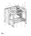
- a shelf 1 comprises a shelf 2 and a stacker crane 3.
- the shelf 2 has in the usual way a plurality of superimposed storage bins 4 for stored goods in the form of pallets 5.
- FIG. 1 only a single pallet 5 stored in the rack 2 is shown.
- the storage and retrieval unit 3 forms an arrangement for storage and retrieval of stored goods or pallets 5 on the shelf 2.
- a support and guide frame 6 performs a provided as a load conveyor lifting platform 7 of the stacker crane 3 in the vertical direction. By means of a motorized lifting drive 8, the lifting platform 7 can be raised and lowered.
- the lifting drive 8 of the storage and retrieval unit 3 comprises two electric drive motors designed as synchronous servo motors as lifting motors 9. These are mounted on the supporting and guiding frame 6 opposite one another.
- each of the hoisting motors 9 drives two drive sprockets designed as sprockets, one of which is seated on each end of the respective gear shaft 10.
- the sprockets are covered by drive housing 11 of the lifting drive 8.
- the sprockets each engage in a drive chain or lifting chain 12.
- a lifting chain 12 extends to each of the vertical columns of the support and guide frame 6. Of the four lifting chains 12 is in the FIGS. 1 and 2 to recognize one.
- the lifting chains 12 are conventional roller chain.
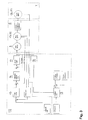
- this drive connection is in FIG. 3 illustrated.
- each of the lifting motors 9 is provided with a motor encoder 13.
- the motor encoder 13 provides information about both the actual speed of the respective lifting motor 9 as well as the vertical stroke position of the lifting platform 7, as the stroke position due to the operation of the lifting motor 9 must adjust itself. Since this theoretical stroke position of the lifting platform 7 but may differ, for example, due to a load-related elongation of the lifting chains 12 of the actual stroke position of the lifting platform 7, the lifting platform 7 is provided with a position sensor 14.
- the lifting drive 8 of the stacker crane 3 is not only used to carry out vertical conveying movements but also to realize vertical load sensing movements of the lifting platform 7. Insofar, the lifting drive 8 also forms a load detection drive.
- a detection unit 18 and an evaluation unit 19 are connected to the lifting or load sensing drive 8, in detail to the lifting drive control 20.
- the motor current is detected or measured at a converter, not shown in detail, of each lifting motor 9.
- the detected motor currents are added and compared in the evaluation unit 19 with a predetermined limit. In response to the comparison result, the lift drive controller 20 responds.
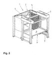
- a vertical load sensing movement is by means of the lifting drive 8 in the in FIG. 2 shown operating phase of the outsourcing of stored goods from the shelf 2 of the bearing 1 performed.
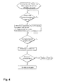
- the individual processes during the outsourcing process are in the flow chart of FIG. 4 shown.
- FIG. 4 is a pallet, in the illustrated example, the pallet 5, from the relevant storage space 4 of the shelf 2 on the stacker crane 3, in detail on the lifting platform 7, taken over.
- the relevant pallet 5 is replaced by a conventional, in FIG. 1 indicated and provided with a transfer chain transfer device 24 with a horizontal takeover movement of the respective storage space 4 of the shelf 2 is transferred to the lifting platform 7.
- the vertical load sensing movement is initiated.
- a position setpoint is stored in the lifting drive control 20.
- this position setpoint is 0.05 mm above the desired position for the lifting platform 7 when taking over the pallet 5.
- the amount of the vertical load-sensing movement is accordingly 0.05 mm. This amount is smaller than the pitch of the sprockets of the lifting drive 8. Consequently, it is ensured that the respective teeth of the sprockets with one and the same members of the lifting chains 12 are engaged during the entire load-sensing movement. Vibrations in the drive train of the lifting platform 7, as they occur in the transition from chain links of the lifting chains 12 of a tooth of the respective sprocket on another tooth ("polygon effect”) are avoided.
- the lifting motors 9 of the lifting drive 8 are set in motion and supplied with the corresponding motor current. Due to the proportionality between the motor current and the power or the force of the lifting motors 9, the motor current reflects the load of the lifting drive 8 due to the vertical load sensing movement.
- the motor current of the lifting motors 9 is measured by means of the detection unit 18.
- the measurement of the motor current is performed at a time which chronologically follows the beginning of the vertical load sensing movement.
- the measurement time is defined by means of a delay timer, which starts at the beginning of the load detection movement ( FIG. 4 ). If the predetermined delay time, in the present example 0.3 seconds, has elapsed, the measurement of the motor current is carried out.
- the time delay of the measurement compared to the beginning of the load detection movement ensures that the measurement result is not distorted by fluctuations in the motor current, which are due solely to the fact that the lifting platform 7 and the pallet 5 are transferred from the idle state to the moved state.
- the measured value acquired for the motor current is compared in a comparator of the evaluation unit 19 with a limit value stored there. If this limit is exceeded, so there is no vertical conveying movement of lift platform 7 and pallet 5. Instead, the lifting platform 7 is lowered only in that stroke position at which it has previously taken over the pallet 5. Subsequently, the pallet 5 is stored by means of the transfer device 24 of the stacker crane 3 to the relevant storage space 4 of the shelf 2 ( FIG. 4 ).
- the pallet 5 is conveyed away with a vertical conveying movement ( FIG. 4 ), ie the order for the removal of the pallet 5 is continued ( FIG. 3 ).
- FIG. 5 the temporal evolution of the motor current during the removal of the pallet 5 in a line 21 is exemplified.
- a line 22 represents the position setpoint for the lifting platform 7 during the paging process.
- the lifting platform 7 is in the vertical direction in that position in which it takes over the pallet 5.
- the line 21 for the motor current on a plurality of appreciable rashes. These rashes are due to the fact that the pallet 5 is not transferred with a uniform movement on the lifting platform 7 but rather that occasional load impacts occur, to which the Lifting drive 8 reacts with a sudden increase in the motor current.
- the lifting platform 7 has completely taken over the pallet 5 and the vertical load-sensing movement is initiated. Accordingly, the position setpoint for the lifting platform 7 develops.
- the period t 1 of the horizontal takeover movement of the pallet 5 is followed by a period t 2 of the load detection movement with a duration of 0.3 seconds.
- the limit value with which the measured value of the motor current is compared is a value which is related to the rated current of the lifting motors 9.
- the motor current at the time of the measurement amounts to approximately 60% of the rated motor current.
- This value is below the predetermined limit value (here: 75% of the rated motor current) and therefore allows the conclusion that the lifting drive 8 is not overloaded by the load to be conveyed and the pallet 5 are consequently carried away by a vertical conveying movement of the lifting platform 7 can.
- the loaded with the pallet 5 lifting platform 7 is first moved back from the raised position due to the load detection movement position in that stroke position that they had taken on acquisition of the pallet 5. Starting from this initial position then the vertical conveying movement is carried out.
- the reference numeral "25" is in FIG. 5 provided a current limit of the lifting motors 9.
- This current limit is here at 200% of the rated motor current. It serves to protect the mechanical components of the conveyor system independently of dynamic loads. Will the current limit 25 during operation the lifting motors 9 reached, they are immediately stopped. In this respect, the current limit 25 represents a safety precaution provided in addition to the load limitation described above. The limit value for the load limitation is significantly below the current limit 25.
Landscapes
- Engineering & Computer Science (AREA)
- Transportation (AREA)
- Structural Engineering (AREA)
- Mechanical Engineering (AREA)
- Civil Engineering (AREA)
- Life Sciences & Earth Sciences (AREA)
- Geology (AREA)
- Chemical & Material Sciences (AREA)
- Combustion & Propulsion (AREA)
- Warehouses Or Storage Devices (AREA)
Description
- Die Erfindung betrifft ein Verfahren zum Auslagern von Lagergut aus einem Lagerplatz eines Lagers, wobei das Lagergut mit einer horizontalen Übernahmebewegung von dem Lagerplatz auf ein Lastfördermittel übernommen wird, um anschließend gemeinsam mit dem Lastfördermittel mittels eines Hubantriebes des Lastfördermittels mit einer vertikalen Förderbewegung abgefördert zu werden.
- Die Erfindung betrifft des Weiteren eine Anordnung zum Auslagern von Lagergut aus einem Lagerplatz eines Lagers,
- mit einem Lastfördermittel, das einen Hubantrieb mit einer Hubantriebssteuerung aufweist,
- mit einer Transfervorrichtung für Lagergut,
- mit einem Lasterfassungsantrieb und einer mit dem Lasterfassungsantrieb in Verbindung stehenden Erfassungseinheit sowie
- mit einer Auswerteeinheit, die einerseits mit der Erfassungseinheit und andererseits mit der Hubantriebssteuerung in Verbindung steht,
- Ein Verfahren sowie eine Anordnung der vorstehenden Art sind bekannt aus
WO 2009/052891 A1 . Diese Druckschrift betrifft eine Fördervorrichtung mit einer Hubbühne, die einem Regallager vorgesetzt ist. Mittels eines Hubantriebes wird die Hubbühne angehoben und abgesenkt. An der Oberseite der Hubbühne ist ein Laufwagen in horizontaler Richtung entlang der Front des Regallagers verfahrbar. Zu diesem Zweck weist der Laufwagen ein Fahrgestell mit Rädern und mit die Räder lagernden Achsen auf. Als Antrieb für den Laufwagen ist eine motorische Antriebseinheit vorgesehen. An seiner Oberseite ist der Laufwagen mit einer Transfervorrichtung versehen. Die Transfervorrichtung dient dazu, mit Lagergut beladene Lagergutträger an Lagerplätzen des Regallagers einzulagern oder von den Lagerplätzen zu übernehmen. Eine motorische Antriebseinheit treibt die Lagergutträger bei deren Transfer zwischen dem Laufwagen und den Lagerplätzen an. Um einen sicheren Betrieb der Anlage zu gewährleisten, werden an den Lagergutträgern Gewichtsmessungen vorgenommen. Als Wiegeeinrichtung wird in erster Linie das Fahrgestell des Laufwagens genutzt. Anhand der Durchbiegung der Achsen des Fahrgestells wird das Gewicht des betreffenden Lagergutträgers ermittelt. Als Alternative besteht zum einen die Möglichkeit, das Gewicht des betreffenden Lagergutträgers anhand der Belastung zu ermitteln, welcher die motorische Antriebseinheit der Transfervorrichtung bei der Transferbewegung des Lagergutträgers ausgesetzt ist. Zum andern kann das Gewicht des betreffenden Lagergutträgers über die Belastung der motorischen Antriebseinheit des Laufwagens bei einer Bewegung des mit dem Lagergutträger beladenen Laufwagens längs der Hubbühne bestimmt werden. Sowohl die mittels der Transfervorrichtung bewirkten Bewegungen von Lagergutträgern als auch die Bewegungen des mit einem Lagergutträger beladenen Laufwagens längs der Hubbühne sind horizontale Bewegungen im Rahmen von übergeordneten Förderbewegungen. - Ein gattungsgemäßen Stand der Technik ist bekannt aus
JP 04-298497 A -
EP 2 062 836 A1 offenbart ein Regalbediengerät zum Auslagern von Paletten aus einem Lagerregal. Zu diesem Zweck verfährt das Regalbediengerät mit einer bühnenartigen Tragstruktur in vertikaler Richtung bis auf Höhe eines mit einer auszulagernden Palette belegten Lagerplatzes des Lagerregals. Anschließend wird die Palette von einer Transfereinrichtung des Regalbediengerätes erfasst und mit einer horizontalen Übernahmebewegung auf die bühnenartige Tragstruktur des Regalbediengerätes gezogen. Nach der Übernahme der Palette kann die bühnenartige Tragstruktur gemeinsam mit der Palette eine vertikale Förderbewegung ausführen. - Die zulässige Traglast von Regalbediengeräten der vorbekannten Art ist begrenzt. Unter Überlast ausgeführte Förderbewegungen können Mensch und Material gefährden und müssen daher verhindert werden.
- Aufgabe der vorliegenden Erfindung ist es, ein Verfahren sowie eine Vorrichtung zum Auslagern von Lagergut aus einem Lagerplatz eines Lagers bereitzustellen, im Falle derer Förderbewegungen unter Überlast und damit verbundene Gefährdungen ohne Inkaufnahme einer nennenswerten Überdimensionierung des Hubantriebes des Lastfördermittels aber gleichwohl zuverlässig ausgeschlossen sind.
- Erfindungsgemäß gelöst wird diese Aufgabe durch das Verfahren gemäß Patentanspruch 1 sowie durch die Anordnung gemäß Patentanspruch 8.
- Im Falle der Erfindung wird das auszulagernde Lagergut zunächst mit einer horizontalen Bewegung auf ein Lastfördermittel übernommen, welches dazu dienen kann, das übernommene Lagergut mit einer vertikalen Förderbewegung abzufördern. Ob die Last des Lagergutes eine derartige Förderbewegung zulässt, wird nicht - wie es an sich naheliegend wäre - während der horizontalen Übernahmebewegung sondern erst nach der Übernahme des Lagergutes durch das Lastfördermittel überprüft. Nach der Übernahme durch das Lastfördermittel wird das Lagergut gemeinsam mit dem Lastfördermittel mit einer vertikalen Lasterfassungsbewegung, d.h. mit einer speziellen Hubbewegung, bewegt. Die Belastung, die an einem zu diesem Zweck eingesetzten Lasterfassungsantrieb aufgrund der Lasterfassungsbewegung auftritt, wird erfasst und mit einer Belastungsgrenze verglichen. Die Belastung des Lasterfassungsantriebes spiegelt die Größe der in vertikaler Richtung gegebenenfalls zu fördernden Last wider. Die Belastungsgrenze wird in Abhängigkeit von der zulässigen Traglast des Lastfördermittels bzw. des Hubantriebes festgelegt. Überschreitet die festgestellte Belastung des Lasterfassungsantriebes die vorgegebene Belastungsgrenze, so unterbleibt durch entsprechende Steuerung des Hubantriebes des Lastfördermittels die an sich vorgesehene Förderbewegung. Bevorzugtermaßen wird das Lastfördermittel stattdessen nach der Lasterfassungsbewegung in diejenige vertikale Position bewegt, in welcher es zuvor das Lagergut übernommen hat, und das Lagergut wird mit einer der vorausgegangenen Übernahmebewegung entgegengerichteten Einlagerungsbewegung zu seinem ursprünglichen Lagerplatz rücküberführt. Aufgrund der erfindungsgemäßen Lastüberprüfung erübrigt sich eine nennenswerte Überdimensionierung des Hubantriebes des Lastfördermittels, wie sie bislang zur Bereitstellung von Sicherheitsreserven üblich war.
- Besondere Ausführungsarten des Verfahrens nach Patentanspruch 1 sowie der Anordnung nach Patentanspruch 8 ergeben sich aus den abhängigen Patentansprüchen 2 bis 7 und 9.
- Gemäß den Patentansprüchen 2 und 9 wird in bevorzugter Ausgestaltung der Erfindung als Lasterfassungsantrieb der Hubantrieb des Lastfördermittels genutzt. Zur Lasterfassung des Lagergutes kann eine Hubbewegung ausgeführt werden, die ihrer Art nach der beabsichtigten Förderbewegung entspricht. Komponenten des Hubantriebes können genutzt werden.
- Zur Erfassung der Belastung des Lasterfassungsantriebes, gegebenenfalls des Hubantriebes des Lastfördermittels, bieten sich erfindungsgemäß unterschiedliche Möglichkeiten. Mit einfachen technischen Mitteln und gleichwohl zuverlässig ist eine Lasterfassung dann möglich, wenn die Belastung des Lasterfassungsantriebes über die Kraft des Antriebsmotors des Lasterfassungsantriebes erfasst wird (Patentanspruch 3). Werden mehrere Antriebsmotoren eingesetzt, so ist die Kraft sämtlicher Antriebsmotoren zu ermitteln. Die sich insgesamt ergebende Kraft wird mit der vorgegebenen Belastungsgrenze verglichen,
- Für den Lasterfassungsantrieb, gegebenenfalls den Hubantrieb des Lastfördermittels, kommen unterschiedliche Antriebsbauarten in Frage. Erfindungsgemäß bevorzugt wird ein in der Praxis bewährter elektrischer Antrieb mit einem elektrischen Antriebsmotor und einem Frequenzumrichter (Patentanspruch 4). Der Motorstrom, welcher der mit einer Lasterfassungsbewegung zu hebenden Last proportional ist, kann an dem Frequenzumrichter ohne zusätzliche Stromsensoren erfasst werden.
- Aussagekräftige Informationen über die Lastverhältnisse lassen sich dann gewinnen, wenn - wie gemäß Patentanspruch 5 vorgesehen - die Lasterfassungsbewegung ausgeführt wird, nachdem das Lagergut von dem Lastfördermittel vollständig übernommen worden ist.
- Erfahrungsgemäß wird die Lasterfassungsbewegung nicht gleichförmig ausgeführt. Vielmehr treten insbesondere zu Beginn der Lasterfassungsbewegung besondere Bewegungen, beispielsweise Schwingungen des Lastfördermittels auf. Der Lasterfassungsantrieb bzw. der Hubantrieb reagiert auf derartige Erscheinungen. Vor diesem Hintergrund wird in weiterer bevorzugter Ausgestaltung der Erfindung die Belastung des Lasterfassungsantriebes, gegebenenfalls des Hubantriebes des Lastfördermittels, zu einem Zeitpunkt erfasst, welcher dem Beginn der Lasterfassungsbewegung zeitlich nachfolgt (Patentanspruch 6). Dadurch wird einer Verfremdung des Ergebnisses der Lasterfassung durch die beschriebenen Erscheinungen zu Beginn der Lasterfassungsbewegung entgegengewirkt.
- An Lasterfassungsantrieben bzw. Hubantrieben des Lastfördermittels, die zur Ausführung der Lasterfassungsbewegung eine über ein Antriebszahnrad angetriebene Antriebskette aufweisen, wird ausweislich Patentanspruch 7 der Betrag der Lasterfassungsbewegung kleiner als die Teilung der Verzahnung des Antriebszahnrades für die Antriebskette bemessen. Diese Maßnahme stellt sicher, dass sich während der Lasterfassung die gegenseitige Zuordnung der Zähne des Antriebszahnrades und der Kettenglieder der Antriebskette nicht verändert. Während der gesamten Last-erfassung sind die betreffenden Zähne des Antriebszahnrades mit denselben Kettengliedern der Antriebskette im Eingriff. Ein Übergang von Kettengliedern von einem Zahn des Antriebszahnrades auf einen anderen wird vermieden. Derartige Übergänge wären mit Erschütterungen und Schwingungen des Systems verbunden, die sich ihrerseits auf die erfasste Belastung des Lasterfassungsantriebes auswirken würden und die zur Folge hätten, dass die erfasste Belastung die aus der Last des Lagergutes resultierenden Lastverhältnisse nur bedingt widerspiegeln würde.
- Nachfolgend wird die Erfindung anhand beispielhafter schematischer Darstellungen näher erläutert. Es zeigen:
- Fig. 1
- ein Lager mit einem Regal, einem Regalbediengerät sowie einer an dem Regal eingelagerten Palette,
- Fig. 2
- die Anordnung gemäß
Figur 1 bei auf das Regalbediengerät übernommener Palette, - Fig. 3
- den Hubantrieb des Regalbediengerätes gemäß den
Figuren 1 und2 einschließlich der Hubantriebssteuerung, - Fig. 4
- den Ablaufplan für das Auslagern einer Palette an dem Lager gemäß den
Figuren 1 und2 einschließlich einer Lasterfassungsbewegung des Regalbediengerätes und - Fig. 5
- die zeitabhängige Entwicklung von Motorstrom und Lagesollwert des Hubantriebes des Regalbediengerätes gemäß den
Figuren 1 und2 beim Auslagern einer Palette. - Gemäß
Figur 1 umfasst ein Lager 1 ein Regal 2 sowie ein Regalbediengerät 3. Das Regal 2 weist in gewohnter Weise eine Mehrzahl von übereinander angeordneten Lagerplätzen 4 für Lagergut in Form von Paletten 5 auf. Der Anschaulichkeit halber ist inFigur 1 lediglich eine einzige in dem Regal 2 eingelagerte Palette 5 gezeigt. - Das Regalbediengerät 3 bildet eine Anordnung zum Ein- und Auslagern von Lagergut bzw. von Paletten 5 an dem Regal 2. Ein Trag- und Führungsgerüst 6 führt eine als Lastfördermittel vorgesehene Hubbühne 7 des Regalbediengerätes 3 in vertikaler Richtung. Mittels eines motorischen Hubantriebes 8 kann die Hubbühne 7 angehoben und abgesenkt werden.
- Der Hubantrieb 8 des Regalbediengerätes 3 umfasst zwei als Synchronservomotoren ausgeführte elektrische Antriebsmotoren als Hubmotoren 9. Diese sind an dem Trag- und Führungsgerüst 6 einander gegenüberliegend montiert.
- Über ein Getriebe mit einer Getriebewelle 10 treibt jeder der Hubmotoren 9 zwei als Kettenräder ausgebildete Antriebszahnräder an, von denen jeweils eines auf jedem Ende der betreffenden Getriebewelle 10 aufsitzt. In den
Figuren 1 und2 werden die Kettenräder durch Antriebsgehäuse 11 des Hubantriebes 8 verdeckt. - Die Kettenräder greifen jeweils in eine Antriebskette bzw. Hubkette 12 ein. Eine Hubkette 12 verläuft an jeder der vertikalen Säulen des Trag- und Führungsgerüstes 6. Von den insgesamt vier Hubketten 12 ist in den
Figuren 1 und2 eine zu erkennen. Bei den Hubketten 12 handelt es sich um herkömmliche Rollenkette. - Gemeinsam mit dem Getriebe und den Kettenrädern stellen die Hubketten 12 eine Antriebsverbindung zwischen dem jeweiligen Hubmotor 9 des Hubantriebes 8 einerseits und der Hubbühne 7 des Regalbediengerätes 3 andererseits her. Unter anderem diese Antriebsverbindung ist in
Figur 3 veranschaulicht. - Wie aus
Figur 3 außerdem hervorgeht, ist jeder der Hubmotoren 9 mit einem Motorgeber 13 versehen. Der Motorgeber 13 liefert Informationen sowohl über die Ist-Drehzahl des betreffenden Hubmotors 9 als auch über die vertikale Hublage der Hubbühne 7, so wie sich die Hublage aufgrund der Betätigung des Hubmotors 9 an sich einstellen müsse. Da diese theoretische Hublage der Hubbühne 7 aber beispielsweise aufgrund einer lastbedingten Längung der Hubketten 12 von der tatsächlichen Hublage der Hubbühne 7 abweichen kann, ist die Hubbühne 7 mit einem Lagegeber 14 versehen. - Aus der Hublageninformation des Motorgebers 13 und aus der Hublageninformation des Lagegebers 14 wird ein Mittelwert gebildet, der als Hublagen-Istwert mit einem von der numerischen Steuerung des Hubantriebes 8 vorgegebenen Lagesollwert verglichen wird. Ergibt der Ist-/Sollwertvergleich eine Lagedifferenz, so wird diese in einem Lageregler 15 mit einem Verstärkungsfaktor verstärkt. Auf der Grundlage der verstärkten Lagedifferenz wird mittels eines Geschwindigkeitsreglers 16 und eines Stromreglers 17 der Motorstrom der Hubmotoren 9 im Sinne einer Beseitigung der Lagedifferenz geregelt, Der Motorgeber 13, der Lagegeber 14, der Lageregler 15, der Geschwindigkeitsregler 16 und der Stromregler 17 sind Teil einer Hubantriebssteuerung 20. Die Hubmotoren 9 sowie die jeweils zugeordneten Getriebe, Kettenräder und Hubketten 12 bilden den Hubantrieb 8 des Regalbediengerätes 3.
- Der Hubantrieb 8 des Regalbediengerätes 3 dient nicht nur zur Ausführung vertikaler Förderbewegungen sondern auch zur Realisierung vertikaler Lasterfassungsbewegungen der Hubbühne 7. Insofern bildet der Hubantrieb 8 auch einen Lasterfassungsantrieb.
- Zu diesem Zweck sind an den Hub- bzw. Lasterfassungsantrieb 8, im Einzelnen an die Hubantriebssteuerung 20, eine Erfassungseinheit 18 sowie eine Auswerteeinheit 19 angebunden. Mittels der Erfassungseinheit 18 wird an einem nicht im Einzelnen gezeigten Umrichter eines jeden Hubmotors 9 der Motorstrom erfasste bzw. gemessen. Die erfassten Motorströme werden addiert und in der Auswerteeinheit 19 mit einem vorgegebenen Grenzwert verglichen. In Abhängigkeit von dem Vergleichsergebnis reagiert die Hubantriebssteuerung 20.
- Eine vertikale Lasterfassungsbewegung wird mittels des Hubantriebes 8 in der in
Figur 2 dargestellten Betriebsphase der Auslagerung von Lagergut aus dem Regal 2 des Lagers 1 durchgeführt. Die einzelnen Abläufe während des Auslagerungsprozesses sind in dem Ablaufplan vonFigur 4 dargestellt. - Gemäß
Figur 4 wird eine Palette, in dem dargestellten Beispielsfall die Palette 5, aus dem betreffenden Lagerplatz 4 des Regals 2 auf das Regalbediengerät 3, im Einzelnen auf dessen Hubbühne 7, übernommen. Dabei wird die betreffende Palette 5 durch eine herkömmliche, inFigur 1 angedeutete und mit einer Transferkette versehene Transfervorrichtung 24 mit einer horizontalen Übernahmebewegung von dem betreffenden Lagerplatz 4 des Regals 2 auf die Hubbühne 7 transferiert. Nachdem die Palette 5 von der Hubbühne 7 vollständig übernommen worden ist (Figur 2 ) und die horizontale Palettenbewegung dementsprechend beendet ist (Figur 4 ), wird die vertikale Lasterfassungsbewegung eingeleitet. - Für die vertikale Lasterfassungsbewegung ist in der Hubantriebssteuerung 20 ein Lagesollwert hinterlegt. Im gezeigten Beispielsfall liegt dieser Lagesollwert 0,05mm über dem Lagesollwert für die Hubbühne 7 bei der Übernahme der Palette 5. Der Betrag der vertikalen Lasterfassungsbewegung beläuft sich dementsprechend auf 0,05mm. Dieser Betrag ist kleiner als die Teilung der Kettenräder des Hubantriebes 8. Folglich ist sichergestellt, dass sich während der gesamten Lasterfassungsbewegung die betreffenden Zähne der Kettenräder mit ein und denselben Gliedern der Hubketten 12 im Eingriff befinden. Erschütterungen im Antriebsstrang der Hubbühne 7, wie sie bei dem Übergang von Kettengliedern der Hubketten 12 von einem Zahn des betreffenden Kettenrades auf einen anderen Zahn auftreten ("Polygoneffekt"), werden vermieden.
- Um die mit der Palette 5 beladene Hubbühne 7 in eine dem Lagesollwert der vertikalen Lasterfassungsbewegung entsprechende Hublage zu überführen, werden die Hubmotoren 9 des Hubantriebes 8 in Gang gesetzt und mit dem entsprechenden Motorstrom versorgt. Aufgrund der Proportionalität zwischen dem Motorstrom und der Leistung bzw. der Kraft der Hubmotoren 9 spiegelt der Motorstrom die Belastung des Hubantriebes 8 aufgrund der vertikalen Lasterfassungsbewegung wider.
- Der Motorstrom der Hubmotoren 9 wird mittels der Erfassungseinheit 18 gemessen. Die Messung des Motorstromes wird zu einem Zeitpunkt durchgeführt, welcher dem Beginn der vertikalen Lasterfassungsbewegung zeitlich nachfolgt.
- Der Messzeitpunkt wird mittels eines Verzögerungstimers definiert, der mit Beginn der Lasterfassungsbewegung startet (
Figur 4 ). Ist die vorgegebene Verzögerungszeit, in dem vorliegenden Beispielsfall 0,3 Sekunden, abgelaufen, so wird die Messung des Motorstromes durchgeführt. Durch die zeitliche Verzögerung der Messung gegenüber dem Beginn der Lasterfassungsbewegung wird sichergestellt, dass das Messergebnis nicht durch Schwankungen des Motorstroms verfremdet wird, die allein darauf zurückzuführen sind, dass die Hubbühne 7 und die Palette 5 aus dem Ruhezustand in den bewegten Zustand überführt werden. - Der für den Motorstrom erfasste Messwert wird in einem Komparator der Auswerteeinheit 19 mit einem dort hinterlegten Grenzwert verglichen. Wird dieser Grenzwert überschritten, so unterbleibt eine vertikale Förderbewegung von Hubbühne 7 und Palette 5. Stattdessen wird die Hubbühne 7 lediglich in diejenige Hublage abgesenkt, bei welcher sie zuvor die Palette 5 übernommen hat. Anschließend wird die Palette 5 mittels der Übernahmevorrichtung 24 des Regalbediengerätes 3 auf den betreffenden Lagerplatz 4 des Regals 2 rückgelagert (
Figur 4 ). - Wird der Grenzwert des Motorstromes durch den Messwert nicht überschritten, so wird die Palette 5 mit einer vertikalen Förderbewegung abgefördert (
Figur 4 ), d.h. der Auftrag zur Auslagerung der Palette 5 wird fortgesetzt (Figur 3 ). - In
Figur 5 ist die zeitliche Entwicklung des Motorstroms während des Auslagerns der Palette 5 in einer Linie 21 beispielhaft veranschaulicht. Eine Linie 22 stellt den Lagesollwert für die Hubbühne 7 während des Auslagerungsprozesses dar. - Während eines Zeitraums t1 befindet sich die Hubbühne 7 in vertikaler Richtung in derjenigen Position, in welcher sie die Palette 5 übernimmt. Während dieser Zeit weist die Linie 21 für den Motorstrom eine Mehrzahl nennenswerter Ausschläge auf. Diese Ausschläge sind darauf zurückzuführen, dass die Palette 5 nicht mit einer gleichförmigen Bewegung auf die Hubbühne 7 transferiert wird sondern dass vielmehr gelegentliche Belastungsschläge auftreten, auf welche der Hubantrieb 8 mit einer schlagartigen Erhöhung des Motorstroms reagiert. Am Ende des Zeitraums t1 hat die Hubbühne 7 die Palette 5 vollständig übernommen und die vertikale Lasterfassungsbewegung wird eingeleitet. Dementsprechend entwickelt sich der Lagesollwert für die Hubbühne 7. Auf den Zeitraum t1 der horizontalen Übernahmebewegung der Palette 5 folgt ein Zeitraum t2 der Lasterfassungsbewegung mit einer Dauer von 0,3 Sekunden.
- Erst gegen Ende des Zeitraums t2 wird derjenige Messwert des Motorstroms bestimmt, welcher mit dem vorgegebenen Grenzwert zu vergleichen ist. Gemäß
Figur 5 hat sich der Motorstrom zu dem Messzeitpunkt nach vorausgegangenen, auf die Änderung des Bewegungszustandes der Hubbühne 7 mit der Palette 5 zurückzuführenden Ausschläge wieder beruhigt. Infolgedessen gibt der ermittelte Messwert die Belastungsverhältnisse des Hubantriebes 8 exakt wieder. Der Messzeitpunkt wird inFigur 5 durch einen Punkt 23 der Linie 21 des Motorstroms markiert. - Bei dem Grenzwert, mit welchem der Messwert des Motorstroms verglichen wird, handelt es sich um einen Wert, der auf den Nennstrom der Hubmotoren 9 bezogen ist. Im dargestellten Beispiel beläuft sich der Motorstrom zum Zeitpunkt der Messung auf rund 60% des Motor-Nennstroms. Dieser Wert liegt unterhalb des vorgegebenen Grenzwertes (hier: 75% des Motor-Nennstroms) und lässt daher den Rückschluss zu, dass der Hubantrieb 8 durch die zu fördernde Last nicht überlastet wird und die Palette 5 folglich durch eine vertikale Förderbewegung der Hubbühne 7 abgefördert werden kann. Zu diesem Zweck wird die mit der Palette 5 beladene Hubbühne 7 zunächst aus der aufgrund der Lasterfassungbewegung angehobenen Position in diejenige Hublage zurückbewegt, die sie bei Übernahme der Palette 5 eingenommen hatte. Ausgehend von dieser Anfangsposition wird dann die vertikale Förderbewegung ausgeführt.
- Mit dem Bezugszeichen "25" ist in
Figur 5 eine Stromgrenze der Hubmotoren 9 versehen. Diese Stromgrenze liegt hier bei 200% des Motor-Nennstroms. Sie dient zum Schutz der mechanischen Komponenten der Förderanlage unabhängig von dynamischen Belastungen. Wird die Stromgrenze 25 während des Betriebs der Hubmotoren 9 erreicht, so werden diese unmittelbar stillgesetzt. Insofern stellt die Stromgrenze 25 eine zusätzlich zu der vorstehend beschriebenen Lastbegrenzung vorgesehene Sicherheitsvorkehrung dar. Der Grenzwert für die Lastbegrenzung liegt deutlich unter der Stromgrenze 25.
Claims (9)
- Verfahren zum Auslagern von Lagergut (5) aus einem Lagerplatz (4) eines Lagers (1), wobei das Lagergut (5) mit einer horizontalen Übernahmebewegung von dem Lagerplatz (4) auf ein Lastfördermittel (7) übernommen wird, um anschließend gemeinsam mit dem Lastfördermittel (7) mittels eines Hubantriebes (8) des Lastfördermittels (7) mit einer vertikalen Förderbewegung abgefördert zu werden,
dadurch gekennzeichnet,• dass das Lagergut (5) nach der Übernahme durch das Lastfördermittel (7) gemeinsam mit dem Lastfördermittel (7) mittels eines Lasterfassungsantriebes mit einer vertikalen Lasterfassungsbewegung bewegt wird,• dass die aufgrund der vertikalen Lasterfassungsbewegung auftretende Belastung des Lasterfassungsantriebes erfasst und mit einer Belastungsgrenze verglichen wird und• dass die Förderbewegung von Lagergut (5) und Lastfördermittel (7) nur dann ausgeführt wird, wenn die aufgrund der vertikalen Lasterfassungsbewegung aufgetretene Belastung des Lasterfassungsantriebes die Belastungsgrenze nicht überschreitet. - Verfahren nach Anspruch 1, dadurch gekennzeichnet, dass die Lasterfassungsbewegung mittels des als Lasterfassungsantrieb vorgesehenen Hubantriebes (8) des Lastfördermittels (7) ausgeführt wird.
- Verfahren nach Anspruch 1 oder 2, dadurch gekennzeichnet, dass der Lasterfassungsantrieb, gegebenenfalls der Hubantrieb (8) des Lastfördermittels (7), einen Antriebsmotor (9) aufweist und dass die aufgrund der Lasterfassungsbewegung auftretende Belastung des Lasterfassungsantriebes, gegebenenfalls des Hubantriebes (8) des Lastfördermittels (7), über die Kraft des Antriebsmotors (9) aufgrund der Lasterfassungsbewegung erfasst wird.
- Verfahren nach einem der Ansprüche 1 bis 3, dadurch gekennzeichnet, dass der Lasterfassungsantrieb, gegebenenfalls der Hubantrieb (8) des Lastfördermittels (7), als Antriebsmotor (9) einen elektrischen Antriebsmotor mit einem Frequenzumrichter aufweist und dass die Kraft des elektrischen Antriebsmotors (9) über dessen Stromaufnahme an dem Frequenzumrichter erfasst wird.
- Verfahren nach einem der Ansprüche 1 bis 4, dadurch gekennzeichnet, dass die Lasterfassungsbewegung ausgeführt wird, nachdem das Lagergut (5) von dem Lastfördermittel (7) vollständig übernommen worden ist.
- Verfahren nach einem der Ansprüche 1 bis 5, dadurch gekennzeichnet, dass die Belastung des Lasterfassungsantriebes, gegebenenfalls des Hubantriebes (8) des Lastfördermittels (7), zu einem Zeitpunkt erfasst wird, welcher dem Beginn der Lasterfassungsbewegung zeitlich nachfolgt.
- Verfahren nach einem der Ansprüche 1 bis 6, dadurch gekennzeichnet, dass der Lasterfassungsantrieb, gegebenenfalls der Hubantrieb (8) des Lastfördermittels (7), eine Antriebskette (12) aufweist, die zur Ausführung der Lasterfassungsbewegung mittels eines Antriebsmotors (9) über ein Antriebszahnrad angetrieben wird und dass die Lasterfassungsbewegung mit einem Betrag ausgeführt wird, der kleiner ist als die Teilung des Antriebszahnrades der Antriebskette (12).
- Anordnung zum Auslagern von Lagergut (5) aus einem Lagerplatz (4) eines Lagers (1),• mit einem Lastfördermittel (7), das einen Hubantrieb (8) mit einer Hubantriebssteuerung (20) aufweist,• mit einer Transfervorrichtung (24) für Lagergut (5),• mit einem Lasterfassungsantrieb und einer mit dem Lasterfassungsantrieb in Verbindung stehenden Erfassungseinheit (18) sowie• mit einer Auswerteeinheit (19), die einerseits mit der Erfassungseinheit (18) und andererseits mit der Hubantriebssteuerung (20) in Verbindung steht,wobei die Transfervorrichtung (24) das Lagergut mit einer horizontalen Übernahmebewegung von dem Lagerplatz (4) auf das Lastfördermittel (7) übernimmt und wobei der Hubantrieb (8) des Lastfördermittels (7) das von dem Lastfördermittel (7) übernommene Lagergut (5) gemeinsam mit dem Lastfördermittel (7) mit einer vertikalen Förderbewegung abfördert,
dadurch gekennzeichnet,• dass der Lasterfassungsantrieb das von dem Lastfördermittel (7) übernommene Lagergut (5) gemeinsam mit dem Lastfördermittel (7) mit einer vertikalen Lasterfassungsbewegung bewegt,• dass die Erfassungseinheit (18) die aufgrund der vertikalen Lasterfassungsbewegung auftretende Belastung des Lasterfassungsantriebes erfasst,• dass die Auswerteeinheit (19) diese Belastung mit einer Belastungsgrenze vergleicht und• dass die Hubantriebssteuerung (20) den Hubantrieb (8) des Lastfördermittels (7) nur dann im Sinne der Ausführung einer Förderbewegung steuert, wenn die aufgrund der vertikalen Lasterfassungsbewegung aufgetretene Belastung des Lasterfassungsantriebes die Belastungsgrenze nicht überschreitet. - Anordnung nach Anspruch 8, dadurch gekennzeichnet dass als Lasterfassungsantrieb der Hubantrieb (8) des Lastfördermittels (7) vorgesehen ist.
Applications Claiming Priority (1)
| Application Number | Priority Date | Filing Date | Title |
|---|---|---|---|
| DE102010028392A DE102010028392A1 (de) | 2010-04-29 | 2010-04-29 | Verfahren und Anordnung zum Auslagern von Lagergut aus einem Lagerplatz eines Lagers |
Publications (2)
| Publication Number | Publication Date |
|---|---|
| EP2383208A1 EP2383208A1 (de) | 2011-11-02 |
| EP2383208B1 true EP2383208B1 (de) | 2012-12-26 |
Family
ID=44351806
Family Applications (1)
| Application Number | Title | Priority Date | Filing Date |
|---|---|---|---|
| EP20110162413 Active EP2383208B1 (de) | 2010-04-29 | 2011-04-14 | Verfahren und Anordnung zum Auslagern von Lagergut aus einem Lagerplatz eines Lagers |
Country Status (3)
| Country | Link |
|---|---|
| EP (1) | EP2383208B1 (de) |
| JP (1) | JP5794821B2 (de) |
| DE (1) | DE102010028392A1 (de) |
Families Citing this family (3)
| Publication number | Priority date | Publication date | Assignee | Title |
|---|---|---|---|---|
| DE102018120081B4 (de) * | 2018-08-17 | 2021-06-17 | Khs Gmbh | Behälterreinigungsmaschine |
| CN111994829B (zh) * | 2020-08-26 | 2022-02-22 | 广东博智林机器人有限公司 | 一种载货台及堆垛机 |
| JP7816290B2 (ja) * | 2023-05-31 | 2026-02-18 | トヨタ自動車株式会社 | 搬送システム |
Family Cites Families (12)
| Publication number | Priority date | Publication date | Assignee | Title |
|---|---|---|---|---|
| JPS5653420A (en) * | 1979-10-08 | 1981-05-13 | Daihen Corp | Measuring device of crane |
| JPH04298497A (ja) * | 1991-03-23 | 1992-10-22 | Yamazaki Mazak Corp | 立体自動倉庫におけるクレーンの事故防止装置 |
| JPH07285798A (ja) * | 1994-04-21 | 1995-10-31 | Toyo Umpanki Co Ltd | 荷役装置 |
| DE19511591C2 (de) * | 1995-03-29 | 1997-02-06 | Jungheinrich Ag | Verfahren zur Bestimmung der Last eines Flurförderzeugs |
| DE19918039A1 (de) * | 1999-04-21 | 2000-10-26 | Steinbock Boss Gmbh Foerdertec | Hydraulische Lastenhubvorrichtung, insbesondere für ein Flurförderzeug |
| DE29909604U1 (de) * | 1999-06-05 | 1999-10-28 | Potthast, Fritz, 48165 Münster | Automatisiertes Lager-System für kurze und/oder mittlere oder lange Lagergüter, vorzugsweise für marktgängige, in ihren Abmessungen auch voneinander abweichende Paletten und/oder Container |
| DE10347730A1 (de) * | 2003-10-14 | 2005-05-12 | Still Wagner Gmbh & Co Kg | Hochregalflurförderzeug mit einem anhebbaren Fahrkorb |
| UA82679C2 (uk) * | 2005-06-03 | 2008-05-12 | Олег Борисович Бендарик | Спосіб та пристрій для визначення ваги вантажу |
| DE102006037719B4 (de) * | 2006-08-03 | 2009-07-02 | SSI Schäfer Noell GmbH Lager- und Systemtechnik | Regalbediengerät |
| US20110020098A1 (en) * | 2007-10-26 | 2011-01-27 | Bernd Pfaffmann | Storage rack with loading management |
| RU2354604C1 (ru) * | 2007-11-06 | 2009-05-10 | Государственное образовательное учреждение высшего профессионального образования "Томский государственный архитектурно-строительный университет" (ГОУВПО "ТГАСУ") | Способ ограничения грузоподъемности крана мостового типа |
| EP2062836B1 (de) | 2007-11-26 | 2009-07-22 | Trumpf Sachsen GmbH | Verfahren zum Auslagern, Verfahren zum Einlagern und Verfahren zum Handling von Lagergut an einem Lager sowie Lageranordnungen zur Realisierung der genannten Verfahren |
-
2010
- 2010-04-29 DE DE102010028392A patent/DE102010028392A1/de not_active Withdrawn
-
2011
- 2011-04-14 EP EP20110162413 patent/EP2383208B1/de active Active
- 2011-04-26 JP JP2011097780A patent/JP5794821B2/ja active Active
Also Published As
| Publication number | Publication date |
|---|---|
| JP2011230928A (ja) | 2011-11-17 |
| DE102010028392A1 (de) | 2011-11-03 |
| EP2383208A1 (de) | 2011-11-02 |
| JP5794821B2 (ja) | 2015-10-14 |
Similar Documents
| Publication | Publication Date | Title |
|---|---|---|
| EP3183190B1 (de) | Lager- und/oder kommissioniersysteme | |
| EP2609021B1 (de) | Lagerregalsystem zur lagerung von lagergut | |
| EP1140670B1 (de) | Verfahren und lagersystem zum ein- und auslagern von lasten | |
| EP2648997B1 (de) | Universelles lastaufnahmemittel für palettenlose handhabung von paletten-ladegütern | |
| DE102011106677B4 (de) | System und Verfahren zum Ein- und Auslagern eines Lagerguts in ein und aus einem Regal | |
| DE69208673T2 (de) | Vorrichtung und verfahren zum lagern von produkten | |
| EP3064466A1 (de) | Fahrwagen für ein palettenhandhabungssystem | |
| AT506918B1 (de) | Aufnahmevorrichtung für ein förderfahrzeug | |
| EP2539248A1 (de) | Lastaufnahmevorrichtung für ein regalbediengerät, regalbediengerät und lagersystem | |
| EP1446353B1 (de) | Lastaufnahmemittel zur verwendung in einem system zum bedienen von lagereinheiten | |
| DE102015000968A1 (de) | Mobiles Nachschubregal mit Regalbediengerät | |
| EP1478584B1 (de) | Regalbediengerät mit einem lastaufnahmemittel | |
| WO2016066182A1 (de) | Hubmechanismus, kanalfahrzeug und hubvorrichtung mit einem hubmechanismus sowie lagersystem | |
| DE69303173T2 (de) | Regalbedienungsgrät mit gabeln dopplter reichweite | |
| EP2062836B1 (de) | Verfahren zum Auslagern, Verfahren zum Einlagern und Verfahren zum Handling von Lagergut an einem Lager sowie Lageranordnungen zur Realisierung der genannten Verfahren | |
| EP2383208A1 (de) | Verfahren und Anordnung zum Auslagern von Lagergut aus einem Lagerplatz eines Lagers | |
| DE102015115323A1 (de) | Regalbediengerät | |
| EP4053054A1 (de) | Vorrichtung und verfahren zum kommissionieren von ladegut | |
| DE102006037719B4 (de) | Regalbediengerät | |
| DE9218776U1 (de) | Lagervorrichtung zur Lagerung von Produkten oder Gegenständen | |
| DE10021694A1 (de) | Verfahren zum Ein- und Auslagern von Lasten und Transportvorrichtung zum Einsatz in einem Regallager | |
| EP2502872A1 (de) | Regalbediengeraät | |
| DE202011110666U1 (de) | Regalbediengerät | |
| AT522924A1 (de) | Regalbediengerät und automatisches Kleinteillager | |
| DE4130137A1 (de) | Hochregallager mit mindestens einer regalreihe und mit einer horizontal und mittels einer hubeinrichtung vertikal entlang der regalreihe verschiebbare vorrichtung zum ein- und ausbringen von zu lagernden gegenstaenden, wie paletten, koerben, kisten, kassetten o. dgl. |
Legal Events
| Date | Code | Title | Description |
|---|---|---|---|
| AK | Designated contracting states |
Kind code of ref document: A1 Designated state(s): AL AT BE BG CH CY CZ DE DK EE ES FI FR GB GR HR HU IE IS IT LI LT LU LV MC MK MT NL NO PL PT RO RS SE SI SK SM TR |
|
| AX | Request for extension of the european patent |
Extension state: BA ME |
|
| PUAI | Public reference made under article 153(3) epc to a published international application that has entered the european phase |
Free format text: ORIGINAL CODE: 0009012 |
|
| 17P | Request for examination filed |
Effective date: 20120329 |
|
| RAP1 | Party data changed (applicant data changed or rights of an application transferred) |
Owner name: TRUMPF SACHSEN GMBH |
|
| GRAP | Despatch of communication of intention to grant a patent |
Free format text: ORIGINAL CODE: EPIDOSNIGR1 |
|
| RIC1 | Information provided on ipc code assigned before grant |
Ipc: B66F 9/07 20060101ALI20120612BHEP Ipc: B66F 17/00 20060101ALI20120612BHEP Ipc: G01G 19/18 20060101ALI20120612BHEP Ipc: B65G 1/04 20060101AFI20120612BHEP Ipc: B66F 9/24 20060101ALI20120612BHEP Ipc: B66D 1/58 20060101ALI20120612BHEP |
|
| GRAS | Grant fee paid |
Free format text: ORIGINAL CODE: EPIDOSNIGR3 |
|
| GRAA | (expected) grant |
Free format text: ORIGINAL CODE: 0009210 |
|
| AK | Designated contracting states |
Kind code of ref document: B1 Designated state(s): AL AT BE BG CH CY CZ DE DK EE ES FI FR GB GR HR HU IE IS IT LI LT LU LV MC MK MT NL NO PL PT RO RS SE SI SK SM TR |
|
| REG | Reference to a national code |
Ref country code: GB Ref legal event code: FG4D Free format text: NOT ENGLISH |
|
| REG | Reference to a national code |
Ref country code: CH Ref legal event code: EP |
|
| REG | Reference to a national code |
Ref country code: AT Ref legal event code: REF Ref document number: 590309 Country of ref document: AT Kind code of ref document: T Effective date: 20130115 |
|
| REG | Reference to a national code |
Ref country code: DE Ref legal event code: R096 Ref document number: 502011000311 Country of ref document: DE Effective date: 20130307 |
|
| PG25 | Lapsed in a contracting state [announced via postgrant information from national office to epo] |
Ref country code: LT Free format text: LAPSE BECAUSE OF FAILURE TO SUBMIT A TRANSLATION OF THE DESCRIPTION OR TO PAY THE FEE WITHIN THE PRESCRIBED TIME-LIMIT Effective date: 20121226 Ref country code: SE Free format text: LAPSE BECAUSE OF FAILURE TO SUBMIT A TRANSLATION OF THE DESCRIPTION OR TO PAY THE FEE WITHIN THE PRESCRIBED TIME-LIMIT Effective date: 20121226 Ref country code: NO Free format text: LAPSE BECAUSE OF FAILURE TO SUBMIT A TRANSLATION OF THE DESCRIPTION OR TO PAY THE FEE WITHIN THE PRESCRIBED TIME-LIMIT Effective date: 20130326 Ref country code: HR Free format text: LAPSE BECAUSE OF FAILURE TO SUBMIT A TRANSLATION OF THE DESCRIPTION OR TO PAY THE FEE WITHIN THE PRESCRIBED TIME-LIMIT Effective date: 20121226 |
|
| REG | Reference to a national code |
Ref country code: LT Ref legal event code: MG4D |
|
| REG | Reference to a national code |
Ref country code: NL Ref legal event code: VDEP Effective date: 20121226 |
|
| PG25 | Lapsed in a contracting state [announced via postgrant information from national office to epo] |
Ref country code: SI Free format text: LAPSE BECAUSE OF FAILURE TO SUBMIT A TRANSLATION OF THE DESCRIPTION OR TO PAY THE FEE WITHIN THE PRESCRIBED TIME-LIMIT Effective date: 20121226 Ref country code: GR Free format text: LAPSE BECAUSE OF FAILURE TO SUBMIT A TRANSLATION OF THE DESCRIPTION OR TO PAY THE FEE WITHIN THE PRESCRIBED TIME-LIMIT Effective date: 20130327 Ref country code: LV Free format text: LAPSE BECAUSE OF FAILURE TO SUBMIT A TRANSLATION OF THE DESCRIPTION OR TO PAY THE FEE WITHIN THE PRESCRIBED TIME-LIMIT Effective date: 20121226 |
|
| PG25 | Lapsed in a contracting state [announced via postgrant information from national office to epo] |
Ref country code: ES Free format text: LAPSE BECAUSE OF FAILURE TO SUBMIT A TRANSLATION OF THE DESCRIPTION OR TO PAY THE FEE WITHIN THE PRESCRIBED TIME-LIMIT Effective date: 20130406 Ref country code: EE Free format text: LAPSE BECAUSE OF FAILURE TO SUBMIT A TRANSLATION OF THE DESCRIPTION OR TO PAY THE FEE WITHIN THE PRESCRIBED TIME-LIMIT Effective date: 20121226 Ref country code: IS Free format text: LAPSE BECAUSE OF FAILURE TO SUBMIT A TRANSLATION OF THE DESCRIPTION OR TO PAY THE FEE WITHIN THE PRESCRIBED TIME-LIMIT Effective date: 20130426 Ref country code: BG Free format text: LAPSE BECAUSE OF FAILURE TO SUBMIT A TRANSLATION OF THE DESCRIPTION OR TO PAY THE FEE WITHIN THE PRESCRIBED TIME-LIMIT Effective date: 20130326 Ref country code: SK Free format text: LAPSE BECAUSE OF FAILURE TO SUBMIT A TRANSLATION OF THE DESCRIPTION OR TO PAY THE FEE WITHIN THE PRESCRIBED TIME-LIMIT Effective date: 20121226 Ref country code: RS Free format text: LAPSE BECAUSE OF FAILURE TO SUBMIT A TRANSLATION OF THE DESCRIPTION OR TO PAY THE FEE WITHIN THE PRESCRIBED TIME-LIMIT Effective date: 20121226 |
|
| PG25 | Lapsed in a contracting state [announced via postgrant information from national office to epo] |
Ref country code: PL Free format text: LAPSE BECAUSE OF FAILURE TO SUBMIT A TRANSLATION OF THE DESCRIPTION OR TO PAY THE FEE WITHIN THE PRESCRIBED TIME-LIMIT Effective date: 20121226 Ref country code: RO Free format text: LAPSE BECAUSE OF FAILURE TO SUBMIT A TRANSLATION OF THE DESCRIPTION OR TO PAY THE FEE WITHIN THE PRESCRIBED TIME-LIMIT Effective date: 20121226 Ref country code: PT Free format text: LAPSE BECAUSE OF FAILURE TO SUBMIT A TRANSLATION OF THE DESCRIPTION OR TO PAY THE FEE WITHIN THE PRESCRIBED TIME-LIMIT Effective date: 20130426 Ref country code: NL Free format text: LAPSE BECAUSE OF FAILURE TO SUBMIT A TRANSLATION OF THE DESCRIPTION OR TO PAY THE FEE WITHIN THE PRESCRIBED TIME-LIMIT Effective date: 20121226 |
|
| BERE | Be: lapsed |
Owner name: TRUMPF SACHSEN G.M.B.H. Effective date: 20130430 |
|
| PG25 | Lapsed in a contracting state [announced via postgrant information from national office to epo] |
Ref country code: DK Free format text: LAPSE BECAUSE OF FAILURE TO SUBMIT A TRANSLATION OF THE DESCRIPTION OR TO PAY THE FEE WITHIN THE PRESCRIBED TIME-LIMIT Effective date: 20121226 |
|
| PLBE | No opposition filed within time limit |
Free format text: ORIGINAL CODE: 0009261 |
|
| STAA | Information on the status of an ep patent application or granted ep patent |
Free format text: STATUS: NO OPPOSITION FILED WITHIN TIME LIMIT |
|
| PG25 | Lapsed in a contracting state [announced via postgrant information from national office to epo] |
Ref country code: CY Free format text: LAPSE BECAUSE OF FAILURE TO SUBMIT A TRANSLATION OF THE DESCRIPTION OR TO PAY THE FEE WITHIN THE PRESCRIBED TIME-LIMIT Effective date: 20121226 Ref country code: MC Free format text: LAPSE BECAUSE OF FAILURE TO SUBMIT A TRANSLATION OF THE DESCRIPTION OR TO PAY THE FEE WITHIN THE PRESCRIBED TIME-LIMIT Effective date: 20121226 |
|
| 26N | No opposition filed |
Effective date: 20130927 |
|
| REG | Reference to a national code |
Ref country code: DE Ref legal event code: R097 Ref document number: 502011000311 Country of ref document: DE Effective date: 20130927 |
|
| REG | Reference to a national code |
Ref country code: IE Ref legal event code: MM4A |
|
| PG25 | Lapsed in a contracting state [announced via postgrant information from national office to epo] |
Ref country code: BE Free format text: LAPSE BECAUSE OF NON-PAYMENT OF DUE FEES Effective date: 20130430 |
|
| REG | Reference to a national code |
Ref country code: FR Ref legal event code: ST Effective date: 20131231 |
|
| PG25 | Lapsed in a contracting state [announced via postgrant information from national office to epo] |
Ref country code: FR Free format text: LAPSE BECAUSE OF NON-PAYMENT OF DUE FEES Effective date: 20130430 |
|
| PG25 | Lapsed in a contracting state [announced via postgrant information from national office to epo] |
Ref country code: IE Free format text: LAPSE BECAUSE OF NON-PAYMENT OF DUE FEES Effective date: 20130414 |
|
| PG25 | Lapsed in a contracting state [announced via postgrant information from national office to epo] |
Ref country code: MT Free format text: LAPSE BECAUSE OF FAILURE TO SUBMIT A TRANSLATION OF THE DESCRIPTION OR TO PAY THE FEE WITHIN THE PRESCRIBED TIME-LIMIT Effective date: 20121226 |
|
| PG25 | Lapsed in a contracting state [announced via postgrant information from national office to epo] |
Ref country code: SM Free format text: LAPSE BECAUSE OF FAILURE TO SUBMIT A TRANSLATION OF THE DESCRIPTION OR TO PAY THE FEE WITHIN THE PRESCRIBED TIME-LIMIT Effective date: 20121226 |
|
| PG25 | Lapsed in a contracting state [announced via postgrant information from national office to epo] |
Ref country code: TR Free format text: LAPSE BECAUSE OF FAILURE TO SUBMIT A TRANSLATION OF THE DESCRIPTION OR TO PAY THE FEE WITHIN THE PRESCRIBED TIME-LIMIT Effective date: 20121226 |
|
| PG25 | Lapsed in a contracting state [announced via postgrant information from national office to epo] |
Ref country code: HU Free format text: LAPSE BECAUSE OF FAILURE TO SUBMIT A TRANSLATION OF THE DESCRIPTION OR TO PAY THE FEE WITHIN THE PRESCRIBED TIME-LIMIT; INVALID AB INITIO Effective date: 20110414 Ref country code: LU Free format text: LAPSE BECAUSE OF NON-PAYMENT OF DUE FEES Effective date: 20130414 Ref country code: MK Free format text: LAPSE BECAUSE OF FAILURE TO SUBMIT A TRANSLATION OF THE DESCRIPTION OR TO PAY THE FEE WITHIN THE PRESCRIBED TIME-LIMIT Effective date: 20121226 |
|
| GBPC | Gb: european patent ceased through non-payment of renewal fee |
Effective date: 20150414 |
|
| PG25 | Lapsed in a contracting state [announced via postgrant information from national office to epo] |
Ref country code: GB Free format text: LAPSE BECAUSE OF NON-PAYMENT OF DUE FEES Effective date: 20150414 |
|
| REG | Reference to a national code |
Ref country code: AT Ref legal event code: MM01 Ref document number: 590309 Country of ref document: AT Kind code of ref document: T Effective date: 20160414 |
|
| PG25 | Lapsed in a contracting state [announced via postgrant information from national office to epo] |
Ref country code: AT Free format text: LAPSE BECAUSE OF NON-PAYMENT OF DUE FEES Effective date: 20160414 |
|
| PG25 | Lapsed in a contracting state [announced via postgrant information from national office to epo] |
Ref country code: AL Free format text: LAPSE BECAUSE OF FAILURE TO SUBMIT A TRANSLATION OF THE DESCRIPTION OR TO PAY THE FEE WITHIN THE PRESCRIBED TIME-LIMIT Effective date: 20121226 |
|
| REG | Reference to a national code |
Ref country code: DE Ref legal event code: R082 Ref document number: 502011000311 Country of ref document: DE Representative=s name: PROBST, MATTHIAS, DE Ref country code: DE Ref legal event code: R081 Ref document number: 502011000311 Country of ref document: DE Owner name: TRUMPF SACHSEN SE, DE Free format text: FORMER OWNER: TRUMPF SACHSEN GMBH, 01904 NEUKIRCH, DE |
|
| PGFP | Annual fee paid to national office [announced via postgrant information from national office to epo] |
Ref country code: FI Payment date: 20250424 Year of fee payment: 15 |
|
| PGFP | Annual fee paid to national office [announced via postgrant information from national office to epo] |
Ref country code: DE Payment date: 20250422 Year of fee payment: 15 |
|
| PGFP | Annual fee paid to national office [announced via postgrant information from national office to epo] |
Ref country code: IT Payment date: 20250424 Year of fee payment: 15 |
|
| PGFP | Annual fee paid to national office [announced via postgrant information from national office to epo] |
Ref country code: CH Payment date: 20250501 Year of fee payment: 15 |
|
| PGFP | Annual fee paid to national office [announced via postgrant information from national office to epo] |
Ref country code: CZ Payment date: 20250404 Year of fee payment: 15 |
|
| REG | Reference to a national code |
Ref country code: CH Ref legal event code: U11 Free format text: ST27 STATUS EVENT CODE: U-0-0-U10-U11 (AS PROVIDED BY THE NATIONAL OFFICE) Effective date: 20260501 |