EP2378232B1 - Bent micro-channel heat exchanger - Google Patents
Bent micro-channel heat exchanger Download PDFInfo
- Publication number
- EP2378232B1 EP2378232B1 EP11002997.2A EP11002997A EP2378232B1 EP 2378232 B1 EP2378232 B1 EP 2378232B1 EP 11002997 A EP11002997 A EP 11002997A EP 2378232 B1 EP2378232 B1 EP 2378232B1
- Authority
- EP
- European Patent Office
- Prior art keywords
- bent
- heat exchanger
- micro
- channel heat
- segment
- Prior art date
- Legal status (The legal status is an assumption and is not a legal conclusion. Google has not performed a legal analysis and makes no representation as to the accuracy of the status listed.)
- Active
Links
Images


Classifications
-
- F—MECHANICAL ENGINEERING; LIGHTING; HEATING; WEAPONS; BLASTING
- F28—HEAT EXCHANGE IN GENERAL
- F28D—HEAT-EXCHANGE APPARATUS, NOT PROVIDED FOR IN ANOTHER SUBCLASS, IN WHICH THE HEAT-EXCHANGE MEDIA DO NOT COME INTO DIRECT CONTACT
- F28D1/00—Heat-exchange apparatus having stationary conduit assemblies for one heat-exchange medium only, the media being in contact with different sides of the conduit wall, in which the other heat-exchange medium is a large body of fluid, e.g. domestic or motor car radiators
- F28D1/02—Heat-exchange apparatus having stationary conduit assemblies for one heat-exchange medium only, the media being in contact with different sides of the conduit wall, in which the other heat-exchange medium is a large body of fluid, e.g. domestic or motor car radiators with heat-exchange conduits immersed in the body of fluid
- F28D1/04—Heat-exchange apparatus having stationary conduit assemblies for one heat-exchange medium only, the media being in contact with different sides of the conduit wall, in which the other heat-exchange medium is a large body of fluid, e.g. domestic or motor car radiators with heat-exchange conduits immersed in the body of fluid with tubular conduits
- F28D1/047—Heat-exchange apparatus having stationary conduit assemblies for one heat-exchange medium only, the media being in contact with different sides of the conduit wall, in which the other heat-exchange medium is a large body of fluid, e.g. domestic or motor car radiators with heat-exchange conduits immersed in the body of fluid with tubular conduits the conduits being bent, e.g. in a serpentine or zig-zag
- F28D1/0475—Heat-exchange apparatus having stationary conduit assemblies for one heat-exchange medium only, the media being in contact with different sides of the conduit wall, in which the other heat-exchange medium is a large body of fluid, e.g. domestic or motor car radiators with heat-exchange conduits immersed in the body of fluid with tubular conduits the conduits being bent, e.g. in a serpentine or zig-zag the conduits having a single U-bend
- F28D1/0476—Heat-exchange apparatus having stationary conduit assemblies for one heat-exchange medium only, the media being in contact with different sides of the conduit wall, in which the other heat-exchange medium is a large body of fluid, e.g. domestic or motor car radiators with heat-exchange conduits immersed in the body of fluid with tubular conduits the conduits being bent, e.g. in a serpentine or zig-zag the conduits having a single U-bend the conduits having a non-circular cross-section
-
- F—MECHANICAL ENGINEERING; LIGHTING; HEATING; WEAPONS; BLASTING
- F28—HEAT EXCHANGE IN GENERAL
- F28D—HEAT-EXCHANGE APPARATUS, NOT PROVIDED FOR IN ANOTHER SUBCLASS, IN WHICH THE HEAT-EXCHANGE MEDIA DO NOT COME INTO DIRECT CONTACT
- F28D1/00—Heat-exchange apparatus having stationary conduit assemblies for one heat-exchange medium only, the media being in contact with different sides of the conduit wall, in which the other heat-exchange medium is a large body of fluid, e.g. domestic or motor car radiators
- F28D1/02—Heat-exchange apparatus having stationary conduit assemblies for one heat-exchange medium only, the media being in contact with different sides of the conduit wall, in which the other heat-exchange medium is a large body of fluid, e.g. domestic or motor car radiators with heat-exchange conduits immersed in the body of fluid
- F28D1/04—Heat-exchange apparatus having stationary conduit assemblies for one heat-exchange medium only, the media being in contact with different sides of the conduit wall, in which the other heat-exchange medium is a large body of fluid, e.g. domestic or motor car radiators with heat-exchange conduits immersed in the body of fluid with tubular conduits
- F28D1/053—Heat-exchange apparatus having stationary conduit assemblies for one heat-exchange medium only, the media being in contact with different sides of the conduit wall, in which the other heat-exchange medium is a large body of fluid, e.g. domestic or motor car radiators with heat-exchange conduits immersed in the body of fluid with tubular conduits the conduits being straight
- F28D1/0535—Heat-exchange apparatus having stationary conduit assemblies for one heat-exchange medium only, the media being in contact with different sides of the conduit wall, in which the other heat-exchange medium is a large body of fluid, e.g. domestic or motor car radiators with heat-exchange conduits immersed in the body of fluid with tubular conduits the conduits being straight the conduits having a non-circular cross-section
- F28D1/05366—Assemblies of conduits connected to common headers, e.g. core type radiators
-
- F—MECHANICAL ENGINEERING; LIGHTING; HEATING; WEAPONS; BLASTING
- F28—HEAT EXCHANGE IN GENERAL
- F28F—DETAILS OF HEAT-EXCHANGE AND HEAT-TRANSFER APPARATUS, OF GENERAL APPLICATION
- F28F1/00—Tubular elements; Assemblies of tubular elements
- F28F1/10—Tubular elements and assemblies thereof with means for increasing heat-transfer area, e.g. with fins, with projections, with recesses
- F28F1/12—Tubular elements and assemblies thereof with means for increasing heat-transfer area, e.g. with fins, with projections, with recesses the means being only outside the tubular element
- F28F1/24—Tubular elements and assemblies thereof with means for increasing heat-transfer area, e.g. with fins, with projections, with recesses the means being only outside the tubular element and extending transversely
- F28F1/32—Tubular elements and assemblies thereof with means for increasing heat-transfer area, e.g. with fins, with projections, with recesses the means being only outside the tubular element and extending transversely the means having portions engaging further tubular elements
Definitions
- the present disclosure generally relates to a heat exchanger, more particularly, to a bent micro-channel heat exchanger of parallel flow type.
- micro-channel heat exchanger is widely used in various fields.
- a conventional micro-channel heat exchanger generally has a flat and rectangular shape of so called parallel flow type.
- a bent bent micro-channel heat exchanger is proposed.
- the bent micro-channel heat exchanger Due to the presence of the fins at the bent position, the bent micro-channel heat exchanger is difficult to bend during manufacturing, the bending radius must be large, the bending angle is limited, and the installation space occupied by bent micro-channel heat exchanger is large. In addition, the fins at the bent position tend to be distorted, thus influencing the heat exchange performance, the water drainage performance and appearance of the micro-channel heat exchanger, and water may be blown out of or dropped into a pipe system.
- the segments without fins do not participate in heat exchange, if the segments without fins are too long, the effective heat exchange area may be reduced, thus affecting the heat exchange performance. If the segments without fins are too short, the bending radius of the bent segments must be large, the bending angle is limited, and the installation space should be large, thus affecting the heat exchange performance, the water drainage performance and the appearance of the bent micro-channel heat exchanger.
- the influence of bending upon the flat tubes is not taken into account when bending the flat tubes.
- JP H04-187990 A shows a bent micro-channel heat exchanger comprising a first header, a second header, a plurality of flat tubes each defining two ends connected to the first and second headers, respectively, to communicate the first and second headers, and each comprising a bent segment and straight segments connected to first and second ends of the bent segment respectively, the bent segment being twisted relative to the straight segments by a predetermined angle, and a plurality of fins each interposed between adjacent straight segments.
- EP 0 654 645 A2 shows a further heat exchanger having flat tubes parallely arranged and spaced apart from each other.
- the heat exchanger further has a pair of headers to which the ends of the tubes are connected.
- Each tube has an intermediate bent portion and straight sections separated one from another by the bent portion, and the bent portion is a portion twisted at a predetermined helical angle relative to each straight sections. Fins are interposed between the adjacent straight sections.
- EP 1 231 448 A2 describes a further heat exchanger including first and second headers and flattened tubes extending between the headers.
- the present disclosure is directed to solve at least one of the problems existing in the prior art. Accordingly, a bent micro-channel heat exchanger is provided, which is easy to bend and convenient to manufacture without reducing the heat exchange performance and destroying the appearance thereof, and the service life thereof is long.
- An embodiment of the present disclosure provides a bent micro-channel heat exchanger, comprising: a first header; a second header; a plurality of flat tubes each defining two ends connected to the first and second headers respectively to communicate the first and second headers, and each comprising a bent segment and straight segments connected to first and second ends of the bent segment respectively, the bent segment being twisted relative to the straight segments by a predetermined angle; and a plurality of fins each interposed between adjacent straight segments, in which a length of the bent segment before bending includes a twisted portion having a length and a portion of the bent segment excluding the two twisted portions having an arclength satisfies a following formula: 5 t ⁇ 180 ⁇ ⁇ / 180 + 2 T w ⁇ A ⁇ 30 t ⁇ 180 ⁇ ⁇ / 180 + 8 T w where: A is the length of the bent segment before bending, t is a wall thickness of the flat tube, T w is a width of the flat tube, ⁇ is an intersection angle between
- the micro-channel heat exchanger is easy to bend and convenient to manufacture simply, the bending radius and the installation space may be small, there is no limits to the bending angle(i.e., the intersection angle ⁇ ) of the micro-channel heat exchanger, and the water drainage performance of the bent segments is improvded.
- the length of the bent segment before bending satisfies the above formula, the length of each bent segment may be the permissible minimum value, thus increasing the effective heat exchange area, so that the bent segments may meet the requirements of the bending of the micro-channel heat exchanger, that is, the bent segments are neither too long nor too short.
- the micro-charinel heat exchanger after bending has orderly appearance. Moreover, the influence of the bending upon the flat tubes is taken into account, so that the service life of the flat tubes as well as the service life of the micro-channel heat exchanger is long.
- intersection angle ⁇ is substantially greater than or equal to about 20° and less than or equal to about 100°. More particularly, the intersection angle ⁇ is substantially greater than or equal to about 30° and less than or equal to about 100°.
- the predetermined angle ⁇ is substantially greater than or equal to about 45° and less than or equal to about 90 °.
- the first ends of the bent segments of the plurality of flat tubes are aligned in an axial direction of the first and second headers and the second ends of the bent segments of the plurality of flat tubes are aligned in the axial direction.
- phraseology and terminology used herein with reference to device or element orientation are only used to simplify description of the present invention, and do not alone indicate or imply that the device or element referred to must have or operated in a particular orientation.
- terms such as “first” and “second” are used herein for purposes of description and are not intended to indicate or imply relative importance or significance.
- bent micro-channel heat exchanger according to an embodiment of the present disclosure will be described below with reference to Figs. 1-4 .
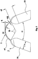
- the bent micro-channel heat exchanger according to an embodiment of the present disclosure comprises a first header 1, a second header. 2, a plurality of flat tubes 3, and a plurality of fins 4.
- the first header 1 and the second header 2 are disposed substantially parallel to each other and spaced apart from each other at a predetermined interval.
- the first header 1 may be used as an inlet header connected with an inlet pipe 110
- the second header 2 may be used as an outlet header connected with an outlet pipe 210.
- each flat tube 3 such as flat tube is connected to the first header 1 and the second header 2 respectively to communicate the first header 1 and the second header 2 via refrigerant channels formed in each flat tube 3.
- each flat tube 3 comprises two straight segments 31 and one bent segment 32, the two straight segments 31 are connected to first and second ends of the bent segment 32, and the bent segment 32 is twisted relative to the two straight segments 31 by a predetermined angle ⁇ .
- each flat tube 3 in order to manufacture the bent micro-channel heat exchanger, a portion (for example, a middle portion which is to be the bent segment) of each flat tube 3 may be twisted relative to the remaining portion of the flat tube 3, and then the flat tube 3 is bent at the portion once such that the flat tube 3 is divided into the two straight segments 31 and one bent segment 32 connected between the two straight segments 31 before assembling and welding of the bent micro-channel heat exchanger.
- the twisted and bent flat tubes 3 are connected to the first header 1 and the second header 2, and each fin 4 is interposed between adjacent flat tubes 3, so that the bent micro-channel heat exchanger is assembled, in which no fins 4 are interposed between adjacent bent segments 32 of the flat tubes 3.
- the flat tubes 3, the first header 1, the second header 2 and the fins 4 are welded together.
- the flat tubes 3 are connected to the first header 1 and the second header 2 before bending and twisting, and each fin 4 is interposed between adjacent flat tubes 3, in which no fins 4 are disposed between portions of flat tubes 3 which are to be bent. Then the flat tubes 3, the first header 1, the second header 2 and the fins 4 are welded together. Finally, the portion of each flat tube 3 is twisted and then each flat tube 3 is bent at the portion without fins such that the portion of each flat tube 3 forms the bent segment of the flat tube 3. It is appreciated that the plurality of flat tubes 3 may be simultaneously twisted and bent.
- the bent micro-channel heat exchanger As shown in Fig. 1 , the bent micro-channel heat exchanger according to the embodiment of the present disclosure is straightened to show a length A of each bent segment 32 before bending and twisted relative to the two straight segments 31. As shown in Fig. 2 , the bent micro-channel heat exchanger is bent and thereby divided into a left bent micro-channel heat exchanger portion and a right bent micro-channel heat exchanger portion located at two sides of the bent segments 32 respectively.
- each fin 4 is interposed between adjacent straight segments 31, but no fins 4 are interposed between adjacent bent segments 32.
- the bent segment 32 may be also called segment without fins, and the straight segment 31 may be also called segment with fins.
- the length A of the bent segment 32 of each flat tube 3 before bending satisfies the following formula: 5 t ⁇ 180 ⁇ ⁇ / 180 + 2 T w ⁇ A ⁇ 30 t ⁇ 180 ⁇ ⁇ / 180 + 8 T w in which A is the length of the bent segment 32 before bending, t is a wall thickness of the flat tube 3 (i.e., a size of the flat tube 3 in an up and down direction in Fig. 1 ), T w is a width of the flat tube 3, ⁇ is an intersection angle between the straight segments 31 of the flat tube 3 after bending the flat tube 3 (i.e., the bending angle of the bent micro-channel heat exchanger), and ⁇ is circumference ratio.
- the flat tube 3 is a flat tube having a substantially oblong cross-section, which is constituted by a middle rectangle and two semicircles connected to two ends of the rectangle. It should be noted that the cross-section of the flat tube 3 is not limited to the above shape, for example, the cross-section of the flat tube 3 may be a flat ellipse or a square.
- the micro-channel heat exchanger is easy to bend and convenient to manufacture simply, the bending radius and the occupying space may be small, the bending angle ⁇ of the micro-channel heat exchanger is not limited, and the water drainage performance is improved.
- the length A of the bent segment 32 before bending satisfies the above formula, the length of the bent segment 32 may reach the permissible minimum value, thus increasing the effective heat exchange area. Therefore, the bent segment 32 may meet the requirements of the bending of the micro-channel heat exchanger, and the bending and the heat exchange performance of the micro-channel heat exchanger may not be affected, that is, the bent segments 32 may be neither too long nor too short. Meanwhile, the micro-channel heat exchanger after bending has orderly appearance. Moreover, the influence of the bending upon the flat tubes 3 is taken into account, so that the service life of the flat tubes 3 and the life of the micro-channel heat exchanger is prolonged.
- the stretching amount S of an upper wall (i.e., the outer surface) of the flat tube 3 has a direct relationship to the wall thickness t of the flat tube 3.
- the larger the stretching amount S the thinner the upper wall of the flat tube 3 is and the lower the bursting strength and the corrosion resistance of the flat tube 3 are. Therefore, the stretching amount S of the upper wall should be controlled.
- the stretching amount S has a direct relationship to the angle ⁇ , the wall thickness t of the flat tube 3 and the bending radius R. If the angle ⁇ is constant, the stretching amount S is in direct proportion to t and in inverse proportion to R . In order to improve the strength and the corrosion resistance of the flat tube 3, it is required that the stretching amount S be as small as possible, and it has been proved by researches that it is advantageous to set R / t ⁇ 5. Meanwhile, if the arc length of the outer surface is kept constant, the larger the bending radius R , the flatter the outer surface is, which is disadvantageous for the water drainage performance of the outer surface, and water may directly drop from the outer surface. It has been proved by researches that it is advantageous to set R / t is ⁇ 30. Therefore, it is advantageous that R is greater than or equal to 5 t and less than or equal to 30 t .
- a 2 is the length of the twisted portion of the bent segment 32, and mainly depends on the twisting force.
- the twisting force is in direct proportion to the width T w of the flat tube 3.
- T w the width of the flat tube 3.
- the smaller the length a 2 of the twisted portion the larger the twisting force is and the more easily the fins 4 deform. Therefore, the larger the length a 2 of the twisted portion, the more difficultly the fins 4 deform. Since the twisted portion does not participate in heat exchange, if the twisted portion is too long, the heat exchange performance of the heat exchanger will be affected disadvantageously. It has been proved by researches that it is advantageous to set T w ⁇ a 2 ⁇ 4 T w .
- the length a 2 of the twisted portion also has a direct relationship to the angle ⁇ by which the bent segment 32 is twisted relative to the two straight segments 31.
- a uniformity of an air stream B on a surface of the heat exchanger has a direct relationship to an angle ⁇ /2 between the air stream B and the heat exchanger (i.e., a half of the intersection angle between the two straight segments 31 of the flat tube 3).
- ⁇ the more uniform the air stream on the surface of the heat exchanger is.
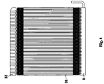
- first ends of the bent segments 32 of the plurality of flat tubes 3 are aligned in an axial direction (i.e., the up and down direction in Fig. 1 or the left and right direction in Fig. 4 ) of the first header 1 and the second header 2, and second ends of the bent segments 32 are also aligned in the axial direction.
- the bent segments 32 overlap partly with each other. Therefore, the micro-channel heat exchanger has orderly appearance, and the deformation of the micro-channel heat exchanger is uniform and easy to control during manufacturing, thus improving the rate of finished products.
Landscapes
- Engineering & Computer Science (AREA)
- Physics & Mathematics (AREA)
- Thermal Sciences (AREA)
- Mechanical Engineering (AREA)
- General Engineering & Computer Science (AREA)
- Geometry (AREA)
- Heat-Exchange Devices With Radiators And Conduit Assemblies (AREA)
Priority Applications (1)
| Application Number | Priority Date | Filing Date | Title |
|---|---|---|---|
| PL11002997T PL2378232T3 (pl) | 2010-04-13 | 2011-04-09 | Zagięty mikrokanałowy wymiennik ciepła |
Applications Claiming Priority (2)
| Application Number | Priority Date | Filing Date | Title |
|---|---|---|---|
| CN201010146939 | 2010-04-13 | ||
| CN2010102134360A CN101846465B (zh) | 2010-04-13 | 2010-06-24 | 换热器 |
Publications (3)
| Publication Number | Publication Date |
|---|---|
| EP2378232A2 EP2378232A2 (en) | 2011-10-19 |
| EP2378232A3 EP2378232A3 (en) | 2017-04-19 |
| EP2378232B1 true EP2378232B1 (en) | 2018-08-08 |
Family
ID=44246591
Family Applications (1)
| Application Number | Title | Priority Date | Filing Date |
|---|---|---|---|
| EP11002997.2A Active EP2378232B1 (en) | 2010-04-13 | 2011-04-09 | Bent micro-channel heat exchanger |
Country Status (7)
| Country | Link |
|---|---|
| US (1) | US9528770B2 (ja) |
| EP (1) | EP2378232B1 (ja) |
| JP (1) | JP2011220674A (ja) |
| CN (1) | CN101846465B (ja) |
| DK (1) | DK2378232T3 (ja) |
| ES (1) | ES2688450T3 (ja) |
| PL (1) | PL2378232T3 (ja) |
Families Citing this family (26)
| Publication number | Priority date | Publication date | Assignee | Title |
|---|---|---|---|---|
| US9437903B2 (en) * | 2012-01-31 | 2016-09-06 | Johnson Controls Technology Company | Method for cooling a lithium-ion battery pack |
| WO2014146505A1 (zh) * | 2013-03-21 | 2014-09-25 | 杭州三花微通道换热器有限公司 | 折弯式换热器及其制造方法 |
| US9851160B2 (en) | 2013-05-03 | 2017-12-26 | Trane International Inc. | Mounting assembly for heat exchanger coil |
| CN104344745A (zh) * | 2013-08-02 | 2015-02-11 | 杭州三花微通道换热器有限公司 | 换热器及其加工方法 |
| US10247482B2 (en) * | 2013-12-13 | 2019-04-02 | Hangzhou Sanhua Research Institute Co., Ltd. | Bent heat exchanger and method for bending the heat exchanger |
| US20150323230A1 (en) * | 2014-03-11 | 2015-11-12 | Brazeway, Inc. | Tube pattern for a refrigerator evaporator |
| EP3221656B1 (en) * | 2014-11-17 | 2020-10-28 | Carrier Corporation | Multi-pass and multi-slab folded microchannel heat exchanger |
| WO2016083457A1 (en) * | 2014-11-25 | 2016-06-02 | Sapa As | Multi port extrusion tubing design |
| CN105783338B (zh) | 2015-01-09 | 2020-11-06 | 特灵国际有限公司 | 热交换器 |
| CN106642826B (zh) * | 2015-10-28 | 2019-04-19 | 丹佛斯微通道换热器(嘉兴)有限公司 | 换热器 |
| USD787033S1 (en) | 2015-12-24 | 2017-05-16 | Danfoss Micro Channel Heat Exchanger (Jiaxing) Co., Ltd. | Heat exchanger |
| CN107560484B (zh) * | 2016-06-30 | 2020-05-19 | 浙江盾安热工科技有限公司 | 连接件和微通道换热器 |
| USD827795S1 (en) * | 2016-07-05 | 2018-09-04 | Danfoss Micro Channel Heat Exchanger (Jiaxing) Co., Ltd. | Heat exchanger |
| USD852338S1 (en) * | 2016-07-05 | 2019-06-25 | Danfoss Micro Channel Heat Exchanger (Jiaxing) Co., Ltd. | Heat exchanger |
| USD839404S1 (en) * | 2016-07-06 | 2019-01-29 | Danfoss Micro Channel Heat Exchanger (Jiaxing) Co., Ltd. | Heat exchanger |
| USD828910S1 (en) * | 2016-07-07 | 2018-09-18 | Danfoss Micro Channel Heat Exchanger (Jiaxing) Co., Ltd. | Heat exchanger |
| CN109640579A (zh) * | 2017-10-09 | 2019-04-16 | 杭州三花家电热管理系统有限公司 | 换热器和设有电子器件的设备 |
| CN108489152A (zh) * | 2018-02-28 | 2018-09-04 | 杭州三花家电热管理系统有限公司 | 换热器、换热设备及换热系统 |
| CN110608552A (zh) * | 2018-06-15 | 2019-12-24 | 杭州三花微通道换热器有限公司 | 换热系统 |
| CN110686429A (zh) * | 2018-07-04 | 2020-01-14 | 浙江盾安热工科技有限公司 | 微通道换热器 |
| CN209445536U (zh) * | 2018-12-21 | 2019-09-27 | 杭州三花微通道换热器有限公司 | 换热装置和具有该换热装置的热泵系统 |
| EP3686525A1 (en) * | 2019-01-25 | 2020-07-29 | Carrier Corporation | Self-venting refrigerant coil |
| US11236946B2 (en) | 2019-05-10 | 2022-02-01 | Carrier Corporation | Microchannel heat exchanger |
| US11890663B2 (en) | 2020-09-23 | 2024-02-06 | Mahle International Gmbh | Device and method for opening folded heat exchanger cores |
| CN215063873U (zh) * | 2021-02-07 | 2021-12-07 | 浙江盾安人工环境股份有限公司 | 换热器及空调设备 |
| WO2024052584A1 (es) * | 2022-09-08 | 2024-03-14 | WGA Water Global Access, SL | Un dispositivo compresor gravitacional de vapor |
Family Cites Families (27)
| Publication number | Priority date | Publication date | Assignee | Title |
|---|---|---|---|---|
| GB658767A (en) * | 1947-09-06 | 1951-10-10 | Ungarische Radiatoren Fabriks | Improvements relating to heat exchange devices for room heating |
| US3265127A (en) * | 1963-10-21 | 1966-08-09 | Ford Motor Co | Heat exchange element |
| US4181173A (en) * | 1978-02-24 | 1980-01-01 | United States Steel Corporation | Heat exchanger assembly |
| US4542786A (en) * | 1981-11-30 | 1985-09-24 | Caterpillar Tractor Co. | Heat exchanger core with varied-angle tubes |
| US4998580A (en) * | 1985-10-02 | 1991-03-12 | Modine Manufacturing Company | Condenser with small hydraulic diameter flow path |
| JPS6312081U (ja) * | 1986-07-11 | 1988-01-26 | ||
| JP3043051B2 (ja) | 1990-11-22 | 2000-05-22 | 昭和アルミニウム株式会社 | 熱交換装置 |
| JP3305460B2 (ja) * | 1993-11-24 | 2002-07-22 | 昭和電工株式会社 | 熱交換器 |
| JP2851540B2 (ja) | 1994-11-17 | 1999-01-27 | 昭和アルミニウム株式会社 | 熱交換器 |
| JP2000193388A (ja) * | 1998-12-22 | 2000-07-14 | Denso Corp | コルゲートフィン及びその製造方法 |
| US6964296B2 (en) * | 2001-02-07 | 2005-11-15 | Modine Manufacturing Company | Heat exchanger |
| US20030102113A1 (en) * | 2001-11-30 | 2003-06-05 | Stephen Memory | Heat exchanger for providing supercritical cooling of a working fluid in a transcritical cooling cycle |
| US7028764B2 (en) * | 2002-03-01 | 2006-04-18 | Ti Group Automotives Systems, Llc | Refrigeration evaporator |
| US20030183378A1 (en) * | 2002-04-02 | 2003-10-02 | Memory Stephen B. | Heat exchanger and folded tube used therein |
| DE10235038A1 (de) * | 2002-07-31 | 2004-02-12 | Behr Gmbh & Co. | Flachrohr-Wärmeübertrager |
| DE10242069B4 (de) * | 2002-09-11 | 2006-04-20 | Webasto Ag | Kälte- beziehungsweise Wärmespeicher und Verfahren zu dessen Herstellung |
| DE10306848A1 (de) * | 2003-02-18 | 2004-08-26 | Behr Gmbh & Co. Kg | Flachrohr mit Umkehrbogenabschnitt und damit aufgebauter Wärmeübertrager |
| EP1844285A4 (en) * | 2005-02-02 | 2011-12-21 | Carrier Corp | MULTI-CHANNEL FLAT TUBE HEAT EXCHANGERS |
| JP2007170718A (ja) | 2005-12-20 | 2007-07-05 | Denso Corp | 熱交換器 |
| US20070169922A1 (en) * | 2006-01-24 | 2007-07-26 | Pautler Donald R | Microchannel, flat tube heat exchanger with bent tube configuration |
| US7921904B2 (en) * | 2007-01-23 | 2011-04-12 | Modine Manufacturing Company | Heat exchanger and method |
| US7900689B2 (en) * | 2007-02-23 | 2011-03-08 | Delphi Technologies, Inc. | Bend relief spacer |
| JP2009216315A (ja) * | 2008-03-11 | 2009-09-24 | Showa Denko Kk | 熱交換器 |
| CN101846475B (zh) * | 2009-03-25 | 2013-12-11 | 三花控股集团有限公司 | 用于热交换器的翅片以及采用该翅片的热交换器 |
| CN101806550B (zh) * | 2010-03-24 | 2014-02-19 | 三花控股集团有限公司 | 微通道换热器 |
| CN201697494U (zh) * | 2010-04-13 | 2011-01-05 | 三花丹佛斯(杭州)微通道换热器有限公司 | 换热器 |
| CN101865625B (zh) * | 2010-06-29 | 2012-09-05 | 三花丹佛斯(杭州)微通道换热器有限公司 | 翅片和具有该翅片的换热器 |
-
2010
- 2010-06-24 CN CN2010102134360A patent/CN101846465B/zh active Active
-
2011
- 2011-04-08 US US13/083,000 patent/US9528770B2/en active Active
- 2011-04-09 ES ES11002997.2T patent/ES2688450T3/es active Active
- 2011-04-09 PL PL11002997T patent/PL2378232T3/pl unknown
- 2011-04-09 DK DK11002997.2T patent/DK2378232T3/en active
- 2011-04-09 EP EP11002997.2A patent/EP2378232B1/en active Active
- 2011-04-12 JP JP2011087818A patent/JP2011220674A/ja active Pending
Non-Patent Citations (1)
| Title |
|---|
| None * |
Also Published As
| Publication number | Publication date |
|---|---|
| CN101846465A (zh) | 2010-09-29 |
| DK2378232T3 (en) | 2018-11-26 |
| US9528770B2 (en) | 2016-12-27 |
| PL2378232T3 (pl) | 2019-01-31 |
| EP2378232A3 (en) | 2017-04-19 |
| US20110247791A1 (en) | 2011-10-13 |
| JP2011220674A (ja) | 2011-11-04 |
| CN101846465B (zh) | 2011-11-09 |
| ES2688450T3 (es) | 2018-11-02 |
| EP2378232A2 (en) | 2011-10-19 |
Similar Documents
| Publication | Publication Date | Title |
|---|---|---|
| EP2378232B1 (en) | Bent micro-channel heat exchanger | |
| EP2369285B1 (en) | Heat exchanger | |
| CN201652995U (zh) | 微通道换热器 | |
| EP3141858B1 (en) | Bended heat exchanger | |
| US9115939B2 (en) | Micro-channel heat exchanger | |
| EP3018439B1 (en) | Fin tube heat exchanger | |
| EP3040667B1 (en) | Heat exchanger | |
| KR20110110722A (ko) | 입구 분배기 및 출구 수집기를 구비한 향상된 열교환기 | |
| JPH07146089A (ja) | 熱交換器 | |
| EP3399269B1 (en) | Double-row bent type heat exchanger and manufacturing method therefor | |
| JP5861549B2 (ja) | チューブ及び該チューブを備えた熱交換器 | |
| US20040251016A1 (en) | Heat exchanger | |
| EP3591324B1 (en) | Micro-channel heat exchanger | |
| EP4290171A1 (en) | Heat exchange tube and heat exchanger having same | |
| CN204043463U (zh) | 翅片和具有该翅片的折弯式换热器 | |
| US20210310742A1 (en) | Heat exchange apparatus and heat pump system provided with same | |
| CN103913088B (zh) | 翅片和具有该翅片的折弯式换热器 | |
| WO2014146505A1 (zh) | 折弯式换热器及其制造方法 | |
| US20230332844A1 (en) | Heat exchanger and processing method therefor | |
| EP3726174B1 (en) | Finless heat exchanger and refrigeration cycle device | |
| CN215810397U (zh) | 微通道换热结构 | |
| WO2019019710A1 (zh) | 换热器和换热装置 | |
| CN210268334U (zh) | 换热器及其换热管 | |
| EP4206598A1 (en) | Heat exchanger and processing method therefor | |
| CN201697494U (zh) | 换热器 |
Legal Events
| Date | Code | Title | Description |
|---|---|---|---|
| AK | Designated contracting states |
Kind code of ref document: A2 Designated state(s): AL AT BE BG CH CY CZ DE DK EE ES FI FR GB GR HR HU IE IS IT LI LT LU LV MC MK MT NL NO PL PT RO RS SE SI SK SM TR |
|
| AX | Request for extension of the european patent |
Extension state: BA ME |
|
| PUAI | Public reference made under article 153(3) epc to a published international application that has entered the european phase |
Free format text: ORIGINAL CODE: 0009012 |
|
| 17P | Request for examination filed |
Effective date: 20120727 |
|
| RAP1 | Party data changed (applicant data changed or rights of an application transferred) |
Owner name: DANFOSS A/S Owner name: SANHUA HOLDING GROUP CO., LTD. |
|
| RAP1 | Party data changed (applicant data changed or rights of an application transferred) |
Owner name: SANHUA (HANGZHOU) MICRO CHANNEL HEAT EXCHANGER CO. Owner name: DANFOSS A/S |
|
| PUAL | Search report despatched |
Free format text: ORIGINAL CODE: 0009013 |
|
| AK | Designated contracting states |
Kind code of ref document: A3 Designated state(s): AL AT BE BG CH CY CZ DE DK EE ES FI FR GB GR HR HU IE IS IT LI LT LU LV MC MK MT NL NO PL PT RO RS SE SI SK SM TR |
|
| AX | Request for extension of the european patent |
Extension state: BA ME |
|
| RIC1 | Information provided on ipc code assigned before grant |
Ipc: F28F 1/32 20060101ALI20170315BHEP Ipc: F28D 1/047 20060101AFI20170315BHEP Ipc: F28D 1/053 20060101ALI20170315BHEP |
|
| TPAC | Observations filed by third parties |
Free format text: ORIGINAL CODE: EPIDOSNTIPA |
|
| GRAP | Despatch of communication of intention to grant a patent |
Free format text: ORIGINAL CODE: EPIDOSNIGR1 |
|
| STAA | Information on the status of an ep patent application or granted ep patent |
Free format text: STATUS: GRANT OF PATENT IS INTENDED |
|
| INTG | Intention to grant announced |
Effective date: 20180411 |
|
| GRAS | Grant fee paid |
Free format text: ORIGINAL CODE: EPIDOSNIGR3 |
|
| GRAA | (expected) grant |
Free format text: ORIGINAL CODE: 0009210 |
|
| STAA | Information on the status of an ep patent application or granted ep patent |
Free format text: STATUS: THE PATENT HAS BEEN GRANTED |
|
| AK | Designated contracting states |
Kind code of ref document: B1 Designated state(s): AL AT BE BG CH CY CZ DE DK EE ES FI FR GB GR HR HU IE IS IT LI LT LU LV MC MK MT NL NO PL PT RO RS SE SI SK SM TR |
|
| REG | Reference to a national code |
Ref country code: GB Ref legal event code: FG4D |
|
| REG | Reference to a national code |
Ref country code: CH Ref legal event code: EP Ref country code: AT Ref legal event code: REF Ref document number: 1027489 Country of ref document: AT Kind code of ref document: T Effective date: 20180815 |
|
| REG | Reference to a national code |
Ref country code: IE Ref legal event code: FG4D |
|
| REG | Reference to a national code |
Ref country code: DE Ref legal event code: R096 Ref document number: 602011050725 Country of ref document: DE |
|
| REG | Reference to a national code |
Ref country code: ES Ref legal event code: FG2A Ref document number: 2688450 Country of ref document: ES Kind code of ref document: T3 Effective date: 20181102 |
|
| REG | Reference to a national code |
Ref country code: DK Ref legal event code: T3 Effective date: 20181119 |
|
| REG | Reference to a national code |
Ref country code: NL Ref legal event code: MP Effective date: 20180808 |
|
| REG | Reference to a national code |
Ref country code: LT Ref legal event code: MG4D |
|
| REG | Reference to a national code |
Ref country code: AT Ref legal event code: MK05 Ref document number: 1027489 Country of ref document: AT Kind code of ref document: T Effective date: 20180808 |
|
| PG25 | Lapsed in a contracting state [announced via postgrant information from national office to epo] |
Ref country code: LT Free format text: LAPSE BECAUSE OF FAILURE TO SUBMIT A TRANSLATION OF THE DESCRIPTION OR TO PAY THE FEE WITHIN THE PRESCRIBED TIME-LIMIT Effective date: 20180808 Ref country code: AT Free format text: LAPSE BECAUSE OF FAILURE TO SUBMIT A TRANSLATION OF THE DESCRIPTION OR TO PAY THE FEE WITHIN THE PRESCRIBED TIME-LIMIT Effective date: 20180808 Ref country code: NL Free format text: LAPSE BECAUSE OF FAILURE TO SUBMIT A TRANSLATION OF THE DESCRIPTION OR TO PAY THE FEE WITHIN THE PRESCRIBED TIME-LIMIT Effective date: 20180808 Ref country code: BG Free format text: LAPSE BECAUSE OF FAILURE TO SUBMIT A TRANSLATION OF THE DESCRIPTION OR TO PAY THE FEE WITHIN THE PRESCRIBED TIME-LIMIT Effective date: 20181108 Ref country code: NO Free format text: LAPSE BECAUSE OF FAILURE TO SUBMIT A TRANSLATION OF THE DESCRIPTION OR TO PAY THE FEE WITHIN THE PRESCRIBED TIME-LIMIT Effective date: 20181108 Ref country code: SE Free format text: LAPSE BECAUSE OF FAILURE TO SUBMIT A TRANSLATION OF THE DESCRIPTION OR TO PAY THE FEE WITHIN THE PRESCRIBED TIME-LIMIT Effective date: 20180808 Ref country code: IS Free format text: LAPSE BECAUSE OF FAILURE TO SUBMIT A TRANSLATION OF THE DESCRIPTION OR TO PAY THE FEE WITHIN THE PRESCRIBED TIME-LIMIT Effective date: 20181208 Ref country code: RS Free format text: LAPSE BECAUSE OF FAILURE TO SUBMIT A TRANSLATION OF THE DESCRIPTION OR TO PAY THE FEE WITHIN THE PRESCRIBED TIME-LIMIT Effective date: 20180808 Ref country code: GR Free format text: LAPSE BECAUSE OF FAILURE TO SUBMIT A TRANSLATION OF THE DESCRIPTION OR TO PAY THE FEE WITHIN THE PRESCRIBED TIME-LIMIT Effective date: 20181109 Ref country code: FI Free format text: LAPSE BECAUSE OF FAILURE TO SUBMIT A TRANSLATION OF THE DESCRIPTION OR TO PAY THE FEE WITHIN THE PRESCRIBED TIME-LIMIT Effective date: 20180808 |
|
| PG25 | Lapsed in a contracting state [announced via postgrant information from national office to epo] |
Ref country code: LV Free format text: LAPSE BECAUSE OF FAILURE TO SUBMIT A TRANSLATION OF THE DESCRIPTION OR TO PAY THE FEE WITHIN THE PRESCRIBED TIME-LIMIT Effective date: 20180808 Ref country code: AL Free format text: LAPSE BECAUSE OF FAILURE TO SUBMIT A TRANSLATION OF THE DESCRIPTION OR TO PAY THE FEE WITHIN THE PRESCRIBED TIME-LIMIT Effective date: 20180808 Ref country code: HR Free format text: LAPSE BECAUSE OF FAILURE TO SUBMIT A TRANSLATION OF THE DESCRIPTION OR TO PAY THE FEE WITHIN THE PRESCRIBED TIME-LIMIT Effective date: 20180808 |
|
| PG25 | Lapsed in a contracting state [announced via postgrant information from national office to epo] |
Ref country code: EE Free format text: LAPSE BECAUSE OF FAILURE TO SUBMIT A TRANSLATION OF THE DESCRIPTION OR TO PAY THE FEE WITHIN THE PRESCRIBED TIME-LIMIT Effective date: 20180808 Ref country code: RO Free format text: LAPSE BECAUSE OF FAILURE TO SUBMIT A TRANSLATION OF THE DESCRIPTION OR TO PAY THE FEE WITHIN THE PRESCRIBED TIME-LIMIT Effective date: 20180808 Ref country code: CZ Free format text: LAPSE BECAUSE OF FAILURE TO SUBMIT A TRANSLATION OF THE DESCRIPTION OR TO PAY THE FEE WITHIN THE PRESCRIBED TIME-LIMIT Effective date: 20180808 |
|
| REG | Reference to a national code |
Ref country code: DE Ref legal event code: R097 Ref document number: 602011050725 Country of ref document: DE |
|
| PG25 | Lapsed in a contracting state [announced via postgrant information from national office to epo] |
Ref country code: SM Free format text: LAPSE BECAUSE OF FAILURE TO SUBMIT A TRANSLATION OF THE DESCRIPTION OR TO PAY THE FEE WITHIN THE PRESCRIBED TIME-LIMIT Effective date: 20180808 Ref country code: SK Free format text: LAPSE BECAUSE OF FAILURE TO SUBMIT A TRANSLATION OF THE DESCRIPTION OR TO PAY THE FEE WITHIN THE PRESCRIBED TIME-LIMIT Effective date: 20180808 |
|
| PLBE | No opposition filed within time limit |
Free format text: ORIGINAL CODE: 0009261 |
|
| STAA | Information on the status of an ep patent application or granted ep patent |
Free format text: STATUS: NO OPPOSITION FILED WITHIN TIME LIMIT |
|
| 26N | No opposition filed |
Effective date: 20190509 |
|
| PG25 | Lapsed in a contracting state [announced via postgrant information from national office to epo] |
Ref country code: SI Free format text: LAPSE BECAUSE OF FAILURE TO SUBMIT A TRANSLATION OF THE DESCRIPTION OR TO PAY THE FEE WITHIN THE PRESCRIBED TIME-LIMIT Effective date: 20180808 |
|
| REG | Reference to a national code |
Ref country code: CH Ref legal event code: PL |
|
| REG | Reference to a national code |
Ref country code: BE Ref legal event code: MM Effective date: 20190430 |
|
| GBPC | Gb: european patent ceased through non-payment of renewal fee |
Effective date: 20190409 |
|
| PG25 | Lapsed in a contracting state [announced via postgrant information from national office to epo] |
Ref country code: LU Free format text: LAPSE BECAUSE OF NON-PAYMENT OF DUE FEES Effective date: 20190409 Ref country code: MC Free format text: LAPSE BECAUSE OF FAILURE TO SUBMIT A TRANSLATION OF THE DESCRIPTION OR TO PAY THE FEE WITHIN THE PRESCRIBED TIME-LIMIT Effective date: 20180808 |
|
| PG25 | Lapsed in a contracting state [announced via postgrant information from national office to epo] |
Ref country code: CH Free format text: LAPSE BECAUSE OF NON-PAYMENT OF DUE FEES Effective date: 20190430 Ref country code: LI Free format text: LAPSE BECAUSE OF NON-PAYMENT OF DUE FEES Effective date: 20190430 Ref country code: GB Free format text: LAPSE BECAUSE OF NON-PAYMENT OF DUE FEES Effective date: 20190409 |
|
| PG25 | Lapsed in a contracting state [announced via postgrant information from national office to epo] |
Ref country code: BE Free format text: LAPSE BECAUSE OF NON-PAYMENT OF DUE FEES Effective date: 20190430 |
|
| PG25 | Lapsed in a contracting state [announced via postgrant information from national office to epo] |
Ref country code: TR Free format text: LAPSE BECAUSE OF FAILURE TO SUBMIT A TRANSLATION OF THE DESCRIPTION OR TO PAY THE FEE WITHIN THE PRESCRIBED TIME-LIMIT Effective date: 20180808 |
|
| PG25 | Lapsed in a contracting state [announced via postgrant information from national office to epo] |
Ref country code: IE Free format text: LAPSE BECAUSE OF NON-PAYMENT OF DUE FEES Effective date: 20190409 |
|
| PG25 | Lapsed in a contracting state [announced via postgrant information from national office to epo] |
Ref country code: PT Free format text: LAPSE BECAUSE OF FAILURE TO SUBMIT A TRANSLATION OF THE DESCRIPTION OR TO PAY THE FEE WITHIN THE PRESCRIBED TIME-LIMIT Effective date: 20181208 |
|
| PG25 | Lapsed in a contracting state [announced via postgrant information from national office to epo] |
Ref country code: CY Free format text: LAPSE BECAUSE OF FAILURE TO SUBMIT A TRANSLATION OF THE DESCRIPTION OR TO PAY THE FEE WITHIN THE PRESCRIBED TIME-LIMIT Effective date: 20180808 |
|
| PG25 | Lapsed in a contracting state [announced via postgrant information from national office to epo] |
Ref country code: HU Free format text: LAPSE BECAUSE OF FAILURE TO SUBMIT A TRANSLATION OF THE DESCRIPTION OR TO PAY THE FEE WITHIN THE PRESCRIBED TIME-LIMIT; INVALID AB INITIO Effective date: 20110409 Ref country code: MT Free format text: LAPSE BECAUSE OF FAILURE TO SUBMIT A TRANSLATION OF THE DESCRIPTION OR TO PAY THE FEE WITHIN THE PRESCRIBED TIME-LIMIT Effective date: 20180808 |
|
| PG25 | Lapsed in a contracting state [announced via postgrant information from national office to epo] |
Ref country code: MK Free format text: LAPSE BECAUSE OF FAILURE TO SUBMIT A TRANSLATION OF THE DESCRIPTION OR TO PAY THE FEE WITHIN THE PRESCRIBED TIME-LIMIT Effective date: 20180808 |
|
| P01 | Opt-out of the competence of the unified patent court (upc) registered |
Effective date: 20230529 |
|
| PGFP | Annual fee paid to national office [announced via postgrant information from national office to epo] |
Ref country code: IT Payment date: 20230428 Year of fee payment: 13 Ref country code: FR Payment date: 20230417 Year of fee payment: 13 Ref country code: ES Payment date: 20230517 Year of fee payment: 13 Ref country code: DK Payment date: 20230419 Year of fee payment: 13 Ref country code: DE Payment date: 20230425 Year of fee payment: 13 |
|
| PGFP | Annual fee paid to national office [announced via postgrant information from national office to epo] |
Ref country code: PL Payment date: 20230504 Year of fee payment: 13 |