EP2377218B1 - Überspannungsschutzelement - Google Patents
Überspannungsschutzelement Download PDFInfo
- Publication number
- EP2377218B1 EP2377218B1 EP10701449.0A EP10701449A EP2377218B1 EP 2377218 B1 EP2377218 B1 EP 2377218B1 EP 10701449 A EP10701449 A EP 10701449A EP 2377218 B1 EP2377218 B1 EP 2377218B1
- Authority
- EP
- European Patent Office
- Prior art keywords
- overvoltage
- resistor
- gas
- surge arrester
- overvoltage protection
- Prior art date
- Legal status (The legal status is an assumption and is not a legal conclusion. Google has not performed a legal analysis and makes no representation as to the accuracy of the status listed.)
- Not-in-force
Links
Images


Classifications
-
- H—ELECTRICITY
- H02—GENERATION; CONVERSION OR DISTRIBUTION OF ELECTRIC POWER
- H02H—EMERGENCY PROTECTIVE CIRCUIT ARRANGEMENTS
- H02H9/00—Emergency protective circuit arrangements for limiting excess current or voltage without disconnection
- H02H9/04—Emergency protective circuit arrangements for limiting excess current or voltage without disconnection responsive to excess voltage
-
- H—ELECTRICITY
- H02—GENERATION; CONVERSION OR DISTRIBUTION OF ELECTRIC POWER
- H02H—EMERGENCY PROTECTIVE CIRCUIT ARRANGEMENTS
- H02H9/00—Emergency protective circuit arrangements for limiting excess current or voltage without disconnection
- H02H9/04—Emergency protective circuit arrangements for limiting excess current or voltage without disconnection responsive to excess voltage
- H02H9/042—Emergency protective circuit arrangements for limiting excess current or voltage without disconnection responsive to excess voltage comprising means to limit the absorbed power or indicate damaged over-voltage protection device
-
- H—ELECTRICITY
- H02—GENERATION; CONVERSION OR DISTRIBUTION OF ELECTRIC POWER
- H02H—EMERGENCY PROTECTIVE CIRCUIT ARRANGEMENTS
- H02H1/00—Details of emergency protective circuit arrangements
- H02H1/0061—Details of emergency protective circuit arrangements concerning transmission of signals
- H02H1/0069—Details of emergency protective circuit arrangements concerning transmission of signals by means of light or heat rays
-
- H—ELECTRICITY
- H02—GENERATION; CONVERSION OR DISTRIBUTION OF ELECTRIC POWER
- H02H—EMERGENCY PROTECTIVE CIRCUIT ARRANGEMENTS
- H02H3/00—Emergency protective circuit arrangements for automatic disconnection directly responsive to an undesired change from normal electric working condition with or without subsequent reconnection ; integrated protection
- H02H3/02—Details
- H02H3/04—Details with warning or supervision in addition to disconnection, e.g. for indicating that protective apparatus has functioned
- H02H3/044—Checking correct functioning of protective arrangements, e.g. by simulating a fault
Definitions
- the invention relates to an overvoltage protection element with a housing and with at least one arranged in the housing overvoltage limiting component, in particular a gas-filled surge arrester, a spark gap, a suppressor diode or a varistor, wherein the overvoltage limiting component is assigned a monitoring component, and wherein the signal of Monitoring unit evaluating evaluating unit is provided, which is galvanically separated from the Ableitstrompfad over which the current detected by the monitoring device current.
- overvoltage protection can be divided into different fields of application.
- overvoltage protection for the power supply, for measurement and control technology (MSR technology) and for information technology and telecommunications.
- Interfaces of the MCR technology are far more sensitive to overvoltages than power supply systems.
- overvoltage protection elements with combined protective circuits are therefore generally used in the field of MCR, with at least one overvoltage limiting component serving for coarse protection and at least one overvoltage limiting component for fine protection.
- an indirect parallel connection of a gas-filled surge arrester and a suppressor diode is used, wherein a decoupling resistor is arranged between the gas-filled surge arrester and the suppressor diode.
- the known overvoltage protection elements are often designed as "protective plug", which together with a device lower part form an overvoltage protection device.
- a surge protection device corresponding terminals for the individual conductors are provided on the bottom of the device.
- the connection elements are designed as plug pins in the overvoltage protection element, corresponding to those in the device lower part, with the Terminals connected sockets are arranged so that the overvoltage protection element is simply plugged onto the device base.
- overvoltage protection devices In such overvoltage protection devices, the installation and assembly by plugging the overvoltage protection element is very simple and time-saving feasible.
- overvoltage protection devices partly still have a remote indication, as a signal generator of the state of the overvoltage protection element, which is usually designed as a changeover contact, as well as an optical status display in the overvoltage protection element.
- the status display indicates whether the overvoltage-limiting component arranged in the overvoltage protection element is still functional or not.
- varistors, gas-filled surge arresters, spark gaps or diodes, in particular suppressor diodes are used as the overvoltage limiting component.
- overvoltage protection elements with a varistor as a drain therefore, nowadays often have a thermal separation device, by means of which a varistor which is no longer functioning properly is electrically disconnected from the current path to be monitored.
- thermal cut-off devices are also used in the case of overvoltage protection elements with spark gaps as arresters.
- Such an overvoltage protection element is for example from the DE 20 2004 006 227 U1 known.
- the monitoring of the state of a overvoltage limiting component, in particular a varistor according to the principle of a temperature switch, so that when overheating of the varistor a provided between the varistor and a separator solder joint is separated, resulting in electrical separation of the varistor.
- a plastic element is pushed by the restoring force of a spring from a first position to a second position, in which the separating element formed as a resilient metal tongue is thermally and electrically separated from the varistor by the plastic element.
- the plastic element Since the plastic element has two juxtaposed colored markings, it also acts as an optical status indicator, whereby the state of the overvoltage protection element can be easily read directly on site. By such an integrated display, however, only a defect of the overvoltage protection element can be signaled.
- overvoltage protection devices are exposed to high surge current loads, the individual overvoltage limiting components can be damaged depending on the magnitude and frequency of the stresses, so that the functionality of the surge voltage elements should be checked regularly.
- the Applicant markets a portable arrester test device under the name "CHECKMASTER” (US Pat. Catalog TRABTECH 2007, pages 166 to 173 ), which has a test receptacle into which the respective protective plug to be tested can be inserted.
- the current electrical parameters of the overvoltage limiting components are determined and compared with reference values, wherein by a tolerance value measurement heavily loaded components are identified as pre-damaged.
- the Ableiterprüfcuit thus allows - in addition to displaying a faulty overvoltage protection element - also a check-up of an overvoltage protection element.
- the disadvantage is that for this purpose the overvoltage protection element must be removed from the lower device part, so that a test during operation is not possible.
- the present invention has for its object to provide an initially described overvoltage protection element that allows easy control of the functionality and the state of the overvoltage protection element during operation.
- a optocoupler is used as a monitoring device, which is connected in parallel with a arranged in series with the overvoltage limiting component resistor and detects the current flowing through the resistor current.
- the use of an opto-coupler as a monitoring device is suitable both for overvoltage limiting components that serve the coarse protection, for example in a gas-filled surge arrester or a spark gap, as well as overvoltage limiting components that serve the fine protection, such as a suppressor diode.
- a monitoring component is assigned to the overvoltage limiting component which detects a current flowing through the overvoltage limiting component, in particular a leakage current
- a detection of the load of the overvoltage limiting component during operation is possible.
- a corresponding evaluation unit which evaluates the signal supplied by the monitoring component due to a current flowing across the overvoltage limiting component, a statement about the loading of a component limiting the overvoltage is possible, before a defect of the component occurs.
- the evaluation unit is preferably designed so that it also evaluates the duration of the load, ie the duration of the leakage current, in addition to the frequency and the magnitude of the load on a surge-limiting component.
- the galvanic separation of the evaluation unit from the leakage current path protects the evaluation unit from damage and enables a reduction in the amplitude of the signal to be evaluated by the evaluation unit ,
- the resistor connected in series with the overvoltage limiting component which has the optocoupler connected in parallel, has the function of a shunt.
- the resistor thus has a relatively low value, so that it does not affect the function of the overvoltage limiting component.
- the overvoltage protection element has both a gas-filled surge arrester or a spark gap and a suppressor diode as overvoltage limiting components and in which a decoupling resistor is arranged between the gas-filled surge arrester or the spark gap and the suppressor diode the optocoupler is connected in parallel to the decoupling resistor.
- An overvoltage protection element with a gas-filled surge arrester, a suppressor diode and a decoupling resistor is known from the prior art, in particular in the field of MCR.
- the optocoupler as a monitoring component is simply connected in parallel with the decoupling resistor which is present anyway.
- the current through the decoupling resistor corresponds to the current through the suppressor diode, so that the load of the suppressor diode can be determined by detecting the current through the decoupling resistor with the aid of the opto-coupler and from this a statement can be made about its anticipated service life , In addition, exceeding the permissible load current flowing through the decoupling resistor can be detected, so that damage to the resistor can be displayed or prevented.
- the optocoupler Regardless of whether a gas-filled surge arrester or a suppressor diode is monitored for their function by means of the optocoupler, the optocoupler produces the galvanic isolation to the evaluation unit and translates a measured current through the leakage current path into a smaller, easily measurable and evaluable current. It is of course also possible that in an overvoltage element with a gas-filled surge arrester or a spark gap and with a suppressor diode, the functionality of the gas-filled surge arrester is monitored by an optocoupler and the functionality of the suppressor diode of another optocoupler.
- At least one optical status display for the at least one overvoltage limiting component is arranged in the housing, so that the state of the overvoltage protection element or of a overvoltage limiting component can be displayed directly on site.
- the status display can preferably have three areas with different markings, in particular three areas with different colors, for example green, yellow and red, so that not only the defect of a surge-limiting component but also a previous damage can be displayed. If the overvoltage protection element has a plurality of overvoltage-limiting components, its state can be separately indicated for each component.
- the overvoltage protection element in addition to the optical status display on a remote signaling contact for remote indication of the state of the overvoltage protection element or the states of the individual overvoltage limiting components.
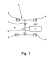
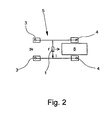
- FIG. 1 to 3 each show an embodiment in which a gas-filled surge arrester 1 is provided as overvoltage limiting component.
- a gas-filled surge arrester 1 In the embodiment according to the Fig. 4
- a suppressor diode 2 In addition to a gas-filled surge arrester 1 as coarse protection nor a suppressor diode 2 is provided as fine protection.
- the simplified circuits shown in the figures each have two input terminals 3 for connecting two lines and two output terminals 4 for connecting the device to be protected, for example, a sensor or a controller on. Other connections, in particular a ground connection can be provided, even if they are not shown in the figures.
- the exemplary embodiments have in common that the gas-filled surge arrester 1 ( Fig. 1 to 3 ) or the suppressor diode 2 ( Fig. 4 ) is assigned a monitoring component, which detects a flowing over the gas-filled surge arrester 1 and the suppressor diode 2 current i.
- the signal generated as a function of the current i from the monitoring component is evaluated in an evaluation unit-not shown here-wherein the evaluation unit in the exemplary embodiments according to FIGS Fig. 1 to 4 galvanic of the Ableitstrompfad 5, via which the current i through the gas-filled surge arrester 1 or the suppressor diode 2 flows, is separated.
- the monitoring device is a coil 6, which is inductively coupled to the Ableitstrompfad 5, so that from the coil 6, a current i is detected by the gas-filled surge arrester 1.
- the coil 6 is connected to an integrator 7, whereby the energy of the current pulse can be determined by the gas-filled surge arrester 1. From the pulse energy, the load of the gas-filled surge arrester 1 can be determined by the leakage current i.
- a photo element 8 is used as a monitoring device, wherein the photo element 8 is arranged adjacent to the gas-filled surge arrester 1, that is detected by the photo element 8 a pending in the presence of an overvoltage in the gas-filled surge arrester 1 arc.
- suitable signal processing it is possible to determine the intensity and the duration of the discharge process and thus a measure of the load of the gas-filled surge arrester 1 on the basis of the arc detected by the photoelement 8.
- an optocoupler 9 wherein the optocoupler 9 in the variant according to Fig. 3 is arranged parallel to a resistor 10 in series with the gas-filled surge arrester 1. While in the embodiment according to Fig. 3 the functionality of the gas-filled surge arrester 1 is monitored with the optocoupler 9, the optocoupler 9 is used in the embodiment according to Fig. 4 For this purpose, the optocoupler 9 is connected in parallel with a decoupling resistor 11 which is arranged between the gas-filled surge arrester 1 and the suppressor diode 2.
- a further resistor 12 is arranged, whose resistance value is substantially greater than the resistance of the resistor 10 and the decoupling resistor 11.
- the decoupling resistor 11 is in the range of a few ohms while the resistor 12 is for example in the range of a few hundred ohms.
- the optocoupler 9 serves to detect the current flowing through the resistor 10 and the decoupling resistor 11, wherein the optocoupler 9 and a downstream evaluation both the amplitude and the duration of a through the resistor 10 and the decoupling resistor 11 and Thus, in the case of high-resistance termination, the current pulse i flowing through the gas-filled surge arrester 1 or the suppressor diode 2 is also detected.
- an overvoltage protection element which has both a gas-filled surge arrester 1 and a suppressor diode 2
- the functionality of the gas-filled surge arrester 1 by means of a first opto-coupler 9 and the functionality of the suppressor diode 2 are monitored by means of a second optocoupler 9.
- the functionality of the gas-filled surge arrester 1 with a coil 6 according to Fig. 1 or with a photoelement 8 according to Fig. 2 to monitor.
Landscapes
- Physics & Mathematics (AREA)
- Electromagnetism (AREA)
- Emergency Protection Circuit Devices (AREA)
Description
- Die Erfindung betrifft ein Überspannungsschutzelement mit einem Gehäuse und mit mindestens einem in dem Gehäuse angeordneten überspannungsbegrenzenden Bauelement, insbesondere einem gasgefüllten Überspannungsableiter, einer Funkenstrecke, einer Suppressor-Diode oder einem Varistor, wobei dem überspannungsbegrenzenden Bauelement ein Überwachungsbauelement zugeordnet ist, und wobei eine das Signal des Überwachungsbauelements auswertende Auswerteeinheit vorgesehen ist, die galvanisch von dem Ableitstrompfad, über den der von dem Überwachungsbauelement erfasste Strom fließt, getrennt ist.
- Der Überspannungsschutz kann in unterschiedliche Einsatzgebiete aufgeteilt werden. Dabei unterscheidet man insbesondere zwischen Überspannungsschutz für die Stromversorgung, für die Mess-, Steuer- und Regeltechnik (MSR-Technik) und für die Informationstechnik und Telekommunikation. Schnittstellen der MSR-Technik sind gegen Überspannungen weitaus empfindlicher als Stromversorgungssysteme. Für den Überspannungsschutz werden daher im MSR-Bereich zumeist Überspannungsschutzelemente mit kombinierten Schutzschaltungen verwendet, wobei mindestens ein überspannungsbegrenzendes Bauelement dem Grobschutz und mindestens ein überspannungsbegrenzendes Bauelement dem Feinschutz dient. Häufig wird dabei eine indirekte Parallelschaltung eines gasgefülltem Überspannungsableiter und einer Suppressor-Diode verwendet, wobei zwischen dem gasgefüllten Überspannungsableiter und der Suppressor-Diode ein Entkopplungswiderstand angeordnet ist.
- Die bekannten Überspannungsschutzelemente sind häufig als "Schutzstecker" ausgebildet, die zusammen mit einem Geräteunterteil ein Überspannungsschutzgerät bilden. Zur Installation eines derartigen Überspannungsschutzgeräts sind am Geräteunterteil entsprechende Anschlussklemmen für die einzelnen Leiter vorgesehen. Zur einfachen mechanischen und elektrischen Kontaktierung des Geräteunterteils mit dem jeweiligen Überspannungsschutzelement sind bei dem Überspannungsschutzelement die Anschlusselemente als Steckerstifte ausgebildet, zu denen im Geräteunterteil korrespondierende, mit den Anschlussklemmen verbundene Steckerbuchsen angeordnet sind, so dass das Überspannungsschutzelement einfach auf das Geräteunterteil aufsteckbar ist.
- Bei derartigen Überspannungsschutzgeräten ist die Installation und Montage durch die Steckbarkeit des Überspannungsschutzelements sehr einfach und zeitsparend durchführbar. Zusätzlich weisen derartige Überspannungsschutzgeräte teilweise noch eine Fernmeldung, als Signalgeber des Zustands des Überspannungsschutzelements, die üblicherweise als Wechselkontakt ausgeführt ist, sowie eine optische Zustandsanzeige im Überspannungsschutzelement auf. Über die Zustandsanzeige wird angezeigt, ob das in dem Überspannungsschutzelement angeordnete überspannungsbegrenzende Bauelement noch funktionstüchtig ist oder nicht. Als überspannungsbegrenzendes Bauelement werden je nach Einsatzzweck des Überspannungsschutzelements Varistoren, gasgefüllten Überspannungsableiter, Funkenstrecken oder Dioden, insbesondere Suppressor-Dioden eingesetzt.
- Aufgrund von Alterung, Vorschädigung durch Ableitvorgänge und zeitweise auftretenden Überspannungen (TOV) im Sekundenbereich kommt es insbesondere bei Überspannungsschutzelementen mit einem Varistor als überspannungsbegrenzendes Bauelement zu einer unerwünschten Erhöhung des Leckstromes des Varistors bei Betriebsspannungen. Überspannungsschutzelemente mit einem Varistor als Ableiter weisen daher heutzutage häufig eine thermische Abtrennvorrichtung auf, durch die ein nicht mehr einwandfrei funktionsfähiger Varistor elektrisch von dem zu überwachenden Strompfad abgetrennt wird. Darüber hinaus werden thermische Abtrennvorrichtungen auch bei Überspannungsschutzelementen mit Funkenstrecken als Ableiter verwendet.
- Eine derartiges Überspannungsschutzelement ist beispielsweise aus der
DE 20 2004 006 227 U1 bekannt. Bei dem bekannten Überspannungsschutzelement erfolgt die Überwachung des Zustands eines überspannungsbegrenzenden Bauelements, insbesondere eines Varistors, nach dem Prinzip eines Temperaturschalters, so dass bei Überhitzung des Varistors eine zwischen dem Varistor und einem Trennelement vorgesehene Lötverbindung aufgetrennt wird, was zu einem elektrischen Abtrennen des Varistors führt. Außerdem wird beim Auftrennen der Lötverbindung ein Kunststoffelement durch die Rückstellkraft einer Feder aus einer ersten Position in eine zweite Position geschoben, in der das als federnde Metallzunge ausgebildete Trennelement durch das Kunststoffelement thermisch und elektrisch vom Varistor getrennt ist. Da das Kunststoffelement zwei nebeneinander angeordnete farbige Markierungen aufweist, fungiert es zusätzlich auch als optische Zustandsanzeige, wodurch der Zustand des Überspannungsschutzelements direkt vor Ort einfach abgelesen werden kann. Durch eine derartige integrierte Anzeige kann jedoch nur ein Defekt des Überspannungsschutzelements signalisiert werden. - Da Überspannungsschutzgeräte hohen Stossstrombelastungen ausgesetzt sind, können die einzelnen überspannungsbegrenzenden Bauelemente in Abhängigkeit von der Höhe und Häufigkeit der Beanspruchungen Schaden nehmen, so dass die Funktionstüchtigkeit der Überspannungselemente regelmäßig kontrolliert werden sollte. Zur Kontrolle der Funktionstüchtigkeit steckbarer Überspannungsschutzelemente wird von der Anmelderin ein tragbares Ableiterprüfgerät unter dem Namen "CHECKMASTER" vertrieben (Katalog TRABTECH 2007, Seite 166 bis 173), das eine Prüfaufnahme aufweist, in die der jeweils zu prüfende Schutzstecker eingesteckt werden kann. Dabei werden die aktuellen elektrischen Parameter der überspannungsbegrenzenden Bauelemente ermittelt und mit Referenzwerten verglichen, wobei durch eine Toleranzwertmessung stark belastete Bauelemente als vorgeschädigt identifiziert werden. Das Ableiterprüfgerät ermöglicht somit - zusätzlich zur Anzeige einest defekten Überspannungsschutzelements - auch eine Vorsorgeuntersuchung eines Überspannungsschutzelements. Nachteilig ist jedoch, dass hierzu das Überspannungsschutzelement von dem Geräteunterteil abgenommen werden muss, so dass ein Test während des Betriebs nicht möglich ist.
- Aus der
US 6,600,425 B1 ist ein eingangs beschriebenes Überspannungsschutzelement mit einem gasgefüllten Überspannungsableiter bekannt, bei dem ein lichtempfindlicher Sensor derart optisch mit dem Überspannungsableiter verbunden und zusammen mit diesem in einem lichtundurchlässigem Gehäuse angeordnet ist, dass der Sensor einen anstehenden Lichtbogen erfasst. Beim Anstehen eines Lichtbogens im dem gasgefüllten Überspannungsableiter erzeugt daher der Sensor ein Signal, dass von einer Auswerteeinheit auswertet wird, die mit dem Sensor verbunden ist. Da die Helligkeit und die Dauer des Lichtbogens von der anstehenden Überspannung abhängt, soll anhand des Signals des Sensors eine Aussage über die Größe und Dauer der anstehenden Überspannung gewonnen werden. Eine genaue Aussage über die Größe und Dauer der anstehenden Überspannung ist jedoch nur mit relativ großem Aufwand und unter Berücksichtigung von mehreren Referenzmessungen möglich. - Der vorliegenden Erfindung liegt die Aufgabe zugrunde, ein eingangs beschriebenes Überspannungsschutzelement zur Verfügung zu stellen, das eine einfache Kontrolle der Funktionstüchtigkeit und des Zustandes des Überspannungsschutzelements während des Betriebs ermöglicht.
- Diese Aufgabe ist bei dem eingangs beschriebenen Überspannungsschutzelement dadurch gelöst, dass als Überwachungsbauelement ein Optokoppler verwendet wird, der parallel zu einem in Reihe mit dem überspannungsbegrenzenden Bauelement angeordneten Widerstand geschaltet ist und den durch den Widerstand fließenden Strom erfasst. Die Verwendung eines Optokopplers als Überwachungsbauelement eignet sich sowohl bei überspannungsbegrenzenden Bauelementen, die dem Grobschutz dienen, beispielsweise bei einem gasgefüllten Überspannungsableiter oder einer Funkenstrecke, als auch bei überspannungsbegrenzenden Bauelementen, die dem Feinschutz dienen, beispielsweise einer Suppressor-Diode.
- Dadurch, dass dem überspannungsbegrenzenden Bauelement ein Überwachungsbauelement zugeordnet ist, das einen über das überspannungsbegrenzende Bauelement fließenden Strom, insbesondere einen Ableitstrom, erfasst, ist eine Erfassung der Beanspruchung des überspannungsbegrenzenden Bauelements im Betrieb möglich. Durch die Verwendung einer entsprechenden Auswerteeinheit, die das von dem Überwachungsbauelement aufgrund eines über das überspannungsbegrenzende Bauelement fließenden Stromes gelieferte Signal auswertet, ist eine Aussage über die Belastung eines überspannungsbegrenzenden Bauelements möglich, bevor es zu einem Defekt des Bauelements kommt. Somit können vorgeschädigte Überspannungsschutzelemente rechtzeitig erkannt und ausgetauscht werden. Die Auswerteeinheit ist dabei vorzugsweise so ausgebildet, dass sie neben der Häufigkeit und der Höhe der Belastung eines überspannungsbegrenzenden Bauelements auch die Dauer der Belastung, d. h. die Dauer des Ableitstroms, auswertet.
- Da bei Anliegen einer Überspannung ein sehr hoher Strom über das überspannungsbegrenzende Bauelement, insbesondere einen gasgefüllten Überspannungsableiter oder eine Funkenstrecke fließen kann, schützt die galvanische Trennung der Auswerteeinheit von dem Ableitstrompfad die Auswerteeinheit vor einer Beschädigung und ermöglicht eine Reduzierung der Amplitude des von der Auswerteeinheit auszuwertenden Signals.
- Wird der Optokoppler zur Funktionsüberwachung eines gasgefüllten Überspannungsableiters oder einer Funkenstrecke verwendet, so hat der dem überspannungsbegrenzenden Bauelement in Reihe geschaltete Widerstand, der dem der Optokoppler parallel geschaltet ist, die Funktion eines Shunts. Der Widerstand weist somit einen relativ geringen Wert auf, so dass er die Funktion des überspannungsbegrenzenden Bauelements nicht beeinflusst.
- Gemäß einer bevorzugten Ausgestaltung des erfindungsgemäßen Überspannungsschutzelements, bei der das Überspannungsschutzelement sowohl einen gasgefüllten Überspannungsableiter oder eine Funkenstrecke als auch eine Suppressor-Diode als überspannungsbegrenzende Bauelemente aufweist und bei der zwischen dem gasgefüllten Überspannungsableiter oder der Funkenstrecke und der Suppressor-Diode ein Entkopplungswiderstand angeordnet ist, ist der Optokoppler parallel zum Entkopplungswiderstand geschaltet. Ein Überspannungsschutzelement mit einem gasgefüllten Überspannungsableiter, einer Suppressor-Diode und einem Entkopplungswiderstand ist aus dem Stand der Technik, insbesondere im MSR-Bereich bekannt. Zur Zustandsüberwachung der Suppressor-Diode ist der Optokoppler als Überwachungsbauelement einfach dem ohnehin vorhandenen Entkopplungswiderstand parallel geschaltet. Bei hochohmigem Abschluss des Überspannungsschutzelements entspricht der Strom durch den Entkopplungswiderstand dem Strom durch die Suppressor-Diode, so dass durch Erfassung des Stromes durch den Entkopplungswiderstand mit Hilfe des Optokopplers die Belastung der Suppressor-Diode ermittelt und daraus eine Aussage über deren voraussichtliche Lebensdauer getroffen werden kann. Darüber hinaus kann eine Überschreitung des durch den Entkopplungswiderstand fließenden zulässigen Laststromes erkannt werden, so dass eine Beschädigung des Widerstands angezeigt bzw. verhindert werden kann.
- Unabhängig davon, ob mittels des Optokopplers ein gasgefüllter Überspannungsableiter oder eine Suppressor-Diode auf ihre Funktion überwacht wird, wird durch den Optokoppler die galvanische Trennung zur Auswerteeinheit hergestellt und ein gemessener Strom durch den Ableitstrompfad in einen kleineren, leicht messbar und auswertbaren Strom übersetzt. Dabei ist es selbstverständlich auch möglich, dass bei einem Überspannungselement mit einem gasgefüllten Überspannungsableiter oder einer Funkenstrecke und mit einer Suppressor-Diode die Funktionstüchtigkeit des gasgefüllten Überspannungsableiters von einem Optokoppler und die Funktionstüchtigkeit der Suppressor-Diode von einem weiteren Optokoppler überwacht wird.
- Gemäß einer Ausgestaltung des erfindungsgemäßen Überspannungsschutzelements ist mindestens eine optische Zustandsanzeige für das mindestens eine überspannungsbegrenzende Bauelement im Gehäuse angeordnet, so dass der Zustand des Überspannungsschutzelements bzw. eines überspannungsbegrenzenden Bauelements direkt vor Ort angezeigt werden kann. Die Zustandsanzeige kann dabei vorzugsweise drei Bereiche mit unterschiedlichen Markierungen, insbesondere drei Bereiche mit unterschiedlichen Farben, beispielsweise grün, gelb und rot aufweisen, so dass nicht nur der Defekt eines überspannungsbegrenzenden Bauelements sondern bereits eine Vorschädigung angezeigt werden kann. Weist das Überspannungsschutzelement mehrere überspannungsbegrenzende Bauelemente auf, so ist für jedes Bauelement dessen Zustand separat anzeigbar.
- Gemäß einer weiteren vorteilhaften Ausgestaltung der Erfindung weist das Überspannungsschutzelement neben der optischen Zustandsanzeige auch einen Fernmeldekontakt zur Fernmeldung des Zustands des Überspannungsschutzelements bzw. der Zustände der einzelnen überspannungsbegrenzenden Bauelemente auf.
- Im einzelnen gibt es nun eine Vielzahl von Möglichkeiten, das erfindungsgemäße Überspannungsschutzelement auszugestalten und weiterzubilden. Dazu wird verwiesen sowohl auf die dem Patentanspruch 1 nachgeordneten Patentansprüche als auch auf die nachfolgende Beschreibung bevorzugter Ausführungsbeispiele in Verbindung mit der Zeichnung. In der Zeichnung zeigen
- Fig. 1
- eine vereinfachtes Schaltbild einer ersten Ausführungsvariante eines Überspannungsschutzelements,
- Fig. 2
- eine vereinfachtes Schaltbild einer zweiten Ausführungsvariante eines Überspannungsschutzelements,
- Fig. 3
- eine vereinfachtes Schaltbild einer ersten Ausführungsvariante eines erfindungsgemäßen Überspannungsschutzelements, und
- Fig. 4
- eine vereinfachtes Schaltbild einer zweiten Ausführungsvariante eines erfindungsgemäßen Überspannungsschutzelements.
- Die Figuren zeigen jeweils ein vereinfachtes Schaltbild verschiedener Ausführungsvarianten von Überspannungsschutzelementen, wobei in den Schaltbildern jeweils nur das bzw. die überspannungsbegrenzenden Bauelemente sowie ein Überwachungsbauelement dargestellt sind. Die
Fig. 1 bis 3 zeigen dabei jeweils ein Ausführungsbeispiel, bei dem als überspannungsbegrenzendes Bauelement ein gasgefüllter Überspannungsableiter 1 vorgesehen ist. Bei den Ausführungsbeispiel gemäß derFig. 4 ist zusätzlich zu einem gasgefüllten Überspannungsableiter 1 als Grobschutz noch eine Suppressor-Diode 2 als Feinschutz vorgesehen. Die in den Figuren dargestellten vereinfachten Schaltungen weisen jeweils zwei Eingangsanschlüsse 3 zum Anschluss zweier Leitungen und zwei Ausgangsanschlüsse 4 zum Anschluss des zu schützenden Geräts, beispielsweise eines Sensors oder einer Steuerung, auf. Weitere Anschlüsse, insbesondere eine Masseanschluss können vorgesehen sein, auch wenn sie in den Figuren nicht dargestellt sind. - Den Ausführungsbeispielen ist gemeinsam, dass dem gasgefüllten Überspannungsableiter 1 (
Fig. 1 bis 3 ) bzw. der Suppressor-Diode 2 (Fig. 4 ) ein Überwachungsbauelement zugeordnet ist, das einen über den gasgefüllten Überspannungsableiter 1 bzw. die Suppressor-Diode 2 fließenden Strom i erfasst. Das in Abhängigkeit vom Strom i von dem Überwachungsbauelement erzeugte Signal wird in einer - hier nicht dargestellten - Auswerteeinheit ausgewertet, wobei die Auswerteeinheit bei den Ausführungsbeispielen gemäß denFig. 1 bis 4 galvanisch von dem Ableitstrompfad 5, über den der Strom i durch den gasgefüllten Überspannungsableiter 1 bzw. die Suppressor-Diode 2 fließt, getrennt ist. - Bei dem Ausführungsbeispiel gemäß
Fig. 1 ist das Überwachungsbauelement eine Spule 6, die induktiv mit dem Ableitstrompfad 5 gekoppelt ist, so dass von der Spule 6 ein Strom i durch den gasgefüllten Überspannungsableiter 1 erfasst wird. Die Spule 6 ist mit einem Integrator 7 verbunden, wodurch die Energie des Stromimpulses durch den gasgefüllten Überspannungsableiter 1 ermittelt werden kann. Aus der Impulsenergie lässt sich die Belastung des gasgefüllten Überspannungsableiters 1 durch den Ableitstrom i bestimmen. - Bei dem Ausführungsbeispiel gemäß
Fig. 2 wird ein Fotoelement 8 als Überwachungsbauelement verwendet, wobei das Fotoelement 8 derart benachbart zum gasgefüllten Überspannungsableiter 1 angeordnet ist, dass von dem Fotoelement 8 ein beim Anliegen einer Überspannung im gasgefüllten Überspannungsableiter 1 anstehender Lichtbogen erfasst wird. Durch eine geeignete Signalverarbeitung ist es möglich, anhand des von dem Fotoelement 8 detektierten Lichtbogens die Intensität und die Dauer des Ableitvorganges und damit ein Maß für die Belastung des gasgefüllter Überspannungsableiters 1 zu ermitteln. - Bei den beiden erfindungsgemäßen Ausführungsbeispielen gemäß den
Fig. 3 und4 wird als Überwachungsbauelement ein Optokoppler 9 verwendet, wobei der Optokoppler 9 bei der Variante gemäßFig. 3 parallel zu einem in Reihe mit dem gasgefüllten Überspannungsableiter 1 liegenden Widerstand 10 angeordnet ist. Während bei dem Ausführungsbeispiel gemäßFig. 3 mit dem Optokoppler 9 die Funktionsfähigkeit des gasgefüllten Überspannungsableiters 1 überwacht wird, dient der Optokoppler 9 bei dem Ausführungsbeispiel gemäßFig. 4 der Überwachung der Suppressor-Diode 2. Hierzu ist der Optokoppler 9 parallel zu einem Entkopplungswiderstand 11 geschaltet, der zwischen dem gasgefüllten Überspannungsableiter 1 und der Suppressor-Diode 2 angeordnet ist. - Im Strompfad des Optokopplers 9 ist noch ein weiterer Widerstand 12 angeordnet, dessen Widerstandswert wesentlich größer als der Widerstandswert des Widerstands 10 bzw. des Entkopplungswiderstands 11 ist. Bei dem Ausführungsbeispiel gemäß
Fig. 4 liegt der Entkopplungswiderstand 11 im Bereich einiger Ohm während der Widerstand 12 beispielsweise im Bereich einiger hundert Ohm liegt. - Der Optokoppler 9 dient dabei dazu, den durch den Widerstand 10 bzw. den Entkopplungswiderstand 11 fließenden Strom zu erfassen, wobei mit dem Optokoppler 9 bzw. einer nachgeschalteten Auswerteeinheit sowohl die Amplitude als auch die Dauer eines durch den Widerstand 10 bzw. den Entkopplungswiderstand 11 und damit bei hochohmigem Abschluss auch durch den gasgefüllten Überspannungsableiter 1 bzw. die Suppressor-Diode 2 flieβenden Stromimpulses i erfasst wird.
- Auch wenn in den
Fig. 1 bis 4 jeweils nur ein Überwachungsbauelement zur Kontrolle der Funktionstüchtigkeit eines überspannungsbegrenzenden Bauelements vorgesehen ist, so ist für den Fachmann ersichtlich, das zur Überwachung mehrerer überspannungsbegrenzender Bauelemente auch mehrere gleiche oder unterschiedliche Überwachungsbauelemente vorgesehen sein können. - So kann beispielsweise bei einem Überspannungsschutzelement gemäß
Fig. 4 , welches sowohl einen gasgefüllten Überspannungsableiter 1 als auch eine Suppressor-Diode 2 aufweist, die Funktionstüchtigkeit des gasgefüllten Überspannungsableiters 1 mittels eines ersten Optokopplers 9 und die Funktionstüchtigkeit der Suppressor-Diode 2 mittels eines zweiten Optokopplers 9 überwacht werden. Ebenso ist es beispielsweise auch möglich, bei dem inFig. 4 dargestellten Überspannungsschutzelement die Funktionstüchtigkeit des gasgefüllten Überspannungsableiters 1 mit einer Spule 6 gemäßFig. 1 oder mit einem Fotoelement 8 gemäßFig. 2 zu überwachen.
Claims (5)
- Überspannungsschutzelement mit einem Gehäuse und mit mindestens einem in dem Gehäuse angeordneten überspannungsbegrenzenden Bauelement, insbesondere einem gasgefüllten Überspannungsableiter (1), einer Funkenstrecke, einer Suppressor-Diode (2) oder einem Varistor,
wobei dem überspannungsbegrenzenden Bauelement (1, 2) ein Überwachungsbauelement (9, 10, 11) zugeordnet ist welches den über das Überspannungsbegrenzende Bauelement fliessenden Ableitstrom erfasst und wobei eine das Signal des Überwachungsbauelements auswertende Auswerteeinheit vorgesehen ist, die galvanisch von dem Ableitstrompfad (5), über den der von dem Überwachungsbauelement erfasste Ableitstrom (i) fließt, getrennt ist,
dadurch gekennzeichnet,
dass das Überwachungsbauelement ein Optokoppler (9) ist, der parallel zu einem in Reihe mit dem überspannungsbegrenzenden Bauelement angeordneten Widerstand (10, 11) geschaltet ist und den durch den Widerstand (10, 11) fließenden Ableitstrom erfasst. - Überspannungsschutzelement nach Anspruch 1, dadurch gekennzeichnet, dass dem Optokoppler (8) ein Widerstand (12) in Reihe geschaltet ist, dessen Widerstandswert größer, vorzugsweise wesentlich größer, als der Widerstandswert des in Reihe mit dem überspannungsbegrenzenden Bauelement angeordneten Widerstands (10, 11) ist.
- Überspannungsschutzelement nach Anspruch 1 oder 2, mit einem gasgefüllten Überspannungsableiter (1) oder einer Funkenstrecke und mit einer Suppressor-Diode (2) als überspannungsbegrenzende Bauelemente, dadurch gekennzeichnet, dass zwischen dem gasgefüllten Überspannungsableiter (1) oder der Funkenstrecke und der Suppressor-Diode (2) ein Entkopplungswiderstand (11) angeordnet ist, wobei der Optokoppler (9) parallel zu dem Entkopplungswiderstand (11) angeordnet ist.
- Überspannungsschutzelement nach einem der Ansprüche 1 bis 3, dadurch gekennzeichnet, dass eine optische Zustandsanzeige für das mindestens eine überspannungsbegrenzende Bauelement im Gehäuse angeordnet ist.
- Überspannungsschutzelement nach einem der Ansprüche 1 bis 4, dadurch gekennzeichnet, dass ein Fernmeldekontakt zur Fernmeldung des Zustands des mindestens einen überspannungsbegrenzenden Bauelements im Gehäuse angeordnet ist.
Priority Applications (1)
| Application Number | Priority Date | Filing Date | Title |
|---|---|---|---|
| EP13004115.5A EP2675031B1 (de) | 2009-01-12 | 2010-01-07 | Überspannungsschutzelement |
Applications Claiming Priority (2)
| Application Number | Priority Date | Filing Date | Title |
|---|---|---|---|
| DE102009004673A DE102009004673A1 (de) | 2009-01-12 | 2009-01-12 | Überspannungsschutzelement |
| PCT/EP2010/000041 WO2010079132A2 (de) | 2009-01-12 | 2010-01-07 | Überspannungsschutzelement |
Related Child Applications (2)
| Application Number | Title | Priority Date | Filing Date |
|---|---|---|---|
| EP13004115.5A Division-Into EP2675031B1 (de) | 2009-01-12 | 2010-01-07 | Überspannungsschutzelement |
| EP13004115.5A Division EP2675031B1 (de) | 2009-01-12 | 2010-01-07 | Überspannungsschutzelement |
Publications (2)
| Publication Number | Publication Date |
|---|---|
| EP2377218A2 EP2377218A2 (de) | 2011-10-19 |
| EP2377218B1 true EP2377218B1 (de) | 2014-12-24 |
Family
ID=42115716
Family Applications (2)
| Application Number | Title | Priority Date | Filing Date |
|---|---|---|---|
| EP13004115.5A Not-in-force EP2675031B1 (de) | 2009-01-12 | 2010-01-07 | Überspannungsschutzelement |
| EP10701449.0A Not-in-force EP2377218B1 (de) | 2009-01-12 | 2010-01-07 | Überspannungsschutzelement |
Family Applications Before (1)
| Application Number | Title | Priority Date | Filing Date |
|---|---|---|---|
| EP13004115.5A Not-in-force EP2675031B1 (de) | 2009-01-12 | 2010-01-07 | Überspannungsschutzelement |
Country Status (6)
| Country | Link |
|---|---|
| US (2) | US8634176B2 (de) |
| EP (2) | EP2675031B1 (de) |
| CN (2) | CN102273035B (de) |
| DE (1) | DE102009004673A1 (de) |
| RU (1) | RU2523703C2 (de) |
| WO (1) | WO2010079132A2 (de) |
Families Citing this family (19)
| Publication number | Priority date | Publication date | Assignee | Title |
|---|---|---|---|---|
| DE102011052689B4 (de) | 2011-08-12 | 2016-09-01 | Phoenix Contact Gmbh & Co. Kg | Gasgefüllter Überspannungsableiter mit indirekter Überwachung einer Kurzschlussfeder |
| DE102011052803A1 (de) * | 2011-08-18 | 2013-02-21 | Phoenix Contact Gmbh & Co. Kg | Basiselement zur Aufnahme eines Überspannungsschutzmoduls |
| WO2014102445A1 (en) * | 2012-12-28 | 2014-07-03 | Abb Oy | Overvoltage protection element monitoring |
| ITTO20130164A1 (it) * | 2013-02-28 | 2014-08-29 | Finder Spa | Dispositivo di protezione contro le sovratensioni e segnalazione |
| EP2675032B1 (de) | 2013-04-26 | 2015-10-14 | Pepperl & Fuchs GmbH | Überspannungsschutzgerät und Diagnoseverfahren für mehrstufige Überspannungsschutzgeräte |
| GB201311918D0 (en) * | 2013-07-03 | 2013-08-14 | Cooper Technologies Co | Voltage-limiter monitoring |
| DE102013216960B4 (de) | 2013-08-26 | 2023-04-27 | Phoenix Contact Gmbh & Co. Kg | Funkenstrecke mit Alterungsdetektor und Verfahren zur Messung der Alterung einer Funkenstrecke |
| US9407090B1 (en) * | 2013-09-26 | 2016-08-02 | Juniper Networks, Inc. | Detection of a silent failure of a surge protection device |
| WO2016026522A1 (de) * | 2014-08-19 | 2016-02-25 | Pepperl + Fuchs Gmbh | Überspannungsschutzgerät mit kommunikationsmitteln |
| DE102014219913B4 (de) * | 2014-10-01 | 2025-06-18 | Phoenix Contact Gmbh & Co. Kg | Überspannungsschutzvorrichtung mit Überwachungsfunktion und Anordnung mit dergleichen |
| DE102015014468A1 (de) * | 2015-02-12 | 2016-08-18 | DEHN + SÖHNE GmbH + Co. KG. | Mehrstufige, koordinierte Überspannungsableiterschaltung |
| DE102016000355A1 (de) | 2015-09-11 | 2017-03-16 | DEHN + SÖHNE GmbH + Co. KG. | Anordnung zur sicheren, von Schaltgeräten oder Vorsicherungen unabhängigen, netzseitigen Abtrennung von Überspannungsschutzeinrichtungen im Fall kritischer Betriebszustände |
| DE102016211628A1 (de) * | 2016-06-15 | 2017-12-21 | Phoenix Contact Gmbh & Co. Kg | Elektronische Folgestromlöschhilfe |
| JP2018125934A (ja) * | 2017-01-31 | 2018-08-09 | ホシデン株式会社 | 無接点給電装置 |
| BE1026245B1 (de) | 2018-05-04 | 2019-12-02 | Phoenix Contact Gmbh & Co | Stromsensor |
| DE102019208520A1 (de) * | 2019-06-12 | 2020-12-17 | Siemens Aktiengesellschaft | Überwachungsanordnung für ein elektrisches Betriebsmittel und Überwachungssystem |
| TWI729966B (zh) * | 2020-12-11 | 2021-06-01 | 四零四科技股份有限公司 | 電源管理系統 |
| DE102021214316B3 (de) * | 2021-12-14 | 2023-02-09 | Vitesco Technologies GmbH | Kapazitiver Funktionstest von Varistoren einer Fahrzeugbordnetz-Hochvoltschutzvorrichtung |
| CN114552529B (zh) * | 2022-01-28 | 2022-10-21 | 绵阳惠科光电科技有限公司 | 过压保护电路、装置、显示面板及显示器 |
Family Cites Families (24)
| Publication number | Priority date | Publication date | Assignee | Title |
|---|---|---|---|---|
| DE1588142C3 (de) * | 1967-11-10 | 1975-01-30 | Dehn & Soehne, 8500 Nuernberg | Vorrichtung zum Zählen von Stromstößen |
| US4586104A (en) * | 1983-12-12 | 1986-04-29 | Rit Research Corp. | Passive overvoltage protection devices, especially for protection of computer equipment connected to data lines |
| DE4423798A1 (de) * | 1994-07-01 | 1996-01-11 | Krone Ag | Verfahren zum Schutz insbesondere von Telekommunikationsanlagen und Schutzschaltung zur Durchführung des Verfahrens |
| DE29501323U1 (de) * | 1995-01-17 | 1995-03-23 | Siemens AG, 80333 München | Überwachungsgerät für einen Überspannungsableiter |
| US5675640A (en) * | 1995-05-19 | 1997-10-07 | Lucent Technologies Inc. | Telephone ringing signal detector |
| DE19700779A1 (de) * | 1997-01-11 | 1998-07-16 | Sze Spezial Elektronik Hagenuk | T-Weiche für Überwachungsvorrichtung in Rohrleitungsnetzen |
| GB9901286D0 (en) * | 1999-01-22 | 1999-03-10 | Zymax International Limited | Surge protector |
| JP2003059614A (ja) * | 2001-08-10 | 2003-02-28 | Mitsubishi Electric Corp | 避雷器動作検出装置 |
| RU2190916C1 (ru) * | 2001-11-26 | 2002-10-10 | Общество с ограниченной ответственностью "АТС-КОНВЕРС" | Устройство для защиты оборудования от перенапряжений |
| US6600425B1 (en) | 2002-03-19 | 2003-07-29 | Elite Access Systems, Inc. | Method and apparatus for detecting and recording episodic overloads in a circuit |
| EP1562272B1 (de) | 2004-01-14 | 2016-09-07 | Dehn + Söhne Gmbh + Co. Kg | Anordnung zur Zustandskontrolle und Protokollierung von Überspannungsschutz-Geräten, insbesondere bei deren Einsatz in Niederspannungsnetzen oder der Informationstechnik |
| DE202004006227U1 (de) | 2004-04-16 | 2004-09-16 | Phoenix Contact Gmbh & Co. Kg | Überspannungsschutzgerät |
| US7688562B2 (en) * | 2004-07-15 | 2010-03-30 | Veris Industries, Llc | Status relay including a current switch |
| CN100454710C (zh) * | 2005-05-13 | 2009-01-21 | 崇贸科技股份有限公司 | 过电压保护装置 |
| WO2007064837A2 (en) * | 2005-11-30 | 2007-06-07 | Electric Power Research Institute, Inc. | A multifunction hybrid solid-state switchgear |
| US7859814B2 (en) * | 2006-10-19 | 2010-12-28 | Littelfuse, Inc. | Linear low capacitance overvoltage protection circuit using a blocking diode |
| DE102007021190B4 (de) | 2007-05-05 | 2014-10-23 | Obo Bettermann Gmbh & Co. Kg | Gerät zum Schutz von Datenleitungen gegen Überspannungen sowie Anordnung dazu |
| TWI343683B (en) * | 2007-06-28 | 2011-06-11 | Delta Electronics Inc | Circuit and method for protecting energy storage device |
| US9231402B2 (en) * | 2007-12-26 | 2016-01-05 | Silicon Laboratories Inc. | Circuit device and method of suppressing a power event |
| DE102009035060A1 (de) * | 2009-07-28 | 2011-02-03 | Phoenix Contact Gmbh & Co. Kg | Überspannungschutzelement |
| US8138688B2 (en) * | 2010-01-22 | 2012-03-20 | Averd Labs Co., Ltd. | Half-bridge power converter for driving LED by series-resonant connection of inductor, inductor and capacitor |
| GB201007177D0 (en) * | 2010-04-30 | 2010-06-09 | Texas Instr Cork Ltd | Inverted feedback opto sensing scheme for low standby power applications |
| US8614870B2 (en) * | 2011-01-14 | 2013-12-24 | Hamilton Sundstrand Corporation | Active transient current control in electronic circuit breakers |
| CN102830335A (zh) * | 2011-06-16 | 2012-12-19 | 鸿富锦精密工业(深圳)有限公司 | 三极管测试电路 |
-
2009
- 2009-01-12 DE DE102009004673A patent/DE102009004673A1/de not_active Withdrawn
-
2010
- 2010-01-07 EP EP13004115.5A patent/EP2675031B1/de not_active Not-in-force
- 2010-01-07 RU RU2011133752/07A patent/RU2523703C2/ru not_active IP Right Cessation
- 2010-01-07 EP EP10701449.0A patent/EP2377218B1/de not_active Not-in-force
- 2010-01-07 WO PCT/EP2010/000041 patent/WO2010079132A2/de not_active Ceased
- 2010-01-07 CN CN201080004305.XA patent/CN102273035B/zh not_active Expired - Fee Related
- 2010-01-07 US US13/144,170 patent/US8634176B2/en not_active Expired - Fee Related
- 2010-01-07 CN CN201410317284.7A patent/CN104078965B/zh not_active Expired - Fee Related
-
2013
- 2013-12-03 US US14/095,178 patent/US9118175B2/en not_active Expired - Fee Related
Also Published As
| Publication number | Publication date |
|---|---|
| US20140092513A1 (en) | 2014-04-03 |
| US20110267730A1 (en) | 2011-11-03 |
| EP2377218A2 (de) | 2011-10-19 |
| WO2010079132A3 (de) | 2010-10-07 |
| CN102273035B (zh) | 2014-08-06 |
| US9118175B2 (en) | 2015-08-25 |
| CN104078965A (zh) | 2014-10-01 |
| DE102009004673A1 (de) | 2010-07-15 |
| EP2675031A1 (de) | 2013-12-18 |
| US8634176B2 (en) | 2014-01-21 |
| CN102273035A (zh) | 2011-12-07 |
| RU2011133752A (ru) | 2013-02-20 |
| CN104078965B (zh) | 2017-06-09 |
| RU2523703C2 (ru) | 2014-07-20 |
| EP2675031B1 (de) | 2017-03-29 |
| WO2010079132A2 (de) | 2010-07-15 |
Similar Documents
| Publication | Publication Date | Title |
|---|---|---|
| EP2675031B1 (de) | Überspannungsschutzelement | |
| DE102011052689B4 (de) | Gasgefüllter Überspannungsableiter mit indirekter Überwachung einer Kurzschlussfeder | |
| DE102015121568B4 (de) | System und verfahren für eine kontaktmessschaltung | |
| DE69122316T2 (de) | Mit isolierter Anzeigeeinrichtung versehener Fühler für fehlerhafte Stromkreise | |
| DE60027354T2 (de) | Aktive Abschaltung bei Erdschlussfehler | |
| DE102014219913B4 (de) | Überspannungsschutzvorrichtung mit Überwachungsfunktion und Anordnung mit dergleichen | |
| EP2418748B1 (de) | Energieversorgungsvorrichtung | |
| DE112010004351T5 (de) | Elektrischer Schaltkreis mit Überspannungsschutz-Überwachungseinrichtung | |
| EP1665483B1 (de) | Einrichtung zur überwachung des leckstroms eines überspannungsableiters | |
| DE102010012684A1 (de) | Überspannungsschutzgerät | |
| WO2016180771A1 (de) | Vorrichtung und verfahren zur detektion einer anzahl von elektrostatischen entladungen | |
| DE19601884A1 (de) | Verbindungseinrichtung, insbesondere Steckvorrichtung für TT- und TN-Netze | |
| DE102010038208A1 (de) | Überspannungsschutzvorrichtung | |
| EP2076947B1 (de) | Überspannungsschutzgerät | |
| WO2020151868A1 (de) | Blitzstromableitvorrichtung | |
| EP1737091B1 (de) | Überspannungsableiter, umfassend ein schienenmontierbares Basisteil mit elektrischer Anschlussklemmen sowie ein auswechselbares Einsteckteil | |
| EP3257120B1 (de) | Mehrstufige, koordinierte überspannungsableiterschaltung | |
| DE202013002563U1 (de) | Spannungsprüfsystem für eine Hochspannungsanlage | |
| DE202010016782U1 (de) | Spannungsanzeigevorrichtung | |
| DE19751470A1 (de) | Überspannungsschutzvorrichtung | |
| DE102017131154B4 (de) | Überspannungsschutzanordnung | |
| DE102020001411A1 (de) | Überspannungsschutzschaltung mit Ausfallanzeige | |
| DE102019207131B4 (de) | Baugruppe | |
| DE19516092B4 (de) | Gefahrenmeldeanlage mit wenigstens einer Schirmleitung | |
| DE102007024622A1 (de) | Überspannungsschutzeinrichtung |
Legal Events
| Date | Code | Title | Description |
|---|---|---|---|
| PUAI | Public reference made under article 153(3) epc to a published international application that has entered the european phase |
Free format text: ORIGINAL CODE: 0009012 |
|
| 17P | Request for examination filed |
Effective date: 20110712 |
|
| AK | Designated contracting states |
Kind code of ref document: A2 Designated state(s): AT BE BG CH CY CZ DE DK EE ES FI FR GB GR HR HU IE IS IT LI LT LU LV MC MK MT NL NO PL PT RO SE SI SK SM TR |
|
| DAX | Request for extension of the european patent (deleted) | ||
| 17Q | First examination report despatched |
Effective date: 20130130 |
|
| REG | Reference to a national code |
Ref country code: DE Ref legal event code: R079 Ref document number: 502010008564 Country of ref document: DE Free format text: PREVIOUS MAIN CLASS: H02H0009040000 Ipc: H02H0003040000 |
|
| RIC1 | Information provided on ipc code assigned before grant |
Ipc: H02H 9/04 20060101ALI20131104BHEP Ipc: H02H 3/04 20060101AFI20131104BHEP |
|
| GRAP | Despatch of communication of intention to grant a patent |
Free format text: ORIGINAL CODE: EPIDOSNIGR1 |
|
| INTG | Intention to grant announced |
Effective date: 20140702 |
|
| GRAS | Grant fee paid |
Free format text: ORIGINAL CODE: EPIDOSNIGR3 |
|
| GRAA | (expected) grant |
Free format text: ORIGINAL CODE: 0009210 |
|
| AK | Designated contracting states |
Kind code of ref document: B1 Designated state(s): AT BE BG CH CY CZ DE DK EE ES FI FR GB GR HR HU IE IS IT LI LT LU LV MC MK MT NL NO PL PT RO SE SI SK SM TR |
|
| REG | Reference to a national code |
Ref country code: GB Ref legal event code: FG4D Free format text: NOT ENGLISH |
|
| REG | Reference to a national code |
Ref country code: CH Ref legal event code: EP |
|
| REG | Reference to a national code |
Ref country code: IE Ref legal event code: FG4D Free format text: LANGUAGE OF EP DOCUMENT: GERMAN |
|
| REG | Reference to a national code |
Ref country code: AT Ref legal event code: REF Ref document number: 703564 Country of ref document: AT Kind code of ref document: T Effective date: 20150115 |
|
| REG | Reference to a national code |
Ref country code: DE Ref legal event code: R096 Ref document number: 502010008564 Country of ref document: DE Effective date: 20150219 |
|
| REG | Reference to a national code |
Ref country code: NL Ref legal event code: VDEP Effective date: 20141224 |
|
| PG25 | Lapsed in a contracting state [announced via postgrant information from national office to epo] |
Ref country code: NO Free format text: LAPSE BECAUSE OF FAILURE TO SUBMIT A TRANSLATION OF THE DESCRIPTION OR TO PAY THE FEE WITHIN THE PRESCRIBED TIME-LIMIT Effective date: 20150324 Ref country code: FI Free format text: LAPSE BECAUSE OF FAILURE TO SUBMIT A TRANSLATION OF THE DESCRIPTION OR TO PAY THE FEE WITHIN THE PRESCRIBED TIME-LIMIT Effective date: 20141224 Ref country code: LT Free format text: LAPSE BECAUSE OF FAILURE TO SUBMIT A TRANSLATION OF THE DESCRIPTION OR TO PAY THE FEE WITHIN THE PRESCRIBED TIME-LIMIT Effective date: 20141224 |
|
| REG | Reference to a national code |
Ref country code: LT Ref legal event code: MG4D |
|
| PG25 | Lapsed in a contracting state [announced via postgrant information from national office to epo] |
Ref country code: LV Free format text: LAPSE BECAUSE OF FAILURE TO SUBMIT A TRANSLATION OF THE DESCRIPTION OR TO PAY THE FEE WITHIN THE PRESCRIBED TIME-LIMIT Effective date: 20141224 Ref country code: SE Free format text: LAPSE BECAUSE OF FAILURE TO SUBMIT A TRANSLATION OF THE DESCRIPTION OR TO PAY THE FEE WITHIN THE PRESCRIBED TIME-LIMIT Effective date: 20141224 Ref country code: GR Free format text: LAPSE BECAUSE OF FAILURE TO SUBMIT A TRANSLATION OF THE DESCRIPTION OR TO PAY THE FEE WITHIN THE PRESCRIBED TIME-LIMIT Effective date: 20150325 Ref country code: HR Free format text: LAPSE BECAUSE OF FAILURE TO SUBMIT A TRANSLATION OF THE DESCRIPTION OR TO PAY THE FEE WITHIN THE PRESCRIBED TIME-LIMIT Effective date: 20141224 |
|
| PG25 | Lapsed in a contracting state [announced via postgrant information from national office to epo] |
Ref country code: NL Free format text: LAPSE BECAUSE OF FAILURE TO SUBMIT A TRANSLATION OF THE DESCRIPTION OR TO PAY THE FEE WITHIN THE PRESCRIBED TIME-LIMIT Effective date: 20141224 |
|
| PG25 | Lapsed in a contracting state [announced via postgrant information from national office to epo] |
Ref country code: ES Free format text: LAPSE BECAUSE OF FAILURE TO SUBMIT A TRANSLATION OF THE DESCRIPTION OR TO PAY THE FEE WITHIN THE PRESCRIBED TIME-LIMIT Effective date: 20141224 Ref country code: EE Free format text: LAPSE BECAUSE OF FAILURE TO SUBMIT A TRANSLATION OF THE DESCRIPTION OR TO PAY THE FEE WITHIN THE PRESCRIBED TIME-LIMIT Effective date: 20141224 Ref country code: SK Free format text: LAPSE BECAUSE OF FAILURE TO SUBMIT A TRANSLATION OF THE DESCRIPTION OR TO PAY THE FEE WITHIN THE PRESCRIBED TIME-LIMIT Effective date: 20141224 Ref country code: RO Free format text: LAPSE BECAUSE OF FAILURE TO SUBMIT A TRANSLATION OF THE DESCRIPTION OR TO PAY THE FEE WITHIN THE PRESCRIBED TIME-LIMIT Effective date: 20141224 Ref country code: CZ Free format text: LAPSE BECAUSE OF FAILURE TO SUBMIT A TRANSLATION OF THE DESCRIPTION OR TO PAY THE FEE WITHIN THE PRESCRIBED TIME-LIMIT Effective date: 20141224 |
|
| REG | Reference to a national code |
Ref country code: CH Ref legal event code: PL |
|
| PG25 | Lapsed in a contracting state [announced via postgrant information from national office to epo] |
Ref country code: LU Free format text: LAPSE BECAUSE OF FAILURE TO SUBMIT A TRANSLATION OF THE DESCRIPTION OR TO PAY THE FEE WITHIN THE PRESCRIBED TIME-LIMIT Effective date: 20150107 Ref country code: PL Free format text: LAPSE BECAUSE OF FAILURE TO SUBMIT A TRANSLATION OF THE DESCRIPTION OR TO PAY THE FEE WITHIN THE PRESCRIBED TIME-LIMIT Effective date: 20141224 Ref country code: IS Free format text: LAPSE BECAUSE OF FAILURE TO SUBMIT A TRANSLATION OF THE DESCRIPTION OR TO PAY THE FEE WITHIN THE PRESCRIBED TIME-LIMIT Effective date: 20150424 |
|
| REG | Reference to a national code |
Ref country code: DE Ref legal event code: R097 Ref document number: 502010008564 Country of ref document: DE |
|
| PG25 | Lapsed in a contracting state [announced via postgrant information from national office to epo] |
Ref country code: MC Free format text: LAPSE BECAUSE OF FAILURE TO SUBMIT A TRANSLATION OF THE DESCRIPTION OR TO PAY THE FEE WITHIN THE PRESCRIBED TIME-LIMIT Effective date: 20141224 |
|
| PG25 | Lapsed in a contracting state [announced via postgrant information from national office to epo] |
Ref country code: DK Free format text: LAPSE BECAUSE OF FAILURE TO SUBMIT A TRANSLATION OF THE DESCRIPTION OR TO PAY THE FEE WITHIN THE PRESCRIBED TIME-LIMIT Effective date: 20141224 Ref country code: LI Free format text: LAPSE BECAUSE OF NON-PAYMENT OF DUE FEES Effective date: 20150131 Ref country code: CH Free format text: LAPSE BECAUSE OF NON-PAYMENT OF DUE FEES Effective date: 20150131 |
|
| PLBE | No opposition filed within time limit |
Free format text: ORIGINAL CODE: 0009261 |
|
| REG | Reference to a national code |
Ref country code: IE Ref legal event code: MM4A |
|
| STAA | Information on the status of an ep patent application or granted ep patent |
Free format text: STATUS: NO OPPOSITION FILED WITHIN TIME LIMIT |
|
| GBPC | Gb: european patent ceased through non-payment of renewal fee |
Effective date: 20150324 |
|
| 26N | No opposition filed |
Effective date: 20150925 |
|
| PG25 | Lapsed in a contracting state [announced via postgrant information from national office to epo] |
Ref country code: IT Free format text: LAPSE BECAUSE OF FAILURE TO SUBMIT A TRANSLATION OF THE DESCRIPTION OR TO PAY THE FEE WITHIN THE PRESCRIBED TIME-LIMIT Effective date: 20141224 |
|
| REG | Reference to a national code |
Ref country code: FR Ref legal event code: PLFP Year of fee payment: 7 |
|
| PG25 | Lapsed in a contracting state [announced via postgrant information from national office to epo] |
Ref country code: GB Free format text: LAPSE BECAUSE OF NON-PAYMENT OF DUE FEES Effective date: 20150324 Ref country code: IE Free format text: LAPSE BECAUSE OF NON-PAYMENT OF DUE FEES Effective date: 20150107 |
|
| PG25 | Lapsed in a contracting state [announced via postgrant information from national office to epo] |
Ref country code: SI Free format text: LAPSE BECAUSE OF FAILURE TO SUBMIT A TRANSLATION OF THE DESCRIPTION OR TO PAY THE FEE WITHIN THE PRESCRIBED TIME-LIMIT Effective date: 20141224 |
|
| REG | Reference to a national code |
Ref country code: AT Ref legal event code: MM01 Ref document number: 703564 Country of ref document: AT Kind code of ref document: T Effective date: 20150107 |
|
| PG25 | Lapsed in a contracting state [announced via postgrant information from national office to epo] |
Ref country code: AT Free format text: LAPSE BECAUSE OF NON-PAYMENT OF DUE FEES Effective date: 20150107 |
|
| PG25 | Lapsed in a contracting state [announced via postgrant information from national office to epo] |
Ref country code: MT Free format text: LAPSE BECAUSE OF FAILURE TO SUBMIT A TRANSLATION OF THE DESCRIPTION OR TO PAY THE FEE WITHIN THE PRESCRIBED TIME-LIMIT Effective date: 20141224 |
|
| REG | Reference to a national code |
Ref country code: FR Ref legal event code: PLFP Year of fee payment: 8 |
|
| PG25 | Lapsed in a contracting state [announced via postgrant information from national office to epo] |
Ref country code: HU Free format text: LAPSE BECAUSE OF FAILURE TO SUBMIT A TRANSLATION OF THE DESCRIPTION OR TO PAY THE FEE WITHIN THE PRESCRIBED TIME-LIMIT; INVALID AB INITIO Effective date: 20100107 Ref country code: BG Free format text: LAPSE BECAUSE OF FAILURE TO SUBMIT A TRANSLATION OF THE DESCRIPTION OR TO PAY THE FEE WITHIN THE PRESCRIBED TIME-LIMIT Effective date: 20141224 Ref country code: SM Free format text: LAPSE BECAUSE OF FAILURE TO SUBMIT A TRANSLATION OF THE DESCRIPTION OR TO PAY THE FEE WITHIN THE PRESCRIBED TIME-LIMIT Effective date: 20141224 |
|
| PG25 | Lapsed in a contracting state [announced via postgrant information from national office to epo] |
Ref country code: CY Free format text: LAPSE BECAUSE OF FAILURE TO SUBMIT A TRANSLATION OF THE DESCRIPTION OR TO PAY THE FEE WITHIN THE PRESCRIBED TIME-LIMIT Effective date: 20141224 |
|
| PG25 | Lapsed in a contracting state [announced via postgrant information from national office to epo] |
Ref country code: BE Free format text: LAPSE BECAUSE OF NON-PAYMENT OF DUE FEES Effective date: 20150131 Ref country code: PT Free format text: LAPSE BECAUSE OF FAILURE TO SUBMIT A TRANSLATION OF THE DESCRIPTION OR TO PAY THE FEE WITHIN THE PRESCRIBED TIME-LIMIT Effective date: 20150424 |
|
| PG25 | Lapsed in a contracting state [announced via postgrant information from national office to epo] |
Ref country code: TR Free format text: LAPSE BECAUSE OF FAILURE TO SUBMIT A TRANSLATION OF THE DESCRIPTION OR TO PAY THE FEE WITHIN THE PRESCRIBED TIME-LIMIT Effective date: 20141224 |
|
| REG | Reference to a national code |
Ref country code: FR Ref legal event code: PLFP Year of fee payment: 9 |
|
| PG25 | Lapsed in a contracting state [announced via postgrant information from national office to epo] |
Ref country code: MK Free format text: LAPSE BECAUSE OF FAILURE TO SUBMIT A TRANSLATION OF THE DESCRIPTION OR TO PAY THE FEE WITHIN THE PRESCRIBED TIME-LIMIT Effective date: 20141224 |
|
| PGFP | Annual fee paid to national office [announced via postgrant information from national office to epo] |
Ref country code: FR Payment date: 20210127 Year of fee payment: 12 |
|
| PG25 | Lapsed in a contracting state [announced via postgrant information from national office to epo] |
Ref country code: FR Free format text: LAPSE BECAUSE OF NON-PAYMENT OF DUE FEES Effective date: 20220131 |
|
| P01 | Opt-out of the competence of the unified patent court (upc) registered |
Effective date: 20230424 |
|
| PGFP | Annual fee paid to national office [announced via postgrant information from national office to epo] |
Ref country code: DE Payment date: 20240328 Year of fee payment: 15 |
|
| REG | Reference to a national code |
Ref country code: DE Ref legal event code: R119 Ref document number: 502010008564 Country of ref document: DE |
|
| PG25 | Lapsed in a contracting state [announced via postgrant information from national office to epo] |
Ref country code: DE Free format text: LAPSE BECAUSE OF NON-PAYMENT OF DUE FEES Effective date: 20250801 |