EP2376012B1 - Dispositif pour positionner un patient par rapport à un rayonnement - Google Patents
Dispositif pour positionner un patient par rapport à un rayonnement Download PDFInfo
- Publication number
- EP2376012B1 EP2376012B1 EP09763988.4A EP09763988A EP2376012B1 EP 2376012 B1 EP2376012 B1 EP 2376012B1 EP 09763988 A EP09763988 A EP 09763988A EP 2376012 B1 EP2376012 B1 EP 2376012B1
- Authority
- EP
- European Patent Office
- Prior art keywords
- positioning
- robot
- secondary rails
- axis
- patient
- Prior art date
- Legal status (The legal status is an assumption and is not a legal conclusion. Google has not performed a legal analysis and makes no representation as to the accuracy of the status listed.)
- Not-in-force
Links
Images


Classifications
-
- A—HUMAN NECESSITIES
- A61—MEDICAL OR VETERINARY SCIENCE; HYGIENE
- A61N—ELECTROTHERAPY; MAGNETOTHERAPY; RADIATION THERAPY; ULTRASOUND THERAPY
- A61N5/00—Radiation therapy
- A61N5/10—X-ray therapy; Gamma-ray therapy; Particle-irradiation therapy
- A61N5/1048—Monitoring, verifying, controlling systems and methods
- A61N5/1049—Monitoring, verifying, controlling systems and methods for verifying the position of the patient with respect to the radiation beam
Definitions
- the present invention relates to a device for positioning a patient with respect to an external beam of radiotherapy. It finds a particularly advantageous application in the field of radiotherapy where irradiation beams are used for treatments requiring very high precision for example for choroidal melanoma or for certain intracranial tumors.
- radiotherapy aims to irradiate the malignant areas while avoiding touching critical organs, such as the optic nerves, the brainstem, the inner ear or the spinal cord that are close. It is therefore essential to correctly position the patient in relation to the radiation intended to irradiate a tumor.
- the patient is installed on a table or a chair and then positioned using an electromechanical apparatus.
- the present invention is of a broader scope since it can be applied to other areas requiring precise positioning of a patient or other object.
- the present invention may for example apply to medical applications of any order, requiring the precise and rapid implementation of a patient with respect to a given reference.
- the document US 2005/0234327 discloses a patient positioning device comprising a patient carrying platform, a scara morphology robotic arm having a prismatic linkage for vertical axis displacements, two consecutive vertical rotoid links and a wrist robotics with concurrent axes.
- the defect of such a device is the exact modeling of the mechanical elasticity when the robotic arm is stretched to the maximum with a patient installed on it.
- An advanced software patch table system must be in place to obtain the required information for a medical application.
- the vertical translation axis undergoes considerable constraints, which can limit the life of the connecting components and increase the dimensioning.
- this axis of translation requires installation of the device in a pit deeper than one meter.
- WO2007 / 017211 discloses a positioning device using an industrial robot having a plurality of axes of rotation adapted to properly position a patient.
- a device is very bulky and requires a large pit adapted to accommodate the lower part of the positioning device.
- the installation of such a device in a treatment room is therefore very expensive and has many constraints.
- the present invention aims to overcome the disadvantages of the prior art by proposing a new compact positioning device and very rigid, intrinsically high accuracy and avoiding the use of a deep pit.
- the object of the invention is to develop a simple positioning robot for installation.
- the invention aims to provide an effective control of the positioning robot to best ensure the safety of the patient and care staff during travel.
- At least one of the aforementioned objects is achieved with a device according to claim 1.
- the invention advantageously constitutes a very compact positioning robot, but able to evolve with great precision in an extended space.
- the size is very small compared to the devices of the prior art. Indeed, the geometry described differs from the usual morphologies by the order and the angles used for the arrangement of the mechanical segments constituting the robot.
- the concepts "scara”, poly articulated or hexapods, presented above, have the major disadvantage of requiring a deep pit in the ground.
- the present invention is innovative in terms of size and compactness in the folded position in the room. To make the work space of such a system optimal, it must be centered on a plane whose altitude relative to the ground can vary from one meter twenty to one meter fifty. This constraint is inherent in the principle of radiotherapy beam therapy.
- the object of the present invention is all the more remarkable in that it constitutes a hybrid positioning robot, the connection between the shoulder and the elbow of the so-called "series" poly-articulated morphology (human-arm motion robot). is advantageously replaced by the coupling of the linear axis to the ground and the vertical pivot junction piece previously described.
- These changes solve the two constraints of mobility (axis of translation) and compactness (junction piece).
- the robot is compact because the rail moves the entire robotic arm (from the connecting piece to the patient's support) by translation to the location provided by the treatment schedule.
- the robotic arm with its multiple degrees of freedom, can then make movements to low clearance but requiring high accuracy to optimize the position of the target to be processed in the processing repository.
- This compact positioning robot with six degrees of freedom allows to limit the depth of the pit and is able to carry heavy loads of at least 250kg with the size of a standard radiotherapy table.
- a short robotic arm of about 1m30 can be provided.
- This positioning robot has a stiffness and increased compactness compared to a system of the prior art insofar as this robot does not have a remote axis, far from the base.
- the invention because of the compactness of its morphology, has a center of gravity close enough to its base to limit the effect of overhang observed on the devices of the prior art. All the weight of the positioning robot is therefore distributed to the ground, which improves the stability and rigidity of the device.
- the positioning robot according to the invention makes it possible to optimize and adapt the work space to a given application.
- the size of the linear rail may vary depending on the available space and desired optional features. It is thus envisaged to increase the length of the axis in order to perform a pre-positioning of the patient by means of a scanner imager on one side of the room and then to directly send the patient to the treatment position under the device of the patient. radiotherapy by a pure translation of the base of the robot. This functionality would advantageously replace the current, tedious and unsuitable procedures for certain pediatric treatments in particular.
- the linear rail can be fixed to a pivoting part of a base, the pivot axis of this pivoting part being vertical.
- the pivot axis of this pivoting part being vertical.
- the robot has seven axes combining six rotations and a translation, for a maximum mobility of six degrees of freedom. This addition renders the architecture redundant and makes it possible to reach positions that are difficult to access in a congested environment such as a treatment room.
- the pivoting portion pivots relative to a fixed portion of the base by means of a ball bearing.
- the fixed part of the base may include several studs aluminum profile fixed to the ground in a small pit for example.
- the assembly thus produced allows a rotation of the linear rail assembly plus robotic arm of 360 °.
- the working envelope of such apparatus corresponds to a half-sphere, without dead zone.
- the vertical axis of rotation of the linear rail relative to the base coincides with the axis or the plumb with said beam of radiation.
- a target for example in the head of a patient
- the robotic arm comprises a sliding forearm.
- the interest is to have a calibration volume linked to the terminal of the robot (in which the robot is very precise) which follows the linear axis.
- This volume moves along a very precise axis (precision linear axis ⁇ 0.1mm) and one can have a volume of precision following the zone to be treated permanently.
- the terminal sometimes called effector, corresponds to the end of the robot (positioning device). This is usually a hook plate between the robot and the patient support.
- the robotic arm can be connected to the junction piece pivotally along a horizontal axis of rotation.
- the robotic arm is pivotally connected to the connecting piece along an axis of rotation inclined relative to the horizontal by an angle of between 0 ° and 90 °.
- the axis of rotation of the robotic arm relative to the junction piece is inclined relative to the horizontal by an angle of between 45 and 60 degrees. This inclination is particularly useful for the inversion of the arm (passage of the arm of the robot front to the rear) in a confined space with a reduced ceiling height.
- the connecting piece can be pivotally connected along a vertical axis to a base which is slidably connected to the at least one linear rail.
- the wrist is connected to the patient support using a standard electro-pneumatic tool changer.
- the connecting piece is rotated on the linear rail designed in "U" steel profile.
- the device according to the invention is designed to limit handling during installation in the treatment room, through the addition of removable or retractable wheels that support the device during installation. These wheels can be attached to the base of the device frame. This facilitates the handling of the device and allows easy replacement of a positioner in an existing room.
- the device comprises a movable floor consisting of two half-floors connected to the connecting piece and arranged on either side of this connecting piece so as to constantly cover the linear rail when the junction piece moves; each half-floor consists of several blades interconnected in chain by hinges, so that in the folded position of a half-floor, at least a portion of the blades of this half-floor is arranged in an accordion under a horizontal plane which contains this half-floor in unfolded position.
- each half-floor has in the unfolded position a flat portion near the joining piece, and in folded position an accordion-folded portion between the low linear part of the internal secondary rails and the external secondary rails.
- the floor is fixed.
- the linear rail is constituted by a plurality of modular elements fixed to the ground and connected to each other. These modular elements may have, for example, a length of 1m and make it possible to adapt the stroke of the robot to a given application such as the arrangement of a scanner on one side of the room and a treatment accelerator of another. side.
- a positioning system comprising a positioning device as defined above, a processing unit integrating a supervision software, a series of sensors for resetting the patient and in particular a series of sensors. of security.
- the processing unit can be set to trigger, in response to the alert signal, an anti-collision process of stopping the positioning device or reorienting the movement of the positioning device.
- a remote control of the positioning robot improves the safety of the displacements thanks to the optimization of the chosen trajectories and to the facilitated interpretation of the orders to be sent.
- the 3D visualization module is particularly useful for visual rendering of the scene and the evolution of the robot. From sensor measurements (robot position) and precise simulation of each part of the system (accessory treatment, table or chair), we can anticipate and avoid collisions. This feature is advantageously based on virtual envelopes around each of the elements (fixed or mobile) present in the treatment room.
- This embodiment is an anti-collision system for moving the robot in the treatment room without risk of collision.
- the device according to the invention comprises at least one force sensor fixed to the wrist, preferably to the terminal of the positioning device, and connected to a processing unit controlling said positioning device so as to realize a co-manipulation accompanying any effort detected by said at least one force sensor.
- the force sensor may comprise six strain gages.
- the detected efforts are transmitted to the processing unit (a computer for example) which processes them and sends back to the robot the movement control in the direction of the effort.
- This control loop allows a user to manipulate the tool without any mass constraints.
- the inertia, and the weight are compensated by the robot.
- the possibilities of movements are those of the robot, that is to say the six degrees of freedom, three translations and three rotations. This embodiment allows manual manipulation of the robot.
- the goal is to move a patient on the support co-manipulation to align intuitively in front of an imaging device or treatment using standard laser systems.
- This operation of placing the patient's hand allows to reduce the setting time.
- This is a pre-positioning which can also be advantageously used for an intuitive emergency extraction of the patient in case of discomfort.
- This method is intuitive because the effort that a user exerts on the robot is relayed by a servocontrolled displacement of the positioning device which controls an electromechanical system.
- the force sensor can also be used as an onboard load measurement. This measurement is used to adjust the servocontrol parameters to the co-manipulation, but also to have an idea of the deformations undergone by the robot and thus to compensate them. This direct measurement of the sensor is automated and therefore completely transparent to the user.
- the force sensor can still be used for the detection of collisions with moving objects.
- the tool may collide with other elements of the environment (human, carriage, ). These collisions cause unexpected forces on the sensor, so you can put the robot into emergency stop to avoid damaging one or the other of the colliding parts.
- a positioning robot according to the invention is generally intended to position a patient with respect to ionizing radiation during external radiotherapy.
- Such a positioning robot is arranged in a room sized for such therapeutic treatments.
- This room is equipped with a particle accelerator that is able to generate a radiation focused on the tumor to be treated in the patient's body. It will be readily understood that the positioning of the patient must be as precise as possible and stable throughout the treatment.
- a positioning robot is an articulated arm that carries a support table or a support chair or any other support means on which a patient places himself.
- the articulations of the positioning robot are controlled by a treatment unit and are able to position the patient's tumor at any point within a three-dimensional work space.
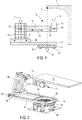
- a particle generator 1 is provided to generate radiation along a vertical axis 2 downwards.
- the positioning robot comprises a base 3 on which can rotate a linear rail 4 according to a vertical axis of rotation 5.
- this vertical axis of rotation 5 may be coincident with the axis 2 of the radiation.
- the positioning robot also comprises a junction piece 6a fixed on a base 6b pivotally along a vertical axis of rotation 7.
- the base 6b can move linearly, by translation, on the linear rail 4 along a horizontal translation axis 8.
- the junction piece 6a carries a robotic arm 9 composed of a forearm 10 and a wrist 11.
- the forearm 10 is fixed to the junction piece 6a pivotally about a horizontal axis of rotation 12.
- the forearm 10 is of sliding type so that it can lengthen linearly along a linear axis 13.
- the end of the forearm 10 furthest away from the connecting piece 6a carries the wrist 11 at three degrees of freedom along three orthogonal axes of rotation 14, 15 and 16 and concurrent.
- This wrist 11 is fixed on the sliding part of the forearm 10.
- the support table (not shown), intended to accommodate the patient, is generally fixed to the horizontal on the wrist 11.
- the positioning robot according to the invention is connected to a processing unit (not shown) able to manage the joints of this positioning robot in order to place the tumor of a patient at a predetermined position.
- This processing unit recovers in real time the articular positions of each of the axes thanks to encoders fixed to the motors. Then from the geometric parameters theoretical from the calibration of the robot, the processing unit is able to provide the user a Cartesian position of the tumor marker with respect to the virtual benchmark treatment. Thus, the user can easily interpret this position and verify that it complies with the requirement.
- the user can validate a correction to be applied to the tumor mark in the treatment mark according to the proposal of the system used for the registration of the patient (scanner, X-ray, infrared). Then, this order is analyzed and transcribed in joint control to the robot.
- the invention is furthermore provided with an advanced 3D visualization software, based on a theoretical model of the scene and the information retrieved by the various sensors present.
- This fine modeling of the positioning procedure makes it possible to consider eventually deporting orders outside the treatment room. This offset will advantageously move the positioner remotely and thus reduce the time lost by the operator to enter the room to change the incidence of treatment of the patient.
- the base 3 is constituted by a ring 3a, pivoting portion, mounted on studs 3b in aluminum profile firmly fixed to the ground.
- the linear rail 4 is a frame formed by two straight rails, pads with bearings 4a and 4b parallel, preferably steel section section "U". These two rails 4a and 4b are interconnected by three rails 4c, 4d and 4e parallel to each other and perpendicular to the two rails 4a and 4b.
- the rail 4c is disposed at one end of the linear rail assembly.
- the two rails 4c and 4d and part of the two rails 4a and 4b form a frame firmly attached to the crown 3a pivotally.
- the assembly of the linear rail 4 can rotate 360 ° along the vertical axis of rotation 5 passing through the center of the ring 3a.
- the base 6b is slidably engaged with the two rails 4a and 4b. This base 6b pivotally carries along the vertical axis of rotation 7 the junction piece 6a which is a metal frame held vertically.
- the robotic arm 9 is an arm according to the "SERIE" architecture. It is attached to an upper part of the connecting piece 6a and can pivot about the horizontal axis of rotation 12.
- the forearm 10 is an elongated and flared tube of the connection with the connecting piece 6a.
- the free end of the forearm carries the wrist 11 on which is fixed the support table 17 for the patient. This table 17 is kept substantially horizontal most of the time but it is brought to be positioned by the wrist.
- the table 17 may be a tray or chair in some cases for patient transport. It is carbon honeycomb-based to be transparent radio and very rigid while keeping a limited weight.
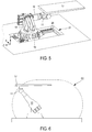
- the positioning robot is constituted such that it is compact in the rest position.
- a rest position may be the position shown on the figures 2 and 3 wherein the linear rail 4 and the forearm 10 are substantially parallel in the same vertical plane.
- the connecting piece is disposed on one end of the linear rail 4 opposite the base 3.
- the forearm 10 is fixed to the connecting piece 6a and is directed towards the base 3 while remaining parallel to the linear rail 4
- the table 17 is held above the wrist 11, one end fixed to the wrist 11, the other free end being directed away from the forearm.
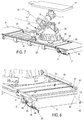
- the figure 4 is a schematic view of the working space E1 for a positioning robot according to the invention.
- This space E1 is a volume of semi-spherical shape flattened on the top. The patient can thus be positioned continuously throughout the volume of this workspace E1.
- junction piece 18 has been modified so that in this embodiment it is possible to install a high precision and high weight junction piece.
- the linear rail 21 is fixed to the ground and can easily receive a connecting piece 18 which can rotate 360 ° along an axis of vertical rotation relative to a base 19.
- This base 19 slides linearly along an axis horizontal translation on two linear rails 20 parallel and fixed to the ground.
- a small pit 21 in which are installed the first linear rail 20 and the second rail (not visible on the figure 5 ).
- This positioning robot thus has a horizontal translation axis on the linear rail and five axes of rotation: rotation of the connecting piece 18 relative to the base 19, the forearm 10 relative to the connecting piece, and the three axes of rotation of the wrist 11. It is also possible to add another translation axis because the forearm 10 can be slidable.
- the positioning robot is deployed.
- the robotic arm is in an oblique raised position.
- the wrist 11 holds the table 17 in a horizontal position.
- the working space E2 is a volume in the form of a half-sphere laterally elongate and flattened on the top.
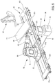
- FIG. 7 On the figure 7 is shown another advantageous embodiment of the robot according to the invention.
- a base 22 which is able to slide on two parallel linear rails 23 and 24 arranged laterally with respect to this base 22.
- a first motor 25 participates in the linear displacement of the base 22.
- a connecting piece 26, placed above of the base 22, is connected to this base 22 pivotally along a vertical axis.
- the connecting piece has a triangular shape with the base resting on the base 22 and an inclined blank receiving the robotic arm 9.
- a second motor 27 participates in the rotation of the connecting piece 26 relative to the base 22.
- the robotic arm 9 is connected to the connecting piece 26 pivotally about an axis of rotation 28 which is inclined at an angle ⁇ non-zero with respect to the horizontal.
- This angle ⁇ is preferably between 45 and 60 °. In this case, it is 60 °.
- This inclined arrangement allows the robot according to the invention to move in a reduced space such as a conventional hospital room with a ceiling limited to 2.5 meters for example, and at the same time to reach a minimum height of loading of patient of the order of 60cm, especially for the rise of a child or a senior on the plate 17.
- the inclined arrangement allows to place the robotic arm 9 and the connecting piece 26 on the base 22 the most possible near the ground without the rear portion 29 of the robotic arm 9 collides with obstacles, such as the base itself, during rotational movements. Indeed, in the preceding embodiments, the robotic arm 9 is attached to the connecting piece at a height sufficient for the rotation of the robotic arm does not intercept the base 6b for example on the figure 3 .
- the robot thus described has six axes of maneuverability, a translation and five rotations, or six degrees of freedom. We can place a patient in the workspace in any configuration.
- a floor consisting of two half-floors 30 and 31 is seen.
- the half-floor 30 is composed of several blades 32 interconnected in chains by means of articulations (visible on the figure 8 in 33).
- the half floor 30 is in the unfolded position, that is to say it is a solid flat floor on which the user can stand.
- This half-floor 30 slides in being integral with the base 22.
- the base 22 moves away from a left fixed floor 34
- the half floor 30 slides covering the pit which is between the left fixed floor 34 and the motor 25 fixed to the base 22.
- the half floor 30 slides to be placed in the folded position, in accordion, under the left fixed floor 34.
- the half floor 35 acts in the same way as the half floor 30 but in phase opposition. When one is folded, the other is unfolded, and vice versa.
- the half-floor 35 is in folded position under the right fixed floor 36. It can be seen that the blades 37 constituting the half-floor 35 are placed in accordion under the right fixed floor 36.
- Each secondary rail 38, 39 has a high linear portion 40 (not shown for the secondary rail 38) on which the blades 37 are in the unfolded position allowing the user to walk on it; a bending point 41, 42 in the shape of "S" and a linear low part 48, 43 parallel to the high linear part 40 but disposed substantially at the bottom of the pit.
- a second set of external secondary rails 44 and 45 have a spacing greater than that of the two internal secondary rails 38, 39.
- the two outer secondary rails remain linear throughout the movement of the blades 37. These blades bear at the level of the joints of the bearings arranged in staggered rows.
- Half of the bearings 46 is guided by the two internal secondary rails 38, 39, while the other half 47 is guided by the two external secondary rails 44 and 45, see figure 8 . More specifically, these bearings are alternately arranged, a bearing 46 is followed by a bearing 47 and vice versa.
- the bearings 47 slide in the external secondary rails 44 and 45, while the bearings 46 slide in the bending point 41, 42 which constitutes an access ramp to a lower level where the linear low part is located. 43, 48.
- the blades 37 are arranged vertically and accordion. They occupy a minimum volume and remain camouflaged. The blades 37 go from the horizontal state to the vertical state just with the effect of gravity, they are stored automatically and without additional motorization.
- the positioning device may be as previously described.
- the positioning device of the figure 9 comprising a junction piece 50 sliding on a linear rail 56 and carrying a robotic arm 53 having a wrist 54 with concurrent axes of rotation.
- the linear rail 56 is advantageously fixed to the ground and consists of several modular elements 57a, ..., 57d connected to each other. These modular elements can be identical so that their implementation in the treatment room is facilitated. With such an arrangement, it is thus easy to produce linear rails of different lengths.
- each modular element 57a, ..., 57d comprises a metal plate (or other solid material such as wood, plastic, ...) upper 67a, 67b, 67c placed on three uprights securely fixed to the floor, two side pillars 57h, 57i, and a central pillar 57g.
- Each upper metal plate has two grooves or lateral openings 58 and 59 on the figure 9 which are parallel and subdivide each upper metal plate into three parts 67a, 67b, 67c. These grooves give access to a confinement volume between the upper metal plates 67b and the ground.
- This containment volume contains a motor 66 on the figure 10 intended to slide the base 52 of the connecting piece 50 relative to the linear rail 56. More specifically, the base 52 is carried by pads 68 and 69. These pads comprise an upper part to support the base 52, a lower portion sliding on fixed rails 70 in the confinement volume, and a central portion shaped sufficiently narrow and solid to connect the upper part and the lower part via the grooves 58 and 59 without ever touching them.
- Such an embodiment makes it possible to camouflage the motor in an invisible confinement volume from the outside, this saves space and makes the top surface of the linear rail flat.
- the user can move safely on this floor consisting of the upper metal plates of the modular elements 57a, ..., 57d.
- the base 52 is associated with a pivot piece 51 pivotable about a vertical axis of rotation.
- the robotic arm 53 is pivotally connected to an upper portion of the junction piece 50 along an axis of rotation at an angle of between 45 and 60 degrees to the horizontal.
- the wrist 54 carries a patient support 71 which can be positioned very precisely in the repository of the treatment room.
- a processing unit 60 can electromechanically control the positioning device or robot.
- Several motors whose motor 66 for moving the linear rail are arranged on and in the robot so as to control any articulation of the robot automatically.
- a set of conventional sensors are arranged on the robot such as for example an inclinometer 65 disposed on the wrist 54. From the sensors as well as including the engines, the processing unit retrieves a set of information to know exactly in time real robot positioning. That is to say that at every moment we know the position of the support in the room and the value of the angles of inclination of the various elements of the robot.
- the processing unit includes a computer-like hardware portion with conventional elements for acquisition, analog and digital data processing.
- a hard disk 61 houses a 3D visualization module which then determines and displays on a screen 62 a 3D representation of the movement of the robot relative to the environment which is the treatment room.
- This visualization module thus comprises a virtual 3D modeling of the environment and a real-time virtual 3D modeling of the robot moving in the environment.
- it also comprises a virtual 3D modeling of a virtual envelope around the support 71 of the robot as well as a real-time collision detection algorithm between the virtual envelope and the modeled environment.
- the modeling of the environment takes into account the dimensions of the treatment room but also the elements or obstacles present in this treatment room.
- the treatment unit itself is distinguished as well as a radiation device 64 which is generally mobile.
- the processing unit is connected to the robot and the radiation device 64 wired 63 or wireless, so that the 3D viewing module can represent any mobile device in the treatment room.
- the modelizations are obtained from data acquired in real time and predetermined data. These predetermined data may correspond to the positioning data of the moving elements. These positions, like that of the processing unit, are known in advance and can be entered by the user.
- the virtual representation of the dynamics in the treatment room makes it possible to set up surveillance systems such as an anticollision process.
- figure 11 is a virtual 3D representation visible on the screen 62. Only the support 71 is shown for reasons of simplification.
- the virtual envelope 72 is of the same shape as the virtual representation of the support 71 but of greater dimensions. Consequently, when the support 71 is in motion, the envelope 72 follows the same movement and any probable collision of the support 71 with one of the elements of the treatment room is preceded by a virtual collision of the envelope 72 in the module. 3D visualization. In fact, the 3D representation makes it possible to alert the user of the real collision risk of the support 71 when the virtual envelope 72 collides with one another.
- the envelope 72 includes the 3D representation of the support 71, but this envelope 72 may be of different shape from that of the support and of smaller size, in particular to monitor only part of the support.
- 3D modeling of a virtual envelope can also be used on any mobile element of the treatment room. It is thus possible to provide a second virtual envelope around the radiation device 64, the collision being estimated between the two virtual envelopes.
- An anti-collision system makes it possible to increase the capacity of the use of a mobile system in space.
- a medical robot for example, is easily manoeuvrable by the operator safely without the need to worry about a possible contact.
- the machines are therefore more autonomous, they themselves ensure their own safety and that of those around them.
- the applied force generally comes from a user who manually moves the robot by for example pushing the patient support with his hands.
- the process of co-manipulation can be a process independent or associated with the collision avoidance technique with virtual envelope.
- the processing unit implements at the same time the collision detection.
- the sensor 65a may be a force sensor used to detect any force applied to the wrist 54.
- This type of force sensor may consist of several strain gages.
- the anticollision process allows a slow sliding of the support in the volume of the virtual envelope. This principle allows in co-manipulation mode to avoid untimely stops of the robot and to smooth the trajectories in the vicinity of elements present in the treatment room. Sliding is also an aid to the manipulation and manual guidance of the robot.
Landscapes
- Health & Medical Sciences (AREA)
- Engineering & Computer Science (AREA)
- Biomedical Technology (AREA)
- Life Sciences & Earth Sciences (AREA)
- Nuclear Medicine, Radiotherapy & Molecular Imaging (AREA)
- Radiology & Medical Imaging (AREA)
- Pathology (AREA)
- Animal Behavior & Ethology (AREA)
- General Health & Medical Sciences (AREA)
- Public Health (AREA)
- Veterinary Medicine (AREA)
- Radiation-Therapy Devices (AREA)
- Manipulator (AREA)
- Accommodation For Nursing Or Treatment Tables (AREA)
- Apparatus For Radiation Diagnosis (AREA)
Priority Applications (1)
| Application Number | Priority Date | Filing Date | Title |
|---|---|---|---|
| PL09763988T PL2376012T3 (pl) | 2008-10-31 | 2009-10-30 | Urządzenie do pozycjonowania pacjenta względem promieniowania |
Applications Claiming Priority (2)
| Application Number | Priority Date | Filing Date | Title |
|---|---|---|---|
| FR0857442A FR2937854B1 (fr) | 2008-10-31 | 2008-10-31 | Dispositif pour positionner un patient par rapport a un rayonnement. |
| PCT/FR2009/052103 WO2010049660A2 (fr) | 2008-10-31 | 2009-10-30 | Dispositif pour positionner un patient par rapport à un rayonnement |
Publications (2)
| Publication Number | Publication Date |
|---|---|
| EP2376012A2 EP2376012A2 (fr) | 2011-10-19 |
| EP2376012B1 true EP2376012B1 (fr) | 2016-09-07 |
Family
ID=40750783
Family Applications (1)
| Application Number | Title | Priority Date | Filing Date |
|---|---|---|---|
| EP09763988.4A Not-in-force EP2376012B1 (fr) | 2008-10-31 | 2009-10-30 | Dispositif pour positionner un patient par rapport à un rayonnement |
Country Status (9)
Families Citing this family (56)
| Publication number | Priority date | Publication date | Assignee | Title |
|---|---|---|---|---|
| US9498167B2 (en) | 2005-04-29 | 2016-11-22 | Varian Medical Systems, Inc. | System and methods for treating patients using radiation |
| CN102166750B (zh) * | 2011-05-16 | 2014-01-29 | 机械科学研究总院先进制造技术研究中心 | 定位梁及具有该定位梁的机器人直线运动单元 |
| JP5653897B2 (ja) * | 2011-12-27 | 2015-01-14 | 住友重機械工業株式会社 | 中性子線照射用患者治療台及び中性子線照射装置 |
| JP2013169289A (ja) * | 2012-02-20 | 2013-09-02 | Mitsubishi Heavy Ind Ltd | 患者傾動装置付きカウチ |
| DE102012203767A1 (de) * | 2012-03-09 | 2013-07-04 | Siemens Aktiengesellschaft | Positionierungshilfe für eine verfahrbare Gantry |
| JP2014128352A (ja) * | 2012-12-28 | 2014-07-10 | Mitsubishi Electric Corp | 放射線治療装置の衝突防止インターロック装置及び放射線治療システム |
| HRP20201750T1 (hr) * | 2013-06-07 | 2020-12-25 | Francesco AUTELLI | Uređaj za premještanje ljudi i / ili robe na ili sa broda |
| US9918885B2 (en) * | 2013-09-04 | 2018-03-20 | Tyrone Soklaski | Remote control for scooter lift |
| GB2519592B (en) * | 2013-10-28 | 2020-01-29 | Elekta Ab | Radiotherapy apparatus with a tiltable gantry arm |
| KR101652575B1 (ko) * | 2014-02-14 | 2016-08-30 | 인제대학교 산학협력단 | 선형가속기기반 방사선 수술장비의 방사선 분포측정기 정밀 조종장치 |
| USD768295S1 (en) * | 2014-03-17 | 2016-10-04 | Intuitive Surgical Operations, Inc. | Surgical instrument end portion |
| USD760387S1 (en) * | 2014-03-17 | 2016-06-28 | Intuitive Surgical Operations, Inc. | Surgical instrument end portion |
| USD767129S1 (en) * | 2014-03-17 | 2016-09-20 | Intuitive Surgical Operations, Inc. | Surgical instrument end portion |
| USD767130S1 (en) * | 2014-03-17 | 2016-09-20 | Intuitive Surgical Operations, Inc. | Surgical instrument end portion |
| JP6223882B2 (ja) * | 2014-03-18 | 2017-11-01 | 住友重機械工業株式会社 | 中性子捕捉療法システム |
| EP2944259A1 (de) * | 2014-05-15 | 2015-11-18 | Buck Engineering & Consulting GmbH | Patientenpositioniereinrichtung |
| JP6282562B2 (ja) * | 2014-09-05 | 2018-02-21 | 住友重機械工業株式会社 | 中性子線捕捉療法システム |
| JP6326364B2 (ja) * | 2014-12-24 | 2018-05-16 | 株式会社日立製作所 | 治療台、位置決めシステムならびにその運転方法 |
| US9933013B2 (en) * | 2015-02-18 | 2018-04-03 | Aesynt Incorporated | Alignment meter for a rail system |
| DE102015003239A1 (de) * | 2015-03-10 | 2016-09-15 | Beumer Gmbh & Co. Kg | Vorrichtung zum Be- oder Entladen einen Transportbehälters |
| CN105184813B (zh) * | 2015-07-22 | 2018-06-22 | 广西大学 | 一种运动物体二维轨迹追踪机构 |
| CN105079986B (zh) * | 2015-09-07 | 2017-12-12 | 四川大学 | 一种非共面放射治疗系统 |
| JP6590946B2 (ja) | 2015-12-11 | 2019-10-16 | 株式会社メディカロイド | 医療システム |
| DE102016210497A1 (de) * | 2016-06-14 | 2017-12-14 | Kuka Roboter Gmbh | Patientenpositioniervorrichtung und medizinischer Arbeitsplatz |
| DE102016211538A1 (de) * | 2016-06-27 | 2017-12-28 | Leoni Kabel Gmbh | Roboter und Roboteranordnung zur Patientenpositionierung |
| CN107617168A (zh) * | 2016-07-13 | 2018-01-23 | 瑞地玛医学科技有限公司 | 一种治疗床移载装置 |
| USD865164S1 (en) | 2016-07-14 | 2019-10-29 | Intuitive Surgical Operations, Inc. | Surgical instrument actuator end portion |
| USD864386S1 (en) | 2016-07-14 | 2019-10-22 | Intuitive Surgical Operations, Inc. | Surgical instrument actuator end portion |
| USD865163S1 (en) | 2016-07-14 | 2019-10-29 | Intuitive Surgical Operations, Inc. | Surgical instrument actuator end portion |
| US10980692B2 (en) * | 2016-08-29 | 2021-04-20 | Mobius Imaging, Llc | Table system for medical imaging |
| US10806409B2 (en) | 2016-09-23 | 2020-10-20 | Varian Medical Systems International Ag | Medical systems with patient supports |
| JP6270957B1 (ja) * | 2016-10-26 | 2018-01-31 | 株式会社メディカロイド | ロボット手術台 |
| JP6216858B1 (ja) * | 2016-10-26 | 2017-10-18 | 株式会社メディカロイド | ロボット手術台 |
| CN117339120A (zh) | 2016-11-15 | 2024-01-05 | 反射医疗公司 | 用于发射引导式高能光子传输的系统 |
| EP4464251A3 (en) * | 2016-11-15 | 2025-02-19 | RefleXion Medical, Inc. | Radiation therapy patient platform |
| CN110099718A (zh) * | 2016-12-23 | 2019-08-06 | 皇家飞利浦有限公司 | 用于检测和避免辐射治疗设备与患者之间的碰撞的射线跟踪 |
| JP6563891B2 (ja) * | 2016-12-28 | 2019-08-21 | 株式会社メディカロイド | ロボット手術台およびハイブリッド手術室 |
| CN108245357B (zh) * | 2016-12-28 | 2020-07-14 | 美好罗伯特有限公司 | 机械手术台以及混合手术室系统 |
| JP6800058B2 (ja) * | 2017-03-23 | 2020-12-16 | 株式会社メディカロイド | 患者載置用テーブルの移動方法 |
| US11058895B2 (en) * | 2017-08-15 | 2021-07-13 | Daegu Gyeongbuk Institute Of Science And Technology | Collimator and medical robot including the same |
| CN108030522B (zh) * | 2017-12-21 | 2020-07-10 | 辽宁省肿瘤医院 | 一种盆腔手术多功能牵开器 |
| CN108209967A (zh) * | 2018-01-05 | 2018-06-29 | 柴丽 | 一种超声科检查用患者肢体多角度调节装置 |
| WO2019160958A1 (en) | 2018-02-13 | 2019-08-22 | Reflexion Medical, Inc. | Beam station treatment planning and radiation delivery methods |
| USD884892S1 (en) | 2018-04-20 | 2020-05-19 | Intuitive Surgical Operations, Inc. | Surgical instrument backend housing |
| BR112021003450A2 (pt) * | 2018-08-24 | 2021-05-18 | Medical Beam Laboratories, Llc | sistema de posicionamento do paciente, aparelho de distribuição de um feixe de radiação, processo de distribuição de uma dose terapêutica de radiação a um paciente humano ou animal, e aparelho de posicionamento do paciente |
| CN109739268B (zh) * | 2018-12-18 | 2021-11-16 | 深圳市太赫兹科技创新研究院 | 成像调节装置 |
| US11315751B2 (en) * | 2019-04-25 | 2022-04-26 | The Boeing Company | Electromagnetic X-ray control |
| CN110354397A (zh) * | 2019-07-20 | 2019-10-22 | 中广核戈瑞(深圳)科技有限公司 | 可方便实现辐照高度及角度调节的辐照照射仪 |
| CN113018695A (zh) * | 2019-12-24 | 2021-06-25 | 中硼(厦门)医疗器械有限公司 | 放射线照射系统 |
| CN112137361B (zh) * | 2020-09-29 | 2022-08-23 | 江苏苏宁银行股份有限公司 | 一种多功能组装式银行营业柜台 |
| JP6899172B1 (ja) * | 2021-03-10 | 2021-07-07 | 株式会社ビードットメディカル | 患者搬送台車及び粒子線照射システム |
| WO2022240894A1 (en) * | 2021-05-11 | 2022-11-17 | Celestial Oncology Inc. | Coupled robotic radiation therapy system |
| CN113663235A (zh) * | 2021-09-26 | 2021-11-19 | 合肥中科离子医学技术装备有限公司 | 放射治疗用的摆位设备 |
| US20250050135A1 (en) * | 2021-12-21 | 2025-02-13 | Elekta Beijing Medical Systems Co., Ltd. | Patient positioning apparatus for a radiotherapy system |
| JP2024005322A (ja) * | 2022-06-30 | 2024-01-17 | 川崎重工業株式会社 | ロボットシステムおよびロボット |
| CN116714016B (zh) * | 2023-05-16 | 2025-07-18 | 湖南大学 | 一种辐射环境下机器人关节模组测控平台 |
Family Cites Families (16)
| Publication number | Priority date | Publication date | Assignee | Title |
|---|---|---|---|---|
| JP2578541B2 (ja) * | 1991-12-13 | 1997-02-05 | 三菱電機株式会社 | 放射線治療装置 |
| JP3577221B2 (ja) * | 1997-08-04 | 2004-10-13 | 住友重機械工業株式会社 | 放射線治療用ベッドシステム |
| US6094760A (en) * | 1997-08-04 | 2000-08-01 | Sumitomo Heavy Industries, Ltd. | Bed system for radiation therapy |
| JP2002253687A (ja) * | 2001-03-02 | 2002-09-10 | Mitsubishi Heavy Ind Ltd | 放射線医療装置 |
| EP1419801B1 (en) * | 2001-08-24 | 2010-11-03 | Mitsubishi Heavy Industries, Ltd. | Radiotherapeutic device |
| CA2495675C (en) * | 2002-09-06 | 2012-12-18 | Hill-Rom Services, Inc. | Hospital bed |
| US8160205B2 (en) * | 2004-04-06 | 2012-04-17 | Accuray Incorporated | Robotic arm for patient positioning assembly |
| US7837674B2 (en) * | 2005-01-24 | 2010-11-23 | Intuitive Surgical Operations, Inc. | Compact counter balance for robotic surgical systems |
| EP1749550A1 (en) | 2005-08-04 | 2007-02-07 | Institut Curie | Method and apparatus for applying radiotherapy |
| DE102005054222A1 (de) * | 2005-11-14 | 2007-05-16 | Maquet Gmbh & Co Kg | Operationstisch |
| WO2007112602A1 (de) * | 2006-03-31 | 2007-10-11 | Schär Engineering Ag | Verfahren und vorrichtung zum heben und senken sowie drehen und horizontalen verfahren einer patientenliege |
| US20080021300A1 (en) * | 2006-06-29 | 2008-01-24 | Allison John W | Four-dimensional target modeling and radiation treatment |
| WO2008110170A1 (en) * | 2007-03-09 | 2008-09-18 | NRT-Nordisk Røntgen Teknik A/S | Examination table |
| US20090044334A1 (en) * | 2007-08-13 | 2009-02-19 | Valence Broadband, Inc. | Automatically adjusting patient platform support height in response to patient related events |
| CN201115704Y (zh) * | 2007-11-27 | 2008-09-17 | 王智 | 放射科用平台 |
| US8521331B2 (en) * | 2009-11-13 | 2013-08-27 | Intuitive Surgical Operations, Inc. | Patient-side surgeon interface for a minimally invasive, teleoperated surgical instrument |
-
2008
- 2008-10-31 FR FR0857442A patent/FR2937854B1/fr not_active Expired - Fee Related
-
2009
- 2009-10-30 JP JP2011533796A patent/JP5623415B2/ja not_active Expired - Fee Related
- 2009-10-30 CN CN2009801519200A patent/CN102256562A/zh active Pending
- 2009-10-30 EP EP09763988.4A patent/EP2376012B1/fr not_active Not-in-force
- 2009-10-30 WO PCT/FR2009/052103 patent/WO2010049660A2/fr active Application Filing
- 2009-10-30 ES ES09763988.4T patent/ES2604540T3/es active Active
- 2009-10-30 US US12/665,276 patent/US8740880B2/en active Active
- 2009-10-30 PL PL09763988T patent/PL2376012T3/pl unknown
-
2011
- 2011-05-01 IL IL212607A patent/IL212607A0/en unknown
Also Published As
| Publication number | Publication date |
|---|---|
| JP2012506748A (ja) | 2012-03-22 |
| PL2376012T3 (pl) | 2017-07-31 |
| FR2937854A1 (fr) | 2010-05-07 |
| CN102256562A (zh) | 2011-11-23 |
| US20110066278A1 (en) | 2011-03-17 |
| WO2010049660A2 (fr) | 2010-05-06 |
| US8740880B2 (en) | 2014-06-03 |
| ES2604540T3 (es) | 2017-03-07 |
| EP2376012A2 (fr) | 2011-10-19 |
| JP5623415B2 (ja) | 2014-11-12 |
| WO2010049660A3 (fr) | 2010-07-29 |
| IL212607A0 (en) | 2011-07-31 |
| FR2937854B1 (fr) | 2010-12-03 |
Similar Documents
| Publication | Publication Date | Title |
|---|---|---|
| EP2376012B1 (fr) | Dispositif pour positionner un patient par rapport à un rayonnement | |
| EP2032066B1 (fr) | Installation robotisee pour le positionnement et le deplacement d'un organe ou instrument et appareil de traitement comprenant une telle installation | |
| EP1497836B1 (fr) | Paravent de protection contre les emissions de rayonnements ionisants | |
| WO2011073599A1 (fr) | Systeme anticollision pour le deplacement d'un objet dans un environnement encombre | |
| CN104837408B (zh) | 用于锥形束计算机断层摄影的肢体成像装置 | |
| FR2953119A1 (fr) | Base mobile et appareil a rayons x monte sur une telle base mobile | |
| US10206749B2 (en) | Articulating camera stand | |
| FR2847452A1 (fr) | Procede et appareil pour eviter des collisions dans une plate-forme de positionnement de patient | |
| FR3016821B1 (fr) | Exosquelette a port frontal et procede d'utilisation d'un tel exosquelette. | |
| EP0197020A1 (fr) | Véhicule télécommandé pour inspection et intervention en milieux hostiles | |
| CA2841177A1 (fr) | Systeme robotise pour le deplacement d'un outil guide a distance | |
| WO2011080460A1 (fr) | Appareil de radiologie dentaire fournissant une image cephalometrique et procede associe | |
| WO2009156660A2 (fr) | Perfectionnement aux paravents de protection contre les emissions de rayonnements ionisants | |
| CN1932492B (zh) | X光检查装置 | |
| FR3028168A1 (fr) | Appareil de tomographie numerique et procede associe | |
| FR3120385A1 (fr) | Dispositif d'aide à la pose de voussoirs | |
| EP4175581B1 (fr) | Dispositif robotique pour le guidage d'un bras robotise | |
| US9097538B1 (en) | Rover | |
| FR3026335A1 (fr) | Exosquelette avec porte outil et procede d'utilisation d'un tel exosquelette. | |
| WO2008132324A1 (fr) | Dispositif de mesure et de correction de la lateropulsion | |
| EP2377466A1 (fr) | Aparreil de traitement par ondes de pression, équipé d'un système pour déplacer l'arceau d'un système d'imagerie par rayons X | |
| JP2005297100A (ja) | ロボット用マニピュレータ | |
| FR2960938A1 (fr) | Support d'ecran | |
| Altschuler et al. | Rapid 3D video/laser sensing and digital archiving with immediate on-scene feedback for 3D crime scene/mass disaster data collection and reconstruction | |
| FR3138060A1 (fr) | Dispositif et methode de mesure anthropometrique d’ajustment et de configuration d’un exosquelette |
Legal Events
| Date | Code | Title | Description |
|---|---|---|---|
| PUAI | Public reference made under article 153(3) epc to a published international application that has entered the european phase |
Free format text: ORIGINAL CODE: 0009012 |
|
| 17P | Request for examination filed |
Effective date: 20110530 |
|
| AK | Designated contracting states |
Kind code of ref document: A2 Designated state(s): AT BE BG CH CY CZ DE DK EE ES FI FR GB GR HR HU IE IS IT LI LT LU LV MC MK MT NL NO PL PT RO SE SI SK SM TR |
|
| DAX | Request for extension of the european patent (deleted) | ||
| RAP1 | Party data changed (applicant data changed or rights of an application transferred) |
Owner name: INSTITUT CURIE Owner name: BUREAU FRANCAIS D'INGENIERIE |
|
| 17Q | First examination report despatched |
Effective date: 20130125 |
|
| REG | Reference to a national code |
Ref country code: DE Ref legal event code: R079 Ref document number: 602009040987 Country of ref document: DE Free format text: PREVIOUS MAIN CLASS: A61B0019000000 Ipc: A61N0005100000 |
|
| GRAP | Despatch of communication of intention to grant a patent |
Free format text: ORIGINAL CODE: EPIDOSNIGR1 |
|
| RIC1 | Information provided on ipc code assigned before grant |
Ipc: A61N 5/10 20060101AFI20160223BHEP |
|
| INTG | Intention to grant announced |
Effective date: 20160323 |
|
| RIN1 | Information on inventor provided before grant (corrected) |
Inventor name: PINAULT, SAMUEL Inventor name: FERRAND, REGIS Inventor name: CHEMOUNY, JEROME |
|
| GRAS | Grant fee paid |
Free format text: ORIGINAL CODE: EPIDOSNIGR3 |
|
| GRAA | (expected) grant |
Free format text: ORIGINAL CODE: 0009210 |
|
| AK | Designated contracting states |
Kind code of ref document: B1 Designated state(s): AT BE BG CH CY CZ DE DK EE ES FI FR GB GR HR HU IE IS IT LI LT LU LV MC MK MT NL NO PL PT RO SE SI SK SM TR |
|
| REG | Reference to a national code |
Ref country code: GB Ref legal event code: FG4D Free format text: NOT ENGLISH |
|
| REG | Reference to a national code |
Ref country code: CH Ref legal event code: EP |
|
| REG | Reference to a national code |
Ref country code: IE Ref legal event code: FG4D Free format text: LANGUAGE OF EP DOCUMENT: FRENCH |
|
| REG | Reference to a national code |
Ref country code: AT Ref legal event code: REF Ref document number: 826299 Country of ref document: AT Kind code of ref document: T Effective date: 20161015 |
|
| REG | Reference to a national code |
Ref country code: DE Ref legal event code: R096 Ref document number: 602009040987 Country of ref document: DE |
|
| REG | Reference to a national code |
Ref country code: FR Ref legal event code: PLFP Year of fee payment: 8 |
|
| REG | Reference to a national code |
Ref country code: RO Ref legal event code: EPE |
|
| REG | Reference to a national code |
Ref country code: NL Ref legal event code: FP |
|
| REG | Reference to a national code |
Ref country code: LT Ref legal event code: MG4D |
|
| PG25 | Lapsed in a contracting state [announced via postgrant information from national office to epo] |
Ref country code: NO Free format text: LAPSE BECAUSE OF FAILURE TO SUBMIT A TRANSLATION OF THE DESCRIPTION OR TO PAY THE FEE WITHIN THE PRESCRIBED TIME-LIMIT Effective date: 20161207 Ref country code: HR Free format text: LAPSE BECAUSE OF FAILURE TO SUBMIT A TRANSLATION OF THE DESCRIPTION OR TO PAY THE FEE WITHIN THE PRESCRIBED TIME-LIMIT Effective date: 20160907 Ref country code: FI Free format text: LAPSE BECAUSE OF FAILURE TO SUBMIT A TRANSLATION OF THE DESCRIPTION OR TO PAY THE FEE WITHIN THE PRESCRIBED TIME-LIMIT Effective date: 20160907 Ref country code: LT Free format text: LAPSE BECAUSE OF FAILURE TO SUBMIT A TRANSLATION OF THE DESCRIPTION OR TO PAY THE FEE WITHIN THE PRESCRIBED TIME-LIMIT Effective date: 20160907 |
|
| REG | Reference to a national code |
Ref country code: AT Ref legal event code: MK05 Ref document number: 826299 Country of ref document: AT Kind code of ref document: T Effective date: 20160907 |
|
| PG25 | Lapsed in a contracting state [announced via postgrant information from national office to epo] |
Ref country code: SE Free format text: LAPSE BECAUSE OF FAILURE TO SUBMIT A TRANSLATION OF THE DESCRIPTION OR TO PAY THE FEE WITHIN THE PRESCRIBED TIME-LIMIT Effective date: 20160907 Ref country code: LV Free format text: LAPSE BECAUSE OF FAILURE TO SUBMIT A TRANSLATION OF THE DESCRIPTION OR TO PAY THE FEE WITHIN THE PRESCRIBED TIME-LIMIT Effective date: 20160907 Ref country code: BE Free format text: LAPSE BECAUSE OF NON-PAYMENT OF DUE FEES Effective date: 20161031 Ref country code: GR Free format text: LAPSE BECAUSE OF FAILURE TO SUBMIT A TRANSLATION OF THE DESCRIPTION OR TO PAY THE FEE WITHIN THE PRESCRIBED TIME-LIMIT Effective date: 20161208 |
|
| REG | Reference to a national code |
Ref country code: ES Ref legal event code: FG2A Ref document number: 2604540 Country of ref document: ES Kind code of ref document: T3 Effective date: 20170307 |
|
| PG25 | Lapsed in a contracting state [announced via postgrant information from national office to epo] |
Ref country code: EE Free format text: LAPSE BECAUSE OF FAILURE TO SUBMIT A TRANSLATION OF THE DESCRIPTION OR TO PAY THE FEE WITHIN THE PRESCRIBED TIME-LIMIT Effective date: 20160907 |
|
| PG25 | Lapsed in a contracting state [announced via postgrant information from national office to epo] |
Ref country code: SK Free format text: LAPSE BECAUSE OF FAILURE TO SUBMIT A TRANSLATION OF THE DESCRIPTION OR TO PAY THE FEE WITHIN THE PRESCRIBED TIME-LIMIT Effective date: 20160907 Ref country code: PT Free format text: LAPSE BECAUSE OF FAILURE TO SUBMIT A TRANSLATION OF THE DESCRIPTION OR TO PAY THE FEE WITHIN THE PRESCRIBED TIME-LIMIT Effective date: 20170109 Ref country code: BG Free format text: LAPSE BECAUSE OF FAILURE TO SUBMIT A TRANSLATION OF THE DESCRIPTION OR TO PAY THE FEE WITHIN THE PRESCRIBED TIME-LIMIT Effective date: 20161207 Ref country code: CZ Free format text: LAPSE BECAUSE OF FAILURE TO SUBMIT A TRANSLATION OF THE DESCRIPTION OR TO PAY THE FEE WITHIN THE PRESCRIBED TIME-LIMIT Effective date: 20160907 Ref country code: IS Free format text: LAPSE BECAUSE OF FAILURE TO SUBMIT A TRANSLATION OF THE DESCRIPTION OR TO PAY THE FEE WITHIN THE PRESCRIBED TIME-LIMIT Effective date: 20170107 Ref country code: AT Free format text: LAPSE BECAUSE OF FAILURE TO SUBMIT A TRANSLATION OF THE DESCRIPTION OR TO PAY THE FEE WITHIN THE PRESCRIBED TIME-LIMIT Effective date: 20160907 Ref country code: SM Free format text: LAPSE BECAUSE OF FAILURE TO SUBMIT A TRANSLATION OF THE DESCRIPTION OR TO PAY THE FEE WITHIN THE PRESCRIBED TIME-LIMIT Effective date: 20160907 |
|
| REG | Reference to a national code |
Ref country code: CH Ref legal event code: PL |
|
| REG | Reference to a national code |
Ref country code: DE Ref legal event code: R097 Ref document number: 602009040987 Country of ref document: DE |
|
| PLBE | No opposition filed within time limit |
Free format text: ORIGINAL CODE: 0009261 |
|
| STAA | Information on the status of an ep patent application or granted ep patent |
Free format text: STATUS: NO OPPOSITION FILED WITHIN TIME LIMIT |
|
| REG | Reference to a national code |
Ref country code: IE Ref legal event code: MM4A |
|
| PG25 | Lapsed in a contracting state [announced via postgrant information from national office to epo] |
Ref country code: DK Free format text: LAPSE BECAUSE OF FAILURE TO SUBMIT A TRANSLATION OF THE DESCRIPTION OR TO PAY THE FEE WITHIN THE PRESCRIBED TIME-LIMIT Effective date: 20160907 Ref country code: LI Free format text: LAPSE BECAUSE OF NON-PAYMENT OF DUE FEES Effective date: 20161031 Ref country code: CH Free format text: LAPSE BECAUSE OF NON-PAYMENT OF DUE FEES Effective date: 20161031 |
|
| 26N | No opposition filed |
Effective date: 20170608 |
|
| PG25 | Lapsed in a contracting state [announced via postgrant information from national office to epo] |
Ref country code: SI Free format text: LAPSE BECAUSE OF FAILURE TO SUBMIT A TRANSLATION OF THE DESCRIPTION OR TO PAY THE FEE WITHIN THE PRESCRIBED TIME-LIMIT Effective date: 20160907 Ref country code: LU Free format text: LAPSE BECAUSE OF NON-PAYMENT OF DUE FEES Effective date: 20161030 |
|
| REG | Reference to a national code |
Ref country code: FR Ref legal event code: PLFP Year of fee payment: 9 |
|
| PG25 | Lapsed in a contracting state [announced via postgrant information from national office to epo] |
Ref country code: IE Free format text: LAPSE BECAUSE OF NON-PAYMENT OF DUE FEES Effective date: 20161030 |
|
| REG | Reference to a national code |
Ref country code: BE Ref legal event code: MM Effective date: 20161031 |
|
| PGFP | Annual fee paid to national office [announced via postgrant information from national office to epo] |
Ref country code: RO Payment date: 20171013 Year of fee payment: 9 |
|
| PG25 | Lapsed in a contracting state [announced via postgrant information from national office to epo] |
Ref country code: CY Free format text: LAPSE BECAUSE OF FAILURE TO SUBMIT A TRANSLATION OF THE DESCRIPTION OR TO PAY THE FEE WITHIN THE PRESCRIBED TIME-LIMIT Effective date: 20160907 Ref country code: HU Free format text: LAPSE BECAUSE OF FAILURE TO SUBMIT A TRANSLATION OF THE DESCRIPTION OR TO PAY THE FEE WITHIN THE PRESCRIBED TIME-LIMIT; INVALID AB INITIO Effective date: 20091030 |
|
| PG25 | Lapsed in a contracting state [announced via postgrant information from national office to epo] |
Ref country code: MK Free format text: LAPSE BECAUSE OF FAILURE TO SUBMIT A TRANSLATION OF THE DESCRIPTION OR TO PAY THE FEE WITHIN THE PRESCRIBED TIME-LIMIT Effective date: 20160907 Ref country code: MC Free format text: LAPSE BECAUSE OF FAILURE TO SUBMIT A TRANSLATION OF THE DESCRIPTION OR TO PAY THE FEE WITHIN THE PRESCRIBED TIME-LIMIT Effective date: 20160907 Ref country code: MT Free format text: LAPSE BECAUSE OF FAILURE TO SUBMIT A TRANSLATION OF THE DESCRIPTION OR TO PAY THE FEE WITHIN THE PRESCRIBED TIME-LIMIT Effective date: 20160907 |
|
| REG | Reference to a national code |
Ref country code: FR Ref legal event code: PLFP Year of fee payment: 10 |
|
| PGFP | Annual fee paid to national office [announced via postgrant information from national office to epo] |
Ref country code: GB Payment date: 20181227 Year of fee payment: 15 |
|
| PG25 | Lapsed in a contracting state [announced via postgrant information from national office to epo] |
Ref country code: RO Free format text: LAPSE BECAUSE OF NON-PAYMENT OF DUE FEES Effective date: 20181030 |
|
| PGFP | Annual fee paid to national office [announced via postgrant information from national office to epo] |
Ref country code: NL Payment date: 20201028 Year of fee payment: 12 |
|
| PGFP | Annual fee paid to national office [announced via postgrant information from national office to epo] |
Ref country code: IT Payment date: 20201026 Year of fee payment: 12 Ref country code: ES Payment date: 20201228 Year of fee payment: 12 Ref country code: DE Payment date: 20201022 Year of fee payment: 12 |
|
| PGFP | Annual fee paid to national office [announced via postgrant information from national office to epo] |
Ref country code: PL Payment date: 20201022 Year of fee payment: 12 |
|
| REG | Reference to a national code |
Ref country code: DE Ref legal event code: R119 Ref document number: 602009040987 Country of ref document: DE |
|
| REG | Reference to a national code |
Ref country code: NL Ref legal event code: MM Effective date: 20211101 |
|
| PG25 | Lapsed in a contracting state [announced via postgrant information from national office to epo] |
Ref country code: TR Free format text: LAPSE BECAUSE OF NON-PAYMENT OF DUE FEES Effective date: 20191030 |
|
| PG25 | Lapsed in a contracting state [announced via postgrant information from national office to epo] |
Ref country code: NL Free format text: LAPSE BECAUSE OF NON-PAYMENT OF DUE FEES Effective date: 20211101 Ref country code: DE Free format text: LAPSE BECAUSE OF NON-PAYMENT OF DUE FEES Effective date: 20220503 |
|
| PG25 | Lapsed in a contracting state [announced via postgrant information from national office to epo] |
Ref country code: IT Free format text: LAPSE BECAUSE OF NON-PAYMENT OF DUE FEES Effective date: 20211030 |
|
| REG | Reference to a national code |
Ref country code: ES Ref legal event code: FD2A Effective date: 20230222 |
|
| PG25 | Lapsed in a contracting state [announced via postgrant information from national office to epo] |
Ref country code: ES Free format text: LAPSE BECAUSE OF NON-PAYMENT OF DUE FEES Effective date: 20211031 |
|
| PG25 | Lapsed in a contracting state [announced via postgrant information from national office to epo] |
Ref country code: PL Free format text: LAPSE BECAUSE OF NON-PAYMENT OF DUE FEES Effective date: 20211030 |
|
| PGFP | Annual fee paid to national office [announced via postgrant information from national office to epo] |
Ref country code: GB Payment date: 20231030 Year of fee payment: 15 |
|
| PGFP | Annual fee paid to national office [announced via postgrant information from national office to epo] |
Ref country code: FR Payment date: 20231027 Year of fee payment: 15 |
|
| GBPC | Gb: european patent ceased through non-payment of renewal fee |
Effective date: 20241030 |
|
| PG25 | Lapsed in a contracting state [announced via postgrant information from national office to epo] |
Ref country code: GB Free format text: LAPSE BECAUSE OF NON-PAYMENT OF DUE FEES Effective date: 20241030 |
|
| PG25 | Lapsed in a contracting state [announced via postgrant information from national office to epo] |
Ref country code: FR Free format text: LAPSE BECAUSE OF NON-PAYMENT OF DUE FEES Effective date: 20241031 |