EP2376012B1 - Device for positioning a patient relative to a radiation - Google Patents
Device for positioning a patient relative to a radiation Download PDFInfo
- Publication number
- EP2376012B1 EP2376012B1 EP09763988.4A EP09763988A EP2376012B1 EP 2376012 B1 EP2376012 B1 EP 2376012B1 EP 09763988 A EP09763988 A EP 09763988A EP 2376012 B1 EP2376012 B1 EP 2376012B1
- Authority
- EP
- European Patent Office
- Prior art keywords
- positioning
- robot
- secondary rails
- axis
- patient
- Prior art date
- Legal status (The legal status is an assumption and is not a legal conclusion. Google has not performed a legal analysis and makes no representation as to the accuracy of the status listed.)
- Active
Links
- 230000005855 radiation Effects 0.000 title claims description 14
- 238000011282 treatment Methods 0.000 claims description 39
- 210000000707 wrist Anatomy 0.000 claims description 21
- 238000012545 processing Methods 0.000 claims description 20
- 238000000034 method Methods 0.000 claims description 15
- 238000013519 translation Methods 0.000 claims description 15
- 230000014616 translation Effects 0.000 claims description 15
- 210000000245 forearm Anatomy 0.000 claims description 14
- 238000009434 installation Methods 0.000 claims description 8
- 230000008569 process Effects 0.000 claims description 8
- 238000006073 displacement reaction Methods 0.000 claims description 7
- 230000004044 response Effects 0.000 claims description 2
- 206010028980 Neoplasm Diseases 0.000 description 9
- 238000001959 radiotherapy Methods 0.000 description 8
- 238000004422 calculation algorithm Methods 0.000 description 7
- 229910052751 metal Inorganic materials 0.000 description 6
- 239000002184 metal Substances 0.000 description 6
- 238000012800 visualization Methods 0.000 description 6
- 238000001514 detection method Methods 0.000 description 5
- 238000005259 measurement Methods 0.000 description 5
- 238000005452 bending Methods 0.000 description 3
- 230000008859 change Effects 0.000 description 3
- 230000005484 gravity Effects 0.000 description 3
- 229910000831 Steel Inorganic materials 0.000 description 2
- 229910052782 aluminium Inorganic materials 0.000 description 2
- XAGFODPZIPBFFR-UHFFFAOYSA-N aluminium Chemical compound [Al] XAGFODPZIPBFFR-UHFFFAOYSA-N 0.000 description 2
- 230000003416 augmentation Effects 0.000 description 2
- 230000007547 defect Effects 0.000 description 2
- 230000000694 effects Effects 0.000 description 2
- 230000007246 mechanism Effects 0.000 description 2
- 239000002245 particle Substances 0.000 description 2
- 238000013138 pruning Methods 0.000 description 2
- 239000007787 solid Substances 0.000 description 2
- 239000010959 steel Substances 0.000 description 2
- OKTJSMMVPCPJKN-UHFFFAOYSA-N Carbon Chemical group [C] OKTJSMMVPCPJKN-UHFFFAOYSA-N 0.000 description 1
- 241000238631 Hexapoda Species 0.000 description 1
- 230000009471 action Effects 0.000 description 1
- 210000000133 brain stem Anatomy 0.000 description 1
- 238000004364 calculation method Methods 0.000 description 1
- 229910052799 carbon Inorganic materials 0.000 description 1
- 238000012937 correction Methods 0.000 description 1
- 230000008878 coupling Effects 0.000 description 1
- 238000010168 coupling process Methods 0.000 description 1
- 238000005859 coupling reaction Methods 0.000 description 1
- 210000003027 ear inner Anatomy 0.000 description 1
- 239000012636 effector Substances 0.000 description 1
- 238000000605 extraction Methods 0.000 description 1
- 210000004247 hand Anatomy 0.000 description 1
- 210000003128 head Anatomy 0.000 description 1
- 238000003384 imaging method Methods 0.000 description 1
- 238000007917 intracranial administration Methods 0.000 description 1
- 230000005865 ionizing radiation Effects 0.000 description 1
- 230000003211 malignant effect Effects 0.000 description 1
- 201000001441 melanoma Diseases 0.000 description 1
- 230000004048 modification Effects 0.000 description 1
- 238000012986 modification Methods 0.000 description 1
- 210000001328 optic nerve Anatomy 0.000 description 1
- 238000005457 optimization Methods 0.000 description 1
- 210000000056 organ Anatomy 0.000 description 1
- 230000009467 reduction Effects 0.000 description 1
- 238000009877 rendering Methods 0.000 description 1
- 230000000284 resting effect Effects 0.000 description 1
- 238000007493 shaping process Methods 0.000 description 1
- 238000004088 simulation Methods 0.000 description 1
- 210000003625 skull Anatomy 0.000 description 1
- 239000011343 solid material Substances 0.000 description 1
- 210000000278 spinal cord Anatomy 0.000 description 1
- 230000002123 temporal effect Effects 0.000 description 1
- 238000012360 testing method Methods 0.000 description 1
- 230000001225 therapeutic effect Effects 0.000 description 1
- 238000002560 therapeutic procedure Methods 0.000 description 1
- 239000000439 tumor marker Substances 0.000 description 1
- 238000012795 verification Methods 0.000 description 1
- 230000000007 visual effect Effects 0.000 description 1
- 239000002023 wood Substances 0.000 description 1
Images


Classifications
-
- A—HUMAN NECESSITIES
- A61—MEDICAL OR VETERINARY SCIENCE; HYGIENE
- A61N—ELECTROTHERAPY; MAGNETOTHERAPY; RADIATION THERAPY; ULTRASOUND THERAPY
- A61N5/00—Radiation therapy
- A61N5/10—X-ray therapy; Gamma-ray therapy; Particle-irradiation therapy
- A61N5/1048—Monitoring, verifying, controlling systems and methods
- A61N5/1049—Monitoring, verifying, controlling systems and methods for verifying the position of the patient with respect to the radiation beam
Definitions
- the present invention relates to a device for positioning a patient with respect to an external beam of radiotherapy. It finds a particularly advantageous application in the field of radiotherapy where irradiation beams are used for treatments requiring very high precision for example for choroidal melanoma or for certain intracranial tumors.
- radiotherapy aims to irradiate the malignant areas while avoiding touching critical organs, such as the optic nerves, the brainstem, the inner ear or the spinal cord that are close. It is therefore essential to correctly position the patient in relation to the radiation intended to irradiate a tumor.
- the patient is installed on a table or a chair and then positioned using an electromechanical apparatus.
- the present invention is of a broader scope since it can be applied to other areas requiring precise positioning of a patient or other object.
- the present invention may for example apply to medical applications of any order, requiring the precise and rapid implementation of a patient with respect to a given reference.
- the document US 2005/0234327 discloses a patient positioning device comprising a patient carrying platform, a scara morphology robotic arm having a prismatic linkage for vertical axis displacements, two consecutive vertical rotoid links and a wrist robotics with concurrent axes.
- the defect of such a device is the exact modeling of the mechanical elasticity when the robotic arm is stretched to the maximum with a patient installed on it.
- An advanced software patch table system must be in place to obtain the required information for a medical application.
- the vertical translation axis undergoes considerable constraints, which can limit the life of the connecting components and increase the dimensioning.
- this axis of translation requires installation of the device in a pit deeper than one meter.
- WO2007 / 017211 discloses a positioning device using an industrial robot having a plurality of axes of rotation adapted to properly position a patient.
- a device is very bulky and requires a large pit adapted to accommodate the lower part of the positioning device.
- the installation of such a device in a treatment room is therefore very expensive and has many constraints.
- the present invention aims to overcome the disadvantages of the prior art by proposing a new compact positioning device and very rigid, intrinsically high accuracy and avoiding the use of a deep pit.
- the object of the invention is to develop a simple positioning robot for installation.
- the invention aims to provide an effective control of the positioning robot to best ensure the safety of the patient and care staff during travel.
- At least one of the aforementioned objects is achieved with a device according to claim 1.
- the invention advantageously constitutes a very compact positioning robot, but able to evolve with great precision in an extended space.
- the size is very small compared to the devices of the prior art. Indeed, the geometry described differs from the usual morphologies by the order and the angles used for the arrangement of the mechanical segments constituting the robot.
- the concepts "scara”, poly articulated or hexapods, presented above, have the major disadvantage of requiring a deep pit in the ground.
- the present invention is innovative in terms of size and compactness in the folded position in the room. To make the work space of such a system optimal, it must be centered on a plane whose altitude relative to the ground can vary from one meter twenty to one meter fifty. This constraint is inherent in the principle of radiotherapy beam therapy.
- the object of the present invention is all the more remarkable in that it constitutes a hybrid positioning robot, the connection between the shoulder and the elbow of the so-called "series" poly-articulated morphology (human-arm motion robot). is advantageously replaced by the coupling of the linear axis to the ground and the vertical pivot junction piece previously described.
- These changes solve the two constraints of mobility (axis of translation) and compactness (junction piece).
- the robot is compact because the rail moves the entire robotic arm (from the connecting piece to the patient's support) by translation to the location provided by the treatment schedule.
- the robotic arm with its multiple degrees of freedom, can then make movements to low clearance but requiring high accuracy to optimize the position of the target to be processed in the processing repository.
- This compact positioning robot with six degrees of freedom allows to limit the depth of the pit and is able to carry heavy loads of at least 250kg with the size of a standard radiotherapy table.
- a short robotic arm of about 1m30 can be provided.
- This positioning robot has a stiffness and increased compactness compared to a system of the prior art insofar as this robot does not have a remote axis, far from the base.
- the invention because of the compactness of its morphology, has a center of gravity close enough to its base to limit the effect of overhang observed on the devices of the prior art. All the weight of the positioning robot is therefore distributed to the ground, which improves the stability and rigidity of the device.
- the positioning robot according to the invention makes it possible to optimize and adapt the work space to a given application.
- the size of the linear rail may vary depending on the available space and desired optional features. It is thus envisaged to increase the length of the axis in order to perform a pre-positioning of the patient by means of a scanner imager on one side of the room and then to directly send the patient to the treatment position under the device of the patient. radiotherapy by a pure translation of the base of the robot. This functionality would advantageously replace the current, tedious and unsuitable procedures for certain pediatric treatments in particular.
- the linear rail can be fixed to a pivoting part of a base, the pivot axis of this pivoting part being vertical.
- the pivot axis of this pivoting part being vertical.
- the robot has seven axes combining six rotations and a translation, for a maximum mobility of six degrees of freedom. This addition renders the architecture redundant and makes it possible to reach positions that are difficult to access in a congested environment such as a treatment room.
- the pivoting portion pivots relative to a fixed portion of the base by means of a ball bearing.
- the fixed part of the base may include several studs aluminum profile fixed to the ground in a small pit for example.
- the assembly thus produced allows a rotation of the linear rail assembly plus robotic arm of 360 °.
- the working envelope of such apparatus corresponds to a half-sphere, without dead zone.
- the vertical axis of rotation of the linear rail relative to the base coincides with the axis or the plumb with said beam of radiation.
- a target for example in the head of a patient
- the robotic arm comprises a sliding forearm.
- the interest is to have a calibration volume linked to the terminal of the robot (in which the robot is very precise) which follows the linear axis.
- This volume moves along a very precise axis (precision linear axis ⁇ 0.1mm) and one can have a volume of precision following the zone to be treated permanently.
- the terminal sometimes called effector, corresponds to the end of the robot (positioning device). This is usually a hook plate between the robot and the patient support.
- the robotic arm can be connected to the junction piece pivotally along a horizontal axis of rotation.
- the robotic arm is pivotally connected to the connecting piece along an axis of rotation inclined relative to the horizontal by an angle of between 0 ° and 90 °.
- the axis of rotation of the robotic arm relative to the junction piece is inclined relative to the horizontal by an angle of between 45 and 60 degrees. This inclination is particularly useful for the inversion of the arm (passage of the arm of the robot front to the rear) in a confined space with a reduced ceiling height.
- the connecting piece can be pivotally connected along a vertical axis to a base which is slidably connected to the at least one linear rail.
- the wrist is connected to the patient support using a standard electro-pneumatic tool changer.
- the connecting piece is rotated on the linear rail designed in "U" steel profile.
- the device according to the invention is designed to limit handling during installation in the treatment room, through the addition of removable or retractable wheels that support the device during installation. These wheels can be attached to the base of the device frame. This facilitates the handling of the device and allows easy replacement of a positioner in an existing room.
- the device comprises a movable floor consisting of two half-floors connected to the connecting piece and arranged on either side of this connecting piece so as to constantly cover the linear rail when the junction piece moves; each half-floor consists of several blades interconnected in chain by hinges, so that in the folded position of a half-floor, at least a portion of the blades of this half-floor is arranged in an accordion under a horizontal plane which contains this half-floor in unfolded position.
- each half-floor has in the unfolded position a flat portion near the joining piece, and in folded position an accordion-folded portion between the low linear part of the internal secondary rails and the external secondary rails.
- the floor is fixed.
- the linear rail is constituted by a plurality of modular elements fixed to the ground and connected to each other. These modular elements may have, for example, a length of 1m and make it possible to adapt the stroke of the robot to a given application such as the arrangement of a scanner on one side of the room and a treatment accelerator of another. side.
- a positioning system comprising a positioning device as defined above, a processing unit integrating a supervision software, a series of sensors for resetting the patient and in particular a series of sensors. of security.
- the processing unit can be set to trigger, in response to the alert signal, an anti-collision process of stopping the positioning device or reorienting the movement of the positioning device.
- a remote control of the positioning robot improves the safety of the displacements thanks to the optimization of the chosen trajectories and to the facilitated interpretation of the orders to be sent.
- the 3D visualization module is particularly useful for visual rendering of the scene and the evolution of the robot. From sensor measurements (robot position) and precise simulation of each part of the system (accessory treatment, table or chair), we can anticipate and avoid collisions. This feature is advantageously based on virtual envelopes around each of the elements (fixed or mobile) present in the treatment room.
- This embodiment is an anti-collision system for moving the robot in the treatment room without risk of collision.
- the device according to the invention comprises at least one force sensor fixed to the wrist, preferably to the terminal of the positioning device, and connected to a processing unit controlling said positioning device so as to realize a co-manipulation accompanying any effort detected by said at least one force sensor.
- the force sensor may comprise six strain gages.
- the detected efforts are transmitted to the processing unit (a computer for example) which processes them and sends back to the robot the movement control in the direction of the effort.
- This control loop allows a user to manipulate the tool without any mass constraints.
- the inertia, and the weight are compensated by the robot.
- the possibilities of movements are those of the robot, that is to say the six degrees of freedom, three translations and three rotations. This embodiment allows manual manipulation of the robot.
- the goal is to move a patient on the support co-manipulation to align intuitively in front of an imaging device or treatment using standard laser systems.
- This operation of placing the patient's hand allows to reduce the setting time.
- This is a pre-positioning which can also be advantageously used for an intuitive emergency extraction of the patient in case of discomfort.
- This method is intuitive because the effort that a user exerts on the robot is relayed by a servocontrolled displacement of the positioning device which controls an electromechanical system.
- the force sensor can also be used as an onboard load measurement. This measurement is used to adjust the servocontrol parameters to the co-manipulation, but also to have an idea of the deformations undergone by the robot and thus to compensate them. This direct measurement of the sensor is automated and therefore completely transparent to the user.
- the force sensor can still be used for the detection of collisions with moving objects.
- the tool may collide with other elements of the environment (human, carriage, ). These collisions cause unexpected forces on the sensor, so you can put the robot into emergency stop to avoid damaging one or the other of the colliding parts.
- a positioning robot according to the invention is generally intended to position a patient with respect to ionizing radiation during external radiotherapy.
- Such a positioning robot is arranged in a room sized for such therapeutic treatments.
- This room is equipped with a particle accelerator that is able to generate a radiation focused on the tumor to be treated in the patient's body. It will be readily understood that the positioning of the patient must be as precise as possible and stable throughout the treatment.
- a positioning robot is an articulated arm that carries a support table or a support chair or any other support means on which a patient places himself.
- the articulations of the positioning robot are controlled by a treatment unit and are able to position the patient's tumor at any point within a three-dimensional work space.
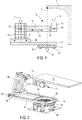
- a particle generator 1 is provided to generate radiation along a vertical axis 2 downwards.
- the positioning robot comprises a base 3 on which can rotate a linear rail 4 according to a vertical axis of rotation 5.
- this vertical axis of rotation 5 may be coincident with the axis 2 of the radiation.
- the positioning robot also comprises a junction piece 6a fixed on a base 6b pivotally along a vertical axis of rotation 7.
- the base 6b can move linearly, by translation, on the linear rail 4 along a horizontal translation axis 8.
- the junction piece 6a carries a robotic arm 9 composed of a forearm 10 and a wrist 11.
- the forearm 10 is fixed to the junction piece 6a pivotally about a horizontal axis of rotation 12.
- the forearm 10 is of sliding type so that it can lengthen linearly along a linear axis 13.
- the end of the forearm 10 furthest away from the connecting piece 6a carries the wrist 11 at three degrees of freedom along three orthogonal axes of rotation 14, 15 and 16 and concurrent.
- This wrist 11 is fixed on the sliding part of the forearm 10.
- the support table (not shown), intended to accommodate the patient, is generally fixed to the horizontal on the wrist 11.
- the positioning robot according to the invention is connected to a processing unit (not shown) able to manage the joints of this positioning robot in order to place the tumor of a patient at a predetermined position.
- This processing unit recovers in real time the articular positions of each of the axes thanks to encoders fixed to the motors. Then from the geometric parameters theoretical from the calibration of the robot, the processing unit is able to provide the user a Cartesian position of the tumor marker with respect to the virtual benchmark treatment. Thus, the user can easily interpret this position and verify that it complies with the requirement.
- the user can validate a correction to be applied to the tumor mark in the treatment mark according to the proposal of the system used for the registration of the patient (scanner, X-ray, infrared). Then, this order is analyzed and transcribed in joint control to the robot.
- the invention is furthermore provided with an advanced 3D visualization software, based on a theoretical model of the scene and the information retrieved by the various sensors present.
- This fine modeling of the positioning procedure makes it possible to consider eventually deporting orders outside the treatment room. This offset will advantageously move the positioner remotely and thus reduce the time lost by the operator to enter the room to change the incidence of treatment of the patient.
- the base 3 is constituted by a ring 3a, pivoting portion, mounted on studs 3b in aluminum profile firmly fixed to the ground.
- the linear rail 4 is a frame formed by two straight rails, pads with bearings 4a and 4b parallel, preferably steel section section "U". These two rails 4a and 4b are interconnected by three rails 4c, 4d and 4e parallel to each other and perpendicular to the two rails 4a and 4b.
- the rail 4c is disposed at one end of the linear rail assembly.
- the two rails 4c and 4d and part of the two rails 4a and 4b form a frame firmly attached to the crown 3a pivotally.
- the assembly of the linear rail 4 can rotate 360 ° along the vertical axis of rotation 5 passing through the center of the ring 3a.
- the base 6b is slidably engaged with the two rails 4a and 4b. This base 6b pivotally carries along the vertical axis of rotation 7 the junction piece 6a which is a metal frame held vertically.
- the robotic arm 9 is an arm according to the "SERIE" architecture. It is attached to an upper part of the connecting piece 6a and can pivot about the horizontal axis of rotation 12.
- the forearm 10 is an elongated and flared tube of the connection with the connecting piece 6a.
- the free end of the forearm carries the wrist 11 on which is fixed the support table 17 for the patient. This table 17 is kept substantially horizontal most of the time but it is brought to be positioned by the wrist.
- the table 17 may be a tray or chair in some cases for patient transport. It is carbon honeycomb-based to be transparent radio and very rigid while keeping a limited weight.
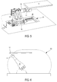
- the positioning robot is constituted such that it is compact in the rest position.
- a rest position may be the position shown on the figures 2 and 3 wherein the linear rail 4 and the forearm 10 are substantially parallel in the same vertical plane.
- the connecting piece is disposed on one end of the linear rail 4 opposite the base 3.
- the forearm 10 is fixed to the connecting piece 6a and is directed towards the base 3 while remaining parallel to the linear rail 4
- the table 17 is held above the wrist 11, one end fixed to the wrist 11, the other free end being directed away from the forearm.
- the figure 4 is a schematic view of the working space E1 for a positioning robot according to the invention.
- This space E1 is a volume of semi-spherical shape flattened on the top. The patient can thus be positioned continuously throughout the volume of this workspace E1.
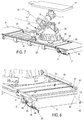
- junction piece 18 has been modified so that in this embodiment it is possible to install a high precision and high weight junction piece.
- the linear rail 21 is fixed to the ground and can easily receive a connecting piece 18 which can rotate 360 ° along an axis of vertical rotation relative to a base 19.
- This base 19 slides linearly along an axis horizontal translation on two linear rails 20 parallel and fixed to the ground.
- a small pit 21 in which are installed the first linear rail 20 and the second rail (not visible on the figure 5 ).
- This positioning robot thus has a horizontal translation axis on the linear rail and five axes of rotation: rotation of the connecting piece 18 relative to the base 19, the forearm 10 relative to the connecting piece, and the three axes of rotation of the wrist 11. It is also possible to add another translation axis because the forearm 10 can be slidable.
- the positioning robot is deployed.
- the robotic arm is in an oblique raised position.
- the wrist 11 holds the table 17 in a horizontal position.
- the working space E2 is a volume in the form of a half-sphere laterally elongate and flattened on the top.
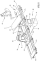
- FIG. 7 On the figure 7 is shown another advantageous embodiment of the robot according to the invention.
- a base 22 which is able to slide on two parallel linear rails 23 and 24 arranged laterally with respect to this base 22.
- a first motor 25 participates in the linear displacement of the base 22.
- a connecting piece 26, placed above of the base 22, is connected to this base 22 pivotally along a vertical axis.
- the connecting piece has a triangular shape with the base resting on the base 22 and an inclined blank receiving the robotic arm 9.
- a second motor 27 participates in the rotation of the connecting piece 26 relative to the base 22.
- the robotic arm 9 is connected to the connecting piece 26 pivotally about an axis of rotation 28 which is inclined at an angle ⁇ non-zero with respect to the horizontal.
- This angle ⁇ is preferably between 45 and 60 °. In this case, it is 60 °.
- This inclined arrangement allows the robot according to the invention to move in a reduced space such as a conventional hospital room with a ceiling limited to 2.5 meters for example, and at the same time to reach a minimum height of loading of patient of the order of 60cm, especially for the rise of a child or a senior on the plate 17.
- the inclined arrangement allows to place the robotic arm 9 and the connecting piece 26 on the base 22 the most possible near the ground without the rear portion 29 of the robotic arm 9 collides with obstacles, such as the base itself, during rotational movements. Indeed, in the preceding embodiments, the robotic arm 9 is attached to the connecting piece at a height sufficient for the rotation of the robotic arm does not intercept the base 6b for example on the figure 3 .
- the robot thus described has six axes of maneuverability, a translation and five rotations, or six degrees of freedom. We can place a patient in the workspace in any configuration.
- a floor consisting of two half-floors 30 and 31 is seen.
- the half-floor 30 is composed of several blades 32 interconnected in chains by means of articulations (visible on the figure 8 in 33).
- the half floor 30 is in the unfolded position, that is to say it is a solid flat floor on which the user can stand.
- This half-floor 30 slides in being integral with the base 22.
- the base 22 moves away from a left fixed floor 34
- the half floor 30 slides covering the pit which is between the left fixed floor 34 and the motor 25 fixed to the base 22.
- the half floor 30 slides to be placed in the folded position, in accordion, under the left fixed floor 34.
- the half floor 35 acts in the same way as the half floor 30 but in phase opposition. When one is folded, the other is unfolded, and vice versa.
- the half-floor 35 is in folded position under the right fixed floor 36. It can be seen that the blades 37 constituting the half-floor 35 are placed in accordion under the right fixed floor 36.
- Each secondary rail 38, 39 has a high linear portion 40 (not shown for the secondary rail 38) on which the blades 37 are in the unfolded position allowing the user to walk on it; a bending point 41, 42 in the shape of "S" and a linear low part 48, 43 parallel to the high linear part 40 but disposed substantially at the bottom of the pit.
- a second set of external secondary rails 44 and 45 have a spacing greater than that of the two internal secondary rails 38, 39.
- the two outer secondary rails remain linear throughout the movement of the blades 37. These blades bear at the level of the joints of the bearings arranged in staggered rows.
- Half of the bearings 46 is guided by the two internal secondary rails 38, 39, while the other half 47 is guided by the two external secondary rails 44 and 45, see figure 8 . More specifically, these bearings are alternately arranged, a bearing 46 is followed by a bearing 47 and vice versa.
- the bearings 47 slide in the external secondary rails 44 and 45, while the bearings 46 slide in the bending point 41, 42 which constitutes an access ramp to a lower level where the linear low part is located. 43, 48.
- the blades 37 are arranged vertically and accordion. They occupy a minimum volume and remain camouflaged. The blades 37 go from the horizontal state to the vertical state just with the effect of gravity, they are stored automatically and without additional motorization.
- the positioning device may be as previously described.
- the positioning device of the figure 9 comprising a junction piece 50 sliding on a linear rail 56 and carrying a robotic arm 53 having a wrist 54 with concurrent axes of rotation.
- the linear rail 56 is advantageously fixed to the ground and consists of several modular elements 57a, ..., 57d connected to each other. These modular elements can be identical so that their implementation in the treatment room is facilitated. With such an arrangement, it is thus easy to produce linear rails of different lengths.
- each modular element 57a, ..., 57d comprises a metal plate (or other solid material such as wood, plastic, ...) upper 67a, 67b, 67c placed on three uprights securely fixed to the floor, two side pillars 57h, 57i, and a central pillar 57g.
- Each upper metal plate has two grooves or lateral openings 58 and 59 on the figure 9 which are parallel and subdivide each upper metal plate into three parts 67a, 67b, 67c. These grooves give access to a confinement volume between the upper metal plates 67b and the ground.
- This containment volume contains a motor 66 on the figure 10 intended to slide the base 52 of the connecting piece 50 relative to the linear rail 56. More specifically, the base 52 is carried by pads 68 and 69. These pads comprise an upper part to support the base 52, a lower portion sliding on fixed rails 70 in the confinement volume, and a central portion shaped sufficiently narrow and solid to connect the upper part and the lower part via the grooves 58 and 59 without ever touching them.
- Such an embodiment makes it possible to camouflage the motor in an invisible confinement volume from the outside, this saves space and makes the top surface of the linear rail flat.
- the user can move safely on this floor consisting of the upper metal plates of the modular elements 57a, ..., 57d.
- the base 52 is associated with a pivot piece 51 pivotable about a vertical axis of rotation.
- the robotic arm 53 is pivotally connected to an upper portion of the junction piece 50 along an axis of rotation at an angle of between 45 and 60 degrees to the horizontal.
- the wrist 54 carries a patient support 71 which can be positioned very precisely in the repository of the treatment room.
- a processing unit 60 can electromechanically control the positioning device or robot.
- Several motors whose motor 66 for moving the linear rail are arranged on and in the robot so as to control any articulation of the robot automatically.
- a set of conventional sensors are arranged on the robot such as for example an inclinometer 65 disposed on the wrist 54. From the sensors as well as including the engines, the processing unit retrieves a set of information to know exactly in time real robot positioning. That is to say that at every moment we know the position of the support in the room and the value of the angles of inclination of the various elements of the robot.
- the processing unit includes a computer-like hardware portion with conventional elements for acquisition, analog and digital data processing.
- a hard disk 61 houses a 3D visualization module which then determines and displays on a screen 62 a 3D representation of the movement of the robot relative to the environment which is the treatment room.
- This visualization module thus comprises a virtual 3D modeling of the environment and a real-time virtual 3D modeling of the robot moving in the environment.
- it also comprises a virtual 3D modeling of a virtual envelope around the support 71 of the robot as well as a real-time collision detection algorithm between the virtual envelope and the modeled environment.
- the modeling of the environment takes into account the dimensions of the treatment room but also the elements or obstacles present in this treatment room.
- the treatment unit itself is distinguished as well as a radiation device 64 which is generally mobile.
- the processing unit is connected to the robot and the radiation device 64 wired 63 or wireless, so that the 3D viewing module can represent any mobile device in the treatment room.
- the modelizations are obtained from data acquired in real time and predetermined data. These predetermined data may correspond to the positioning data of the moving elements. These positions, like that of the processing unit, are known in advance and can be entered by the user.
- the virtual representation of the dynamics in the treatment room makes it possible to set up surveillance systems such as an anticollision process.
- figure 11 is a virtual 3D representation visible on the screen 62. Only the support 71 is shown for reasons of simplification.
- the virtual envelope 72 is of the same shape as the virtual representation of the support 71 but of greater dimensions. Consequently, when the support 71 is in motion, the envelope 72 follows the same movement and any probable collision of the support 71 with one of the elements of the treatment room is preceded by a virtual collision of the envelope 72 in the module. 3D visualization. In fact, the 3D representation makes it possible to alert the user of the real collision risk of the support 71 when the virtual envelope 72 collides with one another.
- the envelope 72 includes the 3D representation of the support 71, but this envelope 72 may be of different shape from that of the support and of smaller size, in particular to monitor only part of the support.
- 3D modeling of a virtual envelope can also be used on any mobile element of the treatment room. It is thus possible to provide a second virtual envelope around the radiation device 64, the collision being estimated between the two virtual envelopes.
- An anti-collision system makes it possible to increase the capacity of the use of a mobile system in space.
- a medical robot for example, is easily manoeuvrable by the operator safely without the need to worry about a possible contact.
- the machines are therefore more autonomous, they themselves ensure their own safety and that of those around them.
- the applied force generally comes from a user who manually moves the robot by for example pushing the patient support with his hands.
- the process of co-manipulation can be a process independent or associated with the collision avoidance technique with virtual envelope.
- the processing unit implements at the same time the collision detection.
- the sensor 65a may be a force sensor used to detect any force applied to the wrist 54.
- This type of force sensor may consist of several strain gages.
- the anticollision process allows a slow sliding of the support in the volume of the virtual envelope. This principle allows in co-manipulation mode to avoid untimely stops of the robot and to smooth the trajectories in the vicinity of elements present in the treatment room. Sliding is also an aid to the manipulation and manual guidance of the robot.
Description
La présente invention se rapporte à un dispositif de positionnement d'un patient par rapport à un faisceau de radiothérapie externe. Elle trouve une application particulièrement avantageuse dans le domaine de la radiothérapie où l'on utilise des faisceaux d'irradiation pour des traitements nécessitant une très grande précision par exemple pour le mélanome de la choroïde ou pour certaines tumeurs intracrâniennes. Lorsqu'une tumeur est notamment localisée à la base du crâne d'un patient, la radiothérapie a pour objet d'irradier les zones malignes tout en évitant de toucher des organes critiques, comme les nerfs optiques, le tronc cérébral, l'oreille interne ou la moelle épinière qui se trouvent proches. Il est donc primordial de positionner correctement le patient par rapport au rayonnement destiné à irradier une tumeur. D'une façon générale, en radiothérapie, le patient est installé sur une table ou une chaise puis positionné à l'aide d'un appareillage électromécanique.The present invention relates to a device for positioning a patient with respect to an external beam of radiotherapy. It finds a particularly advantageous application in the field of radiotherapy where irradiation beams are used for treatments requiring very high precision for example for choroidal melanoma or for certain intracranial tumors. When a tumor is located at the base of a patient's skull, radiotherapy aims to irradiate the malignant areas while avoiding touching critical organs, such as the optic nerves, the brainstem, the inner ear or the spinal cord that are close. It is therefore essential to correctly position the patient in relation to the radiation intended to irradiate a tumor. In general, in radiotherapy, the patient is installed on a table or a chair and then positioned using an electromechanical apparatus.
Toutefois, la présente invention est d'un cadre plus large puisqu'elle peut s'appliquer à d'autres domaines nécessitant de positionner avec précision un patient ou tout autre objet. La présente invention peut par exemple s'appliquer à des applications médicales de tout ordre, nécessitant la mise en place précise et rapide d'un patient par rapport à un référentiel donné.However, the present invention is of a broader scope since it can be applied to other areas requiring precise positioning of a patient or other object. The present invention may for example apply to medical applications of any order, requiring the precise and rapid implementation of a patient with respect to a given reference.
Dans l'art antérieur, le document
Par ailleurs, le document
Le document
La présente invention a pour but de remédier aux inconvénients de l'art antérieur en proposant un nouveau dispositif de positionnement compact et très rigide, possédant intrinsèquement une grande précision et évitant le recours à une fosse profonde.The present invention aims to overcome the disadvantages of the prior art by proposing a new compact positioning device and very rigid, intrinsically high accuracy and avoiding the use of a deep pit.
L'invention a pour objet de développer un robot de positionnement simple d'installation.The object of the invention is to develop a simple positioning robot for installation.
Enfin, l'invention a pour but de proposer un contrôle performant du robot de positionnement afin de garantir au mieux la sécurité du patient et du personnel de soins durant les déplacements.Finally, the invention aims to provide an effective control of the positioning robot to best ensure the safety of the patient and care staff during travel.
On atteint au moins l'un des buts précités avec un dispositif selon la revendication 1.At least one of the aforementioned objects is achieved with a device according to
L'invention constitue avantageusement un robot de positionnement très compact, mais capable d'évoluer avec une très grande précision dans un espace étendu. L'encombrement est très réduit par rapport aux dispositifs de l'art antérieur. En effet, la géométrie décrite diffère des morphologies habituelles par l'ordre et les angles utilisés pour l'agencement des segments mécaniques constituant le robot. Les concepts « scara », poly articulés ou hexapodes, présentés précédemment, ont l'inconvénient majeur de nécessiter une fosse profonde dans le sol.The invention advantageously constitutes a very compact positioning robot, but able to evolve with great precision in an extended space. The size is very small compared to the devices of the prior art. Indeed, the geometry described differs from the usual morphologies by the order and the angles used for the arrangement of the mechanical segments constituting the robot. The concepts "scara", poly articulated or hexapods, presented above, have the major disadvantage of requiring a deep pit in the ground.
En outre, la présente invention est innovante en termes d'encombrement et de compacité en position de repli dans la salle. Pour rendre l'espace de travail d'un tel système, optimal, il doit être centré sur un plan dont l'altitude par rapport au sol peut varier de un mètre vingt à un mètre cinquante. Cette contrainte est inhérente au principe du traitement par faisceau de radiothérapie.In addition, the present invention is innovative in terms of size and compactness in the folded position in the room. To make the work space of such a system optimal, it must be centered on a plane whose altitude relative to the ground can vary from one meter twenty to one meter fifty. This constraint is inherent in the principle of radiotherapy beam therapy.
L'objet de la présente invention est d'autant plus remarquable qu'il constitue un robot de positionnement hybride, la liaison entre l'épaule et le coude de la morphologie poly articulée dite « série » (robot à mouvements de type bras humain) est avantageusement remplacée par le couplage de l'axe linéaire au sol et de la pièce de jonction sur pivot vertical précédemment décrite. Ces changements résolvent les deux contraintes de mobilité (axe de translation) et de compacité (pièce de jonction). Le robot est compact parce que le rail permet de déplacer l'ensemble du bras robotique (de la pièce de jonction jusqu'au support du patient) par translation jusqu'à l'emplacement prévu par le planning de traitement. Le bras robotique, avec ses multiples degrés de liberté, peut ensuite effectuer des mouvements à faible débattement mais nécessitant une grande précision pour optimiser la position de la cible à traiter dans le référentiel de traitement.The object of the present invention is all the more remarkable in that it constitutes a hybrid positioning robot, the connection between the shoulder and the elbow of the so-called "series" poly-articulated morphology (human-arm motion robot). is advantageously replaced by the coupling of the linear axis to the ground and the vertical pivot junction piece previously described. These changes solve the two constraints of mobility (axis of translation) and compactness (junction piece). The robot is compact because the rail moves the entire robotic arm (from the connecting piece to the patient's support) by translation to the location provided by the treatment schedule. The robotic arm, with its multiple degrees of freedom, can then make movements to low clearance but requiring high accuracy to optimize the position of the target to be processed in the processing repository.
Ce robot de positionnement compact à six degrés de liberté permet de limiter la profondeur de la fosse et est capable de transporter de fortes charges d'au moins 250kg avec l'encombrement d'une table de radiothérapie standard. Avec un tel rail linéaire selon l'invention, on peut prévoir un bras robotique court, d'environ 1m30. Ce robot de positionnement présente une raideur et une compacité accrue par rapport à un système de l'art antérieur dans la mesure où ce robot ne dispose pas d'axe déporté, loin de la base.This compact positioning robot with six degrees of freedom allows to limit the depth of the pit and is able to carry heavy loads of at least 250kg with the size of a standard radiotherapy table. With such a linear rail according to the invention, a short robotic arm of about 1m30 can be provided. This positioning robot has a stiffness and increased compactness compared to a system of the prior art insofar as this robot does not have a remote axis, far from the base.
L'invention, de part la compacité de sa morphologie, possède un centre de gravité assez proche de sa base pour limiter l'effet de porte à faux observé sur les dispositifs de l'art antérieur. Tout le poids du robot de positionnement est donc réparti au sol, ce qui améliore la stabilité et la rigidité du dispositif.The invention, because of the compactness of its morphology, has a center of gravity close enough to its base to limit the effect of overhang observed on the devices of the prior art. All the weight of the positioning robot is therefore distributed to the ground, which improves the stability and rigidity of the device.
Le robot de positionnement selon l'invention permet d'optimiser et d'adapter l'espace de travail à une application donnée. En effet, la taille du rail linéaire peut varier en fonction de l'espace disponible et des fonctionnalités optionnelles désirées. Il est ainsi envisagé d'augmenter la longueur de l'axe afin de réaliser un pré-positionnement du patient grâce à un imageur scanner d'un côté de la salle puis d'envoyer directement le patient en position de traitement sous l'appareil de radiothérapie par une translation pure de la base du robot. Cette fonctionnalité remplacerait avantageusement les procédures actuelles, fastidieuses et peu adaptées pour certains traitements en pédiatrie notamment.The positioning robot according to the invention makes it possible to optimize and adapt the work space to a given application. Indeed, the size of the linear rail may vary depending on the available space and desired optional features. It is thus envisaged to increase the length of the axis in order to perform a pre-positioning of the patient by means of a scanner imager on one side of the room and then to directly send the patient to the treatment position under the device of the patient. radiotherapy by a pure translation of the base of the robot. This functionality would advantageously replace the current, tedious and unsuitable procedures for certain pediatric treatments in particular.
Selon un autre mode d'assemblage des axes du robot, le rail linéaire peut être fixé à une partie pivotante d'une base, l'axe de pivot de cette partie pivotante étant vertical. Dans le cas d'un tel assemblage, on peut installer le système dans une fosse peu profonde (de l'ordre de 300mm maximum de profondeur). Par l'ajout de ce nouvel axe, le robot comporte sept axes combinant six rotations et une translation, pour une mobilité maximale de six degrés de liberté. Cet ajout rend l'architecture redondante et permet d'atteindre des positions difficiles d'accès dans un milieu encombré comme une salle de traitement.According to another method of assembling the axes of the robot, the linear rail can be fixed to a pivoting part of a base, the pivot axis of this pivoting part being vertical. In the case of such an assembly, one can install the system in a shallow pit (about 300mm maximum depth). By adding this new axis, the robot has seven axes combining six rotations and a translation, for a maximum mobility of six degrees of freedom. This addition renders the architecture redundant and makes it possible to reach positions that are difficult to access in a congested environment such as a treatment room.
Pratiquement, pour assurer une bonne précision, on prévoit que la partie pivotante pivote par rapport à une partie fixe de la base au moyen d'un roulement à billes. La partie fixe de la base peut comprendre plusieurs plots en profilé aluminium fixés au sol dans une petite fosse par exemple. L'assemblage ainsi réalisé permet de réaliser une rotation de l'ensemble rail linéaire plus bras robotique de 360°. L'enveloppe de travail d'un tel appareillage correspond à une demi-sphère, sans zone morte.Practically, to ensure good accuracy, it is expected that the pivoting portion pivots relative to a fixed portion of the base by means of a ball bearing. The fixed part of the base may include several studs aluminum profile fixed to the ground in a small pit for example. The assembly thus produced allows a rotation of the linear rail assembly plus robotic arm of 360 °. The working envelope of such apparatus corresponds to a half-sphere, without dead zone.
De préférence, l'axe de rotation vertical du rail linéaire par rapport à la base est confondu avec l'axe ou l'aplomb dudit faisceau de rayonnement. Ainsi, lorsqu'une cible, par exemple dans la tête d'un patient, est convenablement positionnée par rapport au rayonnement, il suffit d'une rotation pure de l'axe au sol, pour faire tourner le patient, changer l'angle d'incidence du rayonnement, tout en gardant la cible dans l'axe. Ceci permet d'envisager un traitement dynamique du patient en combinant le déplacement du robot avec la forme du collimateur multi lames de mise en forme du faisceau.Preferably, the vertical axis of rotation of the linear rail relative to the base coincides with the axis or the plumb with said beam of radiation. Thus, when a target, for example in the head of a patient, is properly positioned relative to the radiation, it is sufficient to rotate the axis on the ground, to rotate the patient, to change the angle of the patient. incidence of radiation, while keeping the target in the axis. This makes it possible to envisage a dynamic treatment of the patient by combining the movement of the robot with the shape of the multi-beam collimator beam shaping.
Avantageusement, le bras robotique comprend un avant bras coulissant. L'intérêt est d'avoir un volume de calibration lié au terminal du robot (dans lequel le robot est très précis) qui suit l'axe linéaire. Ce volume se déplace selon un axe très précis (précision axe linéaire <0.1mm) et l'on peut avoir un volume de précision suivant en permanence la zone à traiter. Le terminal, parfois appelé effecteur, correspond à l'extrémité du robot (dispositif de positionnement). Il s'agit généralement d'une plaque d'accroche entre le robot et le support de patient.Advantageously, the robotic arm comprises a sliding forearm. The interest is to have a calibration volume linked to the terminal of the robot (in which the robot is very precise) which follows the linear axis. This volume moves along a very precise axis (precision linear axis <0.1mm) and one can have a volume of precision following the zone to be treated permanently. The terminal, sometimes called effector, corresponds to the end of the robot (positioning device). This is usually a hook plate between the robot and the patient support.
Avec un rail linéaire selon l'invention, il est alors possible de simplifier la calibration du dispositif de positionnement. En effet, on peut réaliser un nombre de points de mesure limité, par exemple huit points aux coins d'un volume cubique. On calcule ensuite dans ce volume un certain nombre de positions cartésiennes maximisant des variations articulaires importantes pour chaque déplacement. Le robot aura une précision très élevée dans ce volume, lié à son terminal, qui se déplacera très précisément suivant l'axe linéaire.With a linear rail according to the invention, it is then possible to simplify the calibration of the positioning device. Indeed, it is possible to achieve a limited number of measurement points, for example eight points at the corners of a cubic volume. A number of Cartesian positions are then calculated in this volume, maximizing significant articular variations for each displacement. The robot will have a very high accuracy in this volume, linked to its terminal, which will move very precisely along the linear axis.
Le bras robotique peut être relié à la pièce de jonction de façon pivotante selon un axe de rotation horizontal.The robotic arm can be connected to the junction piece pivotally along a horizontal axis of rotation.
Selon une autre variante de l'invention, le bras robotique est relié à la pièce de jonction de façon pivotante selon un axe de rotation incliné par rapport à l'horizontal d'un angle compris entre 0° et 90°. De préférence, l'axe de rotation du bras robotique par rapport à la pièce de jonction est incliné par rapport à l'horizontal d'un angle compris entre 45 et 60 degrés. Cette inclinaison est notamment utile pour l'inversion du bras (passage du bras de l'avant du robot vers l'arrière) dans un espace confiné avec une hauteur sous plafond réduite.According to another variant of the invention, the robotic arm is pivotally connected to the connecting piece along an axis of rotation inclined relative to the horizontal by an angle of between 0 ° and 90 °. Preferably, the axis of rotation of the robotic arm relative to the junction piece is inclined relative to the horizontal by an angle of between 45 and 60 degrees. This inclination is particularly useful for the inversion of the arm (passage of the arm of the robot front to the rear) in a confined space with a reduced ceiling height.
Par ailleurs, la pièce de jonction peut être reliée de façon pivotante selon un axe vertical à une embase qui est reliée de façon coulissante audit au moins un rail linéaire.Furthermore, the connecting piece can be pivotally connected along a vertical axis to a base which is slidably connected to the at least one linear rail.
Le poignet est relié au support de patient au moyen d'un changeur d'outil électropneumatique standard.The wrist is connected to the patient support using a standard electro-pneumatic tool changer.
Selon une caractéristique avantageuse de l'invention, la pièce de jonction se déplace par roulement sur le rail linéaire conçu en profilé acier en « U ».According to an advantageous characteristic of the invention, the connecting piece is rotated on the linear rail designed in "U" steel profile.
Avantageusement, le dispositif selon l'invention est conçu de manière à limiter la manutention lors de l'installation dans la salle de traitement, grâce à l'ajout de roues amovibles ou escamotables qui supportent le dispositif lors d'une installation. Ces roues peuvent être fixées sur la base du châssis du dispositif. Ceci facilite la manutention du dispositif et permet un remplacement facile d'un positionneur dans une salle existante.Advantageously, the device according to the invention is designed to limit handling during installation in the treatment room, through the addition of removable or retractable wheels that support the device during installation. These wheels can be attached to the base of the device frame. This facilitates the handling of the device and allows easy replacement of a positioner in an existing room.
Selon une caractéristique avantageuse de l'invention, le dispositif comprend un plancher mobile constitué de deux demi-planchers reliés à la pièce de jonction et disposés de part et d'autre de cette pièce de jonction de façon à couvrir constamment le rail linéaire lorsque la pièce de jonction se déplace ; chaque demi-plancher est constitué de plusieurs lames reliées entre elles en chaîne par des articulations, de telle sorte qu'en position de repli d'un demi-plancher, au moins une partie des lames de ce demi-plancher est rangée en accordéon sous un plan horizontal qui contient ce demi-plancher en position dépliée.According to an advantageous characteristic of the invention, the device comprises a movable floor consisting of two half-floors connected to the connecting piece and arranged on either side of this connecting piece so as to constantly cover the linear rail when the junction piece moves; each half-floor consists of several blades interconnected in chain by hinges, so that in the folded position of a half-floor, at least a portion of the blades of this half-floor is arranged in an accordion under a horizontal plane which contains this half-floor in unfolded position.
De préférence, le plancher coulisse sur deux jeux de rails secondaires :
- un premier jeu de rails secondaires internes sur lesquels coulisse la moitié des articulations, ces deux rails secondaires internes étant parallèles et écartés l'un de l'autre ; ces deux rails secondaires internes présentant une partie linéaire haute, un point de flexion et une partie linéaire basse ;
- un second jeu constitué de deux rails secondaires externes sur lesquels coulisse l'autre moitié des articulations, ces deux rails secondaires externes étant parallèles et écartés d'une distance supérieure à la distance d'écartement des deux rails secondaires internes ; ces deux rails secondaires externes étant linéaires dans un plan horizontal sensiblement à la même hauteur que la partie linéaire haute des rails secondaires internes ;
- a first set of internal secondary rails on which slides half of the joints, these two internal secondary rails being parallel and spaced apart from each other; these two internal secondary rails having a high linear part, a bending point and a linear low part;
- a second set consisting of two external secondary rails on which slide the other half of the joints, these two outer secondary rails being parallel and spaced apart by a distance greater than the spacing distance of the two internal secondary rails; these two external secondary rails being linear in a horizontal plane substantially at the same height as the high linear part of the internal secondary rails;
Avantageusement, chaque demi-plancher présente en position dépliée une partie plate proche de la pièce de jonction, et en position de repli une partie repliée en accordéon entre la partie linéaire basse des rails secondaires internes et les rails secondaires externes.Advantageously, each half-floor has in the unfolded position a flat portion near the joining piece, and in folded position an accordion-folded portion between the low linear part of the internal secondary rails and the external secondary rails.
Selon une variante avantageuse de l'invention, le plancher est fixe. Dans ce cas, le rail linéaire est constitué par une pluralité d'éléments modulaires fixés au sol et connectés entre eux. Ces éléments modulaires peuvent présenter par exemple une longueur de 1m et permettent d'adapter la course du robot à une application donnée telle que la disposition d'un scanner d'un côté de la salle et d'un accélérateur de traitement d'un autre côté.According to an advantageous variant of the invention, the floor is fixed. In this case, the linear rail is constituted by a plurality of modular elements fixed to the ground and connected to each other. These modular elements may have, for example, a length of 1m and make it possible to adapt the stroke of the robot to a given application such as the arrangement of a scanner on one side of the room and a treatment accelerator of another. side.
Selon un autre aspect de l'invention, il est proposé un système de positionnement comprenant un dispositif de positionnement tel que défini précédemment, une unité de traitement intégrant un logiciel de supervision, une série de capteurs de recalage du patient et notamment une série de capteurs de sécurité.According to another aspect of the invention, there is provided a positioning system comprising a positioning device as defined above, a processing unit integrating a supervision software, a series of sensors for resetting the patient and in particular a series of sensors. of security.
La vérification des déplacements est assurée par la mise en place de capteurs et logiciel. Les capteurs utilisés sont pour partie des capteurs évolués tels qu'un capteur stéréovision infrarouge capable de suivre le déplacement de cibles à géométrie connue, des capteurs rayons X, des caméras industrielles et un capteur d'effort sur l'organe terminal du robot. L'ensemble des informations recueillies par ces capteurs convergent vers un même centre de traitement, appelé superviseur. Le superviseur connaît l'état courant de l'environnement du robot et peut le comparer avec la configuration théorique de la salle pour la tâche demandée. Cette comparaison s'accompagne d'une modification éventuelle de la trajectoire en cas d'évitement d'obstacles, d'une diminution de la vitesse à l'approche d'une zone potentiellement dangereuse ou d'un avertissement à l'opérateur en cas de problème. Chaque changement par rapport au scénario original étant signalé à l'opérateur dans l'interface de supervision. La sécurité est renforcée par l'ajout d'une couche de capteurs bas niveau : résolveurs, accéléromètres, compteurs impulsionnels sur chaque axe, inclinomètres, bandes anti collisions, ayant pour fonction de couper la puissance du robot en cas de dépassement des limites imposées par les normes régissant l'installation des systèmes électromécaniques en milieu médical.
Selon l'invention, l'unité de traitement peut comprendre un module de visualisation 3D doté :
- d'une modélisation 3D virtuelle de la salle de traitement où se situe le dispositif de positionnement ;
- d'une modélisation 3D virtuelle du dispositif de positionnement ; cette modélisation étant paramétrée pour représenter le positionnement temps réel du dispositif de positionnement à partir de capteurs, et pour définir une enveloppe virtuelle autour au moins d'un élément du dispositif de positionnement de façon à générer un signal d'alerte lorsque l'enveloppe virtuelle entre en collision avec une représentation virtuelle d'un élément de la salle de traitement.
According to the invention, the processing unit can comprise a 3D visualization module provided with:
- virtual 3D modeling of the treatment room where the positioning device is located;
- virtual 3D modeling of the positioning device; this modeling being parameterized to represent the real-time positioning of the positioning device from sensors, and to define a virtual envelope around at least one element of the positioning device so as to generate an alert signal when the virtual envelope collides with a virtual representation of an element of the treatment room.
L'unité de traitement peut être paramétrée de façon à déclencher, en réponse au signal d'alerte, un processus anticollision consistant à arrêter le dispositif de positionnement ou à réorienter le mouvement du dispositif de positionnement.The processing unit can be set to trigger, in response to the alert signal, an anti-collision process of stopping the positioning device or reorienting the movement of the positioning device.
Avec le système selon l'invention, une commande déportée du robot de positionnement améliore la sécurité des déplacements grâce à l'optimisation des trajectoires choisies et à l'interprétation facilitée des ordres à envoyer. Le module de visualisation 3D est notamment utile pour le rendu visuel de la scène et de l'évolution du robot. A partir des mesures des capteurs (position du robot) et de la simulation précise de chaque partie du système (accessoire de traitement, table ou chaise), on peut anticiper et éviter les collisions. Cette fonctionnalité est avantageusement basée sur des enveloppes virtuelles autour de chacun des éléments (fixes ou mobiles) présents dans la salle de traitement. Ce mode de réalisation constitue un système anticollision permettant le déplacement du robot dans la salle de traitement sans risque de collision.With the system according to the invention, a remote control of the positioning robot improves the safety of the displacements thanks to the optimization of the chosen trajectories and to the facilitated interpretation of the orders to be sent. The 3D visualization module is particularly useful for visual rendering of the scene and the evolution of the robot. From sensor measurements (robot position) and precise simulation of each part of the system (accessory treatment, table or chair), we can anticipate and avoid collisions. This feature is advantageously based on virtual envelopes around each of the elements (fixed or mobile) present in the treatment room. This embodiment is an anti-collision system for moving the robot in the treatment room without risk of collision.
Selon une autre caractéristique avantageuse, le dispositif selon l'invention comprend au moins un capteur d'effort fixé au poignet, de préférence au terminal du dispositif de positionnement, et relié à une unité de traitement contrôlant ledit dispositif de positionnement de façon à réaliser une co-manipulation en accompagnant tout effort détecté par ledit au moins un capteur d'effort. Plus précisément, le capteur d'effort peut comprendre six jauges de contraintes. Les efforts détectés sont transmis à l'unité de traitement (un ordinateur par exemple) qui les traite et renvoie au robot la commande de déplacement dans le sens de l'effort. Cette boucle de commande permet à un utilisateur de manipuler l'outil sans aucune contrainte de masse. Les inerties, et le poids sont compensés par le robot. Les possibilités de mouvements sont celles du robot, c'est-à-dire les six degrés de liberté, trois translations et trois rotations. Ce mode de réalisation permet une manipulation manuelle du robot. L'objectif est notamment de déplacer un patient posé sur le support en co-manipulation pour l'aligner intuitivement devant un appareil d'imagerie ou de traitement à l'aide de systèmes lasers standards. Cette opération de placement à la main du patient permet de diminuer les temps de mise en position. Il s'agit d'un pré-positionnement qui peut aussi être avantageusement utilisé pour une extraction d'urgence intuitive du patient en cas de malaise. Cette méthode est intuitive car l'effort qu'un utilisateur exerce sur le robot est relayé par un déplacement sous asservissement du dispositif de positionnement qui commande un système électromécanique.According to another advantageous characteristic, the device according to the invention comprises at least one force sensor fixed to the wrist, preferably to the terminal of the positioning device, and connected to a processing unit controlling said positioning device so as to realize a co-manipulation accompanying any effort detected by said at least one force sensor. More precisely, the force sensor may comprise six strain gages. The detected efforts are transmitted to the processing unit (a computer for example) which processes them and sends back to the robot the movement control in the direction of the effort. This control loop allows a user to manipulate the tool without any mass constraints. The inertia, and the weight are compensated by the robot. The possibilities of movements are those of the robot, that is to say the six degrees of freedom, three translations and three rotations. This embodiment allows manual manipulation of the robot. The goal is to move a patient on the support co-manipulation to align intuitively in front of an imaging device or treatment using standard laser systems. This operation of placing the patient's hand allows to reduce the setting time. This is a pre-positioning which can also be advantageously used for an intuitive emergency extraction of the patient in case of discomfort. This method is intuitive because the effort that a user exerts on the robot is relayed by a servocontrolled displacement of the positioning device which controls an electromechanical system.
Le capteur d'effort peut également être utilisé comme mesure de charge embarquée. Cette mesure est utilisée pour régler les paramètres d'asservissement à la co-manipulation, mais également pour avoir une idée des déformations subies par le robot et ainsi les compenser. Cette mesure directe du capteur est automatisée et par conséquence complètement transparente pour l'utilisateur.The force sensor can also be used as an onboard load measurement. This measurement is used to adjust the servocontrol parameters to the co-manipulation, but also to have an idea of the deformations undergone by the robot and thus to compensate them. This direct measurement of the sensor is automated and therefore completely transparent to the user.
Le capteur d'effort peut encore être utilisé pour la détection de collisions avec des objets mobiles. Lors d'un déplacement du robot suivant une trajectoire prédéfinie ou dynamique, ou pour toute autre manipulation, l'outil peut rentrer en collision avec d'autres éléments de l'environnement (humain, chariot, ...). Ces collisions engendrent des efforts inattendus sur le capteur, on peut donc mettre le robot en arrêt d'urgence pour éviter d'endommager l'une ou l'autre des parties en collision.The force sensor can still be used for the detection of collisions with moving objects. When moving the robot along a predefined or dynamic path, or for any other manipulation, the tool may collide with other elements of the environment (human, carriage, ...). These collisions cause unexpected forces on the sensor, so you can put the robot into emergency stop to avoid damaging one or the other of the colliding parts.
D'autres avantages et caractéristiques de l'invention apparaîtront à l'examen de la description détaillée d'un mode de mise en oeuvre nullement limitatif, et des dessins annexés, sur lesquels :
-
Figure 1 est une vue schématique illustrant le principe cinématique d'un robot de positionnement selon l'invention, -
Figure 2 est une première vue schématique latérale du dispositif de positionnement selon l'invention, -
Figure 3 est une seconde vue schématique latérale du dispositif de positionnement selon l'invention, -
Figure 4 est une vue schématique illustrant un espace de travail dans lequel le robot de positionnement selon l'invention peut se mouvoir, -
Figure 5 est une vue schématique d'un robot de positionnement selon l'invention pour lequel le rail linéaire est fixé au sol, -
Figure 6 est une vue schématique du robot de positionnement selon l'invention dans une position déployée, -
Figures 7 sont des vues schématiques illustrant un mode de réalisation dans lequel le plancher sur le rail linéaire est mobile,et 8 -
Figure 9 est une vue schématique d'un mode de réalisation où le plancher est fixe et composé d'éléments modulaires ; -
Figure 10 est une vue schématique de côté du robot de positionnement de lafigure 9 sans le support de patient ; et -
Figure 11 est une représentation virtuelle d'un support de patient du robot de positionnement de lafigure 9 .
-
Figure 1 is a schematic view illustrating the kinematic principle of a positioning robot according to the invention, -
Figure 2 is a first schematic side view of the positioning device according to the invention, -
Figure 3 is a second schematic side view of the positioning device according to the invention, -
Figure 4 is a schematic view illustrating a work space in which the positioning robot according to the invention can move, -
Figure 5 is a schematic view of a positioning robot according to the invention for which the linear rail is fixed to the ground, -
Figure 6 is a schematic view of the positioning robot according to the invention in an extended position, -
Figures 7 and 8 are schematic views illustrating an embodiment in which the floor on the linear rail is movable, -
Figure 9 is a schematic view of an embodiment where the floor is fixed and composed of modular elements; -
Figure 10 is a schematic side view of the positioning robot of thefigure 9 without the patient support; and -
Figure 11 is a virtual representation of a patient support of the positioning robot of thefigure 9 .
Un robot de positionnement selon l'invention est généralement destiné à positionner un patient par rapport à un rayonnement ionisant lors d'une radiothérapie externe. Un tel robot de positionnement est disposé dans une salle dimensionnée pour de tels traitements thérapeutiques. Cette salle est équipée d'un accélérateur de particules qui est apte à générer un rayonnement focalisé sur la tumeur à traiter dans le corps du patient. On comprendra aisément que le positionnement du patient doit être le plus précis possible et stable tout au long du traitement.A positioning robot according to the invention is generally intended to position a patient with respect to ionizing radiation during external radiotherapy. Such a positioning robot is arranged in a room sized for such therapeutic treatments. This room is equipped with a particle accelerator that is able to generate a radiation focused on the tumor to be treated in the patient's body. It will be readily understood that the positioning of the patient must be as precise as possible and stable throughout the treatment.
Un robot de positionnement est un bras articulé qui porte une table support ou une chaise support ou tout autre moyen de support sur lequel un patient se place. Les articulations du robot de positionnement sont commandées par une unité de traitement et sont aptes à positionner la tumeur du patient en tout point à l'intérieur d'un espace de travail tridimensionnel.A positioning robot is an articulated arm that carries a support table or a support chair or any other support means on which a patient places himself. The articulations of the positioning robot are controlled by a treatment unit and are able to position the patient's tumor at any point within a three-dimensional work space.
Sur la
Le robot de positionnement comporte une base 3 sur laquelle peut pivoter un rail linéaire 4 selon un axe de rotation vertical 5. Avantageusement, cet axe de rotation vertical 5 peut être confondu avec l'axe 2 du rayonnement. Le robot de positionnement comporte également une pièce de jonction 6a fixée sur une embase 6b de façon pivotante selon un axe de rotation 7 vertical. L'embase 6b peut se déplacer linéairement, par translation, sur le rail linéaire 4 selon un axe de translation 8 horizontal. La pièce de jonction 6a porte un bras robotique 9 composé d'un avant bras 10 et d'un poignet 11. L'avant bras 10 est fixé à la pièce de jonction 6a de façon pivotante selon un axe de rotation 12 horizontal. De préférence, l'avant bras 10 est de type coulissant de sorte qu'il peut s'allonger linéairement selon un axe linéaire 13. L'extrémité de l'avant bras 10 la plus éloignée de la pièce de jonction 6a porte le poignet 11 à trois degrés de liberté selon trois axes de rotation orthogonaux 14, 15 et 16 et concourants. Ce poignet 11 est fixé sur la partie coulissante de l'avant bras 10. La table support (non représentée), destinée à accueillir le patient, se fixe généralement à l'horizontal sur le poignet 11.The positioning robot comprises a
De façon conventionnelle, le robot de positionnement selon l'invention est relié à une unité de traitement (non représentée) apte à gérer les articulations de ce robot de positionnement afin de placer la tumeur d'un patient à une position prédéterminée. Cette unité de traitement récupère en temps réel les positions articulaires de chacun des axes grâce à des encodeurs fixés aux moteurs. Ensuite, à partir des paramètres géométriques théoriques issus de la calibration du robot, l'unité de traitement est en mesure de fournir à l'utilisateur une position cartésienne du repère de la tumeur par rapport au repère virtuel de traitement. Ainsi, l'utilisateur peut aisément interpréter cette position et vérifier qu'elle est conforme à la prescription. De la même manière, l'utilisateur peut valider une correction à appliquer au repère de la tumeur dans le repère de traitement conformément à la proposition du système utilisé pour le recalage du patient (scanner, rayons X, infrarouge). Ensuite, cet ordre est analysé et retranscrit en commande articulaire au robot.Conventionally, the positioning robot according to the invention is connected to a processing unit (not shown) able to manage the joints of this positioning robot in order to place the tumor of a patient at a predetermined position. This processing unit recovers in real time the articular positions of each of the axes thanks to encoders fixed to the motors. Then from the geometric parameters theoretical from the calibration of the robot, the processing unit is able to provide the user a Cartesian position of the tumor marker with respect to the virtual benchmark treatment. Thus, the user can easily interpret this position and verify that it complies with the requirement. In the same way, the user can validate a correction to be applied to the tumor mark in the treatment mark according to the proposal of the system used for the registration of the patient (scanner, X-ray, infrared). Then, this order is analyzed and transcribed in joint control to the robot.
L'invention se voit de plus doté d'un logiciel de visualisation 3D avancé, basé sur un modèle théorique de la scène et sur les informations récupérées par les différents capteurs en présence. Cette modélisation fine de la procédure de positionnement permet d'envisager à terme un déport des commandes en dehors de la salle de traitement. Ce déport permettra avantageusement de déplacer le positionneur à distance et ainsi de réduire le temps perdu, par l'opérateur, à rentrer dans la salle pour changer l'incidence de traitement du patient.The invention is furthermore provided with an advanced 3D visualization software, based on a theoretical model of the scene and the information retrieved by the various sensors present. This fine modeling of the positioning procedure makes it possible to consider eventually deporting orders outside the treatment room. This offset will advantageously move the positioner remotely and thus reduce the time lost by the operator to enter the room to change the incidence of treatment of the patient.
Sur les
Le rail linéaire 4 est un cadre formé par deux rails droits, de patins avec roulements 4a et 4b parallèles, de préférence en profilé acier de section en « U ». Ces deux rails 4a et 4b sont reliés entre eux par trois rails 4c, 4d et 4e parallèles entre eux et perpendiculaires avec les deux rails 4a et 4b. Le rail 4c est disposé à une extrémité de l'ensemble rail linéaire. Les deux rails 4c et 4d et une partie des deux rails 4a et 4b constituent un cadre solidement fixé à la couronne 3a de façon pivotante. L'ensemble du rail linéaire 4 peut pivoter en 360° selon l'axe de rotation vertical 5 passant au centre de la couronne 3a.The linear rail 4 is a frame formed by two straight rails, pads with
L'embase 6b est en prise de façon coulissante avec les deux rails 4a et 4b. Cette embase 6b porte de façon pivotante selon l'axe de rotation vertical 7 la pièce de jonction 6a qui est un cadre métallique maintenu verticalement. Le bras robotique 9 est un bras selon l'architecture « SERIE ». Il est fixé à une partie supérieure de la pièce de jonction 6a et peut pivoter selon l'axe de rotation horizontal 12. L'avant bras 10 est un tube allongé et évasé au niveau de la liaison avec la pièce de jonction 6a. L'extrémité libre de l'avant bras porte le poignet 11 sur lequel est fixée la table 17 support pour le patient. Cette table 17 est maintenue sensiblement à l'horizontal la plupart du temps mais elle est amenée à être positionnée par le poignet. La table 17 peut être un plateau ou une chaise dans certains cas pour le transport de patient. Elle est en carbone à base de nid d'abeille afin d'être radio transparente et très rigide tout en gardant un poids limité.The
Le robot de positionnement est constitué de telle sorte qu'il est compact en position de repos.The positioning robot is constituted such that it is compact in the rest position.
Par exemple, une position de repos peut être la position illustrée sur les
Pour améliorer sa compacité, on peut également prévoir un rail linéaire coulissant de sorte qu'en position de repli, l'encombrement soit minimum et/ou le centre de gravité du robot de positionnement soit le plus près possible de l'axe de rotation 5. Avec un rail coulissant, on augmente l'amplitude linéaire de travail, donc l'espace de travail.To improve its compactness, it is also possible to provide a sliding linear rail so that in the folded position, the space requirement is minimum and / or the center of gravity of the positioning robot is as close as possible to the axis of
La
Sur la
Avec un tel robot de positionnement, on peut garantir un positionnement précis de la tumeur à ± 0,5 mm et ± 0,5 degrés près, ainsi que des possibilités de grands déplacements :
- Delta X = ± 1000 mm (axe longitudinal en version nominale de l'axe linéaire)
- Delta Y = ± 1000 mm (axe latéral)
- Delta Z = ± 800 mm (axe vertical)
- Delta Rx = ± 20 deg (axe longitudinal)
- Delta Ry = ± 20 deg (axe latéral)
- Delta Rz = ± 110 deg (axe vertical)
- Delta X = ± 1000 mm (longitudinal axis in nominal version of the linear axis)
- Delta Y = ± 1000 mm (lateral axis)
- Delta Z = ± 800 mm (vertical axis)
- Delta Rx = ± 20 deg (longitudinal axis)
- Delta Ry = ± 20 deg (lateral axis)
- Delta Rz = ± 110 deg (vertical axis)
Sur la
Sur la
Le robot ainsi décrit possède six axes de manoeuvrabilité, une translation et cinq rotations, soit six degrés de liberté. On peut donc placer un patient dans l'espace de travail dans n'importe quelle configuration.The robot thus described has six axes of maneuverability, a translation and five rotations, or six degrees of freedom. We can place a patient in the workspace in any configuration.
Selon un autre aspect de l'invention représenté également sur la
Sur la
Un premier jeu de rails secondaires internes 38 et 39 (représenté en pointillé). Chaque rail secondaire 38, 39, comporte une partie linéaire haute 40 (non représentée pour le rail secondaire 38) sur laquelle se trouve les lames 37 en position dépliée permettant à l'utilisateur de marcher dessus ; un point de flexion 41, 42 en forme de « S » et une partie linéaire basse 48, 43 parallèle à la partie linéaire haute 40 mais disposée pratiquement au fond de la fosse.A first set of internal secondary rails 38 and 39 (shown in dashed line). Each
Un second jeu de rails secondaires externes 44 et 45 présentent un écartement supérieure à celui des deux rails secondaires internes 38, 39. Les deux rails secondaires externes restent linéaires tout le long du déplacement des lames 37. Ces lames portent au niveau des articulations des roulements disposés en quinconce. La moitié des roulements 46 est guidée par les deux rails secondaires internes 38, 39, alors que l'autre moitié 47 est guidée par les deux rails secondaires externes 44 et 45, voir
Sur la
Le dispositif de positionnement peut être tel que décrit précédemment. De préférence, on utilise le dispositif de positionnement de la
Le rail linéaire 56 est avantageusement fixés au sol et est constitué de plusieurs éléments modulaires 57a,..., 57d reliés les uns aux autres. Ces éléments modulaires peuvent être identiques de sorte que leur mise en place dans la salle de traitement soit facilitée. Avec un tel arrangement, il est ainsi aisé de réaliser des rails linéaires de longueurs différentes. Comme on le voit sur la
Une telle réalisation permet de camoufler le moteur dans un volume de confinement invisible de l'extérieur, cela permet de gagner de la place et rend la surface supérieure du rail linéaire plane. L'utilisateur peut se déplacer en toute sécurité sur ce plancher constitué par les plaques métalliques supérieures des éléments modulaires 57a,..., 57d. On prévoit également deux éléments modulaires de butée 57e et 57f qui sont respectivement disposés aux deux extrémités du rail linéaire 56.Such an embodiment makes it possible to camouflage the motor in an invisible confinement volume from the outside, this saves space and makes the top surface of the linear rail flat. The user can move safely on this floor consisting of the upper metal plates of the
L'embase 52 est associée à une pièce de pivot 51 apte à pivoter selon un axe de rotation vertical. Le bras robotique 53 est relié de façon pivotante à une partie supérieure de la pièce de jonction 50 selon un axe de rotation faisant un angle compris entre 45 et 60° par rapport à l'horizontal. Le poignet 54 porte un support de patient 71 qui peut être positionné de manière très précise dans le référentiel de la salle de traitement.The
Selon l'invention, une unité de traitement 60 permet de piloter de façon électromécanique le dispositif de positionnement ou robot. Plusieurs moteurs dont le moteur 66 pour le déplacement du rail linéaire sont disposés sur et dans le robot de façon à contrôler toute articulation du robot de façon automatique. Un ensemble de capteurs conventionnels sont disposés sur le robot tel que par exemple un inclinomètre 65 disposé sur le poignet 54. A partir des capteurs ainsi que notamment des moteurs, l'unité de traitement récupère un ensemble d'information permettant de connaître exactement en temps réel le positionnement du robot. C'est-à-dire qu'à chaque instant on connaît la position du support dans la salle et la valeur des angles d'inclinaison des différents éléments du robot.According to the invention, a
L'unité de traitement comprend une partie matérielle de type ordinateur doté d'éléments conventionnels pour l'acquisition, le traitement analogique et numérique de données. Un disque dur 61 loge un module de visualisation 3D qui détermine puis affiche sur un écran 62 une représentation 3D du déplacement du robot par rapport à l'environnement qui est la salle de traitement. Ce module de visualisation comporte donc une modélisation 3D virtuelle de l'environnement et une modélisation 3D virtuelle temps réel du robot se déplaçant dans l'environnement. Avantageusement, il comporte également une modélisation 3D virtuelle d'une enveloppe virtuelle autour du support 71 du robot ainsi qu'un algorithme de détection de collisions temps réel entre l'enveloppe virtuelle et l'environnement modélisé.The processing unit includes a computer-like hardware portion with conventional elements for acquisition, analog and digital data processing. A
La modélisation de l'environnement tient compte des dimensions de la salle de traitement mais également des éléments ou obstacles présents dans cette salle de traitement. On distingue notamment l'unité de traitement elle-même ainsi qu'un dispositif de rayonnement 64 qui est généralement mobile. Avantageusement, l'unité de traitement est reliée au robot et au dispositif de rayonnement 64 de façon filaire 63 ou sans fil, de sorte que le module de visualisation 3D peut représenter tout appareil mobile dans la salle de traitement.The modeling of the environment takes into account the dimensions of the treatment room but also the elements or obstacles present in this treatment room. In particular, the treatment unit itself is distinguished as well as a
Les modélisations sont obtenues à partir de données acquises en temps réel et de données prédéterminées. Ces données prédéterminées peuvent correspondre aux données de positionnement des éléments mobiles. Ces positions, comme celle de l'unité de traitement, sont connues d'avance et peuvent être saisies par l'utilisateur.The modelizations are obtained from data acquired in real time and predetermined data. These predetermined data may correspond to the positioning data of the moving elements. These positions, like that of the processing unit, are known in advance and can be entered by the user.
La représentation virtuelle de la dynamique dans la salle de traitement permet de mettre en place des systèmes de surveillance telle qu'un processus anticollision.The virtual representation of the dynamics in the treatment room makes it possible to set up surveillance systems such as an anticollision process.
Pour ce faire, on prévoit que l'enveloppe virtuelle suive le mouvement du support 71. La
Sur la
La modélisation 3D d'une enveloppe virtuelle peut également être utilisée sur tout élément mobile de la salle de traitement. On peut ainsi prévoir une seconde enveloppe virtuelle autour du dispositif de rayonnement 64, la collision étant estimée entre les deux enveloppes virtuelles.3D modeling of a virtual envelope can also be used on any mobile element of the treatment room. It is thus possible to provide a second virtual envelope around the
En pratique, le module de visualisation peut être mis en oeuvre à partir notamment d'un moteur logiciel 3D et de techniques provenant du monde des jeux vidéo (moteur physique) pour le calcul des collisions de manière optimale. La détection de collisions est issue de puissants algorithmes optimisés tels que notamment les algorithmes suivants connus de l'homme du métier :
- algorithme de type « n-body pruning »,
- algorithme de la cohérence temporelle,
- algorithme de distance de type Gilbert-Johnson-Keerthi,
- n-body pruning algorithm,
- algorithm of temporal coherence,
- Gilbert-Johnson-Keerthi distance algorithm,
Ces algorithmes permettent d'augmenter la vitesse de détection de collision. On peut envisager environ 60 tests de collision par seconde.These algorithms make it possible to increase the speed of collision detection. About 60 collision tests per second can be envisaged.
Lorsqu'une collision est détectée, il existe plusieurs possibilités d'action. On peut demander l'arrêt complet du système ou réorienter le mouvement du robot pour éviter la collision réelle (par exemple glissement du robot sur une surface virtuelle).When a collision is detected, there are several possibilities for action. One can ask the complete stop of the system or to reorient the movement of the robot to avoid the real collision (for example sliding of the robot on a virtual surface).
Un tel système anticollision présente de nombreux avantages:
- Sécurisation et protection des personnes circulant dans la salle de traitement.
- Système de protection extérieur à la chaine de fonctionnement normale pour le matériel concerné.
- Augmentation des possibilités de mouvement, les éléments mobiles étant protégés de la collision, et donc augmentation du confort des opérateurs quand à la manoeuvrabilité de ces éléments.
- Securing and protecting people in the treatment room
- Protection system outside the normal operating chain for the equipment concerned.
- Increase of the possibilities of movement, the movable elements being protected from the collision, and thus increase of the comfort of the operators when with the maneuverability of these elements.
Un système anticollision permet d'augmenter la capacité de l'usage d'un système mobile dans l'espace. Un robot médicale par exemple, est ainsi manoeuvrable facilement par l'opérateur en toute sécurité sans qu'il n'ait besoin de se soucier d'un éventuel contact. Les machines sont donc plus autonomes, elles assurent elles mêmes leur propre sécurité et celle de leur entourage.An anti-collision system makes it possible to increase the capacity of the use of a mobile system in space. A medical robot for example, is easily manoeuvrable by the operator safely without the need to worry about a possible contact. The machines are therefore more autonomous, they themselves ensure their own safety and that of those around them.
Selon l'invention, on prévoit d'améliorer la manipulation du robot par un processus de co-manipulation qui consiste à détecter une force appliquée au robot puis à commander électro-mécaniquement le robot de façon à favoriser le mouvement induite par cette force. La force appliquée provient généralement d'un utilisateur qui déplace manuellement le robot en poussant par exemple le support de patient à l'aide de ses mains.According to the invention, provision is made to improve the handling of the robot by a co-manipulation process which consists of detecting a force applied to the robot and then electromechanically controlling the robot so as to promote the movement induced by this force. The applied force generally comes from a user who manually moves the robot by for example pushing the patient support with his hands.
Le processus de co-manipulation peut être un processus indépendant ou bien associé à la technique anticollision avec enveloppe virtuelle. Dans ce cas, lors du déplacement manuel du robot lors d'une co-manipulation par exemple, l'unité de traitement met en oeuvre en même temps la détection de collision.The process of co-manipulation can be a process independent or associated with the collision avoidance technique with virtual envelope. In this case, during the manual movement of the robot during a co-manipulation for example, the processing unit implements at the same time the collision detection.
Sur la
Lorsqu'on décide de réorienter le mouvement du robot, le processus anticollision permet un glissement lent du support dans le volume de l'enveloppe virtuelle. Ce principe permet en mode co-manipulation d'éviter des arrêts intempestifs du robot et de lisser les trajectoires aux abords d'éléments présents dans la salle de traitement. Le glissement est en outre une assistance à la manipulation et au guidage manuel du robot.When it is decided to reorient the movement of the robot, the anticollision process allows a slow sliding of the support in the volume of the virtual envelope. This principle allows in co-manipulation mode to avoid untimely stops of the robot and to smooth the trajectories in the vicinity of elements present in the treatment room. Sliding is also an aid to the manipulation and manual guidance of the robot.
Bien sûr, l'invention n'est pas limitée aux exemples qui viennent d'être décrits et de nombreux aménagements peuvent être apportés à ces exemples sans sortir du cadre de l'invention. On peut notamment prévoir un seul rail linéaire central sur lequel l'embase peut coulisser.Of course, the invention is not limited to the examples that have just been described and many adjustments can be made to these examples without departing from the scope of the invention. In particular, it is possible to provide a single central linear rail on which the base can slide.
Claims (18)
- Device for positioning a patient with respect to a radiation (2), this device comprising:- at least one horizontal displacement linear rail (23, 24),- a connecting part (26) capable of carrying out translations with respect to the linear rail and of pivoting about an axis of rotation vertical with respect to that linear rail, and said connecting part (26) is connected in a pivoting manner about an axis vertical to a seat (6b) which is connected in a sliding manner to said at least one linear rail (23, 24),- a robotic arm (9) connected to the connecting part (26), this robotic arm comprising a wrist (11) with concurrent axes of rotation (14, 15, 16) connected to a patient support (17),characterized in that the robotic arm (9) is connected to the connecting part (26) in a pivoting manner about an axis of rotation which is inclined with respect to the horizontal by a non-zero angle of between 0° and 90°.
- Device according to claim 1, characterized in that the axis of rotation of the robotic arm (9) with respect to the connecting part (26) is inclined with respect to the horizontal by an angle of between 45 and 60 degrees.
- Device according to claim 1 or 2, characterized in that the linear rail (4) is fixed to the ground.
- Device according to any one of claims 1 to 4, characterized in that the linear rail is fixed to a pivoting part (3a) of a base (3), the pivot axis of this pivoting part (3a) being vertical (5).
- Device according to claim 6, characterized in that the vertical axis of rotation (5) of the linear rail (23, 24) with respect to the base (3) is merged with the axis of said radiation (2).
- Device according to any one of the preceding claims, characterized in that the robotic arm (9) comprises a sliding forearm (10).
- Device according to any one of the preceding claims, characterized in that the wrist (11) is connected to the patient support (17) by means of an industrial electro-pneumatic tool changer.
- Device according to any one of the preceding claims, characterized in that it comprises removable wheels (23) which support the device during installation.
- Device according to any one of the preceding claims, characterized in that it comprises a mobile platform constituted by two half-platforms (30, 35) connected to the connecting part (26) and arranged on each side of this connecting part (6a) in order to constantly cover said at least one linear rail (4) when the connecting part moves;
each half-platform (30, 35) is constituted by several slats (32, 37) chainlinked to each other by hinges (33), such that when a half-platform is in the folded position, at least some of the slats of this half-platform are concertinaed under a horizontal plane; this horizontal plane being such that this half-platform, in the unfolded position, is contained in this horizontal plane. - Device according to claim 9, characterized in that the platform slides on two sets of secondary rails:- a first set of inner secondary rails (38, 39) upon which slides half (46) of the hinges, these two inner secondary rails (38, 39) being parallel and separated from each other; these two inner secondary rails having an upper linear part (40), a bend point (41, 42) and a lower linear part (43, 48);- a second set constituted by two outer secondary rails (44, 45) upon which slides the other half (47) of the hinges, these two outer secondary rails (44, 45) being parallel and separated by a distance greater than the distance separating the two inner secondary rails (38, 39); these two outer secondary rails being linear in a horizontal plane substantially at the same height as the upper linear part of the inner secondary rails;and in that for two successive hinges, one is borne by the first set of secondary rails, the other being borne by the second set of secondary rails.
- Device according to claim 10, characterized in that each half-platform has, in the unfolded position, a flat part close to the connecting part and, in the folded position, a part concertinaed between the lower linear part of the inner secondary rails and the outer secondary rails.
- Device according to any one of claims 1 to 8, characterized in that the linear rail (56) is constituted by a plurality of modular elements (57a,..., 57d) fixed to the floor and connected to each other.
- Device according to any one of the preceding claims, characterized in that it comprises at least one force sensor (65a) fixed to the wrist (54) and connected to a processing unit (60) controlling said positioning device (50, 53, 54, 71) in such a way as to carry out a co-manipulation accompanying any force detected by said at least one force sensor.
- Positioning system comprising:- a processing unit integrating supervision software,- patient resetting sensors,- a device for positioning a patient with respect to a radiation (2) according to any one of the preceding claims.
- System according to claim 14, characterized in that the sensors include at least one of the following sensors: an infrared stereovision sensor, X-ray sensors, industrial cameras and a force sensor.
- System according to claim 14 or 15, characterized in that the sensors include at least one of the following sensors: resolver, accelerometer, overspeed sensor, inclinometer, and anti-collision strip.
- System according to one of claims 14 to 16, characterized in that the processing unit (60) comprises a 3D display module provided with:- a virtual 3D modelling of the treatment room in which the positioning device is located;- a virtual 3D modelling of the positioning device (50, 53, 54, 71); this modelling being parameterized in order to represent the real-time positioning of the positioning device on the basis of sensors, and to define a virtual envelope (72) around at least one element of the positioning device in order to generate an alarm signal when the virtual envelope collides with a virtual representation of an element of the treatment room.
- System according to claim 17, characterized in that the processing unit (60) is parameterized in order to initiate, in response to the alarm signal, an anti-collision process consisting in the stopping of the positioning device or the reorientation of the movement of the positioning device.
Priority Applications (1)
| Application Number | Priority Date | Filing Date | Title |
|---|---|---|---|
| PL09763988T PL2376012T3 (en) | 2008-10-31 | 2009-10-30 | Device for positioning a patient relative to a radiation |
Applications Claiming Priority (2)
| Application Number | Priority Date | Filing Date | Title |
|---|---|---|---|
| FR0857442A FR2937854B1 (en) | 2008-10-31 | 2008-10-31 | DEVICE FOR POSITIONING A PATIENT IN RELATION TO RADIATION. |
| PCT/FR2009/052103 WO2010049660A2 (en) | 2008-10-31 | 2009-10-30 | Device for positioning a patient relative to a radiation |
Publications (2)
| Publication Number | Publication Date |
|---|---|
| EP2376012A2 EP2376012A2 (en) | 2011-10-19 |
| EP2376012B1 true EP2376012B1 (en) | 2016-09-07 |
Family
ID=40750783
Family Applications (1)
| Application Number | Title | Priority Date | Filing Date |
|---|---|---|---|
| EP09763988.4A Active EP2376012B1 (en) | 2008-10-31 | 2009-10-30 | Device for positioning a patient relative to a radiation |
Country Status (9)
| Country | Link |
|---|---|
| US (1) | US8740880B2 (en) |
| EP (1) | EP2376012B1 (en) |
| JP (1) | JP5623415B2 (en) |
| CN (1) | CN102256562A (en) |
| ES (1) | ES2604540T3 (en) |
| FR (1) | FR2937854B1 (en) |
| IL (1) | IL212607A0 (en) |
| PL (1) | PL2376012T3 (en) |
| WO (1) | WO2010049660A2 (en) |
Families Citing this family (53)
| Publication number | Priority date | Publication date | Assignee | Title |
|---|---|---|---|---|
| US7983380B2 (en) | 2005-04-29 | 2011-07-19 | Varian Medical Systems, Inc. | Radiation systems |
| CN102166750B (en) * | 2011-05-16 | 2014-01-29 | 机械科学研究总院先进制造技术研究中心 | Positioning beam and robot linear motion unit with same |
| JP5653897B2 (en) * | 2011-12-27 | 2015-01-14 | 住友重機械工業株式会社 | Patient treatment table for neutron irradiation and neutron irradiation apparatus |
| JP2013169289A (en) | 2012-02-20 | 2013-09-02 | Mitsubishi Heavy Ind Ltd | Couch with patient tilting device |
| DE102012203767A1 (en) * | 2012-03-09 | 2013-07-04 | Siemens Aktiengesellschaft | Positioning assistance for supporting medical staff during vertical adjustment of patient couch for acquiring image of patient, has contactless distance sensor outputting position information of couch as measurement signal |
| JP2014128352A (en) * | 2012-12-28 | 2014-07-10 | Mitsubishi Electric Corp | Collision prevention interlock device for radiation therapy apparatus and radiation therapy |
| KR102110802B1 (en) * | 2013-06-07 | 2020-05-15 | 프란체스코 아우텔리 | Apparatus for transferring people and/or goods to or from a vessel |
| US9918885B2 (en) * | 2013-09-04 | 2018-03-20 | Tyrone Soklaski | Remote control for scooter lift |
| GB2519592B (en) * | 2013-10-28 | 2020-01-29 | Elekta Ab | Radiotherapy apparatus with a tiltable gantry arm |
| KR101652575B1 (en) * | 2014-02-14 | 2016-08-30 | 인제대학교 산학협력단 | Dedicated 2D dose array Manipulator with linac-based radiosurgery system |
| USD767129S1 (en) * | 2014-03-17 | 2016-09-20 | Intuitive Surgical Operations, Inc. | Surgical instrument end portion |
| USD760387S1 (en) * | 2014-03-17 | 2016-06-28 | Intuitive Surgical Operations, Inc. | Surgical instrument end portion |
| USD767130S1 (en) * | 2014-03-17 | 2016-09-20 | Intuitive Surgical Operations, Inc. | Surgical instrument end portion |
| USD768295S1 (en) * | 2014-03-17 | 2016-10-04 | Intuitive Surgical Operations, Inc. | Surgical instrument end portion |
| JP6223882B2 (en) * | 2014-03-18 | 2017-11-01 | 住友重機械工業株式会社 | Neutron capture therapy system |
| EP2944259A1 (en) * | 2014-05-15 | 2015-11-18 | Buck Engineering & Consulting GmbH | Patient positioning device |
| JP6282562B2 (en) * | 2014-09-05 | 2018-02-21 | 住友重機械工業株式会社 | Neutron capture therapy system |
| JP6326364B2 (en) * | 2014-12-24 | 2018-05-16 | 株式会社日立製作所 | Treatment table, positioning system and operation method thereof |
| US9933013B2 (en) * | 2015-02-18 | 2018-04-03 | Aesynt Incorporated | Alignment meter for a rail system |
| DE102015003239A1 (en) * | 2015-03-10 | 2016-09-15 | Beumer Gmbh & Co. Kg | Device for loading or unloading a transport container |
| CN105184813B (en) * | 2015-07-22 | 2018-06-22 | 广西大学 | A kind of moving object two dimension trajectory track mechanism |
| CN105079986B (en) * | 2015-09-07 | 2017-12-12 | 四川大学 | A kind of non-co-planar radiotherapy system |
| WO2017099234A1 (en) | 2015-12-11 | 2017-06-15 | 株式会社メディカロイド | Medical system |
| DE102016210497A1 (en) * | 2016-06-14 | 2017-12-14 | Kuka Roboter Gmbh | Patient positioning device and medical workstation |
| DE102016211538A1 (en) * | 2016-06-27 | 2017-12-28 | Leoni Kabel Gmbh | Robot and robot arrangement for patient positioning |
| CN107617168A (en) * | 2016-07-13 | 2018-01-23 | 瑞地玛医学科技有限公司 | A kind of therapeutic bed shifting apparatus |
| USD865163S1 (en) | 2016-07-14 | 2019-10-29 | Intuitive Surgical Operations, Inc. | Surgical instrument actuator end portion |
| USD865164S1 (en) | 2016-07-14 | 2019-10-29 | Intuitive Surgical Operations, Inc. | Surgical instrument actuator end portion |
| USD864386S1 (en) | 2016-07-14 | 2019-10-22 | Intuitive Surgical Operations, Inc. | Surgical instrument actuator end portion |
| US10980692B2 (en) * | 2016-08-29 | 2021-04-20 | Mobius Imaging, Llc | Table system for medical imaging |
| US10806409B2 (en) * | 2016-09-23 | 2020-10-20 | Varian Medical Systems International Ag | Medical systems with patient supports |
| JP6270957B1 (en) * | 2016-10-26 | 2018-01-31 | 株式会社メディカロイド | Robotic operating table |
| JP6216858B1 (en) * | 2016-10-26 | 2017-10-18 | 株式会社メディカロイド | Robotic operating table |
| EP3541287A4 (en) | 2016-11-15 | 2020-09-30 | RefleXion Medical, Inc. | Radiation therapy patient platform |
| US11471702B2 (en) * | 2016-12-23 | 2022-10-18 | Koninklijke Philips N.V. | Ray tracing for a detection and avoidance of collisions between radiotherapy devices and patient |
| JP6563891B2 (en) * | 2016-12-28 | 2019-08-21 | 株式会社メディカロイド | Robotic operating table and hybrid operating room |
| CN108245357B (en) * | 2016-12-28 | 2020-07-14 | 美好罗伯特有限公司 | Mechanical operating table and hybrid operating room system |
| JP6800058B2 (en) * | 2017-03-23 | 2020-12-16 | 株式会社メディカロイド | How to move the patient placement table |
| US11058895B2 (en) * | 2017-08-15 | 2021-07-13 | Daegu Gyeongbuk Institute Of Science And Technology | Collimator and medical robot including the same |
| CN108030522B (en) * | 2017-12-21 | 2020-07-10 | 辽宁省肿瘤医院 | Multifunctional retractor for pelvic cavity operation |
| CN108209967A (en) * | 2018-01-05 | 2018-06-29 | 柴丽 | A kind of Ultrasonography inspection limbs of patient multi-angle regulation device |
| US11358008B2 (en) | 2018-02-13 | 2022-06-14 | Reflexion Medical, Inc. | Beam station treatment planning and radiation delivery methods |
| USD884892S1 (en) | 2018-04-20 | 2020-05-19 | Intuitive Surgical Operations, Inc. | Surgical instrument backend housing |
| WO2020041801A1 (en) | 2018-08-24 | 2020-02-27 | Medical Beam Laboratories, Llc | Beam delivery platform and position system |
| CN109739268B (en) * | 2018-12-18 | 2021-11-16 | 深圳市太赫兹科技创新研究院 | Imaging adjustment device |
| US11315751B2 (en) * | 2019-04-25 | 2022-04-26 | The Boeing Company | Electromagnetic X-ray control |
| CN110354397A (en) * | 2019-07-20 | 2019-10-22 | 中广核戈瑞(深圳)科技有限公司 | The irradiation instrument for realizing irradiation height and angular adjustment can be facilitated |
| CN113018695A (en) * | 2019-12-24 | 2021-06-25 | 中硼(厦门)医疗器械有限公司 | Radiation irradiation system |
| CN112137361B (en) * | 2020-09-29 | 2022-08-23 | 江苏苏宁银行股份有限公司 | Multifunctional assembled bank counter |
| JP6899172B1 (en) * | 2021-03-10 | 2021-07-07 | 株式会社ビードットメディカル | Patient transport trolley and particle beam irradiation system |
| US20220370833A1 (en) * | 2021-05-11 | 2022-11-24 | Celestial Oncology Inc. | Coupled robotic radiation therapy system |
| CN113663235A (en) * | 2021-09-26 | 2021-11-19 | 合肥中科离子医学技术装备有限公司 | Positioning device for radiotherapy |
| JP2024005322A (en) * | 2022-06-30 | 2024-01-17 | 川崎重工業株式会社 | Robot system and robot |
Family Cites Families (16)
| Publication number | Priority date | Publication date | Assignee | Title |
|---|---|---|---|---|
| JP2578541B2 (en) * | 1991-12-13 | 1997-02-05 | 三菱電機株式会社 | Radiotherapy equipment |
| JP3577221B2 (en) * | 1997-08-04 | 2004-10-13 | 住友重機械工業株式会社 | Radiation therapy bed system |
| US6094760A (en) * | 1997-08-04 | 2000-08-01 | Sumitomo Heavy Industries, Ltd. | Bed system for radiation therapy |
| JP2002253687A (en) * | 2001-03-02 | 2002-09-10 | Mitsubishi Heavy Ind Ltd | Radiotherapeutic apparatus |
| EP1419801B1 (en) * | 2001-08-24 | 2010-11-03 | Mitsubishi Heavy Industries, Ltd. | Radiotherapeutic device |
| CA2495675C (en) * | 2002-09-06 | 2012-12-18 | Hill-Rom Services, Inc. | Hospital bed |
| US8160205B2 (en) * | 2004-04-06 | 2012-04-17 | Accuray Incorporated | Robotic arm for patient positioning assembly |
| US7837674B2 (en) * | 2005-01-24 | 2010-11-23 | Intuitive Surgical Operations, Inc. | Compact counter balance for robotic surgical systems |
| EP1749550A1 (en) | 2005-08-04 | 2007-02-07 | Institut Curie | Method and apparatus for applying radiotherapy |
| DE102005054222A1 (en) * | 2005-11-14 | 2007-05-16 | Maquet Gmbh & Co Kg | operating table |
| EP2001366B1 (en) * | 2006-03-31 | 2015-05-06 | Schär Engineering AG | Method and device for lifting, lowering, rotating and horizontally moving a patient support |
| US20080021300A1 (en) * | 2006-06-29 | 2008-01-24 | Allison John W | Four-dimensional target modeling and radiation treatment |
| WO2008110170A1 (en) * | 2007-03-09 | 2008-09-18 | NRT-Nordisk Røntgen Teknik A/S | Examination table |
| US20090044334A1 (en) * | 2007-08-13 | 2009-02-19 | Valence Broadband, Inc. | Automatically adjusting patient platform support height in response to patient related events |
| CN201115704Y (en) * | 2007-11-27 | 2008-09-17 | 王智 | Platform used in radiological department |
| US8521331B2 (en) * | 2009-11-13 | 2013-08-27 | Intuitive Surgical Operations, Inc. | Patient-side surgeon interface for a minimally invasive, teleoperated surgical instrument |
-
2008
- 2008-10-31 FR FR0857442A patent/FR2937854B1/en not_active Expired - Fee Related
-
2009
- 2009-10-30 JP JP2011533796A patent/JP5623415B2/en not_active Expired - Fee Related
- 2009-10-30 US US12/665,276 patent/US8740880B2/en active Active
- 2009-10-30 EP EP09763988.4A patent/EP2376012B1/en active Active
- 2009-10-30 ES ES09763988.4T patent/ES2604540T3/en active Active
- 2009-10-30 PL PL09763988T patent/PL2376012T3/en unknown
- 2009-10-30 CN CN2009801519200A patent/CN102256562A/en active Pending
- 2009-10-30 WO PCT/FR2009/052103 patent/WO2010049660A2/en active Application Filing
-
2011
- 2011-05-01 IL IL212607A patent/IL212607A0/en unknown
Also Published As
| Publication number | Publication date |
|---|---|
| US8740880B2 (en) | 2014-06-03 |
| PL2376012T3 (en) | 2017-07-31 |
| EP2376012A2 (en) | 2011-10-19 |
| JP5623415B2 (en) | 2014-11-12 |
| FR2937854A1 (en) | 2010-05-07 |
| WO2010049660A3 (en) | 2010-07-29 |
| IL212607A0 (en) | 2011-07-31 |
| ES2604540T3 (en) | 2017-03-07 |
| CN102256562A (en) | 2011-11-23 |
| FR2937854B1 (en) | 2010-12-03 |
| WO2010049660A2 (en) | 2010-05-06 |
| JP2012506748A (en) | 2012-03-22 |
| US20110066278A1 (en) | 2011-03-17 |
Similar Documents
| Publication | Publication Date | Title |
|---|---|---|
| EP2376012B1 (en) | Device for positioning a patient relative to a radiation | |
| EP2032066B1 (en) | Robotized installation for the positioning and movement of a component or instrument, and treatment apparatus comprising such an installation | |
| EP1497836B1 (en) | Screen for protection against ionising radiation emissions | |
| EP2512756A1 (en) | Anti-collision system for moving an object around a congested environment | |
| CN104837408B (en) | Limbs imaging device for cone-beam computed tomography | |
| FR2953119A1 (en) | MOBILE BASE AND X-RAY APPARATUS MOUNTED ON SUCH A MOBILE BASE | |
| FR2847452A1 (en) | METHOD AND APPARATUS FOR AVOIDING COLLISIONS IN A PATIENT POSITIONING PLATFORM | |
| FR3016821B1 (en) | EXOSQUELETTE WITH FRONT PORT AND METHOD OF USING SUCH AN EXOSQUELET. | |
| JP2018029951A (en) | Joint motion camera stand | |
| CA2841177A1 (en) | Robotized system for displacing a remotely guided tool | |
| EP2512346A1 (en) | Dental x-ray apparatus providing a cephalometric image and related method | |
| WO2009156660A2 (en) | Improvement to screens for protection against ionising radiation emissions | |
| FR3028168A1 (en) | DIGITAL TOMOGRAPHY APPARATUS AND ASSOCIATED METHOD | |
| US9097538B1 (en) | Rover | |
| WO2015125589A1 (en) | X-ray imaging apparatus | |
| FR3120385A1 (en) | Segment laying aid device | |
| EP2377466B1 (en) | Pulse wave treatment device equipped with a system to move the archway of an X-ray imaging system | |
| WO2016051081A1 (en) | Exoskeleton having a centered tool holder, and method for using such an exoskeleton | |
| WO2008132324A1 (en) | Device for measuring and correcting lateropulsion | |
| WO2022003154A1 (en) | Robotic device for guiding a robotic arm | |
| CN220423902U (en) | PET detection module and PET equipment | |
| Susko et al. | IR vision system for the estimation of gait phase of the MIT-Skywalker | |
| FR2960938A1 (en) | SCREEN SUPPORT | |
| FR2880790A1 (en) | Vascular type X-ray apparatus for e.g. cardiac diagnosis apparatus, has imposition program imposing speed of movement of rotating arm and/or arm and/or mast and/or lifter, from measurement of speed of approach of X-ray detector on patient | |
| Altschuler et al. | Rapid 3D video/laser sensing and digital archiving with immediate on-scene feedback for 3D crime scene/mass disaster data collection and reconstruction |
Legal Events
| Date | Code | Title | Description |
|---|---|---|---|
| PUAI | Public reference made under article 153(3) epc to a published international application that has entered the european phase |
Free format text: ORIGINAL CODE: 0009012 |
|
| 17P | Request for examination filed |
Effective date: 20110530 |
|
| AK | Designated contracting states |
Kind code of ref document: A2 Designated state(s): AT BE BG CH CY CZ DE DK EE ES FI FR GB GR HR HU IE IS IT LI LT LU LV MC MK MT NL NO PL PT RO SE SI SK SM TR |
|
| DAX | Request for extension of the european patent (deleted) | ||
| RAP1 | Party data changed (applicant data changed or rights of an application transferred) |
Owner name: INSTITUT CURIE Owner name: BUREAU FRANCAIS D'INGENIERIE |
|
| 17Q | First examination report despatched |
Effective date: 20130125 |
|
| REG | Reference to a national code |
Ref country code: DE Ref legal event code: R079 Ref document number: 602009040987 Country of ref document: DE Free format text: PREVIOUS MAIN CLASS: A61B0019000000 Ipc: A61N0005100000 |
|
| GRAP | Despatch of communication of intention to grant a patent |
Free format text: ORIGINAL CODE: EPIDOSNIGR1 |
|
| RIC1 | Information provided on ipc code assigned before grant |
Ipc: A61N 5/10 20060101AFI20160223BHEP |
|
| INTG | Intention to grant announced |
Effective date: 20160323 |
|
| RIN1 | Information on inventor provided before grant (corrected) |
Inventor name: PINAULT, SAMUEL Inventor name: FERRAND, REGIS Inventor name: CHEMOUNY, JEROME |
|
| GRAS | Grant fee paid |
Free format text: ORIGINAL CODE: EPIDOSNIGR3 |
|
| GRAA | (expected) grant |
Free format text: ORIGINAL CODE: 0009210 |
|
| AK | Designated contracting states |
Kind code of ref document: B1 Designated state(s): AT BE BG CH CY CZ DE DK EE ES FI FR GB GR HR HU IE IS IT LI LT LU LV MC MK MT NL NO PL PT RO SE SI SK SM TR |
|
| REG | Reference to a national code |
Ref country code: GB Ref legal event code: FG4D Free format text: NOT ENGLISH |
|
| REG | Reference to a national code |
Ref country code: CH Ref legal event code: EP |
|
| REG | Reference to a national code |
Ref country code: IE Ref legal event code: FG4D Free format text: LANGUAGE OF EP DOCUMENT: FRENCH |
|
| REG | Reference to a national code |
Ref country code: AT Ref legal event code: REF Ref document number: 826299 Country of ref document: AT Kind code of ref document: T Effective date: 20161015 |
|
| REG | Reference to a national code |
Ref country code: DE Ref legal event code: R096 Ref document number: 602009040987 Country of ref document: DE |
|
| REG | Reference to a national code |
Ref country code: FR Ref legal event code: PLFP Year of fee payment: 8 |
|
| REG | Reference to a national code |
Ref country code: RO Ref legal event code: EPE |
|
| REG | Reference to a national code |
Ref country code: NL Ref legal event code: FP |
|
| REG | Reference to a national code |
Ref country code: LT Ref legal event code: MG4D |
|
| PG25 | Lapsed in a contracting state [announced via postgrant information from national office to epo] |
Ref country code: NO Free format text: LAPSE BECAUSE OF FAILURE TO SUBMIT A TRANSLATION OF THE DESCRIPTION OR TO PAY THE FEE WITHIN THE PRESCRIBED TIME-LIMIT Effective date: 20161207 Ref country code: HR Free format text: LAPSE BECAUSE OF FAILURE TO SUBMIT A TRANSLATION OF THE DESCRIPTION OR TO PAY THE FEE WITHIN THE PRESCRIBED TIME-LIMIT Effective date: 20160907 Ref country code: FI Free format text: LAPSE BECAUSE OF FAILURE TO SUBMIT A TRANSLATION OF THE DESCRIPTION OR TO PAY THE FEE WITHIN THE PRESCRIBED TIME-LIMIT Effective date: 20160907 Ref country code: LT Free format text: LAPSE BECAUSE OF FAILURE TO SUBMIT A TRANSLATION OF THE DESCRIPTION OR TO PAY THE FEE WITHIN THE PRESCRIBED TIME-LIMIT Effective date: 20160907 |
|
| REG | Reference to a national code |
Ref country code: AT Ref legal event code: MK05 Ref document number: 826299 Country of ref document: AT Kind code of ref document: T Effective date: 20160907 |
|
| PG25 | Lapsed in a contracting state [announced via postgrant information from national office to epo] |
Ref country code: SE Free format text: LAPSE BECAUSE OF FAILURE TO SUBMIT A TRANSLATION OF THE DESCRIPTION OR TO PAY THE FEE WITHIN THE PRESCRIBED TIME-LIMIT Effective date: 20160907 Ref country code: LV Free format text: LAPSE BECAUSE OF FAILURE TO SUBMIT A TRANSLATION OF THE DESCRIPTION OR TO PAY THE FEE WITHIN THE PRESCRIBED TIME-LIMIT Effective date: 20160907 Ref country code: BE Free format text: LAPSE BECAUSE OF NON-PAYMENT OF DUE FEES Effective date: 20161031 Ref country code: GR Free format text: LAPSE BECAUSE OF FAILURE TO SUBMIT A TRANSLATION OF THE DESCRIPTION OR TO PAY THE FEE WITHIN THE PRESCRIBED TIME-LIMIT Effective date: 20161208 |
|
| REG | Reference to a national code |
Ref country code: ES Ref legal event code: FG2A Ref document number: 2604540 Country of ref document: ES Kind code of ref document: T3 Effective date: 20170307 |
|
| PG25 | Lapsed in a contracting state [announced via postgrant information from national office to epo] |
Ref country code: EE Free format text: LAPSE BECAUSE OF FAILURE TO SUBMIT A TRANSLATION OF THE DESCRIPTION OR TO PAY THE FEE WITHIN THE PRESCRIBED TIME-LIMIT Effective date: 20160907 |
|
| PG25 | Lapsed in a contracting state [announced via postgrant information from national office to epo] |
Ref country code: SK Free format text: LAPSE BECAUSE OF FAILURE TO SUBMIT A TRANSLATION OF THE DESCRIPTION OR TO PAY THE FEE WITHIN THE PRESCRIBED TIME-LIMIT Effective date: 20160907 Ref country code: PT Free format text: LAPSE BECAUSE OF FAILURE TO SUBMIT A TRANSLATION OF THE DESCRIPTION OR TO PAY THE FEE WITHIN THE PRESCRIBED TIME-LIMIT Effective date: 20170109 Ref country code: BG Free format text: LAPSE BECAUSE OF FAILURE TO SUBMIT A TRANSLATION OF THE DESCRIPTION OR TO PAY THE FEE WITHIN THE PRESCRIBED TIME-LIMIT Effective date: 20161207 Ref country code: CZ Free format text: LAPSE BECAUSE OF FAILURE TO SUBMIT A TRANSLATION OF THE DESCRIPTION OR TO PAY THE FEE WITHIN THE PRESCRIBED TIME-LIMIT Effective date: 20160907 Ref country code: IS Free format text: LAPSE BECAUSE OF FAILURE TO SUBMIT A TRANSLATION OF THE DESCRIPTION OR TO PAY THE FEE WITHIN THE PRESCRIBED TIME-LIMIT Effective date: 20170107 Ref country code: AT Free format text: LAPSE BECAUSE OF FAILURE TO SUBMIT A TRANSLATION OF THE DESCRIPTION OR TO PAY THE FEE WITHIN THE PRESCRIBED TIME-LIMIT Effective date: 20160907 Ref country code: SM Free format text: LAPSE BECAUSE OF FAILURE TO SUBMIT A TRANSLATION OF THE DESCRIPTION OR TO PAY THE FEE WITHIN THE PRESCRIBED TIME-LIMIT Effective date: 20160907 |
|
| REG | Reference to a national code |
Ref country code: CH Ref legal event code: PL |
|
| REG | Reference to a national code |
Ref country code: DE Ref legal event code: R097 Ref document number: 602009040987 Country of ref document: DE |
|
| PLBE | No opposition filed within time limit |
Free format text: ORIGINAL CODE: 0009261 |
|
| STAA | Information on the status of an ep patent application or granted ep patent |
Free format text: STATUS: NO OPPOSITION FILED WITHIN TIME LIMIT |
|
| REG | Reference to a national code |
Ref country code: IE Ref legal event code: MM4A |
|
| PG25 | Lapsed in a contracting state [announced via postgrant information from national office to epo] |
Ref country code: DK Free format text: LAPSE BECAUSE OF FAILURE TO SUBMIT A TRANSLATION OF THE DESCRIPTION OR TO PAY THE FEE WITHIN THE PRESCRIBED TIME-LIMIT Effective date: 20160907 Ref country code: LI Free format text: LAPSE BECAUSE OF NON-PAYMENT OF DUE FEES Effective date: 20161031 Ref country code: CH Free format text: LAPSE BECAUSE OF NON-PAYMENT OF DUE FEES Effective date: 20161031 |
|
| 26N | No opposition filed |
Effective date: 20170608 |
|
| PG25 | Lapsed in a contracting state [announced via postgrant information from national office to epo] |
Ref country code: SI Free format text: LAPSE BECAUSE OF FAILURE TO SUBMIT A TRANSLATION OF THE DESCRIPTION OR TO PAY THE FEE WITHIN THE PRESCRIBED TIME-LIMIT Effective date: 20160907 Ref country code: LU Free format text: LAPSE BECAUSE OF NON-PAYMENT OF DUE FEES Effective date: 20161030 |
|
| REG | Reference to a national code |
Ref country code: FR Ref legal event code: PLFP Year of fee payment: 9 |
|
| PG25 | Lapsed in a contracting state [announced via postgrant information from national office to epo] |
Ref country code: IE Free format text: LAPSE BECAUSE OF NON-PAYMENT OF DUE FEES Effective date: 20161030 |
|
| REG | Reference to a national code |
Ref country code: BE Ref legal event code: MM Effective date: 20161031 |
|
| PGFP | Annual fee paid to national office [announced via postgrant information from national office to epo] |
Ref country code: RO Payment date: 20171013 Year of fee payment: 9 |
|
| PG25 | Lapsed in a contracting state [announced via postgrant information from national office to epo] |
Ref country code: CY Free format text: LAPSE BECAUSE OF FAILURE TO SUBMIT A TRANSLATION OF THE DESCRIPTION OR TO PAY THE FEE WITHIN THE PRESCRIBED TIME-LIMIT Effective date: 20160907 Ref country code: HU Free format text: LAPSE BECAUSE OF FAILURE TO SUBMIT A TRANSLATION OF THE DESCRIPTION OR TO PAY THE FEE WITHIN THE PRESCRIBED TIME-LIMIT; INVALID AB INITIO Effective date: 20091030 |
|
| PG25 | Lapsed in a contracting state [announced via postgrant information from national office to epo] |
Ref country code: MK Free format text: LAPSE BECAUSE OF FAILURE TO SUBMIT A TRANSLATION OF THE DESCRIPTION OR TO PAY THE FEE WITHIN THE PRESCRIBED TIME-LIMIT Effective date: 20160907 Ref country code: MC Free format text: LAPSE BECAUSE OF FAILURE TO SUBMIT A TRANSLATION OF THE DESCRIPTION OR TO PAY THE FEE WITHIN THE PRESCRIBED TIME-LIMIT Effective date: 20160907 Ref country code: MT Free format text: LAPSE BECAUSE OF FAILURE TO SUBMIT A TRANSLATION OF THE DESCRIPTION OR TO PAY THE FEE WITHIN THE PRESCRIBED TIME-LIMIT Effective date: 20160907 |
|
| REG | Reference to a national code |
Ref country code: FR Ref legal event code: PLFP Year of fee payment: 10 |
|
| PGFP | Annual fee paid to national office [announced via postgrant information from national office to epo] |
Ref country code: GB Payment date: 20181227 Year of fee payment: 15 |
|
| PG25 | Lapsed in a contracting state [announced via postgrant information from national office to epo] |
Ref country code: RO Free format text: LAPSE BECAUSE OF NON-PAYMENT OF DUE FEES Effective date: 20181030 |
|
| PGFP | Annual fee paid to national office [announced via postgrant information from national office to epo] |
Ref country code: NL Payment date: 20201028 Year of fee payment: 12 |
|
| PGFP | Annual fee paid to national office [announced via postgrant information from national office to epo] |
Ref country code: IT Payment date: 20201026 Year of fee payment: 12 Ref country code: ES Payment date: 20201228 Year of fee payment: 12 Ref country code: DE Payment date: 20201022 Year of fee payment: 12 |
|
| PGFP | Annual fee paid to national office [announced via postgrant information from national office to epo] |
Ref country code: PL Payment date: 20201022 Year of fee payment: 12 |
|
| REG | Reference to a national code |
Ref country code: DE Ref legal event code: R119 Ref document number: 602009040987 Country of ref document: DE |
|
| REG | Reference to a national code |
Ref country code: NL Ref legal event code: MM Effective date: 20211101 |
|
| PG25 | Lapsed in a contracting state [announced via postgrant information from national office to epo] |
Ref country code: TR Free format text: LAPSE BECAUSE OF NON-PAYMENT OF DUE FEES Effective date: 20191030 |
|
| PG25 | Lapsed in a contracting state [announced via postgrant information from national office to epo] |
Ref country code: NL Free format text: LAPSE BECAUSE OF NON-PAYMENT OF DUE FEES Effective date: 20211101 Ref country code: DE Free format text: LAPSE BECAUSE OF NON-PAYMENT OF DUE FEES Effective date: 20220503 |
|
| PG25 | Lapsed in a contracting state [announced via postgrant information from national office to epo] |
Ref country code: IT Free format text: LAPSE BECAUSE OF NON-PAYMENT OF DUE FEES Effective date: 20211030 |
|
| REG | Reference to a national code |
Ref country code: ES Ref legal event code: FD2A Effective date: 20230222 |
|
| PG25 | Lapsed in a contracting state [announced via postgrant information from national office to epo] |
Ref country code: ES Free format text: LAPSE BECAUSE OF NON-PAYMENT OF DUE FEES Effective date: 20211031 |
|
| PG25 | Lapsed in a contracting state [announced via postgrant information from national office to epo] |
Ref country code: PL Free format text: LAPSE BECAUSE OF NON-PAYMENT OF DUE FEES Effective date: 20211030 |
|
| PGFP | Annual fee paid to national office [announced via postgrant information from national office to epo] |
Ref country code: GB Payment date: 20231030 Year of fee payment: 15 |
|
| PGFP | Annual fee paid to national office [announced via postgrant information from national office to epo] |
Ref country code: FR Payment date: 20231027 Year of fee payment: 15 |