EP2375963B1 - Method and apparatus for performing remote calibration verification - Google Patents
Method and apparatus for performing remote calibration verification Download PDFInfo
- Publication number
- EP2375963B1 EP2375963B1 EP09801612.4A EP09801612A EP2375963B1 EP 2375963 B1 EP2375963 B1 EP 2375963B1 EP 09801612 A EP09801612 A EP 09801612A EP 2375963 B1 EP2375963 B1 EP 2375963B1
- Authority
- EP
- European Patent Office
- Prior art keywords
- calibration
- diagnostic
- raw
- test data
- generating
- Prior art date
- Legal status (The legal status is an assumption and is not a legal conclusion. Google has not performed a legal analysis and makes no representation as to the accuracy of the status listed.)
- Not-in-force
Links
Images


Classifications
-
- A—HUMAN NECESSITIES
- A61—MEDICAL OR VETERINARY SCIENCE; HYGIENE
- A61B—DIAGNOSIS; SURGERY; IDENTIFICATION
- A61B3/00—Apparatus for testing the eyes; Instruments for examining the eyes
- A61B3/10—Objective types, i.e. instruments for examining the eyes independent of the patients' perceptions or reactions
- A61B3/1015—Objective types, i.e. instruments for examining the eyes independent of the patients' perceptions or reactions for wavefront analysis
-
- G—PHYSICS
- G16—INFORMATION AND COMMUNICATION TECHNOLOGY [ICT] SPECIALLY ADAPTED FOR SPECIFIC APPLICATION FIELDS
- G16H—HEALTHCARE INFORMATICS, i.e. INFORMATION AND COMMUNICATION TECHNOLOGY [ICT] SPECIALLY ADAPTED FOR THE HANDLING OR PROCESSING OF MEDICAL OR HEALTHCARE DATA
- G16H40/00—ICT specially adapted for the management or administration of healthcare resources or facilities; ICT specially adapted for the management or operation of medical equipment or devices
- G16H40/40—ICT specially adapted for the management or administration of healthcare resources or facilities; ICT specially adapted for the management or operation of medical equipment or devices for the management of medical equipment or devices, e.g. scheduling maintenance or upgrades
-
- A—HUMAN NECESSITIES
- A61—MEDICAL OR VETERINARY SCIENCE; HYGIENE
- A61B—DIAGNOSIS; SURGERY; IDENTIFICATION
- A61B2560/00—Constructional details of operational features of apparatus; Accessories for medical measuring apparatus
- A61B2560/02—Operational features
- A61B2560/0223—Operational features of calibration, e.g. protocols for calibrating sensors
-
- A—HUMAN NECESSITIES
- A61—MEDICAL OR VETERINARY SCIENCE; HYGIENE
- A61B—DIAGNOSIS; SURGERY; IDENTIFICATION
- A61B2560/00—Constructional details of operational features of apparatus; Accessories for medical measuring apparatus
- A61B2560/02—Operational features
- A61B2560/0266—Operational features for monitoring or limiting apparatus function
- A61B2560/0271—Operational features for monitoring or limiting apparatus function using a remote monitoring unit
-
- A—HUMAN NECESSITIES
- A61—MEDICAL OR VETERINARY SCIENCE; HYGIENE
- A61B—DIAGNOSIS; SURGERY; IDENTIFICATION
- A61B3/00—Apparatus for testing the eyes; Instruments for examining the eyes
- A61B3/10—Objective types, i.e. instruments for examining the eyes independent of the patients' perceptions or reactions
- A61B3/13—Ophthalmic microscopes
- A61B3/135—Slit-lamp microscopes
Definitions
- the present invention relates generally to servicing of diagnostic systems and, more particularly, to verifying the calibration status of a diagnostic system.
- calibration objects are used to perform and test the hardware and software calibration of the diagnostic system.
- These calibration objects are standardized devices having accurately known characteristics. In general the calibration procedure requires a trained operator who mounts and aligns the calibration objects in or on the diagnostic system being calibrated.
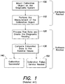
- step 100 a calibration object is mounted and aligned on or in front of the measurement head of the diagnostic system.
- step 110 a measurement of the calibration object is performed (step 110).
- step 110 is referred to as an acquisition since data is acquired from the measurement.
- step 120 the collected data are processed to create a diagnostic reading.
- This diagnostic reading is then compared with expected results based on the known characteristics of the calibration object (step 130). Based on the result of this comparison, the operator is able determine either than the calibration was successful (step 140) or that the calibration failed, indicating a problem with either the calibration object or the diagnostic system (step 150).
- US 2008/0208018 A1 relates to a method and apparatus for the determination of an attribute of the tissue of an individual for example the determination in vivo alcohol concentration using Raman spectroscopy.
- the apparatus comprises a calibration subsystem for determining the relationship between Raman spectra and alcohol concentrations.
- training data has to be collected to determine the tissue Raman spectra properties at one or more wavelengths and the alcohol concentrations.
- a multivariate mathematical model is used to classify attributes or to quantify chemical changes using intrinsic Raman spectra.
- US 2007/0208244 A1 relates to a transcutaneous analyte sensor using a reference data receiving module wherein the reference data includes a set of analyte values entered by a user into an interface and averaged by known methods.
- a reference data comprises a plurality of analyte values obtained from another continuous analyte sensor.
- aspects and embodiments are directed to a method and apparatus to facilitate remote servicing of diagnostic devices, particularly, to remotely verify the software calibration of a diagnostic device following a software upgrade or other remote service operation.
- remotely i.e., from a location other than the location of the diagnostic device
- the usefulness and efficiency of remote software service of diagnostic systems may be enhanced.
- the invention is directed to a method of remotely updating and verifying a calibration status of an instrument that comprises a measurement portion and a computer system coupled to the measurement portion.
- the instrument is a diagnostic system.
- the method comprises acts of providing a software update to the instrument from a remote location via a communications link, without activating the measurement portion of the instrument, performing a calibration check procedure at the instrument, and providing a calibration status indicator that identifies the calibration status of the instrument following the calibration check procedure.
- Performing the calibration check procedure is done without contemporaneously activating the measurement portion of the instrument.
- Performing the calibration check procedure does not include contemporaneously measuring a calibration object with the instrument.
- performing the calibration check procedure includes retrieving stored calibration test data, processing the calibration test data to generate a diagnostic reading, comparing the diagnostic reading to a known correct nominal reading, and based on the comparison, generating the calibration status indicator.
- Performing the calibration check procedure comprises retrieving stored calibration parameters, wherein processing the calibration test data is performed using the calibration parameters.
- Retrieving the stored calibration test data includes retrieving a stored digital image.
- Performing the calibration check procedure includes retrieving stored raw calibration test data, processing the raw calibration test data to generate a diagnostic reading, comparing the diagnostic reading to a known correct nominal reading, and based on the comparison, generating the calibration status indicator.
- Retrieving the stored raw calibration test data may include retrieving a stored digital image.
- Performing the calibration check procedure further comprises retrieving stored calibration parameters, wherein processing the raw calibration test data is performed using the calibration parameters.
- Generating, the calibration status indicator includes generating the calibration status indicator that indicates that the calibration status of the instrument is non-operational. Generating the calibration status indicator may include generating data that identifies one or more corrupted calibration parameters. Generating the calibration status indicator includes generating a calibration status indicator that indicates that the calibration status of the instrument is operational
- Providing the calibration status indicator includes providing the calibration status indicator from the instrument via the communications link.
- Providing calibration status indicator includes providing the calibration status indicator from the instrument to a remote user interface via the communications link.
- the invention is directed to a method of verifying a calibration status of an instrument comprising a processor, the method comprising acts of initiating a calibration check procedure on the processor, retrieving stored raw calibration test data obtained during a previously-performed calibration procedure on the instrument, processing the raw calibration test data with the processor to generate a diagnostic reading, and based on the diagnostic reading, generating a calibration status indicator that indicates whether the calibration check procedure passed or failed.
- Generating the calibration status indicator includes an act of comparing the diagnostic reading to a known nominal reading and generating the calibration status indicator based on a result of the comparing act.
- Processing the raw calibration test data includes processing the raw calibration test data using calibration parameters specific to the instrument.
- Retrieving the stored raw calibration test data includes retrieving a digital image of a calibration test object taken by the instrument during the previously-performed calibration procedure.
- the method further comprises the act of providing the calibration status indicator to a remote user interface via a communication link between the instrument and the remote user interface. Verifying the calibration status of the instrument is performed without contemporaneously measuring a calibration object with the instrument.
- a method of verifying a calibration status of an instrument comprising acts of retrieving stored calibration test data, processing the calibration test data to generate a diagnostic reading, comparing the diagnostic reading to a known nominal reading, and based on the comparison, generating an output indicative of the calibration status of the instrument, wherein the verifying of the calibration status of the instrument is performed without measuring a calibration object with the instrument.
- Retrieving the stored calibration test data and processing the calibration test data to generate the diagnostic reading comprises retrieving stored raw calibration test data, and processing the raw calibration test data to generate the diagnostic reading. Verifying of the calibration status of the instrument is performed without contemporaneously measuring a calibration object with the instrument.
- Retrieving the stored calibration test data may include retrieving a stored digital image.
- Processing the calibration test data includes processing the calibration test data using calibration parameters specific to the instrument.
- Processing the raw calibration test data includes processing the raw calibration test data using calibration parameters specific to the instrument.
- Generating the output indicative of the calibration status of the instrument may include generating an output that identifies a corrupted calibration parameter.
- Generating the output indicative of the calibration status of the instrument includes generating an output that indicates instrument maintenance is required.
- Generating output indicative of the calibration status of the instrument includes generating an output that indicates that the instrument is properly calibrated.
- the computer system comprises a processor configured to receive a software update from a remote location via the communications link, to perform a calibration check procedure of the diagnostic system without activating the measurement portion, and to provide a calibration status indicator that identifies the calibration status of the diagnostic system following the calibration check procedure.
- the processor is configured to verify of the calibration status of the diagnostic system without contemporaneous measurement of a calibration object with the measurement portion.
- the processor is further configured to provide the calibration status indicator to a remote user interface via the communications link.
- the computer system further comprises a storage device, and the processor is configured to perform the calibration check procedure by retrieving stored raw calibration test data from the storage device, processing the raw calibration test data to generate a diagnostic reading, comparing the diagnostic reading to a known nominal reading, and based on the comparison, generating the calibration status indicator.
- a diagnostic system comprises a measurement head, a storage device coupled to the measurement head and which stores raw calibration test data generated by the measurement head, and a processor coupled to the storage device.
- the processor is configured to retrieve the stored raw calibration test data from the storage device without activating the measurement head, to process the raw calibration test data to generate a diagnostic reading, to compare the diagnostic reading to a known nominal reading, and based on the comparison, to generate an output indicative of a calibration status of the diagnostic system.
- the processor is configured to verify a calibration status of the diagnostic system without requiring contemporaneous measurement of a calibration object with the measurement head.
- the diagnostic system further comprises a communications port coupled to a communications link and to the processor, wherein the processor is further configured to transmit the output to a remote location via the communications link.
- the processor is further configured to receive a software upgrade via the communications link and to initiate a calibration check procedure following installation of the software upgrade.
- the diagnostic system may comprise, for example, at least one of a pupilometer, a wavefront sensor, a placido device and a slit scan device.
- the storage device stores calibration parameters specific to the diagnostic system
- the processor is further configured to retrieve at least one calibration parameter from the storage device and to process the raw calibration test data using the at least one calibration parameter to generate the diagnostic reading.
- the output indicates that the calibration status of the diagnostic system is invalid, and contains information indentifying at least one corrupted calibration parameter.
- the stored raw calibration test data includes a stored digital image of a calibration object. The digital image may be acquired during a calibration measurement performed prior to the calibration check procedure.
- Diagnostic systems generally include both hardware and software portion.
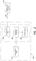
- the hardware of the diagnostic system 200 includes a measurement head 210 that performs measurements on test objects or calibration objects mounted on the system, and a computer or processor 220.
- the computer 220 may be implemented in a variety of ways, including, but not limited to, a general purpose computer coupled to the measurement head 210, and an integrated specialized computer.
- the computer 220 is programmed with software that may perform or control various aspects and functions of the diagnostic system, including, for example, processing software to analyze the data acquired during such a measurement and to generate the diagnostic reading. This software may be periodically updated as part of the maintenance of the diagnostic system.
- the diagnostic system 200 is coupled to user interface at a remote location 230 via a communications link 240 to allow remote upgrades or updates of the software to be performed via the communications link 240.
- the computer 220 may include or be coupled to a communications port 250.
- the communications link 240 include, but are not limited to, a wireless link, a wired link, a fiber optic link, an Internet connection, a network connection, etc.
- the communications port 250 may be implemented using standard systems.
- typical calibration procedures for such diagnostic systems include the mounting of calibration objects on the diagnostic system and comparing the data from a measurement of the calibration object with the nominal values.
- the unique hardware configuration of the diagnostic system is included in the calculation of a measurement analysis. If the calculated values, or diagnostic reading, obtained from the measurement analysis are within a certain acceptance range, then the diagnostic system is considered to be appropriately calibrated, while any deviation from the acceptance range indicates that the calibration status is no longer valid.
- the acceptance range may be defined by ranges of accepted values for each of a variety of calibration parameters. These calibration parameters depend on the diagnostic system and may include, for example, parameters such as the pixel size of the camera, the focal length of the camera, the distance between mirrors, etc., as known to those skilled in the art.
- the calibration parameters are stored in the software of the diagnostic system, it is possible that when a software upgrade is installed, the calibration parameters may be corrupted. Accordingly, when the software is updated, it is important to verify the calibration status of the diagnostic device.
- diagnostic systems can be communicatively coupled to remote locations, such that remote software updates can be performed.
- conventional calibration procedures generally require a trained operator to mount and align the calibration object on the diagnostic system. Therefore, even though the software update can be installed remotely, complete software servicing of the diagnostic system requires an on-site operator to verify the calibration.
- the base for a remote software service is opened.
- the invention avoids the need for having an operator at the diagnostic system to check the calibration status locally whenever a software upgrade is remotely installed.
- the methods and apparatus discussed herein may be used to perform calibration status checks at any time, for example, on a regular basis to detect unintended changes in the diagnostic system, or after events, such as a power failure, or at any other time when verification of the calibration status of the diagnostic system is desired.
- references to "or” may be construed as inclusive so that any terms described using “or” may indicate any of a single, more than one, and all of the described terms. Any references to front and back, left and right, top and bottom, and upper and lower are intended for convenience of description, not to limit the present systems and methods or their components to any one positional or spatial orientation.
- Step 300 includes storing this acquired raw data, referred to as raw calibration test data, in a storage device or memory device 260 forming part of or coupled to the computer 220 of the diagnostic system 200 (see FIG. 2 ).
- the diagnostic system is an optical system configured to measure the human eye
- the calibration objects for each individual diagnostic system are designed to model the applicable characteristics of a real eye. Accordingly, the typical data collected during an acquisition is not significantly different from data originating from a real eye.
- the raw data acquired during step 110 are images taken by cameras (included in the measurement head 210) which operate either in the visible or the infrared range of the spectrum.
- the raw data may include color images or greyscale images that may be stored as digital data.
- the diagnostic systems analyze things other than the eye, (e.g., spectrum analyzers, spectrometers, etc.)
- the acquired raw data may be images or numeric data that can be stored as digital data. Accordingly, although the following discussion may refer to examples of optical diagnostic systems, it is to be appreciated that the invention is not so limited and may be applied to any type of diagnostic system in which digital data is acquired during the calibration procedure.
- step 310 the processing software processes the acquired images and the outcome of the analysis is a set of values which are used to either calibrate or determine the calibration status of the system.
- the measurement of the calibration object includes the unique hardware configuration of the diagnostic system. Accordingly, steps 100 and 110 are "hardware related" in that they rely on and incorporate aspects of the measurement head 210. If no changes are made to the hardware, for example, only a software update is performed, then the hardware-related parts of the calibration procedure (steps 100 and 110) should be stable within the established maintenance interval for the diagnostic system.
- a method of verifying the calibration status of a diagnostic system is independent of the hardware-related portions of a conventional calibration procedure and therefore, may be performed remotely.
- the method uses raw calibration test data from a previously performed calibration procedure that was stored in storage device 260 during step 300 in conjunction with the stored calibration parameters to verify whether the calibration status of the diagnostic system is valid, or whether an event (such as corruption of one or more calibration parameters during a software upgrade) has invalidated the calibration status of the system.
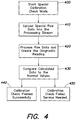
- the diagnostic system enters a calibration check mode to perform the calibration check procedure.
- the calibration check mode may be initiated, for example, by a command issued to the computer 220 from the remote user interface 230.
- the command to initiate the calibration check procedure may be issued responsive to a condition or event such as, but not limited to, following a software upgrade installed on the diagnostic system, a power failure at the location of the diagnostic system, a crash of the computer 220, or as part of a routine maintenance event.
- the calibration check mode may be entered automatically based on policies, such as maintenance schedule, stored on the computer 220 or automatically transmitted to the computer 220 via the communications link 240.
- the processing software uploads the stored raw data set and the stored calibration parameters into the processing stream (step 410).
- steps 100 and 110 of a conventional calibration procedure are replaced with steps 400 and 410 of the calibration check procedure.
- the stored raw data set is processed based on the stored calibration parameters to generate a diagnostic reading (step 420). If the calibration parameters are correct, assuming no other errors in the processing software, the diagnostic reading will correspond to a known set of outcomes. In this case, comparing the calculated diagnostic reading with known correct nominal values (step 430) will yield an expected result, and the processing software generates a calibration status indicator indicating that the calibration check passed successfully (step 440).
- step 430 if any of the calibration parameters are corrupted, or another error has occurred in the processing software, the result of step 430 will indicate that the diagnostic reading is outside of the defined acceptance range.
- the processing software generates a calibration status indicator that indicates that the calibration check has failed, i.e., the calibration status of the diagnostic system is invalid or non-operational, and accordingly, service of the diagnostic system may be required (step 450).
- the computer 220 sends the calibration status indicator to the remote user interface 230 via the communications link 240.
- the calibration check procedure may be initiated remotely and the result of the procedure may be viewed remotely.
- the calibration check procedure does not require a calibration object to be mounted on the diagnostic system and does not require the measurement head of the instrument to be activated. Therefore, the calibration check procedure may be performed without an on-site operator present, and only the portions of the computer 220 required to access the storage device, perform the data processing, and transmit the calibration status indicator to the remote location need be active.
- the method and apparatus allow an operator to perform a remote calibration test of the software components of the diagnostic device.
- the calibration status indicator may contain information that allows a remote operator to diagnose what type of error has occurred, or which calibration parameter has been corrupted. This may allow the remote operator to initiate appropriate maintenance and direct an appropriate technician to service the instrument more quickly and more cost effectively.
- certain calibration parameters are directly related to recognizable features in the processed images or data streams. Accordingly, a change in one of these recognizable features may indicate to the operator which calibration parameter has been affected. For example, in an optical imaging system, the distance between the camera and the calibration object results in defocusing or magnetization of the entire image. Accordingly, if the processed image resulting from step 420 is either out of focus or enlarged/reduced in size compared to the expected result, this may indicate to the operator that the distance calibration parameter is corrupted.
- the computer 220 may transmit the processed data to the remote user interface to be analyzed by the remote operator.
- the calibration status indicator may include the processed data.
- the processing software may identify candidate corrupted calibration parameters based on the result of the comparison step 403, and the calibration status indicator may include information identifying the candidate corrupted parameters.
- the calibration status indicator may be displayed locally by the computer 220 as well as, or instead of, being transmitted to the remote location.
- the computer 220 may store the calibration status indicator for later access by a local operator.
- the raw data sets and calibration parameters are renewed and updated with each service action performed on-site by service personnel.
- the raw data sets and/or calibration parameters may be updated when changes to the system hardware are made or during regular maintenance of the system.
- the raw data sets may also be updated when an operator performs a manual calibration of the diagnostic system, whether part of routine maintenance or not. Updating the stored raw data sets and calibration parameters may ensure that the remote software calibration checks are valid and accurate because current data is used.
- the use of digital data, rather than a physical calibration object, to perform the calibration check procedure may offer several advantages. For example, the characteristics of calibration objects may vary with changing environmental conditions, such as temperature or humidity; whereas stored digital data remains constant over time. In addition, various methods exist for verifying that digital data has in fact remained the same over time, such as, for example, checksum or other procedures. Accordingly, a more accurate calibration check result may be obtained using the stored digital data rather than a physical calibration object.
- the calibration check procedure and method can be applied to a pupilometer.
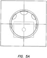
- the reference of the pupilometer is set via a pupil image of a calibration object with a defined aperture. Accordingly, after the alignment of the appropriate calibration object in front of the pupilometer, the image illustrated in FIG. 5A is acquired using the pupil camera.
- FIG. 5 is an image of the pupil size (aperture size) for a calibration object with a defined aperture size of 5 mm. This image is the raw data set that is stored as digital data in step 300. As the size of the physical aperture of the calibration object is known, the analysis of the image needs to provide the specified size. Assuming that the calibration object is positioned correctly, any deviation from this predefined size indicates a problem, for example, wrong configuration of a calibration parameter.
- a pupilometer calibration parameter is the camera pixel to millimeter adjustment factor. Camera images are typically analyzed in pixel coordinates, thus the first information about the pupil diameter will be given in terms of the number of pixels (N pix ) inside the pupil. To determine the physical pupil size in millimeters, the camera-specific pixel-to-mm conversion factor (Pix2mm) is utilized. This conversion factor is an example of a system calibration parameter which is given for any particular system and defined at the production of the system. Any software changes to the system should not modify this parameter. However, as discussed above, it is possible that this calibration parameter may be overwritten by a wrong value during a software upgrade. Corrupting this calibration parameter would lead to incorrectly concluded pupil diameters.
- a remote calibration check may be used for verification of this calibration parameter which defines the number of ⁇ m per camera pixel.
- the digital raw data set corresponding to the pupil camera image of FIG. 5A is uploaded into the processing stream (step 410).
- the aperture size is calculated and, in the analysis step 440, the calculated aperture size is compared to the predefined expected value.
- step 430 of generating the calibration status indicator may include generating a status indicator that indicates whether or not the Pix2mm calibration parameter is correct or not.
- a calibration status indicator is generated, indicating either that the calibration status of the pupilometer is operational (step 440) or non-operational (step 450), and is saved on the computer 220, transmitted to the remote user interface 230, and/or locally displayed by the computer 220.
- the calibration check procedure may be applied to a wavefront sensor.
- a wavefront sensor also referred to as an aberrometer (which term will be used interchangeably herein), is a device that measures a difference in the optical path of light between a deformed wavefront and an ideal, or reference, wavefront. The measurement, when properly processed, yields values for various aberrations in the optical system that the light propagates through, and which deform the wavefront.
- Wavefront sensors are used in a variety of applications, including high-energy lasers, astronomical imaging, and measuring the aberrations of the eye with the goal of improving visual quality.
- One example of a wavefront sensor is the Shack-Hartmann type wavefront sensing instrument that can be used to measure, among other parameters, higher-order ocular aberrations.
- centroid images of test tools are analyzed and the calibration values are saved in the calibration data.
- An example of a raw image of a test tool used to calibrate the wavefront sensor is given in FIG. 6 .
- the raw images are saved as digital raw data sets during step 300.
- the recognized positions of the centroids in combination with the focal length of the lenslet array (f) and the related pitch of the lenslet array determine the outcome of such a Hartmann-Shack sensor.
- the lenslet array parameters are examples of calibration parameters that could be overwritten by wrong values during a software upgrade.
- FIG. 7 there is illustrated a diagram of one example of a wavefront sensor, showing the relationship between values calculated during analysis of the stored raw data and system calibration parameters.
- a wavefront sensor such as discussed in this example measures the tilt of the wavefront or in other words the angle ( ⁇ ) of the wavefront propagating through the system.
- the tilt in the wavefront leads to a spatial shift ( ⁇ x) of the focused bundle of light rays which propagates through the lenslet array and generates the centroid image.
- a remote calibration check of the wavefront sensor can be used to verify the calibration parameter that defines the focal length of the lenslet array (f).
- the remote calibration check may also be used to verify the calibration parameter that defines the camera pixel to millimeter adjustment factor as the calculated displacement value ( ⁇ x) is dependent on the pixel to millimeter adjustment factor.
- the raw Hartman-Shack images ( FIG. 6 ) of calibration spheres are reloaded into the processing stream.
- the processing software analyses the raw images and calculates the diagnostic reading (step 420).
- the diagnostic reading can include a tilt angle ( ⁇ act ). Having a nominal tilt angle ⁇ nom given as the target value, any deviation in the actual determined angle ⁇ act will indicate a deviation of either the system calibration parameter f or the determined value ⁇ x which, as discussed above, is itself dependent on the camera calibration factor Pix2mm.
- step 430 the processing software which checks the diagnostic reading against defined acceptance criteria may check the determined angle ⁇ act against the nominal tilt angle ⁇ nom to determine whether or not the calibration status of the wavefront sensor is valid.
- FIG. 8 is an example of a processed image, obtained following step 420, corresponding to the raw image illustrated in FIG. 6 .
- a calibration status indicator is generated, indicating either that the calibration status of the wavefront sensor is operational (step 440) or non-operational (step 450), and is saved on the computer 220, transmitted to the remote user interface 230, and/or locally displayed by the computer 220.
- the calibration status indicator may indicate an error in either one of the calibration parameters f or Pix2mm, as discussed above.
- the calibration check procedure may be applied to a topographer, such as, for example, the OrbscanTM device available from Bausch and Lomb, Inc.
- the OrbscanTM instrument is an example for a diagnostic system which incorporates two different modules in one system, namely a placido device and a slit scan device.
- the calibration check procedure can be used to remotely verify the calibration status of one or both of these modules.
- the placido device is calibrated using a reference sphere having defined dimensions.
- a reference placido image such as that illustrated in FIG. 9 , of the defined reference sphere.
- the ring positions of the reference sphere are evaluated and stored during step 300.
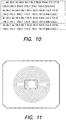
- FIG. 10 illustrates an example of the stored raw digital calibration test data corresponding to the reference image of FIG. 9 . Additionally the gain of the camera can analyzed and checked with the acquired placido image.
- FIG. 11 illustrates an example of a reference placido image for gain analysis.
- the raw calibration test data ( FIG. 10 ) corresponding to the raw placido images ( FIG. 9 ) of the calibration sphere are loaded into the processing steam (step 410).
- the processing software analyzes the images (data) and calculates the related parameters to generate the diagnostic reading (step 420).
- the diagnostic reading then compared with defined acceptance criteria (step 430) to determine whether or not the calibration status of the module is valid.
- the reference image ( FIG. 11 ) is analyzed and the resulting gain measurement is compared with pre-defined ideal gain values.
- FIGS. 12A and 12B An example of a raw slit image and a related elevation map resulting from the processing of the raw image are shown in FIGS. 12A and 12B , respectively.
- the raw slit images of the calibration sphere are uploaded into the processing stream (step 410).
- the images are analyzed and the related diagnostic reading calculated (step 420).
- the diagnostic reading is compared to a known correct nominal reading (step 430) and a calibration status indicator is generated.
- the calibration status indicator may combine the results from the calibration check of both the placido device and the slit scan device to indicate whether or not the calibration status of the topographer as a whole is valid.
- the calibration status indicator may include individual indications as to whether or not the calibration statuses of the individual modules are valid.
- embodiments of the calibration check procedure may be applies to any kind of diagnostic system which is based on a type of image acquisition technology.
- non-image data streams may similarly be injected into the processing step of embodiments of the calibration check method to replicate other kinds of diagnostic data, such as, for example, an A-Scan generated by a partial coherence interferometer used for the determination of the eye length.
Priority Applications (1)
| Application Number | Priority Date | Filing Date | Title |
|---|---|---|---|
| PL09801612T PL2375963T3 (pl) | 2008-12-17 | 2009-12-17 | Sposób i urządzenie do przeprowadzania zdalnej weryfikacji kalibracji |
Applications Claiming Priority (2)
| Application Number | Priority Date | Filing Date | Title |
|---|---|---|---|
| US12/336,893 US7895011B2 (en) | 2008-12-17 | 2008-12-17 | Method and apparatus for performing remote calibration verification |
| PCT/US2009/068353 WO2010071796A1 (en) | 2008-12-17 | 2009-12-17 | Method and apparatus for performing remote calibration verification |
Publications (2)
| Publication Number | Publication Date |
|---|---|
| EP2375963A1 EP2375963A1 (en) | 2011-10-19 |
| EP2375963B1 true EP2375963B1 (en) | 2017-02-15 |
Family
ID=41719007
Family Applications (1)
| Application Number | Title | Priority Date | Filing Date |
|---|---|---|---|
| EP09801612.4A Not-in-force EP2375963B1 (en) | 2008-12-17 | 2009-12-17 | Method and apparatus for performing remote calibration verification |
Country Status (10)
| Country | Link |
|---|---|
| US (1) | US7895011B2 (es) |
| EP (1) | EP2375963B1 (es) |
| JP (1) | JP2012512008A (es) |
| KR (1) | KR101722575B1 (es) |
| CN (1) | CN102256535B (es) |
| AU (1) | AU2009327407B2 (es) |
| CA (1) | CA2745222C (es) |
| ES (1) | ES2617652T3 (es) |
| PL (1) | PL2375963T3 (es) |
| WO (1) | WO2010071796A1 (es) |
Families Citing this family (20)
| Publication number | Priority date | Publication date | Assignee | Title |
|---|---|---|---|---|
| FR2928387B1 (fr) * | 2008-03-10 | 2012-11-16 | Westline | Procede et systeme de calibration automatique des engins de terrassement |
| EP2370644A4 (en) * | 2008-11-26 | 2014-03-05 | Volvo Constr Equip Ab | METHOD FOR CALIBRATING ANGLE SENSOR AND VEHICLE WITH ANGLE SENSOR |
| US20130197842A1 (en) * | 2012-01-31 | 2013-08-01 | Caterpillar Inc. | Streamlined parts approval process |
| CN103514087B (zh) * | 2012-06-18 | 2016-09-28 | 中国电子科技集团公司第四十一研究所 | 一种测量仪器的软件仿真验证系统 |
| US9571350B2 (en) | 2013-01-23 | 2017-02-14 | International Business Machines Corporation | Network element diagnostic evaluation |
| CN104739360A (zh) * | 2015-04-13 | 2015-07-01 | 张仕郎 | 远程验光系统及方法 |
| US10846076B2 (en) * | 2016-10-11 | 2020-11-24 | Barfield, Inc. | Remote application update of measurement device field firmware |
| US10696906B2 (en) | 2017-09-29 | 2020-06-30 | Marathon Petroleum Company Lp | Tower bottoms coke catching device |
| US20200096363A1 (en) * | 2018-09-26 | 2020-03-26 | Infineon Technologies Ag | Providing compensation parameters for sensor integrated circuits |
| US11975316B2 (en) | 2019-05-09 | 2024-05-07 | Marathon Petroleum Company Lp | Methods and reforming systems for re-dispersing platinum on reforming catalyst |
| CN112577542A (zh) * | 2019-09-27 | 2021-03-30 | 广州中测检测技术有限公司 | 计量器具及计量器具的远程量传/溯源方法 |
| CA3109675A1 (en) | 2020-02-19 | 2021-08-19 | Marathon Petroleum Company Lp | Low sulfur fuel oil blends for stability enhancement and associated methods |
| DE102020004841A1 (de) | 2020-08-07 | 2022-02-10 | Mettler-Toledo Gmbh | Verfahren und Vorrichtung zur Ermittlung einer beobachtbaren Eigenschaft eines Objekts |
| US11905468B2 (en) | 2021-02-25 | 2024-02-20 | Marathon Petroleum Company Lp | Assemblies and methods for enhancing control of fluid catalytic cracking (FCC) processes using spectroscopic analyzers |
| US11702600B2 (en) | 2021-02-25 | 2023-07-18 | Marathon Petroleum Company Lp | Assemblies and methods for enhancing fluid catalytic cracking (FCC) processes during the FCC process using spectroscopic analyzers |
| US11898109B2 (en) | 2021-02-25 | 2024-02-13 | Marathon Petroleum Company Lp | Assemblies and methods for enhancing control of hydrotreating and fluid catalytic cracking (FCC) processes using spectroscopic analyzers |
| US20220268694A1 (en) | 2021-02-25 | 2022-08-25 | Marathon Petroleum Company Lp | Methods and assemblies for determining and using standardized spectral responses for calibration of spectroscopic analyzers |
| CN113093081B (zh) * | 2021-06-09 | 2021-08-17 | 深圳市鼎阳科技股份有限公司 | 用于频谱分析仪的校准和pv方法及生产系统 |
| US11692141B2 (en) | 2021-10-10 | 2023-07-04 | Marathon Petroleum Company Lp | Methods and systems for enhancing processing of hydrocarbons in a fluid catalytic cracking unit using a renewable additive |
| CA3188122A1 (en) | 2022-01-31 | 2023-07-31 | Marathon Petroleum Company Lp | Systems and methods for reducing rendered fats pour point |
Family Cites Families (28)
| Publication number | Priority date | Publication date | Assignee | Title |
|---|---|---|---|---|
| AU8327991A (en) | 1990-07-12 | 1992-02-04 | Light Source Computer Images, Inc. | Method and structure for calibrating a computer generated image |
| AU716040B2 (en) * | 1993-06-24 | 2000-02-17 | Bausch & Lomb Incorporated | Ophthalmic pachymeter and method of making ophthalmic determinations |
| US6487513B1 (en) * | 1995-06-07 | 2002-11-26 | Toshiba America Medical Systems, Inc. | Diagnostic test unit network and system |
| US5798518A (en) | 1995-07-28 | 1998-08-25 | Laserscope | Medical laser calibration system and method |
| US5856195A (en) * | 1996-10-30 | 1999-01-05 | Bayer Corporation | Method and apparatus for calibrating a sensor element |
| JP3630973B2 (ja) * | 1998-02-27 | 2005-03-23 | 株式会社ニデック | 眼科装置及び眼科装置における検眼情報の保存方法 |
| US6175752B1 (en) * | 1998-04-30 | 2001-01-16 | Therasense, Inc. | Analyte monitoring device and methods of use |
| US6022109A (en) | 1998-12-10 | 2000-02-08 | Dal Santo; John P. | Hand-held Pupilometer |
| JP2003502090A (ja) * | 1999-06-17 | 2003-01-21 | メドトロニック ミニメド インコーポレイテッド | 検体センサと共に使用するための特性モニタシステム |
| JP2003508145A (ja) * | 1999-09-03 | 2003-03-04 | テンシス メディカル インコーポレイテッド | 生理学的パラメータ用スマート・センサおよび方法 |
| JP2003534035A (ja) | 2000-03-15 | 2003-11-18 | オーソソフト インコーポレイテッド | コンピュータ支援手術器具の自動校正システム |
| JP2002292853A (ja) | 2001-03-29 | 2002-10-09 | Tomoegawa Paper Co Ltd | マーキングシステム、マーキング方法およびマーキング装置 |
| US8581697B2 (en) | 2001-04-11 | 2013-11-12 | Trutouch Technologies Inc. | Apparatuses for noninvasive determination of in vivo alcohol concentration using raman spectroscopy |
| US6637884B2 (en) | 2001-12-14 | 2003-10-28 | Bausch & Lomb Incorporated | Aberrometer calibration |
| AU2003210974A1 (en) | 2002-02-11 | 2003-09-04 | Visx, Inc. | Method and device for calibrating an optical wavefront system |
| JP2004159734A (ja) * | 2002-11-11 | 2004-06-10 | Canon Inc | 眼科装置 |
| JP2004272762A (ja) * | 2003-03-11 | 2004-09-30 | Topcon Corp | 医療用ネットワークシステム、情報処理装置、課金処理方法、そのためのプログラム、および、このプログラムを記録した情報記録媒体 |
| JP4526782B2 (ja) | 2003-05-15 | 2010-08-18 | 株式会社堀場製作所 | 測定装置 |
| US8160669B2 (en) | 2003-08-01 | 2012-04-17 | Dexcom, Inc. | Transcutaneous analyte sensor |
| US6931327B2 (en) * | 2003-08-01 | 2005-08-16 | Dexcom, Inc. | System and methods for processing analyte sensor data |
| US7347549B2 (en) * | 2003-12-10 | 2008-03-25 | Bausch & Lomb Incorporated | Rapid switching slit scan image capture system |
| JP2005189031A (ja) * | 2003-12-25 | 2005-07-14 | Shimadzu Corp | 分析計 |
| KR100686659B1 (ko) * | 2004-02-19 | 2007-02-27 | 너스킨 인터어내셔날 인코포레이팃드 | 바이오 광 피드백 제어 장치 및 방법 |
| JP2006134374A (ja) | 2004-11-02 | 2006-05-25 | Nec Micro Systems Ltd | 半導体装置及び半導体装置のテスト方法 |
| US7062397B1 (en) | 2004-12-23 | 2006-06-13 | Agilent Technologies, Inc. | Recursive calibration |
| GB2422197B (en) | 2005-05-17 | 2007-08-08 | Bio Nano Sensium Technologies | Sensor calibration |
| US7652749B2 (en) | 2006-02-14 | 2010-01-26 | Asml Netherlands B.V. | Software upgrades in a lithographic apparatus |
| JP2007252413A (ja) * | 2006-03-20 | 2007-10-04 | Topcon Corp | 眼科用測定装置 |
-
2008
- 2008-12-17 US US12/336,893 patent/US7895011B2/en not_active Expired - Fee Related
-
2009
- 2009-12-17 EP EP09801612.4A patent/EP2375963B1/en not_active Not-in-force
- 2009-12-17 AU AU2009327407A patent/AU2009327407B2/en not_active Ceased
- 2009-12-17 CA CA2745222A patent/CA2745222C/en not_active Expired - Fee Related
- 2009-12-17 CN CN200980150878.0A patent/CN102256535B/zh not_active Expired - Fee Related
- 2009-12-17 JP JP2011542414A patent/JP2012512008A/ja not_active Ceased
- 2009-12-17 PL PL09801612T patent/PL2375963T3/pl unknown
- 2009-12-17 KR KR1020117016599A patent/KR101722575B1/ko active IP Right Grant
- 2009-12-17 WO PCT/US2009/068353 patent/WO2010071796A1/en active Application Filing
- 2009-12-17 ES ES09801612.4T patent/ES2617652T3/es active Active
Non-Patent Citations (1)
| Title |
|---|
| None * |
Also Published As
| Publication number | Publication date |
|---|---|
| CN102256535B (zh) | 2014-08-06 |
| US20100153047A1 (en) | 2010-06-17 |
| JP2012512008A (ja) | 2012-05-31 |
| KR20110106377A (ko) | 2011-09-28 |
| PL2375963T3 (pl) | 2017-10-31 |
| CA2745222A1 (en) | 2010-06-24 |
| KR101722575B1 (ko) | 2017-04-03 |
| WO2010071796A1 (en) | 2010-06-24 |
| ES2617652T3 (es) | 2017-06-19 |
| AU2009327407B2 (en) | 2015-10-29 |
| AU2009327407A1 (en) | 2011-06-23 |
| CA2745222C (en) | 2016-07-05 |
| CN102256535A (zh) | 2011-11-23 |
| US7895011B2 (en) | 2011-02-22 |
| EP2375963A1 (en) | 2011-10-19 |
Similar Documents
| Publication | Publication Date | Title |
|---|---|---|
| EP2375963B1 (en) | Method and apparatus for performing remote calibration verification | |
| US6808266B2 (en) | Objective manifest refraction | |
| CN111295129B (zh) | 视敏度检查 | |
| US20230263390A1 (en) | Apparatus and method for self-correcting objective refractometry | |
| EP2835098A1 (en) | Ophthalmic measurement device, and ophthalmic measurement system equipped with ophthalmic measurement device | |
| JP2021501008A6 (ja) | 視力検査 | |
| US9775507B2 (en) | Method of evaluating quality of vision in examinee's eye and storage medium | |
| US7110582B1 (en) | Method for determining binocular balance and disorders of binocularity of an individual or clinical groups of individuals | |
| CN115553707A (zh) | 一种基于眼动追踪的对比敏感度测量方法及设备 | |
| CN110367925A (zh) | 主客观一体式诊断性验光装置及验光方法 | |
| US20230255473A1 (en) | Integrated apparatus for visual function testing and method thereof | |
| US20220125297A1 (en) | Device calibration via a projective transform matrix | |
| WO2017006750A1 (ja) | 標準眼モジュール装置および視野計評価方法 | |
| EP4009099A1 (en) | Measurement method and judgement method for visual behavior, design method and manufacturing method for progressive power lens, measurement system for visual behavior, and design system for progressive power lens | |
| US11497398B2 (en) | Method and device for calibrating optical diagnostic system | |
| US20220125298A1 (en) | Active calibration of head-mounted displays | |
| US11484196B2 (en) | Method and apparatus for refraction and vision measurement | |
| CN117297539A (zh) | 一种平面眼动的校准方法、装置、电子设备及存储介质 | |
| EP4236755A1 (en) | Systems and methods for visual field testing in head-mounted displays | |
| WO2022019908A1 (en) | Method and apparatus for refraction and vision measurement |
Legal Events
| Date | Code | Title | Description |
|---|---|---|---|
| PUAI | Public reference made under article 153(3) epc to a published international application that has entered the european phase |
Free format text: ORIGINAL CODE: 0009012 |
|
| 17P | Request for examination filed |
Effective date: 20110713 |
|
| AK | Designated contracting states |
Kind code of ref document: A1 Designated state(s): AT BE BG CH CY CZ DE DK EE ES FI FR GB GR HR HU IE IS IT LI LT LU LV MC MK MT NL NO PL PT RO SE SI SK SM TR |
|
| DAX | Request for extension of the european patent (deleted) | ||
| 17Q | First examination report despatched |
Effective date: 20140812 |
|
| RIC1 | Information provided on ipc code assigned before grant |
Ipc: A61B 3/135 20060101ALN20160426BHEP Ipc: G06F 19/00 20110101ALI20160426BHEP Ipc: A61B 3/10 20060101AFI20160426BHEP |
|
| GRAP | Despatch of communication of intention to grant a patent |
Free format text: ORIGINAL CODE: EPIDOSNIGR1 |
|
| RIC1 | Information provided on ipc code assigned before grant |
Ipc: G06F 19/00 20110101ALI20160629BHEP Ipc: A61B 3/10 20060101AFI20160629BHEP Ipc: A61B 3/135 20060101ALN20160629BHEP |
|
| INTG | Intention to grant announced |
Effective date: 20160713 |
|
| GRAS | Grant fee paid |
Free format text: ORIGINAL CODE: EPIDOSNIGR3 |
|
| GRAJ | Information related to disapproval of communication of intention to grant by the applicant or resumption of examination proceedings by the epo deleted |
Free format text: ORIGINAL CODE: EPIDOSDIGR1 |
|
| GRAL | Information related to payment of fee for publishing/printing deleted |
Free format text: ORIGINAL CODE: EPIDOSDIGR3 |
|
| REG | Reference to a national code |
Ref country code: DE Ref legal event code: R079 Ref document number: 602009044229 Country of ref document: DE Free format text: PREVIOUS MAIN CLASS: A61B0003107000 Ipc: A61B0003100000 |
|
| GRAR | Information related to intention to grant a patent recorded |
Free format text: ORIGINAL CODE: EPIDOSNIGR71 |
|
| INTC | Intention to grant announced (deleted) | ||
| RIC1 | Information provided on ipc code assigned before grant |
Ipc: A61B 3/135 20060101ALN20161207BHEP Ipc: A61B 3/10 20060101AFI20161207BHEP Ipc: G06F 19/00 20110101ALI20161207BHEP |
|
| GRAA | (expected) grant |
Free format text: ORIGINAL CODE: 0009210 |
|
| AK | Designated contracting states |
Kind code of ref document: B1 Designated state(s): AT BE BG CH CY CZ DE DK EE ES FI FR GB GR HR HU IE IS IT LI LT LU LV MC MK MT NL NO PL PT RO SE SI SK SM TR |
|
| INTG | Intention to grant announced |
Effective date: 20170106 |
|
| REG | Reference to a national code |
Ref country code: CH Ref legal event code: EP Ref country code: GB Ref legal event code: FG4D |
|
| REG | Reference to a national code |
Ref country code: IE Ref legal event code: FG4D |
|
| REG | Reference to a national code |
Ref country code: AT Ref legal event code: REF Ref document number: 867434 Country of ref document: AT Kind code of ref document: T Effective date: 20170315 |
|
| REG | Reference to a national code |
Ref country code: DE Ref legal event code: R096 Ref document number: 602009044229 Country of ref document: DE |
|
| REG | Reference to a national code |
Ref country code: ES Ref legal event code: FG2A Ref document number: 2617652 Country of ref document: ES Kind code of ref document: T3 Effective date: 20170619 |
|
| REG | Reference to a national code |
Ref country code: NL Ref legal event code: MP Effective date: 20170215 |
|
| REG | Reference to a national code |
Ref country code: LT Ref legal event code: MG4D |
|
| REG | Reference to a national code |
Ref country code: AT Ref legal event code: MK05 Ref document number: 867434 Country of ref document: AT Kind code of ref document: T Effective date: 20170215 |
|
| PG25 | Lapsed in a contracting state [announced via postgrant information from national office to epo] |
Ref country code: FI Free format text: LAPSE BECAUSE OF FAILURE TO SUBMIT A TRANSLATION OF THE DESCRIPTION OR TO PAY THE FEE WITHIN THE PRESCRIBED TIME-LIMIT Effective date: 20170215 Ref country code: LT Free format text: LAPSE BECAUSE OF FAILURE TO SUBMIT A TRANSLATION OF THE DESCRIPTION OR TO PAY THE FEE WITHIN THE PRESCRIBED TIME-LIMIT Effective date: 20170215 Ref country code: HR Free format text: LAPSE BECAUSE OF FAILURE TO SUBMIT A TRANSLATION OF THE DESCRIPTION OR TO PAY THE FEE WITHIN THE PRESCRIBED TIME-LIMIT Effective date: 20170215 Ref country code: NO Free format text: LAPSE BECAUSE OF FAILURE TO SUBMIT A TRANSLATION OF THE DESCRIPTION OR TO PAY THE FEE WITHIN THE PRESCRIBED TIME-LIMIT Effective date: 20170515 Ref country code: GR Free format text: LAPSE BECAUSE OF FAILURE TO SUBMIT A TRANSLATION OF THE DESCRIPTION OR TO PAY THE FEE WITHIN THE PRESCRIBED TIME-LIMIT Effective date: 20170516 |
|
| PG25 | Lapsed in a contracting state [announced via postgrant information from national office to epo] |
Ref country code: SE Free format text: LAPSE BECAUSE OF FAILURE TO SUBMIT A TRANSLATION OF THE DESCRIPTION OR TO PAY THE FEE WITHIN THE PRESCRIBED TIME-LIMIT Effective date: 20170215 Ref country code: AT Free format text: LAPSE BECAUSE OF FAILURE TO SUBMIT A TRANSLATION OF THE DESCRIPTION OR TO PAY THE FEE WITHIN THE PRESCRIBED TIME-LIMIT Effective date: 20170215 Ref country code: LV Free format text: LAPSE BECAUSE OF FAILURE TO SUBMIT A TRANSLATION OF THE DESCRIPTION OR TO PAY THE FEE WITHIN THE PRESCRIBED TIME-LIMIT Effective date: 20170215 Ref country code: BG Free format text: LAPSE BECAUSE OF FAILURE TO SUBMIT A TRANSLATION OF THE DESCRIPTION OR TO PAY THE FEE WITHIN THE PRESCRIBED TIME-LIMIT Effective date: 20170515 Ref country code: NL Free format text: LAPSE BECAUSE OF FAILURE TO SUBMIT A TRANSLATION OF THE DESCRIPTION OR TO PAY THE FEE WITHIN THE PRESCRIBED TIME-LIMIT Effective date: 20170215 Ref country code: PT Free format text: LAPSE BECAUSE OF FAILURE TO SUBMIT A TRANSLATION OF THE DESCRIPTION OR TO PAY THE FEE WITHIN THE PRESCRIBED TIME-LIMIT Effective date: 20170615 |
|
| PG25 | Lapsed in a contracting state [announced via postgrant information from national office to epo] |
Ref country code: RO Free format text: LAPSE BECAUSE OF FAILURE TO SUBMIT A TRANSLATION OF THE DESCRIPTION OR TO PAY THE FEE WITHIN THE PRESCRIBED TIME-LIMIT Effective date: 20170215 Ref country code: SK Free format text: LAPSE BECAUSE OF FAILURE TO SUBMIT A TRANSLATION OF THE DESCRIPTION OR TO PAY THE FEE WITHIN THE PRESCRIBED TIME-LIMIT Effective date: 20170215 Ref country code: EE Free format text: LAPSE BECAUSE OF FAILURE TO SUBMIT A TRANSLATION OF THE DESCRIPTION OR TO PAY THE FEE WITHIN THE PRESCRIBED TIME-LIMIT Effective date: 20170215 Ref country code: CZ Free format text: LAPSE BECAUSE OF FAILURE TO SUBMIT A TRANSLATION OF THE DESCRIPTION OR TO PAY THE FEE WITHIN THE PRESCRIBED TIME-LIMIT Effective date: 20170215 |
|
| REG | Reference to a national code |
Ref country code: DE Ref legal event code: R097 Ref document number: 602009044229 Country of ref document: DE |
|
| REG | Reference to a national code |
Ref country code: FR Ref legal event code: PLFP Year of fee payment: 9 |
|
| PG25 | Lapsed in a contracting state [announced via postgrant information from national office to epo] |
Ref country code: DK Free format text: LAPSE BECAUSE OF FAILURE TO SUBMIT A TRANSLATION OF THE DESCRIPTION OR TO PAY THE FEE WITHIN THE PRESCRIBED TIME-LIMIT Effective date: 20170215 Ref country code: SM Free format text: LAPSE BECAUSE OF FAILURE TO SUBMIT A TRANSLATION OF THE DESCRIPTION OR TO PAY THE FEE WITHIN THE PRESCRIBED TIME-LIMIT Effective date: 20170215 |
|
| PGFP | Annual fee paid to national office [announced via postgrant information from national office to epo] |
Ref country code: PL Payment date: 20170925 Year of fee payment: 9 |
|
| PLBE | No opposition filed within time limit |
Free format text: ORIGINAL CODE: 0009261 |
|
| STAA | Information on the status of an ep patent application or granted ep patent |
Free format text: STATUS: NO OPPOSITION FILED WITHIN TIME LIMIT |
|
| 26N | No opposition filed |
Effective date: 20171116 |
|
| PGFP | Annual fee paid to national office [announced via postgrant information from national office to epo] |
Ref country code: FR Payment date: 20171120 Year of fee payment: 9 |
|
| PG25 | Lapsed in a contracting state [announced via postgrant information from national office to epo] |
Ref country code: SI Free format text: LAPSE BECAUSE OF FAILURE TO SUBMIT A TRANSLATION OF THE DESCRIPTION OR TO PAY THE FEE WITHIN THE PRESCRIBED TIME-LIMIT Effective date: 20170215 |
|
| PGFP | Annual fee paid to national office [announced via postgrant information from national office to epo] |
Ref country code: GB Payment date: 20171128 Year of fee payment: 9 |
|
| PGFP | Annual fee paid to national office [announced via postgrant information from national office to epo] |
Ref country code: ES Payment date: 20180105 Year of fee payment: 9 Ref country code: DE Payment date: 20171221 Year of fee payment: 9 |
|
| PGFP | Annual fee paid to national office [announced via postgrant information from national office to epo] |
Ref country code: IT Payment date: 20171220 Year of fee payment: 9 |
|
| REG | Reference to a national code |
Ref country code: CH Ref legal event code: PL |
|
| REG | Reference to a national code |
Ref country code: IE Ref legal event code: MM4A |
|
| PG25 | Lapsed in a contracting state [announced via postgrant information from national office to epo] |
Ref country code: MT Free format text: LAPSE BECAUSE OF NON-PAYMENT OF DUE FEES Effective date: 20171217 Ref country code: LU Free format text: LAPSE BECAUSE OF NON-PAYMENT OF DUE FEES Effective date: 20171217 |
|
| REG | Reference to a national code |
Ref country code: BE Ref legal event code: MM Effective date: 20171231 |
|
| PG25 | Lapsed in a contracting state [announced via postgrant information from national office to epo] |
Ref country code: IE Free format text: LAPSE BECAUSE OF NON-PAYMENT OF DUE FEES Effective date: 20171217 |
|
| PG25 | Lapsed in a contracting state [announced via postgrant information from national office to epo] |
Ref country code: BE Free format text: LAPSE BECAUSE OF NON-PAYMENT OF DUE FEES Effective date: 20171231 Ref country code: CH Free format text: LAPSE BECAUSE OF NON-PAYMENT OF DUE FEES Effective date: 20171231 Ref country code: LI Free format text: LAPSE BECAUSE OF NON-PAYMENT OF DUE FEES Effective date: 20171231 |
|
| PG25 | Lapsed in a contracting state [announced via postgrant information from national office to epo] |
Ref country code: MC Free format text: LAPSE BECAUSE OF FAILURE TO SUBMIT A TRANSLATION OF THE DESCRIPTION OR TO PAY THE FEE WITHIN THE PRESCRIBED TIME-LIMIT Effective date: 20170215 Ref country code: HU Free format text: LAPSE BECAUSE OF FAILURE TO SUBMIT A TRANSLATION OF THE DESCRIPTION OR TO PAY THE FEE WITHIN THE PRESCRIBED TIME-LIMIT; INVALID AB INITIO Effective date: 20091217 |
|
| REG | Reference to a national code |
Ref country code: DE Ref legal event code: R119 Ref document number: 602009044229 Country of ref document: DE |
|
| GBPC | Gb: european patent ceased through non-payment of renewal fee |
Effective date: 20181217 |
|
| PG25 | Lapsed in a contracting state [announced via postgrant information from national office to epo] |
Ref country code: CY Free format text: LAPSE BECAUSE OF NON-PAYMENT OF DUE FEES Effective date: 20170215 Ref country code: FR Free format text: LAPSE BECAUSE OF NON-PAYMENT OF DUE FEES Effective date: 20181231 Ref country code: IT Free format text: LAPSE BECAUSE OF NON-PAYMENT OF DUE FEES Effective date: 20181217 Ref country code: DE Free format text: LAPSE BECAUSE OF NON-PAYMENT OF DUE FEES Effective date: 20190702 |
|
| PG25 | Lapsed in a contracting state [announced via postgrant information from national office to epo] |
Ref country code: MK Free format text: LAPSE BECAUSE OF FAILURE TO SUBMIT A TRANSLATION OF THE DESCRIPTION OR TO PAY THE FEE WITHIN THE PRESCRIBED TIME-LIMIT Effective date: 20170215 |
|
| PG25 | Lapsed in a contracting state [announced via postgrant information from national office to epo] |
Ref country code: GB Free format text: LAPSE BECAUSE OF NON-PAYMENT OF DUE FEES Effective date: 20181217 |
|
| REG | Reference to a national code |
Ref country code: ES Ref legal event code: FD2A Effective date: 20200205 |
|
| PG25 | Lapsed in a contracting state [announced via postgrant information from national office to epo] |
Ref country code: TR Free format text: LAPSE BECAUSE OF FAILURE TO SUBMIT A TRANSLATION OF THE DESCRIPTION OR TO PAY THE FEE WITHIN THE PRESCRIBED TIME-LIMIT Effective date: 20170215 |
|
| PG25 | Lapsed in a contracting state [announced via postgrant information from national office to epo] |
Ref country code: ES Free format text: LAPSE BECAUSE OF NON-PAYMENT OF DUE FEES Effective date: 20181218 |
|
| PG25 | Lapsed in a contracting state [announced via postgrant information from national office to epo] |
Ref country code: IS Free format text: LAPSE BECAUSE OF FAILURE TO SUBMIT A TRANSLATION OF THE DESCRIPTION OR TO PAY THE FEE WITHIN THE PRESCRIBED TIME-LIMIT Effective date: 20170615 |
|
| PG25 | Lapsed in a contracting state [announced via postgrant information from national office to epo] |
Ref country code: PL Free format text: LAPSE BECAUSE OF NON-PAYMENT OF DUE FEES Effective date: 20181217 |