EP2373957B1 - Verfahren zur bestimmung eines flüssigkeitsstandes in einem behälter durch bilderzeugung - Google Patents
Verfahren zur bestimmung eines flüssigkeitsstandes in einem behälter durch bilderzeugung Download PDFInfo
- Publication number
- EP2373957B1 EP2373957B1 EP09837845.8A EP09837845A EP2373957B1 EP 2373957 B1 EP2373957 B1 EP 2373957B1 EP 09837845 A EP09837845 A EP 09837845A EP 2373957 B1 EP2373957 B1 EP 2373957B1
- Authority
- EP
- European Patent Office
- Prior art keywords
- sample
- container
- image
- peaks
- dimensional array
- Prior art date
- Legal status (The legal status is an assumption and is not a legal conclusion. Google has not performed a legal analysis and makes no representation as to the accuracy of the status listed.)
- Active
Links
Images


Classifications
-
- G—PHYSICS
- G01—MEASURING; TESTING
- G01F—MEASURING VOLUME, VOLUME FLOW, MASS FLOW OR LIQUID LEVEL; METERING BY VOLUME
- G01F23/00—Indicating or measuring liquid level or level of fluent solid material, e.g. indicating in terms of volume or indicating by means of an alarm
- G01F23/22—Indicating or measuring liquid level or level of fluent solid material, e.g. indicating in terms of volume or indicating by means of an alarm by measuring physical variables, other than linear dimensions, pressure or weight, dependent on the level to be measured, e.g. by difference of heat transfer of steam or water
- G01F23/28—Indicating or measuring liquid level or level of fluent solid material, e.g. indicating in terms of volume or indicating by means of an alarm by measuring physical variables, other than linear dimensions, pressure or weight, dependent on the level to be measured, e.g. by difference of heat transfer of steam or water by measuring the variations of parameters of electromagnetic or acoustic waves applied directly to the liquid or fluent solid material
- G01F23/284—Electromagnetic waves
- G01F23/292—Light, e.g. infrared or ultraviolet
-
- G—PHYSICS
- G01—MEASURING; TESTING
- G01F—MEASURING VOLUME, VOLUME FLOW, MASS FLOW OR LIQUID LEVEL; METERING BY VOLUME
- G01F23/00—Indicating or measuring liquid level or level of fluent solid material, e.g. indicating in terms of volume or indicating by means of an alarm
- G01F23/80—Arrangements for signal processing
- G01F23/802—Particular electronic circuits for digital processing equipment
- G01F23/804—Particular electronic circuits for digital processing equipment containing circuits handling parameters other than liquid level
Definitions
- the present invention relates to liquid volume measurement, and more specifically to methods for detecting and measuring the level of a liquid in a container using imaging.
- samples may include, for example, blood, urine, DNA, feces, tissue, etc.
- samples may include, for example, air, water, soil, etc.
- the sample may be mixed with a reagent to produce an outcome.
- the mixing may take place outside of a patient's body, for example.
- the different tests may require different quantities of a sample, which may be collected in various containers. In some instances, the container may have a sample capacity greater than is necessary for a particular test.
- a method for detecting the position of the interface between two media in a container is disclosed in WO 03/060433 A2 .
- the container is irradiated with light, the radiation that passes through the container is captured and converted into a video image.
- the entire video image is then evaluated, optionally after digitalization, in order to determine the position of the interface in terms of height.
- the electro-capacitive method may be another conventional method for sensing a liquid level of a sample.
- a probe may be inserted into the sample, thereby contacting the sample, which may be destructive to the sample to some degree. Additionally, contact with the sample may increase the possibility of carryover between the different samples being tested. In other words, some of a first sample tested may remain on the probes used with the capacitive method, for example, and be carried-over to the second sample being tested by the same probes.
- the electro-capacitive method detects the level of the sample by measuring the position of the probe at the moment of contact with the sample that in turn produces a change in capacitance on the probe.
- the electro-capacitive method may be limited by the difficulty in detecting very small changes in capacitance, as well as unavoidable bulk parasitic changes and interferences in the environment when detecting the liquid level of the sample (ie. foam or dust on the surface of the sample; or turbulence in the sample).
- Another conventional way to sense the liquid level of a sample may be to use ultrasound, whereby a sound pulse is sent into the sample and a sensor examines time for an echo to return.
- ultrasound no contact with the sample is necessary.
- ultrasonic level sensing may be difficult to implement, as it depends on air properties that may change with temperature and humidity. Additionally, the resolution associated with ultrasonic level sensing may be fairly low. Accordingly, a need exists for an improved method and apparatus for determining the amount of sample in a container.
- the method of the present invention may be performed by a system for determining a level of a sample.
- the system includes an image capture apparatus adapted to capture the image of a sample in a container, wherein the image is represented as a two dimensional array of intensities of light; and a controller coupled to the image capture apparatus, wherein the controller is adapted to extract an area of interest from the image, apply a filter to the area of interest, collapse the filtered area of interest into a one dimensional array, apply a mask to the one dimensional array, and determine the level of the sample in the container based on the masked one dimensional array.
- a method for determining a liquid level of a sample in a container comprises: capturing an image of a sample housed in a container, wherein the image is represented as a two dimensional array of intensities of light; extracting an area of interest from the image to obtain a two dimensional array of interest; processing the two dimensional array of interest with a differential filter to obtain a differentially filtered two dimensional array; splitting the differentially filtered two dimensional array into "n" narrower vertical arrays; collapsing the "n” two dimensional vertical arrays horizontally to form “n” one dimensional differential arrays; applying a mask to the "n” one dimensional differential arrays to account for noise; analyzing each of the resulting "n” masked vertical one dimensional differential arrays to determine the presence of peaks; counting and combining, per vertical unit, the peaks resulting from the analysis; forming a histogram from the combined and counted peaks to obtain a frequency of peak appearance per vertical unit; further processing
- the method of the present invention may be used for determining the presence and amount of foam on a surface of a sample wherein a range of continuous concentration of peaks is detected in at least one direction moving away from the interface, and wherein the continuous concentration is the foam.
- the present invention provides methods for sensing the liquid level of a sample in a container.
- the present invention provides a method whereby an image of the sample retained in a container is captured.
- the image may be captured by any conventional means (e.g. video camera, digital still camera, line scanner, etc.).
- the container may be made from a transparent material to allow the passage of light through the sample. By capturing an image of the sample, the sample may be observed/measured without physical contact with the sample. In some embodiments, the image may be converted to a two dimensional array of light intensities.
- the differentially filtered two dimensional array is then collapsed horizontally to form a vertical one dimensional array.
- Each element of the one dimensional array may be the normalized sum (or average) of all the line elements of the two dimensional array.
- the two dimensional array may first be collapsed into a one dimensional array, and then the one dimensional array may be processed with the differential filter or the like.
- the image when the image is captured through a single line optical sensor (line scan array), the image may be interpolated horizontally through a cylindrical lens. In this case, data will be present only in one dimension, which is not possible in the case of conventional vision systems.
- a mask is applied to the one dimensional differential array or signal to account for any noise (e.g., dust, foreign matter, bubbles) that may be in the sample.
- the resulting signal is examined for peaks. Certain peaks may be selected for further processing based on the height of the peak, to determine the bottom of the container and the interface/level of the liquid and ambient air.
- objects e.g. , dust, foam bubbles, etc.
- objects may be large enough to cover the full width of the container, and/or the contrast of the objects to the ambient air is comparable to the contrast of the main liquid-ambient air interface.
- the object when the object covers the full width of the container, the object may be labeled as foam.
- it may be desirable to determine the amount of foam as it contains enough sample to be significant in terms of calculating the amount of sample in a container.
- another embodiment of the present invention may be used to determine the liquid level of the sample.
- the peaks may be selected based on the frequency of their appearance per vertical unit, as will be further explained below.
- the steps are the same as described above with respect to the first embodiment, up to and including the step where the two dimensional array may be processed with a differential filter in the vertical dimension.
- the two dimensional array is then split into "n" narrower vertical arrays, such that each of the "n” vertical arrays may be separately analyzed for peaks.
- the differentially filtered "n" two dimensional arrays are then collapsed horizontally to form "n" vertical one dimensional differential arrays.
- the "n" two dimensional arrays are collapsed into “n” one dimensional arrays before being processed with the differential filter, resulting in "n” one dimensional differential arrays.
- a mask is applied to the "n” one dimensional differential arrays to account for noise.
- the peaks in the resulting "n” signals are combined and counted (per vertical unit) in a histogram, for example.
- the resulting histogram is then further processed to determine the bottom of the container and interface/level of the liquid and ambient air, the presence of foam and/or other objects.
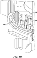
- the image capture apparatus 102 may include any conventional image capture means.
- the image capture apparatus 102 may be a video camera, a digital still camera, a line scanner, a CCD array, etc.
- the system 100 may include one or more image capture apparatuses 102.
- Conventional vision systems may capture the image as a two dimensional array.
- the image may be interpolated horizontally through a cylindrical lens. In this case, the data from the image will be present only in one dimension.
- the controller 112 may include various communications facilities including input/output ports, a keyboard, a mouse, a display, a network adapter, etc. In some embodiments, the controller 112 may be operative to execute program instructions to perform the methods of the present invention described herein.
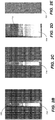
- the differential filter may be used to filter the area of interest, in the vertical dimension, to emphasize or detect the air-sample interface and bottom of the container ( FIG. 2E ).
- Any suitable differential or high pass filter or the like may be used.
- a finite impulse response (FIR) filter e.g., a Butterworth filter, a Chebyshev filter, a Bessel filter and/or an Elliptic filter may be used.
- digital filters e.g., FIR, Butterworth, Chebyshev, Bessel, and Elliptic
- FIR finite impulse response
- Butterworth filter e.g., Butterworth, Chebyshev, Bessel, and Elliptic
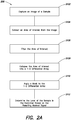
- step S202 the image capture apparatus 102 captures an image of the sample 104.
- step S204 the image may be cropped and the geometry adjusted (if necessary) to extract an area of interest from the image.
- a differential filter may be applied to the area of interest.
- the differential two dimensional array may be split or divided into "n" narrower vertical arrays.
- each of the "n" differential two dimensional arrays may be collapsed horizontally into "n” one dimensional differential array in step S210.
- the "n" two dimensional arrays may be collapsed into the "n” one dimensional array before application of the differential filter.
- Each element of the differential one dimensional array may be the normalized sum (or average) of all the line elements of the divided source (two dimensional) array.
- the differential one dimensional arrays may include noise.
- the noise may be corrected via a mask, by multiplying the differential one dimensional arrays by the result of the threshold in step S212.
- the controller 112 may employ an algorithm to separately analyze each of the resulting "n" masked differential one dimensional arrays to determine the presence of peaks in step S214.
- step S216 the resulting peaks are combined and counted (per vertical unit) to form a histogram. Then in step S218, a low pass filter and additional masks are applied to the histogram to correct for any noise.
- the resulting histogram is analyzed to determine the air/sample interface 110 in step S220. For example, two or more peaks, depending in part on the number "n," in the same vertical location may be indicative of the major interface that may be the air/sample interface 110, the foam/sample interface or the foam/air interface, after the bottom of the container 104 is excluded.
- the air/sample interface 110 is indicative of the height or level of the sample 104 in the container 106. As described above with respect to method 200 and FIG. 2A , by determining the air/sample interface 110, the algorithm may calculate the volume of sample 104 in the container 106 from the height of the sample 104 in the container 106, provided the container 106 has known dimensions.
Landscapes
- Physics & Mathematics (AREA)
- Electromagnetism (AREA)
- Fluid Mechanics (AREA)
- General Physics & Mathematics (AREA)
- Engineering & Computer Science (AREA)
- Signal Processing (AREA)
- Thermal Sciences (AREA)
- Measurement Of Levels Of Liquids Or Fluent Solid Materials (AREA)
- Investigating Or Analysing Materials By Optical Means (AREA)
- Investigating Materials By The Use Of Optical Means Adapted For Particular Applications (AREA)
- Image Processing (AREA)
- Length Measuring Devices By Optical Means (AREA)
Claims (12)
- Verfahren zum Bestimmen eines Flüssigkeitpegels einer Probe in einem Behälter, das Folgendes umfasst:a) Aufnehmen eines Bildes einer Probe, die sich in dem Behälter befindet, wobei das Bild als eine zweidimensionale Anordnung von Lichtintensitäten dargestellt wird;b) Extrahieren eines interessierenden Bereichs aus dem Bild, um eine interessierende zweidimensionale Anordnung zu erhalten;c) Verarbeiten der interessierenden zweidimensionalen Anordnung mit einem Differenzialfilter in der vertikalen Dimension, um eine differenziell gefilterte zweidimensionale Anordnung zu erhalten;d) Unterteilen der differenziell gefilterten zweidimensionalen Anordnung in "n" kleinere vertikale Anordnungen;e) horizontales Zusammenklappen der "n" zweidimensionalen vertikalen Anordnungen, um "n" eindimensionale differenzielle Anordnungen zu bilden;f) Anwenden einer Maske auf die "n" eindimensionalen differenziellen Anordnungen, um Rauschen zu erfassen;g) Analysieren jeder der sich ergebenden "n" maskierten, vertikalen eindimensionalen differenziellen Anordnungen, um das Vorhandensein von Spitzen zu bestimmen;h) Kombinieren und Zählen pro vertikaler Einheit der Spitzen, die sich aus der Analyse ergeben;i) Bilden eines Histogramms aus den kombinierten und gezählten Spitzen, um eine Häufigkeit des Auftretens von Spitzen pro vertikaler Einheit zu erhalten; undj) ferner Verarbeiten des sich ergebenden Histogramms, um den Boden des Behälters und die Grenzfläche/den Pegel der Flüssigkeit und der umgebenden Luft sowie das Vorhandensein von Schaum und/oder anderen Gegenständen zu bestimmen.
- Verfahren nach Anspruch 1, wobei das Filtern des interessierenden Bereichs eine Luft/Proben-Grenzfläche in der Probe hervorhebt.
- Verfahren nach Anspruch 1, wobei das Rauschen Schaum und/oder Staub auf der Oberfläche der Probe sowie Turbulenzen in der Probe umfasst.
- Verfahren nach Anspruch 1, wobei das Extrahieren des interessierenden Bereichs aus dem Bild ferner Folgendes umfasst: Beschneiden des Bildes.
- Verfahren nach Anspruch 1, wobei das Extrahieren des interessierenden Bereichs aus dem Bild ferner Folgendes umfasst: Einstellen der Geometrie des Bildes.
- Verfahren nach Anspruch 1, wobei das Maskieren der eindimensionalen Anordnung ferner Folgendes umfasst: Anwenden eines Schwellenwerts als eine Maske, wobei der Schwellenwert die eine eindimensionale Anordnung zuzüglich einer Konstante zu der einen eindimensionalen Anordnung enthält.
- Verfahren nach Anspruch 6, wobei das Bestimmen des Pegels der Probe in dem Behälter ferner Folgendes umfasst:
Durchsuchen des maskierten Signals auf lokale Spitzen. - Verwendung des Verfahrens nach Anspruch 1 zum Bestimmen des Vorhandenseins einer Schaummenge auf einer Oberfläche einer Probe, wobei im Schritt j) ein Bereich einer zusammenhängenden Konzentration von Spitzen in wenigstens einer Richtung weg von der Grenzfläche detektiert wird und wobei die zusammenhängende Konzentration der Schaum ist.
- Verwendung nach Anspruch 8, wobei die zusammenhängende Konzentration von Spitzen größer oder gleich einem bestimmten Wert ist.
- Verwendung nach Anspruch 9, die ferner Folgendes umfasst:
Bestimmen der Schaummenge anhand einer Breite des Bereichs der zusammenhängenden Konzentration von Spitzen und einer Höhe des Schaums. - Verwendung nach Anspruch 10, wobei die zusammenhängende Konzentration von Spitzen durch einen Abstand getrennt ist und der Abstand kleiner oder gleich einer im Voraus festgelegten Zahl ist.
- Verwendung nach Anspruch 11, wobei die im Voraus festgelegte Zahl durch eine maximale Größe von Blasen definiert ist.
Applications Claiming Priority (2)
| Application Number | Priority Date | Filing Date | Title |
|---|---|---|---|
| US14269809P | 2009-01-06 | 2009-01-06 | |
| PCT/US2009/067645 WO2010080340A1 (en) | 2009-01-06 | 2009-12-11 | Methods and apparatus for determining a liquid level in a container using imaging |
Publications (3)
| Publication Number | Publication Date |
|---|---|
| EP2373957A1 EP2373957A1 (de) | 2011-10-12 |
| EP2373957A4 EP2373957A4 (de) | 2012-07-18 |
| EP2373957B1 true EP2373957B1 (de) | 2020-04-01 |
Family
ID=42316707
Family Applications (1)
| Application Number | Title | Priority Date | Filing Date |
|---|---|---|---|
| EP09837845.8A Active EP2373957B1 (de) | 2009-01-06 | 2009-12-11 | Verfahren zur bestimmung eines flüssigkeitsstandes in einem behälter durch bilderzeugung |
Country Status (5)
| Country | Link |
|---|---|
| US (1) | US9002096B2 (de) |
| EP (1) | EP2373957B1 (de) |
| JP (1) | JP5639078B2 (de) |
| CN (1) | CN102171541B (de) |
| WO (1) | WO2010080340A1 (de) |
Families Citing this family (39)
| Publication number | Priority date | Publication date | Assignee | Title |
|---|---|---|---|---|
| EP2752670A2 (de) | 2010-07-23 | 2014-07-09 | Beckman Coulter, Inc. | System oder Verfahren zur Aufnahme analytischer Einheiten |
| KR20140036178A (ko) | 2011-05-13 | 2014-03-25 | 베크만 컬터, 인코포레이티드 | 실험실 제품 이송 요소 및 경로 배열 구조체 |
| WO2012158541A1 (en) | 2011-05-13 | 2012-11-22 | Beckman Coulter, Inc. | System and method including laboratory product transport element |
| CN202236824U (zh) * | 2011-08-29 | 2012-05-30 | 惠州市华阳医疗电子有限公司 | 具有渗出液流速报警功能的负压伤口治疗系统 |
| TWI708052B (zh) | 2011-08-29 | 2020-10-21 | 美商安美基公司 | 用於非破壞性檢測-流體中未溶解粒子之方法及裝置 |
| ES2844324T3 (es) | 2011-11-07 | 2021-07-21 | Beckman Coulter Inc | Brazo robótico |
| EP2776846B1 (de) | 2011-11-07 | 2019-08-21 | Beckman Coulter, Inc. | Aliquotierungssystem und arbeitsablauf |
| US9046506B2 (en) | 2011-11-07 | 2015-06-02 | Beckman Coulter, Inc. | Specimen container detection |
| US8973736B2 (en) | 2011-11-07 | 2015-03-10 | Beckman Coulter, Inc. | Magnetic damping for specimen transport system |
| CN104053997B (zh) | 2011-11-07 | 2016-12-21 | 贝克曼考尔特公司 | 用于处理样本的系统和方法 |
| BR112014011046A2 (pt) | 2011-11-07 | 2017-06-13 | Beckman Coulter, Inc. | fluxo de trabalho e sistema de centrífuga |
| CN102519540A (zh) * | 2011-12-10 | 2012-06-27 | 山东明佳包装检测科技有限公司 | 一种啤酒泡沫补偿液位的检测方法 |
| JP5861008B2 (ja) | 2012-09-14 | 2016-02-16 | ベックマン コールター, インコーポレイテッド | キャピラリ輸送体を備える分析システム |
| US9927450B2 (en) | 2013-03-08 | 2018-03-27 | Siemens Healthcare Diagnostics Inc. | Tube characterization station |
| NO336180B1 (no) * | 2013-04-04 | 2015-06-08 | Univisual Instr | System og fremgangsmåte for å bestemme fluidnivåer |
| US9459130B2 (en) | 2013-11-13 | 2016-10-04 | Deere & Company | System for measuring a liquid level and orientation |
| US9528871B2 (en) | 2013-11-13 | 2016-12-27 | Deere & Company | System for determining a liquid quantity and orientation |
| US9576355B2 (en) * | 2014-01-31 | 2017-02-21 | Catamaran Corporation | System and method of monitoring and confirming medication dosage |
| CN104316709B (zh) * | 2014-10-15 | 2016-03-30 | 中国航空工业集团公司北京航空材料研究院 | 一种用于实现容量瓶定容的自动加液控制方法 |
| WO2016187072A1 (en) | 2015-05-15 | 2016-11-24 | Gauss Surgical, Inc. | Methods and systems for characterizing fluids from a patient |
| CN105488788B (zh) * | 2015-11-24 | 2019-04-05 | 大连楼兰科技股份有限公司 | 汽车液体余量检测方法 |
| AU2017269412B2 (en) * | 2016-05-27 | 2022-01-20 | Biomerieux, Inc. | Method and apparatus for detection of foam in specimen containers |
| DE102016209756A1 (de) * | 2016-06-03 | 2017-12-07 | Voith Patent Gmbh | Ermittlung eines Füllstandes bei einer hydrodynamischen Kupplung |
| GB201614717D0 (en) * | 2016-08-31 | 2016-10-12 | Ge Healthcare Bio Sciences Ab | Detection of foam levels |
| BR112019008270A8 (pt) | 2016-10-28 | 2023-04-11 | Beckman Coulter Inc | Sistema de avaliação de preparação de substância |
| US10088660B2 (en) | 2017-02-10 | 2018-10-02 | Amgen Inc. | Imaging system for counting and sizing particles in fluid-filled vessels |
| JP6729971B2 (ja) * | 2017-08-30 | 2020-07-29 | 三菱電機株式会社 | 水位計測装置および水際線抽出方法 |
| CN109544500A (zh) * | 2017-09-20 | 2019-03-29 | 诚锋兴业股份有限公司 | 鞋面组装操作的辨识装置及辨识方法 |
| CN109029618B (zh) * | 2018-07-11 | 2020-02-07 | 苏州科技大学 | 单目视觉包装箱体积测量方法 |
| ES3030112T3 (en) | 2018-08-22 | 2025-06-26 | Bio Merieux Inc | Detection instruments with automated cell location selection for newly intaken specimen containers and related methods |
| JP7185475B2 (ja) * | 2018-10-11 | 2022-12-07 | 株式会社Subaru | シール剤吐出装置 |
| WO2020117780A1 (en) | 2018-12-03 | 2020-06-11 | Bio-Rad Laboratories, Inc. | Liquid level determination |
| EP3835737B1 (de) * | 2019-12-10 | 2024-03-20 | Roche Diagnostics GmbH | Verfahren und vorrichtung zur bestimmung einer vertikalen position einer horizontal verlängerten schnittstelle zwischen einer ersten komponente und einer zweiten komponente |
| FR3111697A1 (fr) | 2020-06-18 | 2021-12-24 | Ceva Sante Animale | Système de détection d’un état de remplissage d’un flacon d’un diffuseur |
| US11681984B2 (en) | 2020-08-20 | 2023-06-20 | Scaled Solutions Technologies LLC | Inventory management systems and related methods |
| CN112324893B (zh) * | 2020-10-30 | 2022-10-11 | 重庆长安汽车股份有限公司 | 一种自动变速器油位监测系统及监测方法 |
| GB2612037A (en) * | 2021-10-19 | 2023-04-26 | Stanhope Seta Ltd | Analytical apparatus |
| US11674839B1 (en) * | 2022-02-03 | 2023-06-13 | Plainsight Corp. | System and method of detecting fluid levels in tanks |
| CN117268498B (zh) * | 2023-11-20 | 2024-01-23 | 中国航空工业集团公司金城南京机电液压工程研究中心 | 一种油量测量方法及系统 |
Family Cites Families (47)
| Publication number | Priority date | Publication date | Assignee | Title |
|---|---|---|---|---|
| JPS59180313A (ja) * | 1983-03-30 | 1984-10-13 | Toshiba Corp | 表面検査装置 |
| JPS60104205A (ja) * | 1983-11-10 | 1985-06-08 | Nippon Denso Co Ltd | 噴射体の形状測定方法及びその装置 |
| US4998285A (en) * | 1988-03-11 | 1991-03-05 | Kabushiki Kaisha Toshiba | Character recognition apparatus |
| JP2647504B2 (ja) | 1989-07-26 | 1997-08-27 | オリンパス光学工業株式会社 | 実像式変倍ファインダー |
| JPH0359411A (ja) * | 1989-07-27 | 1991-03-14 | Nec Corp | 液量計測装置 |
| EP0416607B1 (de) * | 1989-09-08 | 1994-12-21 | Kabushiki Kaisha Kirin Techno System | Verfahren und Gerät zum Nachweisen von Fremdkörpern |
| EP0472313B1 (de) * | 1990-08-03 | 1998-11-11 | Canon Kabushiki Kaisha | Gerät und Verfahren zur Bildverarbeitung |
| US5204911A (en) * | 1991-05-29 | 1993-04-20 | Nira Schwartz | Inspection method using unique templates and histogram analysis |
| US5321770A (en) * | 1991-11-19 | 1994-06-14 | Xerox Corporation | Method for determining boundaries of words in text |
| US5542004A (en) * | 1991-11-25 | 1996-07-30 | Miller Brewing Company | Foam analyzing method and apparatus |
| DE4314249A1 (de) * | 1993-04-30 | 1994-11-03 | Maz Mikroelektronik Anwendungs | Vorrichtung zur Erfassung des Flüssigkeitspegels |
| US5414778A (en) * | 1993-11-24 | 1995-05-09 | Schwartz; Nira | Dynamic fluid level and bubble inspection for quality and process control |
| US6252980B1 (en) * | 1993-11-24 | 2001-06-26 | Nira Schwartz | Additional dynamic fluid level and bubble inspection for quality and process control |
| US6098029A (en) * | 1994-06-14 | 2000-08-01 | Hitachi, Ltd. | Liquid-level position measuring method and system |
| EP0699889A3 (de) * | 1994-08-24 | 1996-12-04 | Eastman Kodak Co | Apparat und Verfahren zur Messung eines Spaltes |
| US5845002A (en) * | 1994-11-03 | 1998-12-01 | Sunkist Growers, Inc. | Method and apparatus for detecting surface features of translucent objects |
| JP3805005B2 (ja) * | 1994-11-09 | 2006-08-02 | キヤノン株式会社 | 画像処理装置及び光学的文字認識装置及びそれらの方法 |
| JPH08278186A (ja) * | 1995-04-07 | 1996-10-22 | Central Japan Railway Co | 液面検出方法及び液面検出装置 |
| US5889884A (en) * | 1995-05-23 | 1999-03-30 | Minolta Co., Ltd. | Image forming apparatus capable of recognizing top and bottom of document image |
| US5781665A (en) * | 1995-08-28 | 1998-07-14 | Pitney Bowes Inc. | Apparatus and method for cropping an image |
| GB9521285D0 (en) * | 1995-10-18 | 1995-12-20 | Pa Consulting Services | Improvements in or relating to detection of foreign objects in fluid |
| CA2270898A1 (en) | 1996-11-06 | 1998-05-14 | The Regents Of The University Of California | Isolated tumor necrosis factor receptor releasing enzyme, compositions comprising the enzyme and methods of the use thereof |
| US6683783B1 (en) * | 1997-03-07 | 2004-01-27 | William Marsh Rice University | Carbon fibers formed from single-wall carbon nanotubes |
| US6226081B1 (en) * | 1997-03-24 | 2001-05-01 | Optikos Corporation | Optical height of fill detection system and associated methods |
| US6049379A (en) * | 1997-12-30 | 2000-04-11 | Coors Brewing Company | Method for inspecting translucent objects using imaging techniques |
| US6249602B1 (en) * | 1998-05-28 | 2001-06-19 | Cognex Corporation | Method and apparatus for determining a reference point of an object profile within an image |
| GB2341231A (en) * | 1998-09-05 | 2000-03-08 | Sharp Kk | Face detection in an image |
| CA2403094C (en) | 2000-03-17 | 2011-07-12 | Zograph, Llc | High acuity lens system |
| US6782122B1 (en) * | 2000-04-27 | 2004-08-24 | Simmonds Precision Products, Inc. | Apparatus for measuring height of a liquid in a container using area image pattern recognition techniques |
| US6909805B2 (en) * | 2001-01-31 | 2005-06-21 | Matsushita Electric Industrial Co., Ltd. | Detecting and utilizing add-on information from a scanned document image |
| JP3468755B2 (ja) * | 2001-03-05 | 2003-11-17 | 石川島播磨重工業株式会社 | 液晶駆動基板の検査装置 |
| WO2003060433A2 (de) | 2002-01-16 | 2003-07-24 | Peter Holubar | Verfahren zur erfassung der lage grenzfläche zwischen zwei medien |
| WO2003104748A1 (de) * | 2002-06-07 | 2003-12-18 | Leica Geosystem Ag | Optischer neigungsmesser |
| US7133572B2 (en) * | 2002-10-02 | 2006-11-07 | Siemens Corporate Research, Inc. | Fast two dimensional object localization based on oriented edges |
| CN2588336Y (zh) * | 2002-12-17 | 2003-11-26 | 深圳市纽吉特电子技术有限公司 | 光学成像式液面测量装置 |
| US7522762B2 (en) * | 2003-04-16 | 2009-04-21 | Inverness Medical-Biostar, Inc. | Detection, resolution, and identification of arrayed elements |
| ATE476908T1 (de) * | 2003-04-18 | 2010-08-15 | Medispectra Inc | System und diagnoseverfahren zur optischen detektion von verdächtigen stellen einer gewebeprobe |
| US7536032B2 (en) * | 2003-10-24 | 2009-05-19 | Reactrix Systems, Inc. | Method and system for processing captured image information in an interactive video display system |
| US7049622B1 (en) * | 2004-04-09 | 2006-05-23 | Sandia Corporation | Optical position sensor for determining the interface between a clear and an opaque fluid |
| JP4517826B2 (ja) * | 2004-11-15 | 2010-08-04 | パナソニック電工株式会社 | 液面検出方法 |
| ATE466278T1 (de) * | 2005-10-15 | 2010-05-15 | Udviklingsselskabet Innoscan K | Verfahren und system zur bestrahlung und inspektion flüssigkeitstragender behälter |
| US7840360B1 (en) * | 2006-10-26 | 2010-11-23 | Micheels Ronald H | Optical system and method for inspection and characterization of liquids in vessels |
| CN100436658C (zh) * | 2006-12-28 | 2008-11-26 | 西安理工大学 | 直拉法单晶硅生长过程中的熔体液面位置检测方法 |
| JP5246531B2 (ja) * | 2007-04-11 | 2013-07-24 | 澁谷工業株式会社 | 液面高さの測定方法 |
| US8600135B2 (en) * | 2007-06-28 | 2013-12-03 | Mayo Foundation For Medical Education And Research | System and method for automatically generating sample points from a series of medical images and identifying a significant region |
| US10197505B2 (en) * | 2007-08-22 | 2019-02-05 | Camtek Ltd. | Method and system for low cost inspection |
| US8184848B2 (en) * | 2009-06-17 | 2012-05-22 | National Applied Research Laboratories | Liquid level detection method |
-
2009
- 2009-12-11 EP EP09837845.8A patent/EP2373957B1/de active Active
- 2009-12-11 CN CN2009801388952A patent/CN102171541B/zh active Active
- 2009-12-11 US US13/143,353 patent/US9002096B2/en active Active
- 2009-12-11 WO PCT/US2009/067645 patent/WO2010080340A1/en not_active Ceased
- 2009-12-11 JP JP2011545359A patent/JP5639078B2/ja active Active
Non-Patent Citations (1)
| Title |
|---|
| None * |
Also Published As
| Publication number | Publication date |
|---|---|
| WO2010080340A1 (en) | 2010-07-15 |
| US9002096B2 (en) | 2015-04-07 |
| EP2373957A1 (de) | 2011-10-12 |
| CN102171541B (zh) | 2013-03-27 |
| CN102171541A (zh) | 2011-08-31 |
| JP5639078B2 (ja) | 2014-12-10 |
| US20110268329A1 (en) | 2011-11-03 |
| JP2012514751A (ja) | 2012-06-28 |
| EP2373957A4 (de) | 2012-07-18 |
Similar Documents
| Publication | Publication Date | Title |
|---|---|---|
| EP2373957B1 (de) | Verfahren zur bestimmung eines flüssigkeitsstandes in einem behälter durch bilderzeugung | |
| US8452046B2 (en) | Method and apparatus for automatic sediment or sludge detection, monitoring, and inspection in oil storage and other facilities | |
| AU725820B2 (en) | Method and apparatus for assessing slide and specimen preparation quality | |
| JP4765890B2 (ja) | 異物検出装置 | |
| EP2112514A1 (de) | Verfahren und Vorrichtung zur Überprüfung der Flüssigkeit in einer Pipettenspitze | |
| JPH0475463B2 (de) | ||
| US9092650B2 (en) | Methods and apparatus for automated detection of the presence and type of caps on vials and containers | |
| WO2023035544A1 (zh) | 一种基于视觉边缘检测的实验室空间波浪实时测量方法 | |
| CN111896549A (zh) | 一种基于机器学习的建筑物裂缝监测系统和方法 | |
| CN102481117A (zh) | 用于探测在三维重建中的不良质量的系统和方法 | |
| CN102323281B (zh) | 液体性质检测方法和系统 | |
| CN119915825A (zh) | 一种基于Mueller矩阵探测的金属表面缺陷检测装置及方法 | |
| JP2019521353A (ja) | 臨床分析器における吸引不足の検出 | |
| Forbes et al. | Estimating fruit volume from digital images | |
| CN114152557A (zh) | 基于图像分析的血细胞计数方法和系统 | |
| CN117705754B (zh) | 一种基于高光谱成像的纺织品聚酯纤维含量在线检测方法 | |
| CN116794031A (zh) | 一种振荡型密度计液体样品中气泡的检测方法 | |
| JP2008304958A (ja) | 画像処理によるワーク欠陥検査方法 | |
| Noelle et al. | Calibrated bubble depth determination using a single camera | |
| JP3297945B2 (ja) | 鋼板表面欠陥検出方法 | |
| Chen et al. | Research on Verification Techniques of Common Glass Measuring Capacity Based on Image Processing | |
| JPH04238207A (ja) | 欠陥検査装置 | |
| TW389830B (en) | Method for analyzing weft characteristics by applying digital image processes | |
| CN116265866A (zh) | 基于机器视觉的活塞式离心筒内体积检测方法及装置 | |
| RU2471175C1 (ru) | Способ определения мутности среды |
Legal Events
| Date | Code | Title | Description |
|---|---|---|---|
| PUAI | Public reference made under article 153(3) epc to a published international application that has entered the european phase |
Free format text: ORIGINAL CODE: 0009012 |
|
| 17P | Request for examination filed |
Effective date: 20110519 |
|
| AK | Designated contracting states |
Kind code of ref document: A1 Designated state(s): AT BE BG CH CY CZ DE DK EE ES FI FR GB GR HR HU IE IS IT LI LT LU LV MC MK MT NL NO PL PT RO SE SI SK SM TR |
|
| DAX | Request for extension of the european patent (deleted) | ||
| A4 | Supplementary search report drawn up and despatched |
Effective date: 20120618 |
|
| RIC1 | Information provided on ipc code assigned before grant |
Ipc: G01F 23/292 20060101AFI20120612BHEP Ipc: G01F 23/00 20060101ALI20120612BHEP |
|
| STAA | Information on the status of an ep patent application or granted ep patent |
Free format text: STATUS: EXAMINATION IS IN PROGRESS |
|
| 17Q | First examination report despatched |
Effective date: 20171211 |
|
| RAP1 | Party data changed (applicant data changed or rights of an application transferred) |
Owner name: SIEMENS HEALTHCARE DIAGNOSTICS INC. |
|
| GRAP | Despatch of communication of intention to grant a patent |
Free format text: ORIGINAL CODE: EPIDOSNIGR1 |
|
| STAA | Information on the status of an ep patent application or granted ep patent |
Free format text: STATUS: GRANT OF PATENT IS INTENDED |
|
| INTG | Intention to grant announced |
Effective date: 20191025 |
|
| GRAS | Grant fee paid |
Free format text: ORIGINAL CODE: EPIDOSNIGR3 |
|
| GRAA | (expected) grant |
Free format text: ORIGINAL CODE: 0009210 |
|
| STAA | Information on the status of an ep patent application or granted ep patent |
Free format text: STATUS: THE PATENT HAS BEEN GRANTED |
|
| AK | Designated contracting states |
Kind code of ref document: B1 Designated state(s): AT BE BG CH CY CZ DE DK EE ES FI FR GB GR HR HU IE IS IT LI LT LU LV MC MK MT NL NO PL PT RO SE SI SK SM TR |
|
| REG | Reference to a national code |
Ref country code: GB Ref legal event code: FG4D |
|
| REG | Reference to a national code |
Ref country code: AT Ref legal event code: REF Ref document number: 1251961 Country of ref document: AT Kind code of ref document: T Effective date: 20200415 Ref country code: CH Ref legal event code: EP |
|
| REG | Reference to a national code |
Ref country code: DE Ref legal event code: R096 Ref document number: 602009061621 Country of ref document: DE |
|
| REG | Reference to a national code |
Ref country code: IE Ref legal event code: FG4D |
|
| PG25 | Lapsed in a contracting state [announced via postgrant information from national office to epo] |
Ref country code: BG Free format text: LAPSE BECAUSE OF FAILURE TO SUBMIT A TRANSLATION OF THE DESCRIPTION OR TO PAY THE FEE WITHIN THE PRESCRIBED TIME-LIMIT Effective date: 20200701 |
|
| REG | Reference to a national code |
Ref country code: NL Ref legal event code: MP Effective date: 20200401 |
|
| REG | Reference to a national code |
Ref country code: LT Ref legal event code: MG4D |
|
| PG25 | Lapsed in a contracting state [announced via postgrant information from national office to epo] |
Ref country code: CZ Free format text: LAPSE BECAUSE OF FAILURE TO SUBMIT A TRANSLATION OF THE DESCRIPTION OR TO PAY THE FEE WITHIN THE PRESCRIBED TIME-LIMIT Effective date: 20200401 Ref country code: NL Free format text: LAPSE BECAUSE OF FAILURE TO SUBMIT A TRANSLATION OF THE DESCRIPTION OR TO PAY THE FEE WITHIN THE PRESCRIBED TIME-LIMIT Effective date: 20200401 Ref country code: NO Free format text: LAPSE BECAUSE OF FAILURE TO SUBMIT A TRANSLATION OF THE DESCRIPTION OR TO PAY THE FEE WITHIN THE PRESCRIBED TIME-LIMIT Effective date: 20200701 Ref country code: IS Free format text: LAPSE BECAUSE OF FAILURE TO SUBMIT A TRANSLATION OF THE DESCRIPTION OR TO PAY THE FEE WITHIN THE PRESCRIBED TIME-LIMIT Effective date: 20200801 Ref country code: SE Free format text: LAPSE BECAUSE OF FAILURE TO SUBMIT A TRANSLATION OF THE DESCRIPTION OR TO PAY THE FEE WITHIN THE PRESCRIBED TIME-LIMIT Effective date: 20200401 Ref country code: FI Free format text: LAPSE BECAUSE OF FAILURE TO SUBMIT A TRANSLATION OF THE DESCRIPTION OR TO PAY THE FEE WITHIN THE PRESCRIBED TIME-LIMIT Effective date: 20200401 Ref country code: GR Free format text: LAPSE BECAUSE OF FAILURE TO SUBMIT A TRANSLATION OF THE DESCRIPTION OR TO PAY THE FEE WITHIN THE PRESCRIBED TIME-LIMIT Effective date: 20200702 Ref country code: LT Free format text: LAPSE BECAUSE OF FAILURE TO SUBMIT A TRANSLATION OF THE DESCRIPTION OR TO PAY THE FEE WITHIN THE PRESCRIBED TIME-LIMIT Effective date: 20200401 Ref country code: PT Free format text: LAPSE BECAUSE OF FAILURE TO SUBMIT A TRANSLATION OF THE DESCRIPTION OR TO PAY THE FEE WITHIN THE PRESCRIBED TIME-LIMIT Effective date: 20200817 |
|
| REG | Reference to a national code |
Ref country code: AT Ref legal event code: MK05 Ref document number: 1251961 Country of ref document: AT Kind code of ref document: T Effective date: 20200401 |
|
| PG25 | Lapsed in a contracting state [announced via postgrant information from national office to epo] |
Ref country code: LV Free format text: LAPSE BECAUSE OF FAILURE TO SUBMIT A TRANSLATION OF THE DESCRIPTION OR TO PAY THE FEE WITHIN THE PRESCRIBED TIME-LIMIT Effective date: 20200401 Ref country code: HR Free format text: LAPSE BECAUSE OF FAILURE TO SUBMIT A TRANSLATION OF THE DESCRIPTION OR TO PAY THE FEE WITHIN THE PRESCRIBED TIME-LIMIT Effective date: 20200401 |
|
| REG | Reference to a national code |
Ref country code: DE Ref legal event code: R097 Ref document number: 602009061621 Country of ref document: DE |
|
| PG25 | Lapsed in a contracting state [announced via postgrant information from national office to epo] |
Ref country code: ES Free format text: LAPSE BECAUSE OF FAILURE TO SUBMIT A TRANSLATION OF THE DESCRIPTION OR TO PAY THE FEE WITHIN THE PRESCRIBED TIME-LIMIT Effective date: 20200401 Ref country code: AT Free format text: LAPSE BECAUSE OF FAILURE TO SUBMIT A TRANSLATION OF THE DESCRIPTION OR TO PAY THE FEE WITHIN THE PRESCRIBED TIME-LIMIT Effective date: 20200401 Ref country code: RO Free format text: LAPSE BECAUSE OF FAILURE TO SUBMIT A TRANSLATION OF THE DESCRIPTION OR TO PAY THE FEE WITHIN THE PRESCRIBED TIME-LIMIT Effective date: 20200401 Ref country code: SM Free format text: LAPSE BECAUSE OF FAILURE TO SUBMIT A TRANSLATION OF THE DESCRIPTION OR TO PAY THE FEE WITHIN THE PRESCRIBED TIME-LIMIT Effective date: 20200401 Ref country code: EE Free format text: LAPSE BECAUSE OF FAILURE TO SUBMIT A TRANSLATION OF THE DESCRIPTION OR TO PAY THE FEE WITHIN THE PRESCRIBED TIME-LIMIT Effective date: 20200401 Ref country code: DK Free format text: LAPSE BECAUSE OF FAILURE TO SUBMIT A TRANSLATION OF THE DESCRIPTION OR TO PAY THE FEE WITHIN THE PRESCRIBED TIME-LIMIT Effective date: 20200401 Ref country code: IT Free format text: LAPSE BECAUSE OF FAILURE TO SUBMIT A TRANSLATION OF THE DESCRIPTION OR TO PAY THE FEE WITHIN THE PRESCRIBED TIME-LIMIT Effective date: 20200401 |
|
| PLBE | No opposition filed within time limit |
Free format text: ORIGINAL CODE: 0009261 |
|
| STAA | Information on the status of an ep patent application or granted ep patent |
Free format text: STATUS: NO OPPOSITION FILED WITHIN TIME LIMIT |
|
| PG25 | Lapsed in a contracting state [announced via postgrant information from national office to epo] |
Ref country code: SK Free format text: LAPSE BECAUSE OF FAILURE TO SUBMIT A TRANSLATION OF THE DESCRIPTION OR TO PAY THE FEE WITHIN THE PRESCRIBED TIME-LIMIT Effective date: 20200401 Ref country code: PL Free format text: LAPSE BECAUSE OF FAILURE TO SUBMIT A TRANSLATION OF THE DESCRIPTION OR TO PAY THE FEE WITHIN THE PRESCRIBED TIME-LIMIT Effective date: 20200401 |
|
| 26N | No opposition filed |
Effective date: 20210112 |
|
| PG25 | Lapsed in a contracting state [announced via postgrant information from national office to epo] |
Ref country code: SI Free format text: LAPSE BECAUSE OF FAILURE TO SUBMIT A TRANSLATION OF THE DESCRIPTION OR TO PAY THE FEE WITHIN THE PRESCRIBED TIME-LIMIT Effective date: 20200401 |
|
| REG | Reference to a national code |
Ref country code: CH Ref legal event code: PL |
|
| GBPC | Gb: european patent ceased through non-payment of renewal fee |
Effective date: 20201211 |
|
| PG25 | Lapsed in a contracting state [announced via postgrant information from national office to epo] |
Ref country code: MC Free format text: LAPSE BECAUSE OF FAILURE TO SUBMIT A TRANSLATION OF THE DESCRIPTION OR TO PAY THE FEE WITHIN THE PRESCRIBED TIME-LIMIT Effective date: 20200401 |
|
| REG | Reference to a national code |
Ref country code: BE Ref legal event code: MM Effective date: 20201231 |
|
| PG25 | Lapsed in a contracting state [announced via postgrant information from national office to epo] |
Ref country code: IE Free format text: LAPSE BECAUSE OF NON-PAYMENT OF DUE FEES Effective date: 20201211 Ref country code: LU Free format text: LAPSE BECAUSE OF NON-PAYMENT OF DUE FEES Effective date: 20201211 Ref country code: FR Free format text: LAPSE BECAUSE OF NON-PAYMENT OF DUE FEES Effective date: 20201231 |
|
| PG25 | Lapsed in a contracting state [announced via postgrant information from national office to epo] |
Ref country code: LI Free format text: LAPSE BECAUSE OF NON-PAYMENT OF DUE FEES Effective date: 20201231 Ref country code: GB Free format text: LAPSE BECAUSE OF NON-PAYMENT OF DUE FEES Effective date: 20201211 Ref country code: CH Free format text: LAPSE BECAUSE OF NON-PAYMENT OF DUE FEES Effective date: 20201231 |
|
| PG25 | Lapsed in a contracting state [announced via postgrant information from national office to epo] |
Ref country code: TR Free format text: LAPSE BECAUSE OF FAILURE TO SUBMIT A TRANSLATION OF THE DESCRIPTION OR TO PAY THE FEE WITHIN THE PRESCRIBED TIME-LIMIT Effective date: 20200401 Ref country code: MT Free format text: LAPSE BECAUSE OF FAILURE TO SUBMIT A TRANSLATION OF THE DESCRIPTION OR TO PAY THE FEE WITHIN THE PRESCRIBED TIME-LIMIT Effective date: 20200401 Ref country code: CY Free format text: LAPSE BECAUSE OF FAILURE TO SUBMIT A TRANSLATION OF THE DESCRIPTION OR TO PAY THE FEE WITHIN THE PRESCRIBED TIME-LIMIT Effective date: 20200401 |
|
| PG25 | Lapsed in a contracting state [announced via postgrant information from national office to epo] |
Ref country code: MK Free format text: LAPSE BECAUSE OF FAILURE TO SUBMIT A TRANSLATION OF THE DESCRIPTION OR TO PAY THE FEE WITHIN THE PRESCRIBED TIME-LIMIT Effective date: 20200401 |
|
| PG25 | Lapsed in a contracting state [announced via postgrant information from national office to epo] |
Ref country code: BE Free format text: LAPSE BECAUSE OF NON-PAYMENT OF DUE FEES Effective date: 20201231 |
|
| PGFP | Annual fee paid to national office [announced via postgrant information from national office to epo] |
Ref country code: DE Payment date: 20250220 Year of fee payment: 16 |
|
| REG | Reference to a national code |
Ref country code: DE Ref legal event code: R082 Ref document number: 602009061621 Country of ref document: DE |
|
| PG25 | Lapsed in a contracting state [announced via postgrant information from national office to epo] |
Ref country code: IS Free format text: LAPSE BECAUSE OF NON-PAYMENT OF DUE FEES Effective date: 20200801 |