EP2372042A2 - Système de plinthe - Google Patents
Système de plinthe Download PDFInfo
- Publication number
- EP2372042A2 EP2372042A2 EP11159950A EP11159950A EP2372042A2 EP 2372042 A2 EP2372042 A2 EP 2372042A2 EP 11159950 A EP11159950 A EP 11159950A EP 11159950 A EP11159950 A EP 11159950A EP 2372042 A2 EP2372042 A2 EP 2372042A2
- Authority
- EP
- European Patent Office
- Prior art keywords
- skirting board
- wall
- baseboard
- board system
- edge
- Prior art date
- Legal status (The legal status is an assumption and is not a legal conclusion. Google has not performed a legal analysis and makes no representation as to the accuracy of the status listed.)
- Withdrawn
Links
Images
Classifications
-
- E—FIXED CONSTRUCTIONS
- E04—BUILDING
- E04F—FINISHING WORK ON BUILDINGS, e.g. STAIRS, FLOORS
- E04F19/00—Other details of constructional parts for finishing work on buildings
- E04F19/02—Borders; Finishing strips, e.g. beadings; Light coves
- E04F19/04—Borders; Finishing strips, e.g. beadings; Light coves for use between floor or ceiling and wall, e.g. skirtings
- E04F19/0459—Borders; Finishing strips, e.g. beadings; Light coves for use between floor or ceiling and wall, e.g. skirtings characterised by the fixing method
- E04F19/0463—Plinths fixed by snap-action in a direction perpendicular to the wall
-
- E—FIXED CONSTRUCTIONS
- E04—BUILDING
- E04F—FINISHING WORK ON BUILDINGS, e.g. STAIRS, FLOORS
- E04F19/00—Other details of constructional parts for finishing work on buildings
- E04F19/02—Borders; Finishing strips, e.g. beadings; Light coves
- E04F19/04—Borders; Finishing strips, e.g. beadings; Light coves for use between floor or ceiling and wall, e.g. skirtings
- E04F2019/0404—Borders; Finishing strips, e.g. beadings; Light coves for use between floor or ceiling and wall, e.g. skirtings characterised by the material
- E04F2019/0422—Borders; Finishing strips, e.g. beadings; Light coves for use between floor or ceiling and wall, e.g. skirtings characterised by the material of organic plastics with or without reinforcements or filling materials
- E04F2019/0427—Borders; Finishing strips, e.g. beadings; Light coves for use between floor or ceiling and wall, e.g. skirtings characterised by the material of organic plastics with or without reinforcements or filling materials with a integrally formed hinge
Definitions
- the invention relates to a skirting board system with a skirting board, at the rear side a first latching device is arranged, as well as with retaining clips which are fastened to the wall and have second latching devices which latch during assembly with the latching device of the skirting board.
- baseboards are mainly attached, which can cover more or less large edge joints by their cross-section or their shape and strength.
- fastening systems are used that are as invisible as possible on the front of the baseboard.
- Halteclipse which are screwed at intervals of 30 cm to 80 cm to the wall, after which then the baseboards are clipped with at least one provided on the back holding.
- a fastening element for a strip in particular a skirting board known, in which a substantially U-shaped retaining element engages in a continuous, longitudinally extending groove on the back of the bar and claws barbed on the Nutr selectedn or groove walls.
- a substantially U-shaped retaining element engages in a continuous, longitudinally extending groove on the back of the bar and claws barbed on the Nutr selectedn or groove walls.
- Different distances to the wall can be set with a spacer in the wall screw connection.
- a device for covering an inner edge of a room wherein a holding element is described, which is supported with a foot part on the ground and on a wall leg two terminal strips as the first latching device, in corresponding, parallel grooves on the back of the cover strip as a second latching device engage.
- a disadvantage of the known systems is the low flexibility in different application situations and the increased manipulation effort at different edge joint strengths.
- the object of the invention is to further develop a baseboard system such that it can be adapted in a simple manner to different edge joint widths, at the same time the visual appearance should meet the high demands in this area.
- the locking means of the retaining clips and the locking device on the back of the baseboard having a first engagement position in which a first abutment edge of the baseboard on the bottom side and a second abutment edge comes to rest on the wall, and that in a second engagement position of the locking devices the skirting board can be used turned by 180 °, wherein the first abutment edge of the skirting board comes to rest on the wall side and a second abutment edge on the bottom side.
- the latching means of the retaining clips at least one terminal block and the latching device of the skirting board one or more, preferably two parallel guided longitudinal grooves which are arranged symmetrically with respect to the two abutment edges of the baseboard and with respect to one of the two Investment edge spanned center plane have substantially vertically aligned side surfaces.
- Both variants of the invention allow easy installation of the baseboard in two engagement positions of the locking devices, the baseboard can be used rotated by 180 °.
- the retaining clip consists of a wall leg and one of them angled fortragenden necessarilyschenkel, wherein on the side facing away from the predominantlyschenkel edge of the wall leg a hinged and / or tear-off distance compensation element is attached.
- the retaining clip is preferably made of plastic, wherein the distance compensation element is integrally formed or coextruded to form a Materialengstelle or a film hinge.
- the compensating element can be demolished by the fitter, with the wall leg of the retaining clip being screwed directly to the wall.
- the distance compensation element is folded over at the film hinge and comes to rest on the back of the wall leg, whereby a wider edge joint can be bridged.
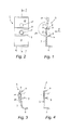
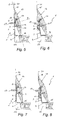
- a baseboard system 1 (see Fig. 5 to Fig. 8 ) has a wall leg 3 and one of them at an angle of about 95 ° to 105 ° projecting foot leg 4.
- the wall leg 3 is provided with a fastening opening 5 for wall mounting, for example by dowel screws 17, and with two parallel terminal strips 6, 7 (locking device of the retaining clips), which are provided with locking elements 8 for better anchoring in the parallel longitudinal grooves 13 of the baseboard 12 ,
- the groove arrangement on the back of the baseboard 12 is to be regarded as a latching device of the baseboard, which is locked during assembly with the latching device of the retaining clips (2).
- a distance compensation element 10 is integrally formed or integrally formed by injection molding or extrusion, which folded according to arrow 18 (s. Fig. 1 and Fig. 3 ) or can be removed by tearing before assembly (s. Fig. 4 ).
- the wall leg 3 has a mounting opening 5, which is aligned after folding the distance compensation element 10 with a mounting opening 11 in the spacer compensation element 10 (s. Fig. 3 ).
- the distance compensation element 10 can be torn off, since the leg 4 bridges the edge joint 22.
- the baseboard 12 has in the example shown at the back of two parallel guided longitudinal grooves 13 which are arranged symmetrically with respect to a first abutment edge 14 (bottom side) and a second abutment edge 15 (wall side) of the skirting 12 and with respect to one of the two Have abutment edges 14, 15 spanned center plane ⁇ substantially vertically oriented side surfaces 16.
- the skirting board 12 without having to make changes or adaptations, and 180 ° rotated on the terminal strips 6, 7 are plugged, so that then the first contact edge 14 wall side and the second contact edge 15 is arranged on the bottom side, as in Fig. 7 shown.
- the contour of the visible side of the baseboard 12 with respect to a lying between the first and the second abutment edge 14, 15 dividing plane ⁇ be asymmetric.
- the two parts of the visible side can also have different contours, colors, coatings or veneer jobs to achieve different effects.
- a relatively wide bottom edge joint 22 is bridged by folding over the distance compensation element 10.
- the cross section of the distance compensation element 10 is wedge-shaped, whereby not only the wall distance but also the angle between the wall leg 3 and the wall 20 changes.
- a Skirting 12 are used with the same dimensions, with both abutment edges 14, 15 optimally invest in the wall or the floor.
- FIG. 8 one with Fig. 6 comparable installation situation in which in turn the baseboard 12 was used rotated by 180 °, wherein the first contact edge 14 on the wall side and the second contact edge 15 comes to rest on the bottom side.
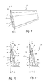
- Fig. 9 shows a variant of the skirting 12 for a retaining clip 2 according to Fig. 1 with an alternative side facing the skirting board according to Fig. 5 to Fig. 8 differs, but with compatible design of the back with the longitudinal grooves 13th
- the skirting board system according to the invention of the first embodiment variant is characterized in particular by the fact that four different installation situations can be handled with the same elements without any effort, wherein differently wide floor edge joints 22 can be bridged.
- FIG. 11 a second embodiment of the baseboard system according to the invention is shown, which is suitable to be rotated by 180 ° and to bridge different width bottom edge joints 22.
- the bottom-side abutment edge 14 or 15 of the baseboard 12 then have different distances X and Y to the wall 20 on.
- the retaining clips 2 are designed simpler and have a locking device after its wall mounting exempted terminal block 23 as a latching device.
- the latching device of the skirting board 12 has a first and a second longitudinal groove 24 whose groove planes enclose an angle ⁇ > 120 ° (for example approximately 150 °), wherein the clamping strip 23 for fastening the skirting board 12 either in one of the two differently deep longitudinal grooves 24th can be introduced when the baseboard 12 is rotated 180 ° (see 10 and FIG. 11 ).
- the terminal strip 23 is aligned substantially parallel to a wall leg 3 of the retaining clip 2, wherein the Nutebenen the two longitudinal grooves 24 are aligned parallel to the two selectively usable wall contact surfaces 25, 26 of the baseboard 12.
Landscapes
- Engineering & Computer Science (AREA)
- Architecture (AREA)
- Civil Engineering (AREA)
- Structural Engineering (AREA)
- Clamps And Clips (AREA)
- Snaps, Bayonet Connections, Set Pins, And Snap Rings (AREA)
- Cage And Drive Apparatuses For Elevators (AREA)
Applications Claiming Priority (1)
| Application Number | Priority Date | Filing Date | Title |
|---|---|---|---|
| AT5182010 | 2010-04-01 |
Publications (2)
| Publication Number | Publication Date |
|---|---|
| EP2372042A2 true EP2372042A2 (fr) | 2011-10-05 |
| EP2372042A3 EP2372042A3 (fr) | 2012-07-18 |
Family
ID=44242760
Family Applications (1)
| Application Number | Title | Priority Date | Filing Date |
|---|---|---|---|
| EP11159950A Withdrawn EP2372042A3 (fr) | 2010-04-01 | 2011-03-28 | Système de plinthe |
Country Status (2)
| Country | Link |
|---|---|
| EP (1) | EP2372042A3 (fr) |
| AT (1) | AT12544U1 (fr) |
Cited By (2)
| Publication number | Priority date | Publication date | Assignee | Title |
|---|---|---|---|---|
| WO2013029166A1 (fr) * | 2011-08-31 | 2013-03-07 | Les Moulures Bro-Mer Inc. | Système de moulure |
| RU2638593C2 (ru) * | 2013-03-21 | 2017-12-14 | Франц мл. НОЙХОФЕР | Устройство для крепления потолочного профиля |
Citations (2)
| Publication number | Priority date | Publication date | Assignee | Title |
|---|---|---|---|---|
| DE3842647A1 (de) | 1988-12-14 | 1990-06-21 | Mannesmann Ag | Kuehlwasserrohr |
| AT409517B (de) | 2000-10-05 | 2002-09-25 | Neuhofer Franz Jun | Vorrichtung zum abdecken einer innenkante eines raumes |
Family Cites Families (4)
| Publication number | Priority date | Publication date | Assignee | Title |
|---|---|---|---|---|
| US20030115813A1 (en) * | 2001-07-18 | 2003-06-26 | Wong Hahn Richard Duk | Wall molding mounting structure and method |
| BE1016667A6 (nl) * | 2005-01-12 | 2007-04-03 | Flooring Ind Ltd | Afwerkset voor een vloerbedekking en houder, alsmede afwerkprofiel, voor een afwerkset. |
| US20060283110A1 (en) * | 2005-06-20 | 2006-12-21 | K & T Stoneworks, Inc. | Secure bracket for rapid installation |
| AT503229B1 (de) * | 2005-12-01 | 2009-07-15 | Neuhofer Franz Jun | Vorrichtung zum befestigen eines abdeckprofils für den übergang zwischen zwei zueinander senkrechten flächen |
-
2010
- 2010-04-01 AT ATGM8054/2011U patent/AT12544U1/de not_active IP Right Cessation
-
2011
- 2011-03-28 EP EP11159950A patent/EP2372042A3/fr not_active Withdrawn
Patent Citations (2)
| Publication number | Priority date | Publication date | Assignee | Title |
|---|---|---|---|---|
| DE3842647A1 (de) | 1988-12-14 | 1990-06-21 | Mannesmann Ag | Kuehlwasserrohr |
| AT409517B (de) | 2000-10-05 | 2002-09-25 | Neuhofer Franz Jun | Vorrichtung zum abdecken einer innenkante eines raumes |
Cited By (2)
| Publication number | Priority date | Publication date | Assignee | Title |
|---|---|---|---|---|
| WO2013029166A1 (fr) * | 2011-08-31 | 2013-03-07 | Les Moulures Bro-Mer Inc. | Système de moulure |
| RU2638593C2 (ru) * | 2013-03-21 | 2017-12-14 | Франц мл. НОЙХОФЕР | Устройство для крепления потолочного профиля |
Also Published As
| Publication number | Publication date |
|---|---|
| EP2372042A3 (fr) | 2012-07-18 |
| AT12544U1 (de) | 2012-07-15 |
Similar Documents
| Publication | Publication Date | Title |
|---|---|---|
| DE4215273C2 (de) | Belag zur Verkleidung von Boden-, Wand- und/oder Deckenflächen, insbesondere in der Art eines Riemenfußbodens | |
| DE10107864C2 (de) | Halteelement für Abdeckleisten | |
| EP3134283B1 (fr) | Joint d'étanchéité de carosserie de véhicule avec bandeau enjoliveur | |
| EP0477721A2 (fr) | Plafond suspendu à caissons | |
| DE202007016585U1 (de) | Profilschienensystem | |
| DE3406363A1 (de) | Wandverkleidung bzw. wandverkleidungssystem | |
| AT515906B1 (de) | Vorrichtung zum Befestigen einer Abschlussleiste an einer Wand | |
| CH713912A1 (de) | Sockelleiste mit verdeckter Lippe. | |
| DE102014102465B4 (de) | Schaltschrank | |
| DE202012000898U1 (de) | Eckverbindungsbeschlag | |
| EP2372042A2 (fr) | Système de plinthe | |
| AT501438B1 (de) | Laibungsanschlussprofil für an putz angrenzende bauteile | |
| AT507318B1 (de) | Sockelprofilleiste für dämmplatten | |
| DE202016003734U1 (de) | Dekor- und/oder Funktionsteil für den Einbau in einen Eckbereich oder eine Nische, beispielsweise eines zumindest teilweise gefliesten Raumes | |
| DE10107866A1 (de) | Abdeckleiste und Halteelement dafür | |
| AT501199B1 (de) | Zweiteiliges laibungsanschlussprofil für an putz angrenzende bauteile | |
| EP2860325A1 (fr) | Élément de raccordement à profilé | |
| DE3408784A1 (de) | Wandabschlussleiste | |
| DE102005007269A1 (de) | Leisteneckverkleidung | |
| DE20301213U1 (de) | Anschlussleiste | |
| DE202009017812U1 (de) | Sockelleiste | |
| DE3729378C2 (fr) | ||
| EP3257413A1 (fr) | Partie fonctionnelle et/ou décorative à insérer dans une zone cornière ou dans une niche, par exemple d'au moins un espace en partie carrelé | |
| AT16686U1 (de) | Abschlussleiste | |
| DE3840294C2 (de) | Wandanschlußprofil, insbesondere für Wandschutzeinrichtung |
Legal Events
| Date | Code | Title | Description |
|---|---|---|---|
| PUAI | Public reference made under article 153(3) epc to a published international application that has entered the european phase |
Free format text: ORIGINAL CODE: 0009012 |
|
| AK | Designated contracting states |
Kind code of ref document: A2 Designated state(s): AL AT BE BG CH CY CZ DE DK EE ES FI FR GB GR HR HU IE IS IT LI LT LU LV MC MK MT NL NO PL PT RO RS SE SI SK SM TR |
|
| AX | Request for extension of the european patent |
Extension state: BA ME |
|
| PUAL | Search report despatched |
Free format text: ORIGINAL CODE: 0009013 |
|
| AK | Designated contracting states |
Kind code of ref document: A3 Designated state(s): AL AT BE BG CH CY CZ DE DK EE ES FI FR GB GR HR HU IE IS IT LI LT LU LV MC MK MT NL NO PL PT RO RS SE SI SK SM TR |
|
| AX | Request for extension of the european patent |
Extension state: BA ME |
|
| RIC1 | Information provided on ipc code assigned before grant |
Ipc: E04F 19/04 20060101AFI20120614BHEP |
|
| STAA | Information on the status of an ep patent application or granted ep patent |
Free format text: STATUS: THE APPLICATION IS DEEMED TO BE WITHDRAWN |
|
| 18D | Application deemed to be withdrawn |
Effective date: 20130119 |