EP2372030B1 - Mécanisme de réduction de déchets alimentaires pour broyeur - Google Patents
Mécanisme de réduction de déchets alimentaires pour broyeur Download PDFInfo
- Publication number
- EP2372030B1 EP2372030B1 EP11171625.4A EP11171625A EP2372030B1 EP 2372030 B1 EP2372030 B1 EP 2372030B1 EP 11171625 A EP11171625 A EP 11171625A EP 2372030 B1 EP2372030 B1 EP 2372030B1
- Authority
- EP
- European Patent Office
- Prior art keywords
- food waste
- disposer
- stationary ring
- reduction mechanism
- teeth
- Prior art date
- Legal status (The legal status is an assumption and is not a legal conclusion. Google has not performed a legal analysis and makes no representation as to the accuracy of the status listed.)
- Active
Links
Images


Classifications
-
- E—FIXED CONSTRUCTIONS
- E03—WATER SUPPLY; SEWERAGE
- E03C—DOMESTIC PLUMBING INSTALLATIONS FOR FRESH WATER OR WASTE WATER; SINKS
- E03C1/00—Domestic plumbing installations for fresh water or waste water; Sinks
- E03C1/12—Plumbing installations for waste water; Basins or fountains connected thereto; Sinks
- E03C1/26—Object-catching inserts or similar devices for waste pipes or outlets
- E03C1/266—Arrangement of disintegrating apparatus in waste pipes or outlets; Disintegrating apparatus specially adapted for installation in waste pipes or outlets
- E03C1/2665—Disintegrating apparatus specially adapted for installation in waste pipes or outlets
-
- Y—GENERAL TAGGING OF NEW TECHNOLOGICAL DEVELOPMENTS; GENERAL TAGGING OF CROSS-SECTIONAL TECHNOLOGIES SPANNING OVER SEVERAL SECTIONS OF THE IPC; TECHNICAL SUBJECTS COVERED BY FORMER USPC CROSS-REFERENCE ART COLLECTIONS [XRACs] AND DIGESTS
- Y10—TECHNICAL SUBJECTS COVERED BY FORMER USPC
- Y10S—TECHNICAL SUBJECTS COVERED BY FORMER USPC CROSS-REFERENCE ART COLLECTIONS [XRACs] AND DIGESTS
- Y10S241/00—Solid material comminution or disintegration
- Y10S241/38—Solid waste disposal
Definitions
- the present invention relates generally to a food waste disposer and more particularly to a mechanism for reducing food waste in a disposer.
- a number of mechanisms for reducing food waste in a food waste disposer are used in the art.
- One example of a mechanism of the prior art is used in the General Electric Model GFC 700Y Household Disposer manufactured by Watertown Industries.
- Other examples of mechanisms of the prior art are disclosed in U.S. Patent Nos. 6,007,006 to Engel et al. and 6,439,487 to Anderson et al. , which are owned by the assignee of record and are incorporated herein by reference in their entireties.
- a rotatable plate is connected to a motor and has lugs attached to the plate.
- a stationary ring is attached to the housing of the disposer and is positioned vertically about the periphery of the rotatable plate.
- food waste is delivered to the rotatable plate, and the lugs force the food waste against the stationary ring.
- Teeth on the stationary ring grind the food waste into particulate matter sufficiently small enough to pass from above the rotatable plate to below the plate via spaces between the teeth and the periphery of the rotatable plate. The particulate matter then passes to a discharge outlet of the disposer.
- US6439487 relates to a grinding mechanism or assembly for a food waste disposer, the grinding mechanism being enclosed in a housing of the food waste disposer.
- the grinding mechanism includes a shredder plate assembly and a stationary shredder ring.
- the shredder plate assembly has an upper rotating plate and a lower lug support plate.
- the lower lug support plate has a body portion, and shredder lugs and tumbling spikes integrally formed with the body portion.
- the upper rotating plate has key slots and key holes for receiving the fixed shredder lugs and tumbling spikes.
- the stationary shredder ring is fixed to the housing of the food waste disposer and has a plurality of teeth.
- the stationary shredder ring may also have diverters and breakers.
- the fixed shredder lugs force food waste against the teeth of the stationary shredder ring to grind the food waste into particulate matter.
- the profile of the fixed shredder lug may include a vertical toe, a notch and a heel.
- the heel has a slope that decreases inwardly toward the center of the lower lug support plate.
- the shredder plate assembly and stationary shredder ring may be formed by stamping methods, by powdered metal methods, by injection molding methods, or by casting methods.
- the shredder plate assembly may also be formed as one unitary component having a rotating plate, fixed shredder lugs and tumbling spikes.
- the present invention also includes a method of manufacturing a food waste disposer that has a grinding mechanism.
- the method includes the steps of forming an upper rotating plate, forming a lower lug support plate, and assembling a shredder plate assembly from the upper rotating plate and the lower support plate.
- the method further includes the steps of forming a stationary shredder ring, providing an enclosure, and attaching the stationary shredder ring to the enclosure. Additionally, the method includes providing a motor for imparting rotational movement to a motor shaft and mounting the shredder plate assembly to the motor shaft.
- the enclosure is positioned to encompass the grinding mechanism.
- GB719509 relates to an apparatus for disintegrating solids in garbage or the like waste which will reduce such solids to a suitable size to enable their disposal or a means of the usual sewage draining system.
- a rotatable plate is coupled to a shaft of a motor housed in the disposer.
- a stationary ring is disposed in the disposer and has an inner wall disposed about the rotatable plate.
- the rotatable plate has a central portion coupled to the motor shaft and has a peripheral portion disposed adjacent the stationary ring.
- Movable lugs can be attached to the rotatable plate and capable of swiveling and sliding relative to the rotatable plate.
- fixed lugs can also be attached to the rotatable plate.
- a combination of fixed and movable lugs can be used on the rotatable plate.
- a horizontal toothed ledge having horizontal teeth is positioned directly above the stationary ring and is provided to enhance grinding of the food waste.
- a horizontal toothed ledge having alternating horizontal teeth and vertically-oriented downward teeth is provided to enhance grinding of the food waste.
- a vertical grating or rasping surface is positioned directly above or is incorporated in the stationary ring and is provided to enhance grinding of the food waste.
- serrated edges are incorporated on the leading vertical edge of each tooth in the stationary ring and are provided to enhance grinding of the food waste.
- Figures 1A-1C illustrate various views of a food reducing mechanism which includes a horizontal toothed ledge working surface having horizontal teeth.
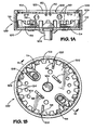
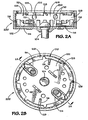
- Figures 2A-2C illustrate various views of a food reducing mechanism which includes a horizontal toothed ledge working surface having horizontal and vertical teeth.
- Figure 3 illustrates a food reducing mechanism which includes a vertical grating or rasping surface.
- Figures 4A-4B illustrate various views of a food reducing mechanism which includes the incorporation of serrated edges on the vertical edge of the teeth in an otherwise standard shredder ring.
- a rotatable plate 102 is coupled to a shaft 104 of a motor (not shown) housed in the disposer (not shown).
- a stationary ring 106 is disposed in the disposer and has an inner wall 108 disposed about the circumference of the rotatable plate 102.
- the inner wall 108 is preferably substantially vertical with respect to the horizontal plane of the rotatable plate 102.
- the stationary ring 106 is preferably composed of stainless steel, but alternatively may be composed of Ni-Hard.
- the inner wall 108 of the stationary ring 106 defines lower teeth 110 and breakers or diverters 112.
- the lower teeth 110 are positioned adjacent the rotatable plate 102 and the location where the weighted ends 116 of the movable lugs 114 pass when the disposer is operated.
- the lower teeth 110 are used as a grinding surface for food waste impacted and moved thereon as the lugs 114/118 and rotatable plate 102 are rotated during operation.
- the breakers or diverters 112 are preferably provided as inwardly projecting tabs, but also may also be provided as inwardly projecting splines. It is envisioned that other techniques and methods can be used for the construction of the stationary ring 106 and its features. For example, details of stationary rings that can be used with the disclosed reduction mechanisms are disclosed in U.S. Patent Nos. 6,007,006 and 6,439,487 , which are incorporated herein by reference in their entirety.
- One or more movable lugs 114 are attached to the peripheral portion of the rotatable plate 102 and have weighted ends 116 for passing adjacent the stationary ring 106 for shearing the food waste during operation.
- two movable lugs 114 are used.
- the movable lugs 114 can be movably attached to the rotatable plate 102 and capable of swiveling and sliding relative to the rotatable plate 102.
- Fixed lugs 118 can also be attached to rotatable plate 102. At least some of the fixed lugs 118 preferably have ends 120 that pass adjacent the inner wall 108. Interaction between the fixed lugs 118 and the stationary ring 106 produce shearing or cutting forces for reducing the food waste.
- a combination of fixed lugs 118 and movable lugs 114 can be used on the rotatable plate 102.
- the lugs 118/114 used in the disclosed embodiments herein are forged, cast, or machined and have substantially sharp edges.
- friable food waste can be reduced to smaller particles by the mere impacts with the rotatable plate 102, lugs 118/114, and inner wall 108.
- the food waste is also reduced to smaller particles by the grinding forces or frictional interaction between the weighted ends 116 of the movable lugs 114 or the ends 120 of the fixed lugs 118 and the inner wall 108 with teeth 110 of the stationary ring 106.
- FIG. 1A-1C an embodiment of a reduction mechanism 100 having a horizontal toothed ledge 122 working surface having horizontal teeth 124 is illustrated.
- Figure 1A shows the reduction mechanism 100 in side cross-section
- Figure 1B shows the reduction mechanism 100 in a top view
- Figure 1C shows the reduction mechanism 100 in a perspective view.
- the horizontal toothed ledge 122 is positioned directly above the stationary shredder ring 106 in a plastic adaptor 125 that can be directly inserted into the disposal grind chamber.
- the preferred embodiment of horizontal toothed ledge 122 as best shown in Figure 1B , comprises a flat ring formed with twenty-four equally spaced truncated teeth 124 separated by semicircular openings 126.
- FIG. 2A-2C an embodiment of a reduction mechanism 200 having a horizontal toothed ledge 128 working surface having horizontal and vertical teeth is illustrated.
- Figure 2A shows the reduction mechanism 200 in side cross-section
- Figure 2B shows the reduction mechanism 200 in a top view
- Figure 2C shows the reduction mechanism 200 in a perspective view.
- This embodiment is similar to the one illustrated in Figures 1A and 1B , except this configuration has eight teeth, four of which are horizontally oriented (130) and four of which have a vertically-oriented downward edge (132).
- the horizontal toothed ledge 128 is positioned directly above the stationary shredder ring 106 in a plastic adaptor 125 that can be directly inserted into the disposal grind chamber.
- FIG. 3 another embodiment of a reduction mechanism 300 having a vertical grating or rasping surface 150 is illustrated.
- the grating or rasping surface 150 is preferably located against the inner wall of the container body above the stationary shredder ring 106, as illustrated in Figures 3 .
- this grating or rasping surface 150 is constructed using a Microplane ® flexible woodworker's rasp or a similar equivalent, which is secured to the container body by screws 152. This type of surface in conjunction with the disclosed lugs configurations has been shown to be very effective at completely grinding and discharging large loads of leafy fibrous material.
- FIGS 4A-4B yet another embodiment of a reduction mechanism 400 having serrated edges 160 on the vertical edge of the teeth 110 in an otherwise standard stationary shredder ring 106 is illustrated.
- Figure 4A shows a perspective view of reduction mechanism 400
- Figure 4B shows a close-up cutaway view of serrated edges 160 on teeth 110.
- serrated edges 160 are added to the leading vertical edge of each tooth 110 in the stationary shredder ring 106.
- This ring design particularly when used in conjunction with the disclosed grinding lug configurations, has been shown to be effective in completely grinding and discharging large loads of fibrous food wastes such as corn husks.
- the serrated edge approach of Figures 4A and 4B can be used with any of the approaches disclosed in Figures 1A-1C , 2A-2C , or 3 .
- the grating or rasping surface approach of Figure 3 can be used with any of the approaches disclosed in Figures 1A-1C , 2A-2C , or 4A-4B .
- the rasping surface can be incorporated into the stationary shredder ring, i.e., teeth can be cut out of the rasping surface to in effect make a rasped shredder ling, or alternatively a rasped surface could appear on the upper edge of the shredder ring where the teeth are not present.
- the embodiments and approaches disclosed herein can also be used in conjunction with the approaches and embodiments disclosed in the above-incorporated U.S. Patent Application No. 10/790,311 .
- the term "plate” is not meant to necessarily refer to a unitary body, or a body that is flat.
- the term “ring” is not meant to strictly refer to a unitary body having a continuous annular shape, nor a body having constant inner and outer diameters; multiple components may be arranged in a ring shape, and accordingly may still together be considered to constitute a "ring.”
Landscapes
- Engineering & Computer Science (AREA)
- Environmental & Geological Engineering (AREA)
- Health & Medical Sciences (AREA)
- Life Sciences & Earth Sciences (AREA)
- Hydrology & Water Resources (AREA)
- Public Health (AREA)
- Water Supply & Treatment (AREA)
- Crushing And Pulverization Processes (AREA)
Claims (3)
- Broyeur à déchets alimentaires comportant un boîtier et une source de rotation, comprenant :une section de transport d'aliments du boîtier pour recevoir des déchets alimentaires ;une section motorisée du boîtier comportant la source de rotation ; etune section de broyage du boîtier recevant les déchets alimentaires à partir de la section de transport d'aliments et comportant une sortie d'évacuation, la section de broyage comprenant :une bague stationnaire (106) disposée dans le boîtier et comportant une paroi intérieure (108), dans lequel la paroi intérieure (108) de la bague stationnaire (106) définit une pluralité de dents (110), et dans lequel au moins une parmi la pluralité de dents (110) comporte un bord dentelé (160), une plaque rotative (102) accouplée avec la source de rotation et positionnée pour la rotation par rapport à la paroi intérieure (108) de la bague stationnaire (106), et au moins une oreille (114, 118) fixée à la plaque rotative (102).
- Broyeur à déchets alimentaires selon la revendication 1, dans lequel le bord dentelé (160) est situé sur un bord vertical d'attaque de chaque dent (110) ; et/ou dans lequel au moins une oreille (118) est une oreille fixe (118) ; et de préférence dans lequel l'oreille fixe (118) comporte une extrémité (120) pour passer de façon adjacente à la paroi intérieure (108) de la bague stationnaire (106).
- Broyeur à déchets alimentaires selon la revendication 1, dans lequel au moins une oreille (114) est une oreille mobile (114) et de préférence dans lequel l'oreille mobile (114) comporte une extrémité (116) pour passer de façon adjacente à la paroi intérieure (108) de la bague stationnaire (106).
Applications Claiming Priority (3)
| Application Number | Priority Date | Filing Date | Title |
|---|---|---|---|
| US47638603P | 2003-06-06 | 2003-06-06 | |
| US10/859,895 US7607599B2 (en) | 2003-06-06 | 2004-06-03 | Food waste reduction mechanism for disposer |
| EP04754420A EP1636436B1 (fr) | 2003-06-06 | 2004-06-04 | Mecanisme de reduction de dechets alimentaires pour broyeur |
Related Parent Applications (1)
| Application Number | Title | Priority Date | Filing Date |
|---|---|---|---|
| EP04754420.0 Division | 2004-06-04 |
Publications (3)
| Publication Number | Publication Date |
|---|---|
| EP2372030A2 EP2372030A2 (fr) | 2011-10-05 |
| EP2372030A3 EP2372030A3 (fr) | 2012-08-22 |
| EP2372030B1 true EP2372030B1 (fr) | 2013-10-30 |
Family
ID=33493534
Family Applications (2)
| Application Number | Title | Priority Date | Filing Date |
|---|---|---|---|
| EP11171625.4A Active EP2372030B1 (fr) | 2003-06-06 | 2004-06-04 | Mécanisme de réduction de déchets alimentaires pour broyeur |
| EP04754420A Active EP1636436B1 (fr) | 2003-06-06 | 2004-06-04 | Mecanisme de reduction de dechets alimentaires pour broyeur |
Family Applications After (1)
| Application Number | Title | Priority Date | Filing Date |
|---|---|---|---|
| EP04754420A Active EP1636436B1 (fr) | 2003-06-06 | 2004-06-04 | Mecanisme de reduction de dechets alimentaires pour broyeur |
Country Status (7)
| Country | Link |
|---|---|
| US (2) | US7607599B2 (fr) |
| EP (2) | EP2372030B1 (fr) |
| JP (1) | JP2007526107A (fr) |
| AT (1) | ATE549467T1 (fr) |
| AU (1) | AU2004245078A1 (fr) |
| ES (1) | ES2384103T3 (fr) |
| WO (1) | WO2004108292A1 (fr) |
Families Citing this family (31)
| Publication number | Priority date | Publication date | Assignee | Title |
|---|---|---|---|---|
| WO2005105311A1 (fr) * | 2004-04-26 | 2005-11-10 | Emerson Electric Co. | Ensemble broyeur distributeur de dechets alimentaires |
| US7651041B2 (en) | 2007-05-30 | 2010-01-26 | Chiaphua Components Limited | Food waste disposer |
| CN101628251B (zh) * | 2008-07-17 | 2012-12-05 | 德昌电机(深圳)有限公司 | 食品垃圾处理装置 |
| JP2012005945A (ja) * | 2010-06-24 | 2012-01-12 | Shinwa Kikai Sangyo:Kk | 破砕処理装置 |
| US8500050B2 (en) * | 2010-10-04 | 2013-08-06 | Emerson Electric Co. | Food waste disposer with restricted grind chamber discharge |
| DE102011115564A1 (de) * | 2011-06-07 | 2012-12-13 | Avermann Laser- und Kant-Zentrum GmbH | Zerkleinerungsvorrichtung für Speise- und Lebensmittelabfälle, insbesondere im gastronomischen Bereich, sowie Verfahren zum Betreiben einer derartigen Zerkleinerungsvorrichtung |
| JP3191841U (ja) | 2011-07-08 | 2014-07-17 | エマソン エレクトリック コー. | 食品偏向ハウジングを有する食品廃棄物ディスポーザ |
| SE536898C2 (sv) * | 2012-10-31 | 2014-10-21 | Diskomat Ab | Anordning för att finfördela matavfall innefattande ben. |
| US20140319252A1 (en) * | 2013-04-26 | 2014-10-30 | Emerson Electric Co. | Food Waste Disposer With Stamped Swivel Lugs |
| KR101450206B1 (ko) * | 2013-06-19 | 2014-10-14 | 서경태 | 오존을 활용한 싱크대용 음식물 쓰레기 분쇄 처리장치 |
| US9458613B2 (en) | 2013-10-28 | 2016-10-04 | Haier Us Appliance Solutions, Inc. | Waste disposal with improved housing configuration |
| US9869077B2 (en) | 2013-10-28 | 2018-01-16 | Haier Us Appliance Solutions, Inc. | Waste disposal with improved cutter plate features |
| US9506231B2 (en) | 2013-10-28 | 2016-11-29 | Haier Us Appliance Solutions, Inc. | Waste disposal system with improved mounting assembly |
| US9222246B2 (en) | 2013-10-28 | 2015-12-29 | General Electric Company | Waste disposal with enhanced water management features |
| US11344052B2 (en) | 2014-06-11 | 2022-05-31 | Goodnature Products, Inc. | Partial or whole food hopper, grinder and cold press counter-top juicing machine, system and method |
| CA2951898A1 (fr) | 2014-06-11 | 2015-12-17 | Eric Wettlaufer | Appareil et procedes de pressage de jus |
| CN104624299B (zh) * | 2015-02-11 | 2017-08-04 | 四川利达华锐机械有限公司 | 一种超微粉碎机 |
| CN105011767B (zh) * | 2015-08-07 | 2019-02-26 | 浙江绍兴苏泊尔生活电器有限公司 | 带刀片式精磨器及包括其的豆浆机 |
| CN105615700B (zh) * | 2016-03-15 | 2017-11-17 | 林越来 | 一种精磨组件及使用该精磨组件的设备 |
| CH712632A2 (fr) * | 2016-06-28 | 2017-12-29 | Frewitt Fabrique De Machines Sa | Dispositif de broyage. |
| US10645966B2 (en) | 2017-11-30 | 2020-05-12 | Goodnature Products, Inc. | Apparatus for grinding food |
| US11280075B2 (en) | 2019-01-29 | 2022-03-22 | Fb Global Plumbing Group Llc | Disposal with above sink installation |
| JP7283913B2 (ja) * | 2019-02-14 | 2023-05-30 | 安永エアポンプ株式会社 | ディスポーザ |
| US11844466B2 (en) | 2019-05-24 | 2023-12-19 | Goodnature Products, Inc. | Juicing devices with a removable grinder |
| USD914464S1 (en) | 2019-09-12 | 2021-03-30 | Goodnature Products, Inc. | Press box |
| USD918656S1 (en) | 2019-09-12 | 2021-05-11 | Goodnature Products, Inc. | Pusher |
| USD914465S1 (en) | 2019-09-12 | 2021-03-30 | Goodnature Products, Inc. | Juicing device |
| USD915156S1 (en) | 2020-09-15 | 2021-04-06 | Goodnature Products, Inc. | Press box |
| USD916565S1 (en) | 2020-09-15 | 2021-04-20 | Goodnature Products, Inc. | Juicing device |
| US20220274119A1 (en) * | 2021-02-26 | 2022-09-01 | Emerson Electric Co. | Food waste disposer with grating ring |
| US20230001421A1 (en) * | 2021-07-02 | 2023-01-05 | Emerson Electric Co. | Grinding mechanism for food waste disposer |
Family Cites Families (44)
| Publication number | Priority date | Publication date | Assignee | Title |
|---|---|---|---|---|
| US436496A (en) * | 1890-09-16 | Rudolph e | ||
| US1174656A (en) | 1915-06-28 | 1916-03-07 | Arthur J Beckwith | Garbage-consumer. |
| US1459713A (en) | 1922-04-18 | 1923-06-26 | Leslie W Beggs | Garbage destroyer |
| US2004737A (en) | 1930-11-17 | 1935-06-11 | Tonks Mfg Company | Wood hog |
| US1965033A (en) | 1931-06-08 | 1934-07-03 | Garbage Eliminator Inc | Garbage reducing machine |
| US2044563A (en) | 1931-10-15 | 1936-06-16 | Gen Electric | Grinding machine |
| US2012680A (en) | 1933-05-22 | 1935-08-27 | John W Hammes | Garbage disposal device |
| US2044564A (en) | 1933-08-29 | 1936-06-16 | Gen Electric | Grinding machine |
| US2225171A (en) | 1937-11-03 | 1940-12-17 | John W Hammes | Garbage disposal apparatus |
| GB630494A (en) | 1945-10-18 | 1949-10-14 | Eureka Williams Corp | Improvements in or relating to garbage grinders |
| US2579400A (en) * | 1946-05-07 | 1951-12-18 | Lockley Machine Company | Garbage grinding device |
| GB719509A (en) | 1952-09-09 | 1954-12-01 | New Zealand Textile Engineers | Improvements in or relating to apparatus for disintegrating solids in garbage or thelike waste |
| US2833484A (en) * | 1954-04-16 | 1958-05-06 | Diamond Alkali Co | Hammer mill and screen |
| GB771419A (en) | 1954-07-14 | 1957-04-03 | Westinghouse Electric Int Co | Improvements in or relating to food waste disposer apparatus |
| US2940677A (en) * | 1954-09-27 | 1960-06-14 | Given Machinery Company | Disposal device for culinary waste |
| US2829838A (en) * | 1955-12-14 | 1958-04-08 | Gen Electric | Waste disposal apparatus |
| US3025117A (en) | 1958-03-25 | 1962-03-13 | Callaway Mills Co | Lubricating pads for journal boxes |
| US2933964A (en) * | 1958-04-07 | 1960-04-26 | Wittlin Albert | Device for unjamming a garbage disposal device |
| GB880821A (en) | 1959-08-04 | 1961-10-25 | British Doby Stokers Ltd | An improved apparatus for disintegrating garbage |
| US3026050A (en) | 1959-08-28 | 1962-03-20 | Gen Electric | Food waste disposer |
| US3113735A (en) * | 1961-08-22 | 1963-12-10 | Gen Electric | Rotatable assembly for food waste disposers and the like |
| US3211389A (en) | 1961-10-16 | 1965-10-12 | Salvajor Company | Rotor assembly for food waste disposers |
| US3236462A (en) * | 1962-10-26 | 1966-02-22 | Fmc Corp | Waste disposer |
| US3335970A (en) * | 1965-01-05 | 1967-08-15 | Gen Electric | Food waste disposer |
| US3589624A (en) | 1968-10-24 | 1971-06-29 | Maytag Co | Waste disposer with liner |
| GB1308229A (en) | 1970-08-12 | 1973-02-21 | Johnson A G | Food waste disposal units |
| US3804341A (en) | 1972-06-09 | 1974-04-16 | Gen Electric | Waste food disposer |
| US3875462A (en) | 1973-02-01 | 1975-04-01 | Gen Electric | Food waste disposer |
| US3862720A (en) | 1973-09-06 | 1975-01-28 | Gen Electric | Waste disposer installation |
| US4134555A (en) | 1977-01-25 | 1979-01-16 | Rosselet Charles R | Waste disposer |
| US4128210A (en) | 1977-03-24 | 1978-12-05 | Whirlpool Corporation | Food waste disposal apparatus |
| US4183470A (en) | 1978-04-03 | 1980-01-15 | Lorraine Linder | Water actuated disposer |
| US4573642A (en) | 1984-05-07 | 1986-03-04 | Wastemate Corporation | Water powered waste disposer with improved dynamic seal |
| US4776523A (en) | 1987-09-01 | 1988-10-11 | Hurst Hubert L | Waste food disposer |
| US4917311A (en) | 1988-09-27 | 1990-04-17 | Mitsubishi Denki Kabushiki Kaisha | Garbage disposer |
| JP2597021B2 (ja) | 1990-02-22 | 1997-04-02 | 楢夫 新矢 | 生ゴミ粉砕処理装置 |
| JPH06114283A (ja) * | 1992-10-09 | 1994-04-26 | Kubota Corp | 厨芥処理装置 |
| US5340036A (en) | 1993-05-19 | 1994-08-23 | Emerson Electric Co. | Dry waste grinder |
| US6007006A (en) | 1998-07-23 | 1999-12-28 | Emerson Electric Co. | Food waste disposer |
| JP3640203B2 (ja) * | 1998-08-31 | 2005-04-20 | 清水建設株式会社 | 生ゴミ処理機および生ゴミ資源化システム |
| JP3029620B1 (ja) * | 1999-03-08 | 2000-04-04 | 株式会社 森製作所 | 廃タイヤの粉砕方法及びその装置 |
| US6439487B1 (en) | 2000-03-14 | 2002-08-27 | Emerson Electric Co. | Grinding mechanism for a food waste disposer and method of making the grinding mechanism |
| USD436496S1 (en) | 2000-03-14 | 2001-01-23 | Emerson Electric Co. | Fixed lug plate in a food waste disposer |
| US6481652B2 (en) | 2000-11-28 | 2002-11-19 | Emerson Electric Co. | Food waste disposer having variable speed motor and methods of operating same |
-
2004
- 2004-06-03 US US10/859,895 patent/US7607599B2/en active Active
- 2004-06-04 WO PCT/US2004/017809 patent/WO2004108292A1/fr active Application Filing
- 2004-06-04 JP JP2006515211A patent/JP2007526107A/ja active Pending
- 2004-06-04 EP EP11171625.4A patent/EP2372030B1/fr active Active
- 2004-06-04 ES ES04754420T patent/ES2384103T3/es active Active
- 2004-06-04 AU AU2004245078A patent/AU2004245078A1/en not_active Abandoned
- 2004-06-04 EP EP04754420A patent/EP1636436B1/fr active Active
- 2004-06-04 AT AT04754420T patent/ATE549467T1/de active
-
2009
- 2009-09-16 US US12/560,636 patent/US7866583B2/en not_active Expired - Fee Related
Also Published As
| Publication number | Publication date |
|---|---|
| EP1636436B1 (fr) | 2012-03-14 |
| EP1636436A1 (fr) | 2006-03-22 |
| ATE549467T1 (de) | 2012-03-15 |
| ES2384103T3 (es) | 2012-06-29 |
| WO2004108292A1 (fr) | 2004-12-16 |
| EP2372030A3 (fr) | 2012-08-22 |
| AU2004245078A1 (en) | 2004-12-16 |
| JP2007526107A (ja) | 2007-09-13 |
| US7607599B2 (en) | 2009-10-27 |
| US7866583B2 (en) | 2011-01-11 |
| US20100006682A1 (en) | 2010-01-14 |
| EP2372030A2 (fr) | 2011-10-05 |
| US20040245358A1 (en) | 2004-12-09 |
Similar Documents
| Publication | Publication Date | Title |
|---|---|---|
| EP2372030B1 (fr) | Mécanisme de réduction de déchets alimentaires pour broyeur | |
| JP5019690B2 (ja) | 食品ゴミディスポーザ用粉砕機構 | |
| EP1723286B1 (fr) | Broyeur a dechets alimentaires | |
| AU2008346759B2 (en) | Food waste disposer with grinding mechanism with windowed grind ring | |
| US20070075169A1 (en) | Waste food disposal unit | |
| US20070114310A1 (en) | Food waste reduction mechanism for disposer | |
| EP1988223B1 (fr) | Unité d'évacuation de déchets alimentaires | |
| CA2528212A1 (fr) | Mecanisme de reduction de dechets alimentaires pour broyeur |
Legal Events
| Date | Code | Title | Description |
|---|---|---|---|
| PUAI | Public reference made under article 153(3) epc to a published international application that has entered the european phase |
Free format text: ORIGINAL CODE: 0009012 |
|
| AC | Divisional application: reference to earlier application |
Ref document number: 1636436 Country of ref document: EP Kind code of ref document: P |
|
| AK | Designated contracting states |
Kind code of ref document: A2 Designated state(s): AT BE BG CH CY CZ DE DK EE ES FI FR GB GR HU IE IT LI LU MC NL PL PT RO SE SI SK TR |
|
| PUAL | Search report despatched |
Free format text: ORIGINAL CODE: 0009013 |
|
| AK | Designated contracting states |
Kind code of ref document: A3 Designated state(s): AT BE BG CH CY CZ DE DK EE ES FI FR GB GR HU IE IT LI LU MC NL PL PT RO SE SI SK TR |
|
| RIC1 | Information provided on ipc code assigned before grant |
Ipc: E03C 1/266 20060101AFI20120713BHEP |
|
| 17P | Request for examination filed |
Effective date: 20121015 |
|
| GRAP | Despatch of communication of intention to grant a patent |
Free format text: ORIGINAL CODE: EPIDOSNIGR1 |
|
| INTG | Intention to grant announced |
Effective date: 20130613 |
|
| GRAS | Grant fee paid |
Free format text: ORIGINAL CODE: EPIDOSNIGR3 |
|
| GRAA | (expected) grant |
Free format text: ORIGINAL CODE: 0009210 |
|
| AC | Divisional application: reference to earlier application |
Ref document number: 1636436 Country of ref document: EP Kind code of ref document: P |
|
| AK | Designated contracting states |
Kind code of ref document: B1 Designated state(s): AT BE BG CH CY CZ DE DK EE ES FI FR GB GR HU IE IT LI LU MC NL PL PT RO SE SI SK TR |
|
| REG | Reference to a national code |
Ref country code: GB Ref legal event code: FG4D |
|
| REG | Reference to a national code |
Ref country code: CH Ref legal event code: EP |
|
| REG | Reference to a national code |
Ref country code: AT Ref legal event code: REF Ref document number: 638532 Country of ref document: AT Kind code of ref document: T Effective date: 20131115 |
|
| REG | Reference to a national code |
Ref country code: IE Ref legal event code: FG4D |
|
| REG | Reference to a national code |
Ref country code: DE Ref legal event code: R096 Ref document number: 602004043710 Country of ref document: DE Effective date: 20131224 |
|
| REG | Reference to a national code |
Ref country code: ES Ref legal event code: FG2A Ref document number: 2444544 Country of ref document: ES Kind code of ref document: T3 Effective date: 20140225 |
|
| REG | Reference to a national code |
Ref country code: NL Ref legal event code: VDEP Effective date: 20131030 |
|
| REG | Reference to a national code |
Ref country code: AT Ref legal event code: MK05 Ref document number: 638532 Country of ref document: AT Kind code of ref document: T Effective date: 20131030 |
|
| PG25 | Lapsed in a contracting state [announced via postgrant information from national office to epo] |
Ref country code: SE Free format text: LAPSE BECAUSE OF FAILURE TO SUBMIT A TRANSLATION OF THE DESCRIPTION OR TO PAY THE FEE WITHIN THE PRESCRIBED TIME-LIMIT Effective date: 20131030 Ref country code: FI Free format text: LAPSE BECAUSE OF FAILURE TO SUBMIT A TRANSLATION OF THE DESCRIPTION OR TO PAY THE FEE WITHIN THE PRESCRIBED TIME-LIMIT Effective date: 20131030 Ref country code: NL Free format text: LAPSE BECAUSE OF FAILURE TO SUBMIT A TRANSLATION OF THE DESCRIPTION OR TO PAY THE FEE WITHIN THE PRESCRIBED TIME-LIMIT Effective date: 20131030 Ref country code: BE Free format text: LAPSE BECAUSE OF FAILURE TO SUBMIT A TRANSLATION OF THE DESCRIPTION OR TO PAY THE FEE WITHIN THE PRESCRIBED TIME-LIMIT Effective date: 20131030 |
|
| PG25 | Lapsed in a contracting state [announced via postgrant information from national office to epo] |
Ref country code: AT Free format text: LAPSE BECAUSE OF FAILURE TO SUBMIT A TRANSLATION OF THE DESCRIPTION OR TO PAY THE FEE WITHIN THE PRESCRIBED TIME-LIMIT Effective date: 20131030 Ref country code: CY Free format text: LAPSE BECAUSE OF FAILURE TO SUBMIT A TRANSLATION OF THE DESCRIPTION OR TO PAY THE FEE WITHIN THE PRESCRIBED TIME-LIMIT Effective date: 20131030 |
|
| PG25 | Lapsed in a contracting state [announced via postgrant information from national office to epo] |
Ref country code: PT Free format text: LAPSE BECAUSE OF FAILURE TO SUBMIT A TRANSLATION OF THE DESCRIPTION OR TO PAY THE FEE WITHIN THE PRESCRIBED TIME-LIMIT Effective date: 20140228 |
|
| PG25 | Lapsed in a contracting state [announced via postgrant information from national office to epo] |
Ref country code: EE Free format text: LAPSE BECAUSE OF FAILURE TO SUBMIT A TRANSLATION OF THE DESCRIPTION OR TO PAY THE FEE WITHIN THE PRESCRIBED TIME-LIMIT Effective date: 20131030 |
|
| REG | Reference to a national code |
Ref country code: DE Ref legal event code: R097 Ref document number: 602004043710 Country of ref document: DE |
|
| PG25 | Lapsed in a contracting state [announced via postgrant information from national office to epo] |
Ref country code: SK Free format text: LAPSE BECAUSE OF FAILURE TO SUBMIT A TRANSLATION OF THE DESCRIPTION OR TO PAY THE FEE WITHIN THE PRESCRIBED TIME-LIMIT Effective date: 20131030 Ref country code: CZ Free format text: LAPSE BECAUSE OF FAILURE TO SUBMIT A TRANSLATION OF THE DESCRIPTION OR TO PAY THE FEE WITHIN THE PRESCRIBED TIME-LIMIT Effective date: 20131030 Ref country code: RO Free format text: LAPSE BECAUSE OF FAILURE TO SUBMIT A TRANSLATION OF THE DESCRIPTION OR TO PAY THE FEE WITHIN THE PRESCRIBED TIME-LIMIT Effective date: 20131030 Ref country code: PL Free format text: LAPSE BECAUSE OF FAILURE TO SUBMIT A TRANSLATION OF THE DESCRIPTION OR TO PAY THE FEE WITHIN THE PRESCRIBED TIME-LIMIT Effective date: 20131030 |
|
| PLBE | No opposition filed within time limit |
Free format text: ORIGINAL CODE: 0009261 |
|
| STAA | Information on the status of an ep patent application or granted ep patent |
Free format text: STATUS: NO OPPOSITION FILED WITHIN TIME LIMIT |
|
| PG25 | Lapsed in a contracting state [announced via postgrant information from national office to epo] |
Ref country code: DK Free format text: LAPSE BECAUSE OF FAILURE TO SUBMIT A TRANSLATION OF THE DESCRIPTION OR TO PAY THE FEE WITHIN THE PRESCRIBED TIME-LIMIT Effective date: 20131030 |
|
| 26N | No opposition filed |
Effective date: 20140731 |
|
| REG | Reference to a national code |
Ref country code: DE Ref legal event code: R097 Ref document number: 602004043710 Country of ref document: DE Effective date: 20140731 |
|
| REG | Reference to a national code |
Ref country code: DE Ref legal event code: R119 Ref document number: 602004043710 Country of ref document: DE |
|
| PG25 | Lapsed in a contracting state [announced via postgrant information from national office to epo] |
Ref country code: LU Free format text: LAPSE BECAUSE OF FAILURE TO SUBMIT A TRANSLATION OF THE DESCRIPTION OR TO PAY THE FEE WITHIN THE PRESCRIBED TIME-LIMIT Effective date: 20140604 Ref country code: MC Free format text: LAPSE BECAUSE OF FAILURE TO SUBMIT A TRANSLATION OF THE DESCRIPTION OR TO PAY THE FEE WITHIN THE PRESCRIBED TIME-LIMIT Effective date: 20131030 |
|
| REG | Reference to a national code |
Ref country code: CH Ref legal event code: PL |
|
| PG25 | Lapsed in a contracting state [announced via postgrant information from national office to epo] |
Ref country code: SI Free format text: LAPSE BECAUSE OF FAILURE TO SUBMIT A TRANSLATION OF THE DESCRIPTION OR TO PAY THE FEE WITHIN THE PRESCRIBED TIME-LIMIT Effective date: 20131030 |
|
| REG | Reference to a national code |
Ref country code: IE Ref legal event code: MM4A |
|
| REG | Reference to a national code |
Ref country code: FR Ref legal event code: ST Effective date: 20150227 |
|
| REG | Reference to a national code |
Ref country code: DE Ref legal event code: R119 Ref document number: 602004043710 Country of ref document: DE Effective date: 20150101 |
|
| PG25 | Lapsed in a contracting state [announced via postgrant information from national office to epo] |
Ref country code: LI Free format text: LAPSE BECAUSE OF NON-PAYMENT OF DUE FEES Effective date: 20140630 Ref country code: IE Free format text: LAPSE BECAUSE OF NON-PAYMENT OF DUE FEES Effective date: 20140604 Ref country code: CH Free format text: LAPSE BECAUSE OF NON-PAYMENT OF DUE FEES Effective date: 20140630 Ref country code: DE Free format text: LAPSE BECAUSE OF NON-PAYMENT OF DUE FEES Effective date: 20150101 |
|
| PG25 | Lapsed in a contracting state [announced via postgrant information from national office to epo] |
Ref country code: FR Free format text: LAPSE BECAUSE OF NON-PAYMENT OF DUE FEES Effective date: 20140630 |
|
| PG25 | Lapsed in a contracting state [announced via postgrant information from national office to epo] |
Ref country code: BG Free format text: LAPSE BECAUSE OF FAILURE TO SUBMIT A TRANSLATION OF THE DESCRIPTION OR TO PAY THE FEE WITHIN THE PRESCRIBED TIME-LIMIT Effective date: 20131030 |
|
| PG25 | Lapsed in a contracting state [announced via postgrant information from national office to epo] |
Ref country code: GR Free format text: LAPSE BECAUSE OF FAILURE TO SUBMIT A TRANSLATION OF THE DESCRIPTION OR TO PAY THE FEE WITHIN THE PRESCRIBED TIME-LIMIT Effective date: 20140131 |
|
| PG25 | Lapsed in a contracting state [announced via postgrant information from national office to epo] |
Ref country code: HU Free format text: LAPSE BECAUSE OF FAILURE TO SUBMIT A TRANSLATION OF THE DESCRIPTION OR TO PAY THE FEE WITHIN THE PRESCRIBED TIME-LIMIT; INVALID AB INITIO Effective date: 20040604 Ref country code: TR Free format text: LAPSE BECAUSE OF FAILURE TO SUBMIT A TRANSLATION OF THE DESCRIPTION OR TO PAY THE FEE WITHIN THE PRESCRIBED TIME-LIMIT Effective date: 20131030 |
|
| PGFP | Annual fee paid to national office [announced via postgrant information from national office to epo] |
Ref country code: IT Payment date: 20200519 Year of fee payment: 17 |
|
| PGFP | Annual fee paid to national office [announced via postgrant information from national office to epo] |
Ref country code: ES Payment date: 20200701 Year of fee payment: 17 |
|
| PG25 | Lapsed in a contracting state [announced via postgrant information from national office to epo] |
Ref country code: IT Free format text: LAPSE BECAUSE OF NON-PAYMENT OF DUE FEES Effective date: 20210604 |
|
| REG | Reference to a national code |
Ref country code: ES Ref legal event code: FD2A Effective date: 20220801 |
|
| PG25 | Lapsed in a contracting state [announced via postgrant information from national office to epo] |
Ref country code: ES Free format text: LAPSE BECAUSE OF NON-PAYMENT OF DUE FEES Effective date: 20210605 |
|
| P01 | Opt-out of the competence of the unified patent court (upc) registered |
Effective date: 20230523 |
|
| PGFP | Annual fee paid to national office [announced via postgrant information from national office to epo] |
Ref country code: GB Payment date: 20230413 Year of fee payment: 20 |