EP2369045B1 - Knitted fabric, knitting method thereof and designing apparatus - Google Patents
Knitted fabric, knitting method thereof and designing apparatus Download PDFInfo
- Publication number
- EP2369045B1 EP2369045B1 EP11002149.0A EP11002149A EP2369045B1 EP 2369045 B1 EP2369045 B1 EP 2369045B1 EP 11002149 A EP11002149 A EP 11002149A EP 2369045 B1 EP2369045 B1 EP 2369045B1
- Authority
- EP
- European Patent Office
- Prior art keywords
- knitting
- needle
- yarn
- stitch
- knitted fabric
- Prior art date
- Legal status (The legal status is an assumption and is not a legal conclusion. Google has not performed a legal analysis and makes no representation as to the accuracy of the status listed.)
- Active
Links
- 238000009940 knitting Methods 0.000 title claims description 182
- 239000004744 fabric Substances 0.000 title claims description 69
- 238000000034 method Methods 0.000 title claims description 45
- 239000000969 carrier Substances 0.000 description 8
- 238000010586 diagram Methods 0.000 description 4
- 238000004891 communication Methods 0.000 description 3
- 230000002950 deficient Effects 0.000 description 2
- 230000003247 decreasing effect Effects 0.000 description 1
- 230000000694 effects Effects 0.000 description 1
- 230000002452 interceptive effect Effects 0.000 description 1
Images


Classifications
-
- D—TEXTILES; PAPER
- D04—BRAIDING; LACE-MAKING; KNITTING; TRIMMINGS; NON-WOVEN FABRICS
- D04B—KNITTING
- D04B1/00—Weft knitting processes for the production of fabrics or articles not dependent on the use of particular machines; Fabrics or articles defined by such processes
- D04B1/10—Patterned fabrics or articles
- D04B1/12—Patterned fabrics or articles characterised by thread material
Definitions
- the present invention relates to a knitted fabric, being knitted by a flatbed knitting machine and having areas knitted with different knitting yarns which are treated as cross - over yarns when used in other areas, to a knitting method thereof, and to use of a designing apparatus.
- the flatbed knitting machine is provided with at least a pair of needle beds, arranged opposite to each other to define a needle bed gap between them, and a cam system, mounted on a carriage movable in reciprocation along the needle beds, for driving knitting needles arranged in parallel over the needle beds.
- a yarn feeder rail is built over the needle bed gap, and yarn carriers movable along the yarn feeder rail are taken by the carriage to feed the knitting yarns to the knitting needles driven by the cam system, thereby the knitted fabric is knitted.
- a yarn feeder port, to which the knitting yarn is fed from the yarn carrier, is positioned at a higher level with respect to an overhead direction of the needle bed gap, in order to avoid interference with the knitting needles, than a moving range within which the hooks at the front ends of the knitting needles driven to form the stitches are moved.
- the knitting yarn is fed from such a higher level, since an edge portion of the knitting yarn fed is already held by the knitting needle or joined in the already knitted stitches of the knitted fabric or gripped by an edge yarn gripping device disposed at a lateral side of the needle bed, the knitting yarn is at a low level. With decreasing interval that allows the knitting yarn to be in the form of the cross - over yarn floating from the needle bed gap, the knitting yarn is lowered in height so that when the stitches are formed, the knitting yarn can be easily captured by a hook of a knitting needle.
- the knitting yarn With increasing distance that allows the knitting yarn to be in the form of the cross-over yarn which is not knitted in the knitted fabric as a stitch, the knitting yarn floats in height so that when a stitch is to be formed, the knitting yarn cannot be captured by a hook of a knitting needle.
- a knitting needle on the stitch passing side is advanced farther to the needle bed gap than in a stitch forming process.
- a latch needle used as a knitting needle can produce a result that when the latch is closed, a knitting yarn is drawn into a hook, so that, using a split knit technique, in which a stitch transfer is applied to form a stitch, provides an advantage that the cross-over yarn at the higher level can also be captured in a form of a new loop (See Patent Literature 1, for example).
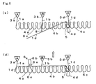
- Fig. 5 shows as an example applied with a knitting technique disclosed in the Patent Literature 1, that when a knitting yarn 1d is yarned in for an intarsia knitting, the knitting yarn 1d serving as the cross-over yarn which is positioned at a higher level from the needle bed gap is captured through the use of the split knit and thereafter the stitch is cast off by the captured knitting yarn 1d.
- the knitted fabric is knitted on the front needle bed.
- Fig. 5(a) shows the knitted fabric 2 to be knitted.
- the knitted fabric 2 is formed by combination of A area 2a, B area 2b, C area 2c, and D area 2d.
- the D area 2d is knitted before and after the C area 2c of small in number of courses.
- the yarn carrier 3d for feeding the knitting yarn 1d used for the knitting is moved outside of the knitting width.
- Fig. 5(b) shows the state in which the A areas 2a and B area 2b are respectively knitted with the knitting yarns 1a, 1b fed from the yarn carriers 3a, 3b.
- the stitches 4a, 4b are formed with the knitting needles of the front needle bed, and the stitch 4c is formed in the C area 2c.
- a tuck 5 is hooked on the stitch 4c at the left side of the C area 2c, through which the B area 2b and the C area 2c are joined.
- the A area 2a and the B area 2b are also joined in the same manner.
- FIG. 5(c) shows the state in which the knitting of the C area 2c is ended and the second half of the D area 2d starts knitting with the knitting yarn 1d fed from the yarn carrier 3d.
- Fig. 5(d) in the process of the yarn-in of the knitting yarn 1d, for example one of the stitches 4a in the A area 2a is transferred to the back needle bed before the split knit 6.
- the stitch 6a transferred to the knitting needle of the back needle bed turns into the old loop and a new loop of the stitch 6b is newly formed with the knitting yarn 1d, in order to prevent the floating of the cross-over yarn.
- the knitting yarn 1d can be reliably captured by the knitting needle at the left side of the D area 2d to form the stitch 4d.
- the stitch 6c is transferred to the knitting needle of the front needle bed.
- the stitch 6b formed with the knitting needle of the back needle bed is cast off from it, for convenience of later processes.
- the stitch 6b thus cast off turns into a cross-over yarn, so that the relation with the knitted fabric is cut.
- Fig. 6 shows another example of the phenomenon occurring in the process of yarn in during intarsia knitting, that the knitting yarn 1d positioned at a higher level from the needle bed gap is captured in the form of a new loop of the stitch 6b by the knitting needle of the back needle bed through the use of the split knit 6 and thereafter the stitch 6b is cast off. Since the processes (a) to (d) of Fig. 6 are the same as the processes (a) to (d) of Fig. 5 , the processes (a) to (c) are omitted.
- a plurality of yarn carriers 3a, 3b, 3d are used, they must be moved along tracks different in position from each other with respect to the back and forth direction, in order to be moved in the lateral direction, as viewed from the drawing, without interfering with each other.
- the yarn carriers are arranged in the order of 3a, 3d, 3b with respect to the back and forth direction from the front side, an intersection between the knitting yarns 11b, 11d is caused at the left side of the B area 2b.
- the knitting yarn 1d is pulled downwards and in turn the intersected knitting yarn 1b is pulled downwards, as shown in Fig. 6(e) , so that the knitting yarn 1b extending to the yarn carrier 3b from the stitch at the widthwise end of the B area 2b may be excessively increased in length to cause slackness 8.
- Patent Literature 1 WO 2007/119272 A1
- the knitting yarn 1d serving as the cross - over yarn is captured at a midpoint thereof by the hook of the latch needle through the use of the split knit, as is the case with the Patent Literature 1, the knitting yarn 1d can be lowered in level so that the first stitch can be reliably formed in the area 2d knitted with the knitting yarn 1d.
- the stitch, after formed, is cast off from the hook, there is a possibility that slackness 7, 8 as shown in Figs. 5 and 6 may be produced. If the slackness 7 as is shown in Fig. 5 is produced, there is a possibility that such slackness 7 also be caught for the knitting of the A area 2a and may be knitted in the knitted fabric to produce defective knit products.
- the present invention provides a knitted fabric being knitted by a flatbed knitting machine capable of split knit using latch needles, while a knitting yarn which is not used for forming stitches but serves as a cross-over yarn in at least a specific area of the knitted fabric being remained in the area through the use of a part of stitches in the area, wherein the knitting yarn serving as the cross-over yarn is overlapped with and remained in the stitches used in the state of being captured when split knit is carried out using the stitches.
- the present invention provides a knitting method of a knitted fabric comprising a process that when the knitted fabric is knitted by a flatbed knitting machine provided with at least a pair of front and back needle beds arranged opposite to each other to define a needle bed gap and a number of latch needles as knitting needles arranged on the respective needle beds, while a knitting yarn, which is different from that used for forming stitches but serves as a cross-over yarn, is remained in the knitted fabric through the use of a part of stitches in the knitted fabric, wherein the knitting yarn serving as the cross-over yarn, when split knit is provided between a holding needle for holding a part of the stitches used and an opposite needle opposite to the holding needle across the needle bed gap, is captured in the form of a newly formed loop by a hook of the knitting needle on the stitch transferring side in the split knit and thereafter the stitch held by the opposite needle is transferred and overlapped with the stitch held by the holding needle so that it can be remained in the form of one of the overlapped stitches in the knitted fabric.
- the stitch held by said holding needle is transferred to the opposite needle before said split knit is provided, then the split knit is carried out, with the opposite needle as the knitting needle on said stitch transferring side, so that the knitting yarn serving as the cross-over yarn is captured by the hook of the knitting needle in such a manner as to form the new loop, and then the new loop is transferred to and overlapped with the stitch held by the holding needle.
- the split knit is carried out, with said holding needle as the knitting needle on said stitch transferring side, so that the knitting yarn serving as the cross-over yarn is captured in the form of a new loop by the hook of the holding needle, and then the stitch held by the opposite needle is transferred to and overlapped with the stitch held by the holding needle.
- the knitting yarn serving as said cross-over yarn when the knitting yarn is yarned in from its standby state in which the kitting yarn is drawn outside the knitting width of the already knitted fabric and is dropped downwardly in the needle bed gap, intersects with a knitting yarn used for knitting the other area.
- the present invention provides a designing apparatus for use in a knitting method of a knitted fabric including a process that when the knitted fabric is knitted by a flatbed knitting machine provided with at least a pair of front and back needle beds arranged opposite to each other to define a needle bed gap and a number of latch needles as knitting needles arranged on the respective needle beds, while a knitting yarn, which is different from that used for forming stitches but serves as a cross-over yarn, is remained in the knitted fabric through the use of a part of stitches in the knitted fabric, comprising a means for generating knitting data in such a manner that the knitting yarn serving as the cross-over yarn, when split knit is provided between a holding needle for holding a part of the stitches used and an opposite needle opposite to the holding needle across the needle bed gap, is captured in the form of a new loop by a hook of the knitting needle on the stitch transferring side in the split knit and thereafter the stitch held by the opposite needle is transferred and overlapped with the stitch held by the holding needle so that it can be
- the knitted fabric is knitted by the flatbed knitting machine capable of split knit using latch needles.
- the knitting yarn serving as the cross-over yarn is captured and is remained in the state of the stitches being overlapped with each other in the area where the knitting yarn turns into the cross - over yarn floating from the knitted fabric.
- the knitting yarn corresponding to the cross - over yarn can be drawn out from the knitted fabric. This can bring the split stitch back to substantially the same state as the former state before the split knit.
- the cross - over yarn is remained in the knitted fabric. This can provide the result that the cross - over yarn can be prevented from being slackened to provide problem that may be caused by the slackness.
- the knitting yarn serving as the cross - over yarn can be reliably captured when the split knit is carried out for the stitch held by the holding needle.
- the cross - over yarn is transferred in such a manner that the stitch held by the opposite needle is overlapped with the stitch held by the holding needle so that it can be remained in the form of one of the overlapped stitches in the knitted fabric. This can prevent from occurrence of the problem that the knitting yarn may be slackened in the course of the knitting.
- the cross - over yarn can be drawn out and removed from the knitted fabric. Hence, the influence of the split knit can also be removed from the knitted fabric.
- the knitting process can be shortened
- the cross-over yarn is fed in from below within the knitting width of the knitted fabric to intersect with the other knitting yarn, since the cross-over yarn after captured is remained in the knitted fabric, the other intersecting knitting yarn can be prevented from being drawn downwardly.
- the knitting data can be generated that can allow the reliable capture via the split knit and prevent from occurrence of the problem resulting from the slackness after the capture
- FIG. 1 a knitting method of a certain embodiment of the present invention is explained.
- FIG. 3 another knitting method of another embodiment of the present invention is explained.
- latch needles are provided as knitting needles on a front needle bed and a back needle bed which are arranged opposite to each other to define a needle bed gap between them, explanation however is given on the case that a knitted fabric is knitted using the latch needles on the front needle bed.
- FIG. 4 a designing apparatus 30 which is still another embodiment of the present invention is explained.
- corresponding parts when presented in the preceding explanation, are sometimes labeled the same reference characters used in the preceding explanation throughout the drawings.
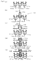
- Fig. 1 is a view showing schematically a stitch structure of a principal part of a knitting method of a certain embodiment of the present invention.
- Fig. 1(a) shows a state in which for example one course of stitches 11a, 11b, 11c are formed with latch needles 10a, 10b, 10c on the front needle bed of Fig. 5 .
- Fig. 1(b) shows a state in which the stitch 11b held by the latch needle 10b, which serves as a holding needle out of the latch needles 10a, 10b, 10c of Fig. 1(a) , is transferred to and held by a latch needle 13 on the back needle bed which corresponds in position to the latch needle 10b across a needle bed gap 12.
- Fig. 1 shows a state in which for example one course of stitches 11a, 11b, 11c are formed with latch needles 10a, 10b, 10c on the front needle bed of Fig. 5 .
- Fig. 1(b) shows a state in which the stitch 11b held
- FIG. 1(c) shows a state in which when a knitting yarn serving as a cross-over yarn 15 is yarned in, a split knit 16 is provided between the latch needle 10b on the front needle bed and the latch needle 13 on the back needle bed.
- the split knit 16 is provided for the transferred stitch 14a in Fig. 1(b) , the cross-over yarn 15 is captured by the hook of the latch needle 13 which is the opposite needle, on the back needle bed, and a stitch 15a is formed as a new loop, while also the transferred stitch 14a is knocked over as an old loop.
- a stitch 14b is formed with the latch needle 10b, which is the holding needle, on the front needle bed.
- the use of the split knit 16 can facilitate the capture of the cross-over yarn 15.
- Fig. 1(d) shows a state in which the stitch 15a formed with the latch needle 13 on the back needle bed in Fig. 1(c) is transferred to the latch needle 10b on the front needle bed and is overlapped with the stitch 14b held by the latch needle 10b to form double stitches 20.
- Fig. 1(e) shows a state in which stitches 21a, 21b, 21c in the course next to the course including the double stitches 20 are formed.
- stitches are formed by their respective latch needles 10a, 10b, 10c on the front needle bed in the same manner, to thereby produce a knitted fabric 22, and the knitted fabric 22 thus knitted can allow the cross-over yarn 15, shown in dashed line, to be removed by drawing out in the lateral direction 15x as viewed in the drawing.
- the stitch 14a which becomes an old loop in Fig. (c)
- the knitted fabric 22 is knitted on the front needle bed, since the cross - over yarn 15 remains in the back side of the knitted fabric 22 on the back needle bed side, the drawing of the cross - over yarn can be facilitated.
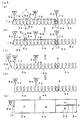
- Fig. 2 shows an example of processes for knitting the knitted fabric.
- a carriage is equipped with three cam systems S1, S2, S3. Explanation is provided to a case in which the knitting operations of the knit, the tuck and the miss and the stitch transfer are able to be done by each cam system S1, S2, S3 similarly, and the sprit knit is able to be done by at least the intermediate cam system S2.
- the cam system on the leading side is referred to S1
- the cam system on the trailing side is referred to S3, according to the running direction of the carriage.
- each area corresponding to A area 2a, B area 2b, C area 2c and D area 2d is indicated by A, B, C, and D, respectively.
- Yarn carriers used in the respective areas are also indicated by A, B, C, and D.
- Numerical numbers 1-12 on the left side of the drawing designate strokes of the carriage.
- S1, S2, S3 on the right side of the drawing designate the cam system to be used.
- the carriage moves rightwards, and the areas A, C are knitted by the cam system S1 and the area B is knitted by the cam system S2, respectively.
- the carriage moves leftwards, and the areas C, A are knitted by the cam system S1 and the area B is knitted by the cam system S2, respectively.
- the related areas are interconnected by the tuck.
- the stroke 1 and the stroke 2 are repeated to knit the areas A, B, C.
- the yarn carrier D moves leftwards, so that the knitting yarn used for the knitting of the area D is yarned in from the left side.
- the stitches are transferred from the front needle bed to the back needle bed by the cam system S1 first, then, while the split knit is provided by the cam system S2, the cross-over yarn is captured by the knitting needle on the back needle bed and is formed as a new loop and the loop is transferred to the front needle bed.
- the cam system S3 the new loop is transferred from the back needle bed to the front needle bed to form double stitches with the knitting needle on the front needle bed.
- This process involving the split knit should preferably be taken at several points according to a required distance for the yarn in, in order to ensure the capture of the cross-over yarn.
- the carriage moves from the area D to the area B and the yarn carrier D as moved to the area D in the stroke 5 is kicked back to the area B.
- the stroke 7 and the stroke 8 are repeated to knit the areas A, B, D.
- the left end of the area D shown in dashed line is formed by the miss, because it has already been knitted in the stroke 5.
- the stitches of the area D are formed including the left end shown in the dashed line.
- the carriage moves from the area B to the area D and the yarn carrier D as moved to the area B in the stroke 8 is kicked back to the area D.
- the yarn carrier D moves leftwards and the knitting yarn used for the knitting of the area D is yarned out to the left side.
- the split knit may also be taken at several points according to a required distance for the yarn out.
- the yarn carrier C moves from the right side so that the knitting yarn used for the knitting of the area C is yarned in from the right.
- Fig. 3 shows typically a stitch structure of a principal part of a knitting method of another embodiment of the present invention.
- Fig. 3(a) shows a state in which one course of stitches 11a, 11b, 11c are formed with the latch needles 10a, 10b, 10c on the front needle bed, as is the case with Fig. 1(a) .
- Fig. 3(a) shows typically a stitch structure of a principal part of a knitting method of another embodiment of the present invention.
- Fig. 3(a) shows a state in which one course of stitches 11a, 11b, 11c are formed with the latch needles 10a, 10b, 10c on the front needle bed, as is the case with Fig. 1(a) .
- Fig. 3 shows typically a stitch structure of a principal part of a knitting method of another embodiment of the present invention.
- Fig. 3(a) shows a state in which one course of stitches 11a, 11b, 11c are formed with the latch needles 10a, 10b
- FIG. 3(b) shows a state in which when the knitting yarn serving as the cross-over yarn 15 is yarned in, the split knit 23 is provided to capture the cross-over yarn 15 by the hook of the latch needle 10b serving as the holding needle and form the stitch 15a as a new loop, while also part of the held stitch is knocked over as the old loop 14a so that the stitch 14b is formed with the latch needle 13, which is the opposite, by the stitch transfer.
- Fig. 3(c) shows a state in which the stitch 14b transferred to the latch needle 13 via the split knit 23 in Fig. 3(b) is transferred back to the former latch needle 10b and is overlapped with the stitch 15a held by the latch needle 10b, to form double stitches 24.
- Fig. 3(c) shows a state in which the knitting yarn serving as the cross-over yarn 15 is yarned in, the split knit 23 is provided to capture the cross-over yarn 15 by the hook of the latch needle 10b serving as the holding needle and form the stitch 15a as a new loop,
- FIG. 3(d) shows a state in which stitches 21a, 21b, 21c in the course next to the course including the double stitches 24 are knitted.
- stitches following the stitches 21a, 21b, 21c are formed in the same manner.
- the cross - over yarn 15 shown in dashed line can be drawn out in the lateral direction 15x as viewed from the drawing and removed.
- the stitch 14a formed in Fig. 3(b) is absorbed in the surrounding stitches and is returned to the sinker loop between the former stitches 10b, 10c.
- the processes for capturing the cross - over yarn 15 can be cut to that extent, as compared with the embodiment of Fig. 1 .
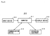
- Fig. 4 shows a schematic structure of a designing apparatus 30 which is still another embodiment of the present invention.
- the designing apparatus 30 generates knitting data required for knitting a knitted fabric by using a flatbed knitting machine provided with at least a pair of needle beds, such as a front needle bed and a back needle bed, which are arranged opposite to each other to define a needle bed gap between them, and a number of latch needles 10a, 10b, 10c, 13 used as knitting needles which are arranged on the respective needle beds.
- the designing apparatus 30 is worked out by installing knitted fabric designing software in a general - purpose computer 31.
- Various operations can be input in the computer 31 via an input device 32, and operation results and processing results can be displayed via a display device 33.
- a communication device 34 can be used for software download and data communication.
- a recording equipment 35 can be used for recording the software and data.
- the knitting data generated by the designing apparatus 30 can be fed to the flatbed knitting machine via recording media in which the data can be recorded by the communication device 34 and the recording equipment 35.
- the knitting data includes the data on the process of making the cross-over yarn 15 remaining in the knitted fabric 22, 25 by using the latch needle 10b holding the stitch 11b as the holding needle.
- the knitting yarn serving as the cross-over yarn 15 is captured and formed as a new loop 15a by the hook of the latch needle, which serves as stitch transfer side when the split knit 16, 23 is provided between the latch needle 10b serving as the holding needle and the latch needle 13 arranged opposite to the latch needle 10b across the needle bed gap 12.
- the knitting data is generated to allow the stitch hooked by the opposite needle to be transferred to and overlapped with the stitch hooked by the holding needle so that it can be remained in the knitted fabric in the form of one of the double stitches.
Landscapes
- Engineering & Computer Science (AREA)
- Textile Engineering (AREA)
- Knitting Of Fabric (AREA)
- Knitting Machines (AREA)
Applications Claiming Priority (1)
| Application Number | Priority Date | Filing Date | Title |
|---|---|---|---|
| JP2010058245A JP5436279B2 (ja) | 2010-03-15 | 2010-03-15 | 編地、およびその編成方法、ならびにデザイン装置 |
Publications (2)
| Publication Number | Publication Date |
|---|---|
| EP2369045A1 EP2369045A1 (en) | 2011-09-28 |
| EP2369045B1 true EP2369045B1 (en) | 2014-05-07 |
Family
ID=44351538
Family Applications (1)
| Application Number | Title | Priority Date | Filing Date |
|---|---|---|---|
| EP11002149.0A Active EP2369045B1 (en) | 2010-03-15 | 2011-03-15 | Knitted fabric, knitting method thereof and designing apparatus |
Country Status (3)
| Country | Link |
|---|---|
| EP (1) | EP2369045B1 (enExample) |
| JP (1) | JP5436279B2 (enExample) |
| CN (1) | CN102191614B (enExample) |
Families Citing this family (3)
| Publication number | Priority date | Publication date | Assignee | Title |
|---|---|---|---|---|
| JP5922903B2 (ja) * | 2011-10-03 | 2016-05-24 | 株式会社島精機製作所 | 編地の編成方法 |
| CN103668734B (zh) * | 2012-08-31 | 2016-06-01 | 北京大豪科技股份有限公司 | 嵌花编织方法及系统 |
| JP2015074836A (ja) | 2013-10-04 | 2015-04-20 | 株式会社島精機製作所 | 編地の編成方法 |
Family Cites Families (8)
| Publication number | Priority date | Publication date | Assignee | Title |
|---|---|---|---|---|
| US5259207A (en) * | 1989-09-28 | 1993-11-09 | Shima Seiki Mfg., Ltd. | Knitted product |
| JP3523501B2 (ja) * | 1998-09-25 | 2004-04-26 | 株式会社島精機製作所 | インレイ編地編成方法およびインレイ編地 |
| JP4002870B2 (ja) * | 2003-08-08 | 2007-11-07 | 株式会社島精機製作所 | ストライプ柄を具える筒状編地の編成方法およびストライプ柄を具える筒状編地 |
| JP4015980B2 (ja) * | 2003-09-19 | 2007-11-28 | 株式会社島精機製作所 | 横編機の端糸処理装置および方法 |
| WO2006104062A1 (ja) * | 2005-03-28 | 2006-10-05 | Shima Seiki Manufacturing Limited | 編地の編成方法 |
| JP4916508B2 (ja) * | 2006-03-20 | 2012-04-11 | 株式会社島精機製作所 | 編地の編成方法およびデザイン装置 |
| ES2354377T3 (es) * | 2007-06-15 | 2011-03-14 | H. STOLL GMBH & CO. KG | Procedimiento para ligar un principio y/o un final de un hilo de género de punto. |
| EP2333139A1 (en) * | 2008-08-08 | 2011-06-15 | Shima Seiki Mfg., Ltd | Method of knitting tubular knitted fabric, and tubular knitted fabric |
-
2010
- 2010-03-15 JP JP2010058245A patent/JP5436279B2/ja active Active
-
2011
- 2011-03-15 EP EP11002149.0A patent/EP2369045B1/en active Active
- 2011-03-15 CN CN201110064134.6A patent/CN102191614B/zh active Active
Also Published As
| Publication number | Publication date |
|---|---|
| CN102191614B (zh) | 2014-12-03 |
| JP5436279B2 (ja) | 2014-03-05 |
| EP2369045A1 (en) | 2011-09-28 |
| JP2011190555A (ja) | 2011-09-29 |
| CN102191614A (zh) | 2011-09-21 |
Similar Documents
| Publication | Publication Date | Title |
|---|---|---|
| EP1995363B1 (en) | Method for knitting fabric and design device | |
| EP2565308B1 (en) | Joining method of neighboring knitted fabric pieces, and knitted fabric | |
| EP2390393A1 (en) | Method for preventing ravel of knitting yarn and knitted fabric | |
| EP2423362B1 (en) | Set up method of knitted fabric | |
| EP1728908A1 (en) | Knitting method for wide rib texture by plating | |
| EP2568066B1 (en) | Set-up method of knitted fabric | |
| EP2369045B1 (en) | Knitted fabric, knitting method thereof and designing apparatus | |
| US6578389B1 (en) | Knitting method for disposing unused yarn edge | |
| EP2290141B1 (en) | Method of knitting a tubular fabric and tubular fabric | |
| EP2327818B1 (en) | Knitting method of knitted fabric, and knitted fabric | |
| EP2455521B1 (en) | Set-up method of knitted fabric | |
| EP2546399B1 (en) | Set-up method of knitted fabric and knitted fabric | |
| EP2154280A1 (en) | Fabric having yarn-finished portion, treating method therefor, and design device | |
| JP2010053490A (ja) | 筒状編地の編成方法と編地 | |
| JPH09217254A (ja) | 渡り糸止め部の形成方法 | |
| US5819558A (en) | Method of lowering the yarn height for knitting single knit fabric | |
| KR20220079449A (ko) | 편성방법 | |
| EP2636778B1 (en) | Method for preventing unraveling of knitting yarn | |
| EP2354284A1 (en) | Plating knitting method | |
| EP2397588B1 (en) | Inner widening method | |
| JP2008303489A (ja) | 編地の編成方法および編地 | |
| JP2013256723A (ja) | 編地の解れ止め方法 | |
| CN114657685A (zh) | 用于横机或编织机的针织系统 | |
| JP2024034119A (ja) | 編地の編成方法 | |
| JPH0931802A (ja) | 多色シングル編地の編成方法 |
Legal Events
| Date | Code | Title | Description |
|---|---|---|---|
| PUAI | Public reference made under article 153(3) epc to a published international application that has entered the european phase |
Free format text: ORIGINAL CODE: 0009012 |
|
| AK | Designated contracting states |
Kind code of ref document: A1 Designated state(s): AL AT BE BG CH CY CZ DE DK EE ES FI FR GB GR HR HU IE IS IT LI LT LU LV MC MK MT NL NO PL PT RO RS SE SI SK SM TR |
|
| AX | Request for extension of the european patent |
Extension state: BA ME |
|
| 17P | Request for examination filed |
Effective date: 20120328 |
|
| GRAP | Despatch of communication of intention to grant a patent |
Free format text: ORIGINAL CODE: EPIDOSNIGR1 |
|
| INTG | Intention to grant announced |
Effective date: 20131119 |
|
| GRAS | Grant fee paid |
Free format text: ORIGINAL CODE: EPIDOSNIGR3 |
|
| GRAA | (expected) grant |
Free format text: ORIGINAL CODE: 0009210 |
|
| AK | Designated contracting states |
Kind code of ref document: B1 Designated state(s): AL AT BE BG CH CY CZ DE DK EE ES FI FR GB GR HR HU IE IS IT LI LT LU LV MC MK MT NL NO PL PT RO RS SE SI SK SM TR |
|
| REG | Reference to a national code |
Ref country code: GB Ref legal event code: FG4D |
|
| REG | Reference to a national code |
Ref country code: AT Ref legal event code: REF Ref document number: 666794 Country of ref document: AT Kind code of ref document: T Effective date: 20140515 |
|
| REG | Reference to a national code |
Ref country code: IE Ref legal event code: FG4D |
|
| REG | Reference to a national code |
Ref country code: DE Ref legal event code: R096 Ref document number: 602011006639 Country of ref document: DE Effective date: 20140618 |
|
| REG | Reference to a national code |
Ref country code: AT Ref legal event code: MK05 Ref document number: 666794 Country of ref document: AT Kind code of ref document: T Effective date: 20140507 |
|
| REG | Reference to a national code |
Ref country code: NL Ref legal event code: VDEP Effective date: 20140507 |
|
| REG | Reference to a national code |
Ref country code: LT Ref legal event code: MG4D |
|
| PG25 | Lapsed in a contracting state [announced via postgrant information from national office to epo] |
Ref country code: FI Free format text: LAPSE BECAUSE OF FAILURE TO SUBMIT A TRANSLATION OF THE DESCRIPTION OR TO PAY THE FEE WITHIN THE PRESCRIBED TIME-LIMIT Effective date: 20140507 Ref country code: CY Free format text: LAPSE BECAUSE OF FAILURE TO SUBMIT A TRANSLATION OF THE DESCRIPTION OR TO PAY THE FEE WITHIN THE PRESCRIBED TIME-LIMIT Effective date: 20140507 Ref country code: NO Free format text: LAPSE BECAUSE OF FAILURE TO SUBMIT A TRANSLATION OF THE DESCRIPTION OR TO PAY THE FEE WITHIN THE PRESCRIBED TIME-LIMIT Effective date: 20140807 Ref country code: IS Free format text: LAPSE BECAUSE OF FAILURE TO SUBMIT A TRANSLATION OF THE DESCRIPTION OR TO PAY THE FEE WITHIN THE PRESCRIBED TIME-LIMIT Effective date: 20140907 Ref country code: LT Free format text: LAPSE BECAUSE OF FAILURE TO SUBMIT A TRANSLATION OF THE DESCRIPTION OR TO PAY THE FEE WITHIN THE PRESCRIBED TIME-LIMIT Effective date: 20140507 Ref country code: GR Free format text: LAPSE BECAUSE OF FAILURE TO SUBMIT A TRANSLATION OF THE DESCRIPTION OR TO PAY THE FEE WITHIN THE PRESCRIBED TIME-LIMIT Effective date: 20140808 |
|
| PG25 | Lapsed in a contracting state [announced via postgrant information from national office to epo] |
Ref country code: AT Free format text: LAPSE BECAUSE OF FAILURE TO SUBMIT A TRANSLATION OF THE DESCRIPTION OR TO PAY THE FEE WITHIN THE PRESCRIBED TIME-LIMIT Effective date: 20140507 Ref country code: SE Free format text: LAPSE BECAUSE OF FAILURE TO SUBMIT A TRANSLATION OF THE DESCRIPTION OR TO PAY THE FEE WITHIN THE PRESCRIBED TIME-LIMIT Effective date: 20140507 Ref country code: ES Free format text: LAPSE BECAUSE OF FAILURE TO SUBMIT A TRANSLATION OF THE DESCRIPTION OR TO PAY THE FEE WITHIN THE PRESCRIBED TIME-LIMIT Effective date: 20140507 Ref country code: LV Free format text: LAPSE BECAUSE OF FAILURE TO SUBMIT A TRANSLATION OF THE DESCRIPTION OR TO PAY THE FEE WITHIN THE PRESCRIBED TIME-LIMIT Effective date: 20140507 Ref country code: PL Free format text: LAPSE BECAUSE OF FAILURE TO SUBMIT A TRANSLATION OF THE DESCRIPTION OR TO PAY THE FEE WITHIN THE PRESCRIBED TIME-LIMIT Effective date: 20140507 Ref country code: HR Free format text: LAPSE BECAUSE OF FAILURE TO SUBMIT A TRANSLATION OF THE DESCRIPTION OR TO PAY THE FEE WITHIN THE PRESCRIBED TIME-LIMIT Effective date: 20140507 Ref country code: RS Free format text: LAPSE BECAUSE OF FAILURE TO SUBMIT A TRANSLATION OF THE DESCRIPTION OR TO PAY THE FEE WITHIN THE PRESCRIBED TIME-LIMIT Effective date: 20140507 |
|
| PG25 | Lapsed in a contracting state [announced via postgrant information from national office to epo] |
Ref country code: PT Free format text: LAPSE BECAUSE OF FAILURE TO SUBMIT A TRANSLATION OF THE DESCRIPTION OR TO PAY THE FEE WITHIN THE PRESCRIBED TIME-LIMIT Effective date: 20140908 |
|
| PG25 | Lapsed in a contracting state [announced via postgrant information from national office to epo] |
Ref country code: RO Free format text: LAPSE BECAUSE OF FAILURE TO SUBMIT A TRANSLATION OF THE DESCRIPTION OR TO PAY THE FEE WITHIN THE PRESCRIBED TIME-LIMIT Effective date: 20140507 Ref country code: EE Free format text: LAPSE BECAUSE OF FAILURE TO SUBMIT A TRANSLATION OF THE DESCRIPTION OR TO PAY THE FEE WITHIN THE PRESCRIBED TIME-LIMIT Effective date: 20140507 Ref country code: DK Free format text: LAPSE BECAUSE OF FAILURE TO SUBMIT A TRANSLATION OF THE DESCRIPTION OR TO PAY THE FEE WITHIN THE PRESCRIBED TIME-LIMIT Effective date: 20140507 Ref country code: BE Free format text: LAPSE BECAUSE OF FAILURE TO SUBMIT A TRANSLATION OF THE DESCRIPTION OR TO PAY THE FEE WITHIN THE PRESCRIBED TIME-LIMIT Effective date: 20140507 Ref country code: SK Free format text: LAPSE BECAUSE OF FAILURE TO SUBMIT A TRANSLATION OF THE DESCRIPTION OR TO PAY THE FEE WITHIN THE PRESCRIBED TIME-LIMIT Effective date: 20140507 Ref country code: CZ Free format text: LAPSE BECAUSE OF FAILURE TO SUBMIT A TRANSLATION OF THE DESCRIPTION OR TO PAY THE FEE WITHIN THE PRESCRIBED TIME-LIMIT Effective date: 20140507 |
|
| REG | Reference to a national code |
Ref country code: DE Ref legal event code: R097 Ref document number: 602011006639 Country of ref document: DE |
|
| PG25 | Lapsed in a contracting state [announced via postgrant information from national office to epo] |
Ref country code: NL Free format text: LAPSE BECAUSE OF FAILURE TO SUBMIT A TRANSLATION OF THE DESCRIPTION OR TO PAY THE FEE WITHIN THE PRESCRIBED TIME-LIMIT Effective date: 20140507 |
|
| PLBE | No opposition filed within time limit |
Free format text: ORIGINAL CODE: 0009261 |
|
| STAA | Information on the status of an ep patent application or granted ep patent |
Free format text: STATUS: NO OPPOSITION FILED WITHIN TIME LIMIT |
|
| 26N | No opposition filed |
Effective date: 20150210 |
|
| REG | Reference to a national code |
Ref country code: DE Ref legal event code: R097 Ref document number: 602011006639 Country of ref document: DE Effective date: 20150210 |
|
| PG25 | Lapsed in a contracting state [announced via postgrant information from national office to epo] |
Ref country code: SI Free format text: LAPSE BECAUSE OF FAILURE TO SUBMIT A TRANSLATION OF THE DESCRIPTION OR TO PAY THE FEE WITHIN THE PRESCRIBED TIME-LIMIT Effective date: 20140507 |
|
| PG25 | Lapsed in a contracting state [announced via postgrant information from national office to epo] |
Ref country code: MC Free format text: LAPSE BECAUSE OF FAILURE TO SUBMIT A TRANSLATION OF THE DESCRIPTION OR TO PAY THE FEE WITHIN THE PRESCRIBED TIME-LIMIT Effective date: 20140507 Ref country code: LU Free format text: LAPSE BECAUSE OF FAILURE TO SUBMIT A TRANSLATION OF THE DESCRIPTION OR TO PAY THE FEE WITHIN THE PRESCRIBED TIME-LIMIT Effective date: 20150315 |
|
| REG | Reference to a national code |
Ref country code: CH Ref legal event code: PL |
|
| GBPC | Gb: european patent ceased through non-payment of renewal fee |
Effective date: 20150315 |
|
| REG | Reference to a national code |
Ref country code: FR Ref legal event code: ST Effective date: 20151130 |
|
| REG | Reference to a national code |
Ref country code: IE Ref legal event code: MM4A |
|
| PG25 | Lapsed in a contracting state [announced via postgrant information from national office to epo] |
Ref country code: IE Free format text: LAPSE BECAUSE OF NON-PAYMENT OF DUE FEES Effective date: 20150315 Ref country code: LI Free format text: LAPSE BECAUSE OF NON-PAYMENT OF DUE FEES Effective date: 20150331 Ref country code: CH Free format text: LAPSE BECAUSE OF NON-PAYMENT OF DUE FEES Effective date: 20150331 Ref country code: GB Free format text: LAPSE BECAUSE OF NON-PAYMENT OF DUE FEES Effective date: 20150315 |
|
| PG25 | Lapsed in a contracting state [announced via postgrant information from national office to epo] |
Ref country code: FR Free format text: LAPSE BECAUSE OF NON-PAYMENT OF DUE FEES Effective date: 20150331 |
|
| PG25 | Lapsed in a contracting state [announced via postgrant information from national office to epo] |
Ref country code: MT Free format text: LAPSE BECAUSE OF FAILURE TO SUBMIT A TRANSLATION OF THE DESCRIPTION OR TO PAY THE FEE WITHIN THE PRESCRIBED TIME-LIMIT Effective date: 20140507 |
|
| PG25 | Lapsed in a contracting state [announced via postgrant information from national office to epo] |
Ref country code: SM Free format text: LAPSE BECAUSE OF FAILURE TO SUBMIT A TRANSLATION OF THE DESCRIPTION OR TO PAY THE FEE WITHIN THE PRESCRIBED TIME-LIMIT Effective date: 20140507 Ref country code: HU Free format text: LAPSE BECAUSE OF FAILURE TO SUBMIT A TRANSLATION OF THE DESCRIPTION OR TO PAY THE FEE WITHIN THE PRESCRIBED TIME-LIMIT; INVALID AB INITIO Effective date: 20110315 Ref country code: BG Free format text: LAPSE BECAUSE OF FAILURE TO SUBMIT A TRANSLATION OF THE DESCRIPTION OR TO PAY THE FEE WITHIN THE PRESCRIBED TIME-LIMIT Effective date: 20140507 |
|
| PG25 | Lapsed in a contracting state [announced via postgrant information from national office to epo] |
Ref country code: TR Free format text: LAPSE BECAUSE OF FAILURE TO SUBMIT A TRANSLATION OF THE DESCRIPTION OR TO PAY THE FEE WITHIN THE PRESCRIBED TIME-LIMIT Effective date: 20140507 |
|
| PG25 | Lapsed in a contracting state [announced via postgrant information from national office to epo] |
Ref country code: MK Free format text: LAPSE BECAUSE OF FAILURE TO SUBMIT A TRANSLATION OF THE DESCRIPTION OR TO PAY THE FEE WITHIN THE PRESCRIBED TIME-LIMIT Effective date: 20140507 |
|
| PG25 | Lapsed in a contracting state [announced via postgrant information from national office to epo] |
Ref country code: AL Free format text: LAPSE BECAUSE OF FAILURE TO SUBMIT A TRANSLATION OF THE DESCRIPTION OR TO PAY THE FEE WITHIN THE PRESCRIBED TIME-LIMIT Effective date: 20140507 |
|
| PGFP | Annual fee paid to national office [announced via postgrant information from national office to epo] |
Ref country code: DE Payment date: 20241231 Year of fee payment: 15 |
|
| PGFP | Annual fee paid to national office [announced via postgrant information from national office to epo] |
Ref country code: IT Payment date: 20250211 Year of fee payment: 15 |