EP2367037B1 - Optical cable with controlled fiber positioning - Google Patents
Optical cable with controlled fiber positioning Download PDFInfo
- Publication number
- EP2367037B1 EP2367037B1 EP11158852.1A EP11158852A EP2367037B1 EP 2367037 B1 EP2367037 B1 EP 2367037B1 EP 11158852 A EP11158852 A EP 11158852A EP 2367037 B1 EP2367037 B1 EP 2367037B1
- Authority
- EP
- European Patent Office
- Prior art keywords
- cable
- slot
- fiber optic
- channel
- axis
- Prior art date
- Legal status (The legal status is an assumption and is not a legal conclusion. Google has not performed a legal analysis and makes no representation as to the accuracy of the status listed.)
- Active
Links
- 239000000835 fiber Substances 0.000 title claims description 55
- 230000003287 optical effect Effects 0.000 title description 8
- 239000013307 optical fiber Substances 0.000 claims description 82
- 239000004020 conductor Substances 0.000 claims description 53
- 229920000642 polymer Polymers 0.000 claims description 12
- 239000000463 material Substances 0.000 description 15
- 239000013536 elastomeric material Substances 0.000 description 13
- 238000005452 bending Methods 0.000 description 7
- 229920002725 thermoplastic elastomer Polymers 0.000 description 7
- 229920002803 thermoplastic polyurethane Polymers 0.000 description 6
- 239000011810 insulating material Substances 0.000 description 4
- 238000000034 method Methods 0.000 description 4
- 230000002093 peripheral effect Effects 0.000 description 4
- 239000004800 polyvinyl chloride Substances 0.000 description 3
- 239000004760 aramid Substances 0.000 description 2
- 229920003235 aromatic polyamide Polymers 0.000 description 2
- 239000002131 composite material Substances 0.000 description 2
- 239000000654 additive Substances 0.000 description 1
- 230000002411 adverse Effects 0.000 description 1
- 150000001875 compounds Chemical class 0.000 description 1
- 238000010276 construction Methods 0.000 description 1
- 238000005336 cracking Methods 0.000 description 1
- 239000003063 flame retardant Substances 0.000 description 1
- 230000001788 irregular Effects 0.000 description 1
- 230000014759 maintenance of location Effects 0.000 description 1
- 239000000203 mixture Substances 0.000 description 1
- 229920005989 resin Polymers 0.000 description 1
- 239000011347 resin Substances 0.000 description 1
Images


Classifications
-
- G—PHYSICS
- G02—OPTICS
- G02B—OPTICAL ELEMENTS, SYSTEMS OR APPARATUS
- G02B6/00—Light guides; Structural details of arrangements comprising light guides and other optical elements, e.g. couplings
- G02B6/44—Mechanical structures for providing tensile strength and external protection for fibres, e.g. optical transmission cables
- G02B6/4401—Optical cables
- G02B6/4415—Cables for special applications
- G02B6/4416—Heterogeneous cables
-
- G—PHYSICS
- G02—OPTICS
- G02B—OPTICAL ELEMENTS, SYSTEMS OR APPARATUS
- G02B6/00—Light guides; Structural details of arrangements comprising light guides and other optical elements, e.g. couplings
- G02B6/44—Mechanical structures for providing tensile strength and external protection for fibres, e.g. optical transmission cables
- G02B6/4401—Optical cables
- G02B6/4407—Optical cables with internal fluted support member
-
- G—PHYSICS
- G02—OPTICS
- G02B—OPTICAL ELEMENTS, SYSTEMS OR APPARATUS
- G02B6/00—Light guides; Structural details of arrangements comprising light guides and other optical elements, e.g. couplings
- G02B6/44—Mechanical structures for providing tensile strength and external protection for fibres, e.g. optical transmission cables
- G02B6/4401—Optical cables
- G02B6/4429—Means specially adapted for strengthening or protecting the cables
- G02B6/443—Protective covering
- G02B6/4432—Protective covering with fibre reinforcements
-
- H—ELECTRICITY
- H01—ELECTRIC ELEMENTS
- H01B—CABLES; CONDUCTORS; INSULATORS; SELECTION OF MATERIALS FOR THEIR CONDUCTIVE, INSULATING OR DIELECTRIC PROPERTIES
- H01B11/00—Communication cables or conductors
- H01B11/22—Cables including at least one electrical conductor together with optical fibres
Definitions
- the present disclosure generally relates to fiber optic cables and methods of controlling a position of an optical fiber within the fiber optic cable.
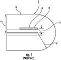
- FIG. 1 shows a typical fiber optic cable in a bent back configuration.
- the fiber optic cable 2 is generally circular and has an outer bend periphery 16 and a cable diameter or thickness 6. Internal to the cable is an optical fiber 10, which carries data.
- a bend radius 8 is at a minimum and is approximately equal to the cable diameter 6.
- the location of the optical fiber 10 within the cable 2 will affect a bend radius 12 of the optical fiber 10. If the optical fiber 10 is close to the outer bend periphery 16, the fiber will have a larger bend radius and experience lower attenuation.
- the bend radius of the fiber will be smaller and cause greater delta attenuation due bending. If the bend radius 12 is small enough, the optical fiber may crack at an outer surface 18 of the optical fiber 10 and cause cracking or fracture of the optical fiber 10.
- US 2004/057681 A1 relates to a high strength fiber optic cable comprising a at least one optical fiber component being disposed within a retention area of the optic cable.
- US 2008/0118211 A1 relates to a fiber optic cable, wherein at least one optical waveguide and a dry insert are are disposed in a cavity in the fiber optic cable.
- GB 2123164 A is directed to a composite cable construction comprising a longitudinal former having along its length a plurality of groves, wherein the grooves may accommodate alternately an optical fiber element and an electrically conductive cable element.
- DE 2928678 A1 is directed to an optical cable comprising an inner body having a plurality of cavities to support optical waveguides.
- JP 2001/250427 A relates to a composite cable comprising insulated wire cores being embedded in a cable jacket in which a conduit for guiding an optical fiber is arranged.
- US 2007/098342 A1 relates to a distribution fiber optic cable comprising a cable core with cavities for housing optical fibers, wherein strength members are disposed on opposite sites of the cavities.
- the fiber optic cable comprises a polymer jacket having a channel therein, the channel having a first slot, at least one optical fiber in the first slot, a first electrical conductor, and a second electrical conductor.
- the first slot is arranged on a first axis, and a second axis extends through the first and second electrical conductors.
- the first electrical conductor is located on a first side of the first slot and the second electrical conductor is located on an opposite side of the first slot.
- the cable has a preferential bend axis of minimum bend moment of inertia about the second axis.
- the optical fiber is positioned in the first slot and remains within the first slot when the fiber optic cable is bent a maximum amount such that a bend radius of the optical fiber is greater than or equal to a minimum bend radius of the optical fiber.
- the first and second electrical conductors are located in a second slot aligned with the second axis and intersecting the first slot, the first and second slots being defined in part by four projections of the cable jacket extending inwardly toward a geometric center of the cable.
- the cable may have first and second preferential bend axes such that when the cable is bent back about either axis, the optical fibers are bent at bend radii exceeding their minimum bend radii.
- the cable can have a round cross-section with a diameter in the range of 2.8-3.2 millimeters, and the geometric center of the first slot can be within 0.2 millimeters of the geometric center of the cable.
- the fiber optic cables described herein may include a plurality of optical fibers arranged with little or no stranding or twisting around each other.
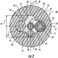
- FIG. 2 is a cross-sectional view of a fiber optic cable 30 according to a first embodiment of this disclosure.
- the cable 30 includes a polymer jacket 32 having an outer periphery 34 and a channel periphery 36 with the channel periphery 36 defining a channel 38.
- the cross-section of the cable 30 is generally circular with a diameter of about 3.0 millimeters (mm).
- mm millimeters
- references to diameters and radii of circular cables refer to median or average values.
- polymer and “polymeric” indicate materials comprised primarily of polymers, but allow for the inclusion of non-polymer additives and other materials, such as fire-retardant compounds, etc., and the inclusion of multiple polymers in a blend.
- the polymer jacket 32 encloses the channel 38 and the channel 38 may extend the entire length of the cable 30.
- the cable 30 further includes a pair of metallic electrical conductors 40, 42 that supply power to peripheral electrical equipment.
- the electrical conductors 40, 42 can in addition or alternatively carry data.
- the electrical conductors 40, 42 may be surrounded by insulating material 44, 46 respectively.
- the electrical conductors 40, 42 can be embedded in the jacket 32 so that insulating material can be omitted.
- Data-carrying optical fibers 48, 50 are also included within the cable 30.
- the optical fibers 48, 50 may be surrounded by buffer layers 58, 60, respectively.
- the electrical conductors 40, 42 and the buffered optical fibers 48, 50 are positioned within the channel 38. Additional conductors can be wholly or partially embedded within the jacket 32.
- the optical fibers 48, 50 are generally allowed to translate within the channel 38 when the cable 30 is bent.
- the optical fibers 48, 50 can translate in the channel 38 along a first axis 52 that is perpendicular to a first axis 54 along which the electrical conductors 40, 42 are generally aligned.
- the channel 38 has a "height" or length dimension 56 along the axis 52 through which the fibers can translate.
- the channel 38 is "cross" or "T” shaped, and the cable 30 has a geometric center 62 generally located at the intersection of the axes 52, 54.
- the optical fibers 40, 42 are arranged in a first slot 72, which is aligned with the axis 52, and the electrical conductors 40, 42 are arranged in a second slot 74, which is aligned with to the axis 54.
- the slots 72, 74 arc defined in part by four projections 76 that extend radially inward into the channel 38.
- the projections 76 may have the form of rounded corners.
- the shape of the slots 72, 74 and the location of the electrical conductors 40, 42 provide some degree of a preferential bend characteristic to the cable 30 to bend either about the axis 52 or the axis 54, as well as allowing the optical fibers 48, 50 to translate to locations to increase their bend radius and reduce optical attenuation.
- the shape of the channel 38 minimizes the material moments of inertia about the axis 54, and accordingly generally induces the cable 30 to bend about axis 54 when the cable 30 is subjected to bending moments. If the cable 30 is bent back about the axis 54, the optical fibers 48, 50 will undergo a bend radius approximately equal to or greater than the cable radius 64.
- the optical fibers can be selected so that when the cable is bent back about the axis 54, which is aligned with the slot 72, the optical fibers do not experience undue optical attenuation.
- the optical fibers 48, 50 may have a minimum bend radius of about 1.5 mm that results in an acceptable delta attenuation in the range of about 1.5 dB to 2.0 dB.
- the exemplary cable radius 64, corresponding to the bend back radius, is about 1.5 mm, so that the optical fibers 48, 50 are not bent at a radius smaller than their minimum bend radius when bending about axis 54.
- the optical fibers are allowed to translate in the slot 72 so that the fibers 48, 50 do not bend at a radius below their minimum bend radius. For example, if the cable 30 is bent back about axis 54 so that a location 66 on the cable 30 is where the cable is bent back upon itself, the optical fibers will translate "downwardly" in the slot 72, away from the bend back location 66, to the orientation shown in FIG. 2 . The optical fiber 48 will move away from location 66, toward the "bottom" of the slot 72, where the fiber 48 is at its lowest strain state. The optical fiber 50 will also move away from the bend back location 66 toward a state of low strain.
- the height 56 of the slot 72 is selected so that optical fibers in the slot do not bend at a radius below their minimum bend radius.
- the height 56 of the slot 72 in the exemplary embodiment is about 1.5 mm, so that when the cable 30 is in bend back, the optical fiber closest to the bend back location is bent at a radius of at least 1.5 mm.
- the preferential bend characteristic of the cable 30 prevents the optical fibers 48, 50 in the cable 30 from bending below their minimum bend radii.
- the electrical conductors 40, 42 are constrained within the slot 74 to prevent crossover with the optical fibers 48, 50, which reduces the likelihood of the fibers from moving out of their slot 72.
- a geometric center of the slot 72 can correspond to the geometric center 62 of the cable 30, which can have a round cross-section, or the geometric center of the slot 72 can be within 0.2 mm of the center of the cable 30.
- the illustrated optical fibers 48, 50 include buffer layers 58, 60, buffer layers are not required for the optical fibers illustrated in this specification.
- a cable 30 as shown in FIG. 2 has a diameter in the range of 2.8-3.2 mm, a slot 72 having a dimension 56 in the range of 1.2-1.8 mm, and two electrical conductors in the range of 24 to 28 AWG (American wire gauge).
- the electrical conductors 40, 42 are located on opposite sides of the slot 72, and their centerlines are spaced from one another a distance in the range of 1.2 to 1.75 mm.
- the cable jacket 102 is comprised primarily of thermoplastic urethane (TPU), thermoplastic elastomer (TPE), or polyvinyl chloride (PVC).
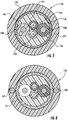
- FIG. 3 is a schematic cross-sectional view of a fiber optic cable 100 according to another embodiment of this disclosure, which is not covered by the claims.
- the cable 100 includes a polymer jacket 102 having an outer periphery 104 and a channel periphery 106 with the channel periphery 106 defining a channel 124.
- a cross-section of the illustrated cable 100 is generally circular and has a diameter of less than about 3.0 millimeters (mm).
- the jacket 102 surrounds the channel 124 and the channel 124 may extend the entire length of the cable 100.
- the cable 100 further includes a plurality of electrical conductors 108, 110 that may supply power to peripheral equipment.
- the electrical conductors 108, 110 are each surrounded by an insulating material 112, 114 respectively, although the insulating material may be omitted in some embodiments.
- the conductors 108, 110 can be wholly or partially embedded in the jacket 102 at each end of the channel 124.
- Data-carrying buffered optical fibers 116, 118 are also included within the cable 100, disposed between the electrical conductors 108, 100.
- the optical fibers 116, 118 are also each surrounded by buffer layers 120, 122, respectively.
- the electrical conductors 108, 110 and the buffered optical fibers 116, 118 are positioned within the channel 124.
- the optical fibers 116, 118 are generally allowed to translate within the channel 124, between the conductors 108, 110, when the cable 100 is bent.
- the channel 124 has the shape of a slot extending along a first axis 126, which is perpendicular to a second axis 128.
- the cable 100 further includes a strength material 130, such as an aramid yarn.
- the strength material 130 is arranged within the channel 124. In accordance with the embodiment and as shown in FIG. 3 , the strength material 130 surrounds the optical fibers 116, 118 and electrical conductors 108, 110 .
- the strength material 130 may be generally located throughout the channel 124 and dispersed among the electrical conductors 108, 110 and the optical fibers 116, 118.
- the strength material 130 is loosely packed enough such that it allows the optical fibers 116, 118 to move to a limited extent within the jacket 102.
- the channel or slot 124 can have a maximum height 132 and a maximum width 134.
- the width 134 can be, for example, at least two, or even three times the height 132.
- the shape of the channel 124 provides the cable 100 with a preferential bend characteristic that causes the cable 30 to bend about the axis 126 when experiencing bending stresses.
- the non-preferred direction of bending is about the second axis 128.
- the optical fibers 48, 50 are selected so that as cable 100 bends back on itself about axis 126, the optical fibers do not bend at a radius below their minimum bend radii.
- the exemplary cable 100 has an outer diameter of about 3.0 mm or less (i.e. the radius 132 being 1.5 mm or less).
- the optical fibers 116, 118 have a minimum bend radius of about 1.2 mm. Therefore, as the cable 100 is bent back on itself about axis 126 (i.e. the preferred direction about the axis having the minimum moment of inertia), the optical fibers 116, 118 will not have a bend radius below their minimum bend radius.
- the cable 100 is bent about axis 128 (i.e. the non-preferred direction and the axis having the maximum moment of inertia), it is possible that one of the optical fibers 116, 118 may be bent at a radius below its minimum bend radius.
- a length of the cable 100 is bent about the axis having the maximum moment of inertia, the cable 100 tends to rotate about 90 degrees to align the axis having the minimum moment of inertia with the axis about which the cable 100 is bent. For example, if the length of cable 100 is bent at location 135, stripes 136, 137 on the exterior of the cable 100 are seen to rotate about 90 degrees.
- a ratio of the bend energy required to bend the cable 100 about the axis 128 having the maximum moment of inertia to the bend energy required to bend the cable 100 about the axis 126 having the minimum moment of inertia should be at least 1.5:1 and may be as large as 4:1.
- Bend energy and inertia depend on the cross-sectional geometry of the cable as well as the material properties of the individual cables (for example, the cable jacket, the electrical conductors, and the optical fibers to name but a few) and can be calculated readily.
- the shape of the channel 124, or optical fiber channel 124 can be determined based on the inertia and bend energy calculations to ensure the optical fibers 116, 118 are not bent at a radius less than their minimum bend radius.
- a geometric center of the channel 124 can correspond to a geometric center of the cable 100, which can have a round cross-section, or the geometric center of the channel 124 can be within 0.2 mm of the center of the cable 100.
- a cable 100 as shown in FIG. 3 has a diameter in the range of 2.8-3.2 mm, a channel 124 having a height 132 in the range of 0.6-1.4 mm, a width 134 in the range of 1.5-2.8 mm, and two electrical conductors in the range of 24 to 28 AWG.
- the electrical conductors 40, 42 are located on opposite sides of the optical fibers 116, 118.
- the cable jacket 102 is comprised primarily of thermoplastic urethane (TPU), thermoplastic elastomer (TPE), or polyvinylchloride (PVC).
- FIG. 5 is a cross-sectional view of a fiber optic cable 140 according to another embodiment of this disclosure, which is not covered by the claims.
- the cable 140 includes a polymer jacket 141 having an outer periphery 142 and a channel periphery 144 that defines a channel or optical channel 145.
- a cross-section of the cable 140 is generally circular with a diameter of 3.0 millimeters or less, or more generally in the range of 2.8-3.2 mm.
- the jacket 141 surrounds the channel 145 and the channel 145 may extend the entire length of the cable 140.
- the cable 140 further includes a plurality of electrical conductors 148, 150 that supply power to peripheral equipment. Data-carrying buffered optical fibers 152, 154 arc also included within the cable 140.
- the electrical conductors 148, 150 and the optical fibers 152, 154 are positioned within the channel 145.
- the electrical conductors 152, 154 may be wholly or partially embedded within the jacket 141, between the outer periphery 142 and the channel periphery 144.
- the cable 140 further includes a strength material 146, such as an aramid yarn. As illustrated, the strength material 146 is arranged within the jacket 141 and adjacent to channel periphery 144. It is not required that the strength material 146 be arranged as such and may be arranged within the jacket in any convenient orientation or arrangement.
- the cable 140 also includes a non-conducting elastomeric material 156 that occupies the channel 145.
- a conductive elastomeric material may be used if necessary to provide EMI (electromagnetic interference) shielding or for other properties.
- the elastomeric material 156 functions to maintain the position of the electrical conductors 148, 150 and the optical fibers 152, 152.
- the elastomeric material 156 may be any material such a polymer or resin that is sufficiently strong to maintain the position of the cable components (i.e. electrical conductors and optical fibers) and that is sufficiently flexible to allow the cable 140 to move through a wide range of motion. It is also desired that the elastomeric material 156 have a low coefficient of thermal expansion to minimize buckling.
- the elastomeric material 156 can be used to position the optical fibers 152, 154 central to the fiber optic cable 140. By doing so, the bend radius of the optical fibers 152, 154 is fixed and independent of how the
- the elastomeric material 156 can be introduced into the channel 145 by a coextrusion process as the jacket 141 is being extruded.
- the optical fibers 152, 154, and electrical conductors, if present in the channel 145, can essentially become embedded in the elastomeric material 156.
- the jacket 141 can have a modulus of elasticity in the range of 1 to 2,500 MPa.
- the elastomeric material 156 can have a modulus of elasticity in the range of 3,000 to 10,000 MPa.
- a cable 140 as shown in FIG. 5 has a diameter in the range of 2.8-3.2 mm and two electrical conductors in the range of 24-28 AWG.
- the cable jacket 102 is comprised primarily of thermoplastic urethane (TPU), thermoplastic elastomer (TPE), or polyvinylchloride (PVC) having a modulus of elasticity of less than 2,500 MPa.
- the elastomeric material 156 is a thermoplastic elastomer having EMI shielding properties, and a modulus of elasticity in the range of 3,000 to 10,000 MPa that is coextruded with the jacket 141. Elastomeric material not having EMI shielding properties has a modulus of elasticity of less than 500 MPa.
- FIGS. 6 , 7, and 8 illustrate various embodiments based on the principles of the embodiment of FIG. 5 .
- the embodiments of the cables shown in Figures 6 , 7 and 8 are not covered by the claims.
- FIG. 6 illustrates a fiber optic cable 140' having all of the elements of the fiber optic cable 140 of FIG. 5 , but includes additional data-carrying components 160, 162 arranged within the jacket 141' of the cable 140'.
- Such a configuration is known as a backward compatible fiber optic USB cable 140'.
- FIG. 7 illustrates a fiber optic cable 170 similar to the embodiment of FIG. 6 but having a different internal arrangement of the fiber optic cable components.
- the fiber optic cable 170 comprises a jacket 172 having an outer periphery 173 and a channel periphery 175, the channel periphery 175 defining a channel 190.
- Electrical conductors 176, 178 and optical fibers 182, 184 are held in position by an elastomeric material 190.
- Data-carrying conductors 186, 188 may be arranged within the jacket 172.
- a strength material 174 is arranged adjacent the channel periphery 175.
- the optical fibers 182, 184 and the electrical conductors 176, 178 are arranged central to the cable 170 to produce a smaller optical fiber channel 175.
- FIG. 8 illustrates a fiber optic cable 200 similar to the embodiment of FIG. 7 but having a different internal arrangement of the fiber optic cable components.
- the fiber optic cable 200 comprises a jacket 201 having an outer periphery 202 and a channel periphery 204, the channel periphery 204 defining a channel 205.
- Electrical conductors 206, 208, data-carrying conductors 210, 212, and optical fibers 214, 216 and are held in position by an elastomeric material 218.
- a strength material 220 is arranged adjacent the channel periphery 204.
- the optical fibers 214, 216 are arranged proximate a center of the cable 200 and the electrical conductors 206, 208 and the data-carrying conductors 210, 212 surround the optical fibers 214, 216 to produce a larger optical fiber channel 204.
Landscapes
- Physics & Mathematics (AREA)
- General Physics & Mathematics (AREA)
- Optics & Photonics (AREA)
- Communication Cables (AREA)
- Light Guides In General And Applications Therefor (AREA)
Applications Claiming Priority (1)
| Application Number | Priority Date | Filing Date | Title |
|---|---|---|---|
| US31549210P | 2010-03-19 | 2010-03-19 |
Publications (3)
| Publication Number | Publication Date |
|---|---|
| EP2367037A2 EP2367037A2 (en) | 2011-09-21 |
| EP2367037A3 EP2367037A3 (en) | 2013-11-27 |
| EP2367037B1 true EP2367037B1 (en) | 2018-07-04 |
Family
ID=44170053
Family Applications (1)
| Application Number | Title | Priority Date | Filing Date |
|---|---|---|---|
| EP11158852.1A Active EP2367037B1 (en) | 2010-03-19 | 2011-03-18 | Optical cable with controlled fiber positioning |
Country Status (5)
| Country | Link |
|---|---|
| US (2) | US8885999B2 (enExample) |
| EP (1) | EP2367037B1 (enExample) |
| JP (1) | JP6137769B2 (enExample) |
| CN (2) | CN104698554B (enExample) |
| AU (1) | AU2011201223B2 (enExample) |
Families Citing this family (15)
| Publication number | Priority date | Publication date | Assignee | Title |
|---|---|---|---|---|
| US8885999B2 (en) | 2010-03-19 | 2014-11-11 | Corning Cable Systems Llc | Optical USB cable with controlled fiber positioning |
| EP2614394A1 (de) * | 2010-09-12 | 2013-07-17 | Amphenol-tuchel Electronics GmbH | Elektro/optische steckverbindung, insbesondere elektrooptische usb steckverbindung |
| CN106886076B (zh) | 2010-10-28 | 2019-11-05 | 康宁光缆系统有限责任公司 | 具有挤出式接近特征的光纤电缆以及用于制造光纤电缆的方法 |
| KR20140027352A (ko) | 2011-06-10 | 2014-03-06 | 코닝 케이블 시스템스 엘엘씨 | 굽힘 감쇠를 줄이기 위해 섬유 이동을 가능케 하는 광 섬유 케이블들 |
| AU2012322864A1 (en) * | 2011-10-13 | 2014-04-17 | Corning Optical Communications LLC | Methods of making and accessing cables having access features |
| US8676012B2 (en) | 2012-01-20 | 2014-03-18 | Corning Cable Systems Llc | Fiber optic cable for very-short-distance networks |
| US9170389B2 (en) | 2012-08-28 | 2015-10-27 | Corning Cable Systems Llc | Hybrid fiber optic cable systems |
| JP5719052B1 (ja) * | 2014-03-06 | 2015-05-13 | 株式会社フジクラ | 光ケーブル |
| WO2016141196A1 (en) * | 2015-03-04 | 2016-09-09 | Commscope Technologies Llc | Hybrid conduit system |
| JP2019053276A (ja) * | 2017-09-15 | 2019-04-04 | 株式会社潤工社 | 光ファイバケーブルおよび光ファイバケーブルを備えた複合ケーブル |
| US11982297B2 (en) * | 2017-11-16 | 2024-05-14 | US Gov't, As represented by the Secretary of the Army | Leak tester |
| CN107978389A (zh) * | 2017-11-28 | 2018-05-01 | 江苏河阳线缆有限公司 | 一种绝缘屏蔽控制电缆 |
| US11668872B2 (en) * | 2019-08-21 | 2023-06-06 | Schlumberger Technology Corporation | Cladding for an electro-optical device |
| CN111403097B (zh) * | 2020-04-21 | 2024-04-16 | 国网湖北省电力有限公司鄂州供电公司 | 一种卡合结构电缆、光缆及光电缆 |
| EP4534952A4 (en) * | 2022-06-01 | 2025-12-10 | Sumitomo Electric Industries | METHOD FOR CALCULATING INDICATORS FOR THIN WIRES, METHOD FOR ASSESSING THE QUALITY OF OPTICAL CABLES AND OPTICAL CABLES |
Citations (2)
| Publication number | Priority date | Publication date | Assignee | Title |
|---|---|---|---|---|
| JP2001250427A (ja) * | 2000-03-06 | 2001-09-14 | Yazaki Corp | 複合ケーブル |
| US20070098342A1 (en) * | 2005-11-01 | 2007-05-03 | Temple Kenneth D Jr | Distribution fiber optic cables for fiber to the subscriber applications |
Family Cites Families (132)
| Publication number | Priority date | Publication date | Assignee | Title |
|---|---|---|---|---|
| US3434304A (en) | 1967-09-27 | 1969-03-25 | Regina Corp The | Spindle insulating seal |
| GB1422956A (en) * | 1972-11-10 | 1976-01-28 | Bicc Ltd | Optical guides |
| GB1448793A (en) * | 1974-05-31 | 1976-09-08 | Post Office | Optical cables |
| US4172106A (en) * | 1976-06-24 | 1979-10-23 | Telephone Cables Limited | Optical fibre cables and their manufacture |
| CA1112310A (en) * | 1977-05-13 | 1981-11-10 | Peter Fearns | Overhead electric transmission systems |
| US4420220A (en) * | 1979-06-25 | 1983-12-13 | Bicc Public Limited Company | Optical guides |
| DE2928678B2 (de) | 1979-07-16 | 1981-06-11 | Siemens AG, 1000 Berlin und 8000 München | Optisches Kabel |
| US4358634A (en) * | 1980-04-24 | 1982-11-09 | Thomas & Betts Corporation | Protective cover for use in sealed cable splices |
| US4525702A (en) * | 1981-10-09 | 1985-06-25 | Tadao Kitagawa | Flexible tying member for theftproof device |
| GB2123164B (en) | 1982-06-11 | 1986-01-15 | Standard Telephones Cables Ltd | Optical fibre cables |
| FR2555764B1 (fr) | 1983-11-24 | 1986-10-10 | Nonclerq Bernard | Cable de transmission par fibre optique et procede de realisation de liaisons en faisant application |
| US4569523A (en) | 1984-05-15 | 1986-02-11 | Jarvis William J | Putter club |
| JPS6126012A (ja) * | 1984-07-17 | 1986-02-05 | Sumitomo Electric Ind Ltd | 光フアイバ−コ−ドの製造方法および光フアイバ−コ−ド |
| FR2636743B1 (fr) * | 1988-09-20 | 1993-01-08 | Sat Cie | Cable a fibres optiques |
| JP2798984B2 (ja) | 1989-03-31 | 1998-09-17 | 宇部日東化成 株式会社 | 光ファイバコード |
| DE3932251A1 (de) * | 1989-06-28 | 1991-04-04 | Siemens Ag | Optisches kabel mit in kammern angeordneten bandleitungen |
| GB8915858D0 (en) | 1989-07-11 | 1989-08-31 | Bicc Plc | A composite mineral insulated electric & optical cable |
| JP2877362B2 (ja) | 1989-07-19 | 1999-03-31 | キヤノン株式会社 | モータの支持装置 |
| US5138685A (en) * | 1990-01-23 | 1992-08-11 | At&T Bell Laboratories | Communications cable having microbial resistant water blocking provisions |
| US5050957A (en) * | 1990-04-27 | 1991-09-24 | At&T Bell Laboratories | Optical fiber service cable |
| FI91333C (fi) * | 1990-07-19 | 1994-06-10 | Nokia Kaapeli Oy | Kaapeli |
| US5132488A (en) * | 1991-02-21 | 1992-07-21 | Northern Telecom Limited | Electrical telecommunications cable |
| NO175119C (no) * | 1992-02-06 | 1994-08-31 | Alcatel Stk As | Fiberoptisk kabel |
| FR2708754B1 (fr) * | 1993-08-04 | 1995-09-08 | Alcatel Cable | Câble à fibres optiques et procédé de réalisation associé. |
| JP3368642B2 (ja) | 1993-12-21 | 2003-01-20 | 宇部日東化成株式会社 | 一溝螺旋スロットおよびその製造方法 |
| US5748820A (en) * | 1994-03-24 | 1998-05-05 | France Telecom | Component for connection to a multi-core fiber, and a method of manufacture |
| US5509097A (en) * | 1994-04-07 | 1996-04-16 | Pirelli Cable Corporation | Optical fiber core and cable with reinforced buffer tube loosely enclosing optical fibers |
| DE4416545A1 (de) * | 1994-05-10 | 1995-11-16 | Siemens Ag | Kabel mit elektrischen und optischen Leitern |
| US5469523A (en) * | 1994-06-10 | 1995-11-21 | Commscope, Inc. | Composite fiber optic and electrical cable and associated fabrication method |
| US5542020A (en) * | 1994-06-10 | 1996-07-30 | Commscope, Inc. | Fiber optic cable having extended contraction window and associated method and apparatus for fabricating the cable |
| GB9508439D0 (en) | 1994-06-25 | 1995-06-14 | Reynard Kenneth | Container clamping device |
| US5740295A (en) * | 1994-11-02 | 1998-04-14 | Lucent Technologies Inc. | Low fiber count optical cable |
| FR2728977B1 (fr) * | 1995-01-02 | 1997-01-31 | Alcatel Cable | Cable de fibres optiques a denudage facile et rapide |
| JPH09152529A (ja) | 1995-11-29 | 1997-06-10 | Mitsubishi Cable Ind Ltd | 光ファイバケーブル |
| US5668912A (en) * | 1996-02-07 | 1997-09-16 | Alcatel Na Cable Systems, Inc. | Rectangular optical fiber cable |
| JPH09243884A (ja) * | 1996-03-12 | 1997-09-19 | Nippon Telegr & Teleph Corp <Ntt> | 光フラットケーブル |
| US6931183B2 (en) * | 1996-03-29 | 2005-08-16 | Dominion Lasercom, Inc. | Hybrid electro-optic cable for free space laser antennas |
| NO307354B1 (no) * | 1996-04-26 | 2000-03-20 | Norsk Subsea Cable As | Anordning ved hydroelektrisk styrekabel |
| DE19628457A1 (de) | 1996-07-15 | 1998-01-22 | Siemens Ag | Nachrichtenkabel, Verfahren sowie Vorrichtung zu dessen Herstellung |
| KR100217717B1 (ko) * | 1996-09-16 | 1999-09-01 | 윤종용 | 가공용 광케이블 |
| DE19641616B4 (de) * | 1996-10-09 | 2007-07-19 | CCS Technology, Inc., Wilmington | Nachrichtenkabel mit im Bereich des Außenmantels angebrachten Zugentlastungselementen |
| DE19717313A1 (de) * | 1997-04-24 | 1998-11-05 | Alsthom Cge Alcatel | Optisches Kabel und Verfahren zum Herstellen eines optischen Kabels |
| TW488520U (en) * | 1997-07-15 | 2002-05-21 | Sumitomo Electric Industries | Member of optical cable receiving chamber and the optical cable |
| ID24422A (id) | 1997-07-29 | 2000-07-20 | Khamsin Technologies Inc | Sistem kabel telekomunikasi "sambungan akhir" hibrida yang dioptimalisasi dengan listrik |
| US6091025A (en) * | 1997-07-29 | 2000-07-18 | Khamsin Technologies, Llc | Electrically optimized hybird "last mile" telecommunications cable system |
| DE29716946U1 (de) | 1997-09-16 | 1999-01-21 | Siemens AG, 80333 München | Optisches Übertragungskabel für die Anordnung in einem Energieübertragungskabel |
| US5970196A (en) * | 1997-09-22 | 1999-10-19 | Siecor Corporation | Fiber optic protective member with removable section to facilitate separation thereof |
| JPH11111066A (ja) * | 1997-10-06 | 1999-04-23 | Harness Syst Tech Res Ltd | ケーブル |
| JPH11160594A (ja) | 1997-11-25 | 1999-06-18 | Furukawa Electric Co Ltd:The | 巻付け型光複合架空線用光ファイバケーブル保護管 |
| DE19813444A1 (de) | 1998-03-26 | 1999-09-30 | Cit Alcatel | Hybridkabel mit Lichtwellenleiter und elektrischem Leiter |
| US6041153A (en) * | 1998-07-01 | 2000-03-21 | Alcatel | Continuous composite reinforced buffer tubes for optical fiber cables |
| US6377738B1 (en) * | 1998-12-04 | 2002-04-23 | Pirelli Cable Corporation | Optical fiber cable and core with a reinforced buffer tube having visible strength members and methods of manufacture thereof |
| US6249629B1 (en) * | 1998-12-10 | 2001-06-19 | Siecor Operations, Llc | Robust fiber optic cables |
| US6363192B1 (en) * | 1998-12-23 | 2002-03-26 | Corning Cable Systems Llc | Composite cable units |
| AR022233A1 (es) * | 1999-01-29 | 2002-09-04 | Siemens Ag | Cable de fibras opticas |
| US6233384B1 (en) * | 1999-02-11 | 2001-05-15 | Gore Enterprise Holdings, Inc. | Ruggedized fiber optic cable |
| US6205277B1 (en) * | 1999-02-19 | 2001-03-20 | Lucent Technologies Inc. | Dry core optical fiber cables for premises applications and methods of manufacture |
| JP2000276955A (ja) | 1999-03-23 | 2000-10-06 | Sumitomo Electric Ind Ltd | 光ファイバ複合電線 |
| US6162992A (en) * | 1999-03-23 | 2000-12-19 | Cable Design Technologies, Inc. | Shifted-plane core geometry cable |
| US6314224B1 (en) | 1999-06-18 | 2001-11-06 | Alcatel | Thick-walled cable jacket with non-circular cavity cross section |
| US6198865B1 (en) * | 1999-08-13 | 2001-03-06 | Alcatel | Telecommunications cable having good adhesion between a protective jacket and strength members |
| US6343172B1 (en) * | 1999-08-24 | 2002-01-29 | Corning Cable System Llc | Composite fiber optic/coaxial electrical cables |
| US6687437B1 (en) * | 2000-06-05 | 2004-02-03 | Essex Group, Inc. | Hybrid data communications cable |
| EP1306708B1 (en) * | 2000-06-06 | 2009-03-11 | Asahi Glass Company Ltd. | Optical fiber cable |
| DE10028562A1 (de) * | 2000-06-09 | 2001-12-13 | Scc Special Comm Cables Gmbh | Optische Übertragungselemente enthaltendes Luftkabelund Verfahren zur Herstellung eines Luftkabels |
| FR2810747B1 (fr) | 2000-06-23 | 2002-12-20 | Acome Soc Coop Travailleurs | Cable optique a accessibilite continue |
| EP1168074A1 (de) | 2000-06-29 | 2002-01-02 | Johannes Honerkamp | Verfahren zur Herstellung einer Archivierungs-Verpackungseinheit für aus einem entwickelten Film geschnittenen Filmabschitten und ggf.einer Nachbestellkarte |
| DE10100647A1 (de) * | 2001-01-09 | 2003-04-24 | Alcatel Sa | Kabelhalterung |
| WO2002071115A1 (en) * | 2001-02-06 | 2002-09-12 | Oyokoden Lab Co., Ltd | Optical part |
| US7244890B2 (en) | 2001-02-15 | 2007-07-17 | Integral Technologies Inc | Low cost shielded cable manufactured from conductive loaded resin-based materials |
| US6430344B1 (en) * | 2001-02-23 | 2002-08-06 | Fitel Usa Corp. | Communication cable having enhanced crush resistance |
| US6826338B2 (en) * | 2001-02-28 | 2004-11-30 | Asahi Glass Company, Limited | Optical fiber cable having a partitioning spacer |
| TW531676B (en) * | 2001-03-29 | 2003-05-11 | Fujikura Ltd | Optical fiber cable, apparatus and method for manufacturing the same |
| US6748147B2 (en) * | 2001-03-30 | 2004-06-08 | Corning Cable Systems Llc | High strength fiber optic cable |
| US20060140557A1 (en) * | 2001-03-30 | 2006-06-29 | Parris Donald R | Fiber optic cable with strength member formed from a sheet |
| US6714708B2 (en) * | 2001-03-30 | 2004-03-30 | Corning Cable Systems Llc | Fiber optic with high strength component |
| JP2002328277A (ja) * | 2001-04-26 | 2002-11-15 | Fujikura Ltd | 光ケーブル |
| JP4652618B2 (ja) * | 2001-06-19 | 2011-03-16 | 古河電気工業株式会社 | 光ファイバケーブル |
| US20030023247A1 (en) * | 2001-07-03 | 2003-01-30 | Lind Stuart J. | Medical retrieval device with cable protection means |
| US6618526B2 (en) * | 2001-09-27 | 2003-09-09 | Corning Cable Systems Llc | Fiber optic cables |
| US20030072545A1 (en) * | 2001-10-12 | 2003-04-17 | Fujikura Ltd. | Drop cable and method of fabricating same |
| JP3596511B2 (ja) * | 2001-10-18 | 2004-12-02 | 住友電気工業株式会社 | 光ファイバケーブル |
| US6901191B2 (en) * | 2001-11-12 | 2005-05-31 | Corning Cable Systems Llc | High density fiber optic cable |
| AU2002343021A1 (en) * | 2001-11-19 | 2003-06-10 | Pirelli General Plc | Optical fibre drop cables |
| KR100442605B1 (ko) * | 2002-03-04 | 2004-08-02 | 삼성전자주식회사 | 소형 경량 광케이블 |
| US20030235379A1 (en) * | 2002-06-19 | 2003-12-25 | Hsi-Chung Lin | Electro-optical cable, plug and socket |
| GB0313017D0 (en) * | 2002-08-10 | 2003-07-09 | Emtelle Uk Ltd | Signal transmitting cable |
| US6912347B2 (en) * | 2002-11-15 | 2005-06-28 | Alcatel | Optimized fiber optic cable suitable for microduct blown installation |
| US7471862B2 (en) * | 2002-12-19 | 2008-12-30 | Corning Cable Systems, Llc | Dry fiber optic cables and assemblies |
| US7421169B2 (en) * | 2003-06-20 | 2008-09-02 | Fujikura Ltd. | Optical fiber cable |
| US7398998B2 (en) * | 2003-07-25 | 2008-07-15 | Key Safety Systems, Inc | Wire, wire rope or cable assemblies for seat belt component |
| US7324730B2 (en) * | 2004-05-19 | 2008-01-29 | Schlumberger Technology Corporation | Optical fiber cables for wellbore applications |
| JP4185473B2 (ja) * | 2004-06-03 | 2008-11-26 | 日立電線株式会社 | 光ファイバコード |
| KR100617746B1 (ko) * | 2004-06-03 | 2006-08-28 | 삼성전자주식회사 | 높은 압축 강도를 갖는 광케이블 |
| KR20050121933A (ko) * | 2004-06-23 | 2005-12-28 | 엘에스전선 주식회사 | 루즈튜브형 광섬유가 실장된 광전력 복합 케이블 |
| US7575380B2 (en) * | 2004-10-15 | 2009-08-18 | Emcore Corporation | Integrated optical fiber and electro-optical converter |
| US7123801B2 (en) * | 2004-11-18 | 2006-10-17 | Prysmian Communications Cables And Systems Usa, Llc | Optical fiber cable with fiber receiving jacket ducts |
| US20060291787A1 (en) * | 2005-06-27 | 2006-12-28 | Seddon David A | Fiber optic cable having strength component |
| ATE425473T1 (de) * | 2005-08-31 | 2009-03-15 | Nexans | Verbundkabel |
| US7454107B2 (en) * | 2005-11-01 | 2008-11-18 | Corning Cable Systems Llc | Fiber optic cables suitable for automated preconnectorization |
| US7627217B2 (en) * | 2006-02-28 | 2009-12-01 | Corning Cable Systems Llc | Fiber optic cables having a toning lobe |
| US7778510B2 (en) * | 2006-04-10 | 2010-08-17 | Finisar Corporation | Active optical cable electrical connector |
| US7310430B1 (en) * | 2006-06-02 | 2007-12-18 | Sbc Knowledge Ventures | Hybrid cables for communication networks |
| FR2904876B1 (fr) * | 2006-08-08 | 2008-11-21 | Draka Comteq France | Cable de telecommunication a fibres optiques |
| ES2565239T3 (es) * | 2006-08-30 | 2016-04-01 | Afl Telecommunications Llc | Cables para pozos con elementos de cobre y fibra |
| US7289704B1 (en) * | 2006-10-31 | 2007-10-30 | Corning Cable Systems Llc | Fiber optic cables that kink with small bend radii |
| US7406233B2 (en) * | 2006-11-22 | 2008-07-29 | Corning Cable Systems Llc | Fiber optic cable having a dry insert with a fold |
| CN200978922Y (zh) | 2006-11-24 | 2007-11-21 | 重庆宗申技术开发研究有限公司 | 离合器皮带安装装置 |
| CN200979822Y (zh) * | 2006-11-29 | 2007-11-21 | 青岛汉缆集团有限公司 | 一种带光纤的起重机装载机用橡套软电缆 |
| US7920764B2 (en) * | 2007-05-04 | 2011-04-05 | Anthony Stephen Kewitsch | Electrically traceable and identifiable fiber optic cables and connectors |
| JP2008281878A (ja) * | 2007-05-11 | 2008-11-20 | Sumitomo Electric Ind Ltd | 光ケーブル |
| NL1033919C2 (nl) * | 2007-05-31 | 2008-12-02 | Draka Comteq Bv | Kabel, alsmede een netwerk en het gebruik van een dergelijke kabel. |
| US7860362B2 (en) * | 2007-06-08 | 2010-12-28 | Westerngeco L.L.C. | Enhanced fiber optic seismic land cable |
| US20100209058A1 (en) * | 2007-06-18 | 2010-08-19 | Ott Michael J | Fiber optic telecommunications system |
| JP5294585B2 (ja) * | 2007-08-02 | 2013-09-18 | 株式会社フジクラ | 光ファイバケーブル |
| US7627218B2 (en) * | 2007-08-08 | 2009-12-01 | Corning Cable Systems Llc | Retractable optical fiber tether assembly and associated fiber optic cable |
| WO2009050533A1 (en) * | 2007-10-18 | 2009-04-23 | Prysmian Cables Y Sistemas S.L. | Hybrid cable |
| AU2009322446A1 (en) * | 2008-12-02 | 2011-06-30 | Corning Cable Systems Llc | Optical fiber array cables and associated fiber optic cables and systems |
| CN101446678A (zh) * | 2008-12-24 | 2009-06-03 | 天津有容蒂康通讯技术有限公司 | 一种电缆与光缆的复合缆 |
| US8204348B2 (en) * | 2009-06-30 | 2012-06-19 | Nexans | Composite, optical fiber, power and signal tactical cable |
| US20110083898A1 (en) * | 2009-10-09 | 2011-04-14 | Miller Iii John F | Tangle resistant flexible elongated device |
| EP2542933B1 (en) * | 2010-03-02 | 2021-09-29 | CommScope Technologies LLC | Fiber optic cable assembly |
| CN201600961U (zh) * | 2010-03-02 | 2010-10-06 | 长飞光纤光缆有限公司 | 一种微型光电复合单元 |
| US8885999B2 (en) * | 2010-03-19 | 2014-11-11 | Corning Cable Systems Llc | Optical USB cable with controlled fiber positioning |
| US8403571B2 (en) * | 2010-12-07 | 2013-03-26 | Corning Cable Systems Llc | Apparatuses, systems, and methods for facilitating optical communication between electronic devices |
| US8655127B2 (en) * | 2010-12-17 | 2014-02-18 | Optical Cable Corporation | Rugged fiber optic cable |
| US8958673B2 (en) * | 2011-05-27 | 2015-02-17 | Corning Cable Systems Llc | Molded fiber optic cable furcation assemblies, and related fiber optic components, assemblies, and methods |
| KR20140027352A (ko) * | 2011-06-10 | 2014-03-06 | 코닝 케이블 시스템스 엘엘씨 | 굽힘 감쇠를 줄이기 위해 섬유 이동을 가능케 하는 광 섬유 케이블들 |
| US8953916B2 (en) * | 2011-06-22 | 2015-02-10 | Corning Cable Systems Llc | Multi-fiber, fiber optic cable assemblies providing constrained optical fibers within an optical fiber sub-unit, and related fiber optic components, cables, and methods |
| US8676012B2 (en) * | 2012-01-20 | 2014-03-18 | Corning Cable Systems Llc | Fiber optic cable for very-short-distance networks |
| US9170389B2 (en) | 2012-08-28 | 2015-10-27 | Corning Cable Systems Llc | Hybrid fiber optic cable systems |
| CN202855433U (zh) * | 2012-10-23 | 2013-04-03 | 长飞光纤光缆有限公司 | 一种微型光电复合带缆 |
-
2011
- 2011-03-16 US US13/049,394 patent/US8885999B2/en active Active
- 2011-03-18 AU AU2011201223A patent/AU2011201223B2/en not_active Ceased
- 2011-03-18 EP EP11158852.1A patent/EP2367037B1/en active Active
- 2011-03-21 CN CN201510104412.4A patent/CN104698554B/zh not_active Expired - Fee Related
- 2011-03-21 CN CN201110071615.XA patent/CN102194548B/zh not_active Expired - Fee Related
- 2011-03-22 JP JP2011085775A patent/JP6137769B2/ja not_active Expired - Fee Related
-
2014
- 2014-10-17 US US14/517,103 patent/US9423583B2/en active Active
Patent Citations (2)
| Publication number | Priority date | Publication date | Assignee | Title |
|---|---|---|---|---|
| JP2001250427A (ja) * | 2000-03-06 | 2001-09-14 | Yazaki Corp | 複合ケーブル |
| US20070098342A1 (en) * | 2005-11-01 | 2007-05-03 | Temple Kenneth D Jr | Distribution fiber optic cables for fiber to the subscriber applications |
Also Published As
| Publication number | Publication date |
|---|---|
| US9423583B2 (en) | 2016-08-23 |
| CN102194548B (zh) | 2016-08-03 |
| JP6137769B2 (ja) | 2017-05-31 |
| CN104698554B (zh) | 2019-04-12 |
| CN102194548A (zh) | 2011-09-21 |
| JP2011197678A (ja) | 2011-10-06 |
| US20150036989A1 (en) | 2015-02-05 |
| EP2367037A3 (en) | 2013-11-27 |
| CN104698554A (zh) | 2015-06-10 |
| EP2367037A2 (en) | 2011-09-21 |
| AU2011201223B2 (en) | 2015-10-01 |
| AU2011201223A1 (en) | 2011-10-06 |
| US20110229097A1 (en) | 2011-09-22 |
| US8885999B2 (en) | 2014-11-11 |
Similar Documents
| Publication | Publication Date | Title |
|---|---|---|
| EP2367037B1 (en) | Optical cable with controlled fiber positioning | |
| EP2718758B1 (en) | Fiber optic cables allowing fiber translation to reduce bend attenuation | |
| EP0784220B1 (en) | Fiber optic micro cable | |
| US9188756B2 (en) | Hybrid cable with fiber-optic and conductor elements | |
| US8886000B2 (en) | Hybrid fiber-optic cable | |
| EP1597619A1 (en) | Loose tube optical cable | |
| EP3654080A1 (en) | Optical fiber backbone cable having fire retardant separator | |
| US20200219638A1 (en) | Cables Incorporating Asymmetrical Separators | |
| US20140338969A1 (en) | Optical-electrical composite cable | |
| EP3989241B1 (en) | Flexible power and/or control cable for use on moving applications | |
| JP2012048829A (ja) | 複合ケーブル | |
| CN107250865A (zh) | 混合光纤带和电力电缆 | |
| AU2015258303B2 (en) | Fiber optic cables allowing fiber translation to reduce bend attenuation | |
| CN218159771U (zh) | 一种光纤usb3.1数据线 | |
| CN112698455A (zh) | 一种抗压阻水光纤线缆 |
Legal Events
| Date | Code | Title | Description |
|---|---|---|---|
| PUAI | Public reference made under article 153(3) epc to a published international application that has entered the european phase |
Free format text: ORIGINAL CODE: 0009012 |
|
| AK | Designated contracting states |
Kind code of ref document: A2 Designated state(s): AL AT BE BG CH CY CZ DE DK EE ES FI FR GB GR HR HU IE IS IT LI LT LU LV MC MK MT NL NO PL PT RO RS SE SI SK SM TR |
|
| AX | Request for extension of the european patent |
Extension state: BA ME |
|
| RIC1 | Information provided on ipc code assigned before grant |
Ipc: G02B 6/44 20060101AFI20130626BHEP |
|
| PUAL | Search report despatched |
Free format text: ORIGINAL CODE: 0009013 |
|
| AK | Designated contracting states |
Kind code of ref document: A3 Designated state(s): AL AT BE BG CH CY CZ DE DK EE ES FI FR GB GR HR HU IE IS IT LI LT LU LV MC MK MT NL NO PL PT RO RS SE SI SK SM TR |
|
| AX | Request for extension of the european patent |
Extension state: BA ME |
|
| RIC1 | Information provided on ipc code assigned before grant |
Ipc: G02B 6/44 20060101AFI20131022BHEP |
|
| 17P | Request for examination filed |
Effective date: 20140527 |
|
| RBV | Designated contracting states (corrected) |
Designated state(s): AL AT BE BG CH CY CZ DE DK EE ES FI FR GB GR HR HU IE IS IT LI LT LU LV MC MK MT NL NO PL PT RO RS SE SI SK SM TR |
|
| STAA | Information on the status of an ep patent application or granted ep patent |
Free format text: STATUS: EXAMINATION IS IN PROGRESS |
|
| 17Q | First examination report despatched |
Effective date: 20170413 |
|
| GRAP | Despatch of communication of intention to grant a patent |
Free format text: ORIGINAL CODE: EPIDOSNIGR1 |
|
| STAA | Information on the status of an ep patent application or granted ep patent |
Free format text: STATUS: GRANT OF PATENT IS INTENDED |
|
| INTG | Intention to grant announced |
Effective date: 20180125 |
|
| RIN1 | Information on inventor provided before grant (corrected) |
Inventor name: REGISTER, III JAMES A. Inventor name: ROBERTS, REGINALD |
|
| GRAS | Grant fee paid |
Free format text: ORIGINAL CODE: EPIDOSNIGR3 |
|
| GRAA | (expected) grant |
Free format text: ORIGINAL CODE: 0009210 |
|
| STAA | Information on the status of an ep patent application or granted ep patent |
Free format text: STATUS: THE PATENT HAS BEEN GRANTED |
|
| AK | Designated contracting states |
Kind code of ref document: B1 Designated state(s): AL AT BE BG CH CY CZ DE DK EE ES FI FR GB GR HR HU IE IS IT LI LT LU LV MC MK MT NL NO PL PT RO RS SE SI SK SM TR |
|
| RAP1 | Party data changed (applicant data changed or rights of an application transferred) |
Owner name: CORNING OPTICAL COMMUNICATIONS LLC |
|
| REG | Reference to a national code |
Ref country code: GB Ref legal event code: FG4D |
|
| REG | Reference to a national code |
Ref country code: CH Ref legal event code: EP |
|
| REG | Reference to a national code |
Ref country code: AT Ref legal event code: REF Ref document number: 1015106 Country of ref document: AT Kind code of ref document: T Effective date: 20180715 |
|
| REG | Reference to a national code |
Ref country code: IE Ref legal event code: FG4D |
|
| REG | Reference to a national code |
Ref country code: DE Ref legal event code: R096 Ref document number: 602011049683 Country of ref document: DE |
|
| REG | Reference to a national code |
Ref country code: NL Ref legal event code: MP Effective date: 20180704 |
|
| REG | Reference to a national code |
Ref country code: LT Ref legal event code: MG4D |
|
| REG | Reference to a national code |
Ref country code: AT Ref legal event code: MK05 Ref document number: 1015106 Country of ref document: AT Kind code of ref document: T Effective date: 20180704 |
|
| PG25 | Lapsed in a contracting state [announced via postgrant information from national office to epo] |
Ref country code: NL Free format text: LAPSE BECAUSE OF FAILURE TO SUBMIT A TRANSLATION OF THE DESCRIPTION OR TO PAY THE FEE WITHIN THE PRESCRIBED TIME-LIMIT Effective date: 20180704 |
|
| PG25 | Lapsed in a contracting state [announced via postgrant information from national office to epo] |
Ref country code: FI Free format text: LAPSE BECAUSE OF FAILURE TO SUBMIT A TRANSLATION OF THE DESCRIPTION OR TO PAY THE FEE WITHIN THE PRESCRIBED TIME-LIMIT Effective date: 20180704 Ref country code: LT Free format text: LAPSE BECAUSE OF FAILURE TO SUBMIT A TRANSLATION OF THE DESCRIPTION OR TO PAY THE FEE WITHIN THE PRESCRIBED TIME-LIMIT Effective date: 20180704 Ref country code: IS Free format text: LAPSE BECAUSE OF FAILURE TO SUBMIT A TRANSLATION OF THE DESCRIPTION OR TO PAY THE FEE WITHIN THE PRESCRIBED TIME-LIMIT Effective date: 20181104 Ref country code: CZ Free format text: LAPSE BECAUSE OF FAILURE TO SUBMIT A TRANSLATION OF THE DESCRIPTION OR TO PAY THE FEE WITHIN THE PRESCRIBED TIME-LIMIT Effective date: 20180704 Ref country code: NO Free format text: LAPSE BECAUSE OF FAILURE TO SUBMIT A TRANSLATION OF THE DESCRIPTION OR TO PAY THE FEE WITHIN THE PRESCRIBED TIME-LIMIT Effective date: 20181004 Ref country code: BG Free format text: LAPSE BECAUSE OF FAILURE TO SUBMIT A TRANSLATION OF THE DESCRIPTION OR TO PAY THE FEE WITHIN THE PRESCRIBED TIME-LIMIT Effective date: 20181004 Ref country code: AT Free format text: LAPSE BECAUSE OF FAILURE TO SUBMIT A TRANSLATION OF THE DESCRIPTION OR TO PAY THE FEE WITHIN THE PRESCRIBED TIME-LIMIT Effective date: 20180704 Ref country code: RS Free format text: LAPSE BECAUSE OF FAILURE TO SUBMIT A TRANSLATION OF THE DESCRIPTION OR TO PAY THE FEE WITHIN THE PRESCRIBED TIME-LIMIT Effective date: 20180704 Ref country code: GR Free format text: LAPSE BECAUSE OF FAILURE TO SUBMIT A TRANSLATION OF THE DESCRIPTION OR TO PAY THE FEE WITHIN THE PRESCRIBED TIME-LIMIT Effective date: 20181005 Ref country code: PL Free format text: LAPSE BECAUSE OF FAILURE TO SUBMIT A TRANSLATION OF THE DESCRIPTION OR TO PAY THE FEE WITHIN THE PRESCRIBED TIME-LIMIT Effective date: 20180704 Ref country code: SE Free format text: LAPSE BECAUSE OF FAILURE TO SUBMIT A TRANSLATION OF THE DESCRIPTION OR TO PAY THE FEE WITHIN THE PRESCRIBED TIME-LIMIT Effective date: 20180704 |
|
| PG25 | Lapsed in a contracting state [announced via postgrant information from national office to epo] |
Ref country code: ES Free format text: LAPSE BECAUSE OF FAILURE TO SUBMIT A TRANSLATION OF THE DESCRIPTION OR TO PAY THE FEE WITHIN THE PRESCRIBED TIME-LIMIT Effective date: 20180704 Ref country code: LV Free format text: LAPSE BECAUSE OF FAILURE TO SUBMIT A TRANSLATION OF THE DESCRIPTION OR TO PAY THE FEE WITHIN THE PRESCRIBED TIME-LIMIT Effective date: 20180704 Ref country code: AL Free format text: LAPSE BECAUSE OF FAILURE TO SUBMIT A TRANSLATION OF THE DESCRIPTION OR TO PAY THE FEE WITHIN THE PRESCRIBED TIME-LIMIT Effective date: 20180704 Ref country code: HR Free format text: LAPSE BECAUSE OF FAILURE TO SUBMIT A TRANSLATION OF THE DESCRIPTION OR TO PAY THE FEE WITHIN THE PRESCRIBED TIME-LIMIT Effective date: 20180704 |
|
| REG | Reference to a national code |
Ref country code: DE Ref legal event code: R097 Ref document number: 602011049683 Country of ref document: DE |
|
| PG25 | Lapsed in a contracting state [announced via postgrant information from national office to epo] |
Ref country code: EE Free format text: LAPSE BECAUSE OF FAILURE TO SUBMIT A TRANSLATION OF THE DESCRIPTION OR TO PAY THE FEE WITHIN THE PRESCRIBED TIME-LIMIT Effective date: 20180704 Ref country code: IT Free format text: LAPSE BECAUSE OF FAILURE TO SUBMIT A TRANSLATION OF THE DESCRIPTION OR TO PAY THE FEE WITHIN THE PRESCRIBED TIME-LIMIT Effective date: 20180704 Ref country code: RO Free format text: LAPSE BECAUSE OF FAILURE TO SUBMIT A TRANSLATION OF THE DESCRIPTION OR TO PAY THE FEE WITHIN THE PRESCRIBED TIME-LIMIT Effective date: 20180704 |
|
| PLBE | No opposition filed within time limit |
Free format text: ORIGINAL CODE: 0009261 |
|
| STAA | Information on the status of an ep patent application or granted ep patent |
Free format text: STATUS: NO OPPOSITION FILED WITHIN TIME LIMIT |
|
| PG25 | Lapsed in a contracting state [announced via postgrant information from national office to epo] |
Ref country code: DK Free format text: LAPSE BECAUSE OF FAILURE TO SUBMIT A TRANSLATION OF THE DESCRIPTION OR TO PAY THE FEE WITHIN THE PRESCRIBED TIME-LIMIT Effective date: 20180704 Ref country code: SM Free format text: LAPSE BECAUSE OF FAILURE TO SUBMIT A TRANSLATION OF THE DESCRIPTION OR TO PAY THE FEE WITHIN THE PRESCRIBED TIME-LIMIT Effective date: 20180704 Ref country code: SK Free format text: LAPSE BECAUSE OF FAILURE TO SUBMIT A TRANSLATION OF THE DESCRIPTION OR TO PAY THE FEE WITHIN THE PRESCRIBED TIME-LIMIT Effective date: 20180704 |
|
| 26N | No opposition filed |
Effective date: 20190405 |
|
| PG25 | Lapsed in a contracting state [announced via postgrant information from national office to epo] |
Ref country code: SI Free format text: LAPSE BECAUSE OF FAILURE TO SUBMIT A TRANSLATION OF THE DESCRIPTION OR TO PAY THE FEE WITHIN THE PRESCRIBED TIME-LIMIT Effective date: 20180704 |
|
| PG25 | Lapsed in a contracting state [announced via postgrant information from national office to epo] |
Ref country code: MC Free format text: LAPSE BECAUSE OF FAILURE TO SUBMIT A TRANSLATION OF THE DESCRIPTION OR TO PAY THE FEE WITHIN THE PRESCRIBED TIME-LIMIT Effective date: 20180704 |
|
| REG | Reference to a national code |
Ref country code: CH Ref legal event code: PL |
|
| PG25 | Lapsed in a contracting state [announced via postgrant information from national office to epo] |
Ref country code: LU Free format text: LAPSE BECAUSE OF NON-PAYMENT OF DUE FEES Effective date: 20190318 |
|
| REG | Reference to a national code |
Ref country code: BE Ref legal event code: MM Effective date: 20190331 |
|
| PG25 | Lapsed in a contracting state [announced via postgrant information from national office to epo] |
Ref country code: IE Free format text: LAPSE BECAUSE OF NON-PAYMENT OF DUE FEES Effective date: 20190318 Ref country code: LI Free format text: LAPSE BECAUSE OF NON-PAYMENT OF DUE FEES Effective date: 20190331 Ref country code: CH Free format text: LAPSE BECAUSE OF NON-PAYMENT OF DUE FEES Effective date: 20190331 |
|
| PG25 | Lapsed in a contracting state [announced via postgrant information from national office to epo] |
Ref country code: BE Free format text: LAPSE BECAUSE OF NON-PAYMENT OF DUE FEES Effective date: 20190331 |
|
| PG25 | Lapsed in a contracting state [announced via postgrant information from national office to epo] |
Ref country code: TR Free format text: LAPSE BECAUSE OF FAILURE TO SUBMIT A TRANSLATION OF THE DESCRIPTION OR TO PAY THE FEE WITHIN THE PRESCRIBED TIME-LIMIT Effective date: 20180704 |
|
| PG25 | Lapsed in a contracting state [announced via postgrant information from national office to epo] |
Ref country code: PT Free format text: LAPSE BECAUSE OF FAILURE TO SUBMIT A TRANSLATION OF THE DESCRIPTION OR TO PAY THE FEE WITHIN THE PRESCRIBED TIME-LIMIT Effective date: 20181105 Ref country code: MT Free format text: LAPSE BECAUSE OF NON-PAYMENT OF DUE FEES Effective date: 20190318 |
|
| PG25 | Lapsed in a contracting state [announced via postgrant information from national office to epo] |
Ref country code: CY Free format text: LAPSE BECAUSE OF FAILURE TO SUBMIT A TRANSLATION OF THE DESCRIPTION OR TO PAY THE FEE WITHIN THE PRESCRIBED TIME-LIMIT Effective date: 20180704 |
|
| PG25 | Lapsed in a contracting state [announced via postgrant information from national office to epo] |
Ref country code: HU Free format text: LAPSE BECAUSE OF FAILURE TO SUBMIT A TRANSLATION OF THE DESCRIPTION OR TO PAY THE FEE WITHIN THE PRESCRIBED TIME-LIMIT; INVALID AB INITIO Effective date: 20110318 |
|
| PG25 | Lapsed in a contracting state [announced via postgrant information from national office to epo] |
Ref country code: MK Free format text: LAPSE BECAUSE OF FAILURE TO SUBMIT A TRANSLATION OF THE DESCRIPTION OR TO PAY THE FEE WITHIN THE PRESCRIBED TIME-LIMIT Effective date: 20180704 |
|
| PGFP | Annual fee paid to national office [announced via postgrant information from national office to epo] |
Ref country code: DE Payment date: 20250210 Year of fee payment: 15 |
|
| PGFP | Annual fee paid to national office [announced via postgrant information from national office to epo] |
Ref country code: FR Payment date: 20250210 Year of fee payment: 15 |
|
| PGFP | Annual fee paid to national office [announced via postgrant information from national office to epo] |
Ref country code: GB Payment date: 20250213 Year of fee payment: 15 |