EP2366857A2 - Agencement de fixation pour une porte coulissante - Google Patents
Agencement de fixation pour une porte coulissante Download PDFInfo
- Publication number
- EP2366857A2 EP2366857A2 EP11158313A EP11158313A EP2366857A2 EP 2366857 A2 EP2366857 A2 EP 2366857A2 EP 11158313 A EP11158313 A EP 11158313A EP 11158313 A EP11158313 A EP 11158313A EP 2366857 A2 EP2366857 A2 EP 2366857A2
- Authority
- EP
- European Patent Office
- Prior art keywords
- groove
- sliding door
- seal
- door
- door leaf
- Prior art date
- Legal status (The legal status is an assumption and is not a legal conclusion. Google has not performed a legal analysis and makes no representation as to the accuracy of the status listed.)
- Granted
Links
- 238000007789 sealing Methods 0.000 claims abstract description 19
- 238000000034 method Methods 0.000 claims abstract description 6
- 238000003780 insertion Methods 0.000 claims description 3
- 230000037431 insertion Effects 0.000 claims description 3
- 239000000853 adhesive Substances 0.000 description 1
- 230000001070 adhesive effect Effects 0.000 description 1
- 229910052782 aluminium Inorganic materials 0.000 description 1
- XAGFODPZIPBFFR-UHFFFAOYSA-N aluminium Chemical compound [Al] XAGFODPZIPBFFR-UHFFFAOYSA-N 0.000 description 1
- 230000005540 biological transmission Effects 0.000 description 1
- 229910052751 metal Inorganic materials 0.000 description 1
- 239000002184 metal Substances 0.000 description 1
- 239000000779 smoke Substances 0.000 description 1
- 239000000725 suspension Substances 0.000 description 1
- 230000001960 triggered effect Effects 0.000 description 1
Images


Classifications
-
- E—FIXED CONSTRUCTIONS
- E05—LOCKS; KEYS; WINDOW OR DOOR FITTINGS; SAFES
- E05D—HINGES OR SUSPENSION DEVICES FOR DOORS, WINDOWS OR WINGS
- E05D15/00—Suspension arrangements for wings
- E05D15/06—Suspension arrangements for wings for wings sliding horizontally more or less in their own plane
- E05D15/0621—Details, e.g. suspension or supporting guides
- E05D15/0626—Details, e.g. suspension or supporting guides for wings suspended at the top
- E05D15/063—Details, e.g. suspension or supporting guides for wings suspended at the top on wheels with fixed axis
-
- E—FIXED CONSTRUCTIONS
- E05—LOCKS; KEYS; WINDOW OR DOOR FITTINGS; SAFES
- E05D—HINGES OR SUSPENSION DEVICES FOR DOORS, WINDOWS OR WINGS
- E05D15/00—Suspension arrangements for wings
- E05D15/06—Suspension arrangements for wings for wings sliding horizontally more or less in their own plane
- E05D15/0621—Details, e.g. suspension or supporting guides
- E05D15/0626—Details, e.g. suspension or supporting guides for wings suspended at the top
- E05D15/0656—Bottom guides
-
- E—FIXED CONSTRUCTIONS
- E06—DOORS, WINDOWS, SHUTTERS, OR ROLLER BLINDS IN GENERAL; LADDERS
- E06B—FIXED OR MOVABLE CLOSURES FOR OPENINGS IN BUILDINGS, VEHICLES, FENCES OR LIKE ENCLOSURES IN GENERAL, e.g. DOORS, WINDOWS, BLINDS, GATES
- E06B3/00—Window sashes, door leaves, or like elements for closing wall or like openings; Layout of fixed or moving closures, e.g. windows in wall or like openings; Features of rigidly-mounted outer frames relating to the mounting of wing frames
- E06B3/32—Arrangements of wings characterised by the manner of movement; Arrangements of movable wings in openings; Features of wings or frames relating solely to the manner of movement of the wing
- E06B3/34—Arrangements of wings characterised by the manner of movement; Arrangements of movable wings in openings; Features of wings or frames relating solely to the manner of movement of the wing with only one kind of movement
- E06B3/42—Sliding wings; Details of frames with respect to guiding
- E06B3/46—Horizontally-sliding wings
- E06B3/4636—Horizontally-sliding wings for doors
-
- E—FIXED CONSTRUCTIONS
- E06—DOORS, WINDOWS, SHUTTERS, OR ROLLER BLINDS IN GENERAL; LADDERS
- E06B—FIXED OR MOVABLE CLOSURES FOR OPENINGS IN BUILDINGS, VEHICLES, FENCES OR LIKE ENCLOSURES IN GENERAL, e.g. DOORS, WINDOWS, BLINDS, GATES
- E06B7/00—Special arrangements or measures in connection with doors or windows
- E06B7/16—Sealing arrangements on wings or parts co-operating with the wings
- E06B7/18—Sealing arrangements on wings or parts co-operating with the wings by means of movable edgings, e.g. draught sealings additionally used for bolting, e.g. by spring force or with operating lever
- E06B7/20—Sealing arrangements on wings or parts co-operating with the wings by means of movable edgings, e.g. draught sealings additionally used for bolting, e.g. by spring force or with operating lever automatically withdrawn when the wing is opened, e.g. by means of magnetic attraction, a pin or an inclined surface, especially for sills
- E06B7/21—Sealing arrangements on wings or parts co-operating with the wings by means of movable edgings, e.g. draught sealings additionally used for bolting, e.g. by spring force or with operating lever automatically withdrawn when the wing is opened, e.g. by means of magnetic attraction, a pin or an inclined surface, especially for sills with sealing strip movable in plane of wing
-
- E—FIXED CONSTRUCTIONS
- E05—LOCKS; KEYS; WINDOW OR DOOR FITTINGS; SAFES
- E05Y—INDEXING SCHEME ASSOCIATED WITH SUBCLASSES E05D AND E05F, RELATING TO CONSTRUCTION ELEMENTS, ELECTRIC CONTROL, POWER SUPPLY, POWER SIGNAL OR TRANSMISSION, USER INTERFACES, MOUNTING OR COUPLING, DETAILS, ACCESSORIES, AUXILIARY OPERATIONS NOT OTHERWISE PROVIDED FOR, APPLICATION THEREOF
- E05Y2800/00—Details, accessories and auxiliary operations not otherwise provided for
- E05Y2800/10—Additional functions
- E05Y2800/12—Sealing
-
- E—FIXED CONSTRUCTIONS
- E05—LOCKS; KEYS; WINDOW OR DOOR FITTINGS; SAFES
- E05Y—INDEXING SCHEME ASSOCIATED WITH SUBCLASSES E05D AND E05F, RELATING TO CONSTRUCTION ELEMENTS, ELECTRIC CONTROL, POWER SUPPLY, POWER SIGNAL OR TRANSMISSION, USER INTERFACES, MOUNTING OR COUPLING, DETAILS, ACCESSORIES, AUXILIARY OPERATIONS NOT OTHERWISE PROVIDED FOR, APPLICATION THEREOF
- E05Y2900/00—Application of doors, windows, wings or fittings thereof
- E05Y2900/10—Application of doors, windows, wings or fittings thereof for buildings or parts thereof
- E05Y2900/13—Type of wing
- E05Y2900/132—Doors
Definitions
- the disclosure relates to a retaining rail, a compensating means and a seal and for a sliding door and a sliding door with the retaining rail, the compensating means and / or the seal.
- the present invention has for its object to improve the known from the aforementioned patent application sliding door and its seal.
- This object is firstly achieved by proposing a retaining rail for a sliding door which has at least one fastening structure for fastening the retaining rail to an upper end of a door leaf of the sliding door in the mounted position and which at least one fastening structure for fastening the retaining rail to at least one slide the sliding door, wherein the retaining rail has a first receptacle for a first seal.
- the first receptacle of the retaining rail may be a groove with a groove bottom and groove walls.
- the door leaf is not attached directly to the carriage or the carriage door. Rather, the door leaf is attached to the support rail and attached to the carriage of the sliding door.
- first receptacle is provided in the retaining rail, in which a first seal, preferably an automatically when Closing the door triggering seal can be used.
- first seal may be attached to the door leaf, while in the known sliding door, the seal is attached to the frame.
- the retaining rail may have a second receptacle as fastening structure for fastening the retaining rail to the at least one carriage.
- the second receptacle of the retaining rail is preferably a groove with a groove bottom and groove walls, wherein the groove walls have undercuts. This results in inwardly cantilevered edges behind which engages a fastener for fixing the door panel to the carriage.
- the fastening means may for example be a screw, wherein the screw head is arranged in the second receptacle and the screw shaft engages between inwardly projecting edges of the groove walls.
- the groove bottom of the second groove is parallel to the groove walls of the first groove.
- the retaining rail can have at least one recess in at least one groove wall of the first groove.
- the retaining rail has aligned recesses in the groove walls of the first groove and in the groove bottom of the second groove. Through the aligned recesses, which may be round holes, screws can be guided, with which the retaining rail can be screwed to the upper end of the door panel.
- the retaining rail can alternatively or additionally have a flat surface on which the upper end of the door leaf can lie. Furthermore, an adhesive may be provided, by means of which this flat surface with the upper Glued end of the door leaf.
- the flat surface of the retaining rail may be formed by the lower groove wall of the first groove.
- the door leaf preferably has at the upper, the holding rail end facing also a flat surface on which abuts the flat surface of the support rail.
- a sliding door according to the invention with a door leaf and at least one carriage, to which the door leaf is attached, may have a retaining rail as described above.
- the object is achieved by a compensation means for a sliding door with a second seal for sealing a gap between a door leaf of the sliding door and a frame of the sliding door or a wall.
- the compensation means on attachment structures for attachment to the door leaf or on the frame or the wall.
- the attachment structures are adapted and arranged to adjust an angle between the door panel or frame and the compensating means to compensate for non-perpendicular alignment of the frame or wall.
- the compensation means can be designed in various ways. It can also be attached either to the non-vertical wall. The attachment via the attachment structures then takes place such that the compensation means has at least one edge or surface on which the second seal can be attached or the second seal can rest against the door closed.
- the fastening structures for attachment to the door leaf or to the frame or the wall may comprise at least one slot. It can be provided a plurality of parallel, rectilinear slots. It is also possible that at least one arcuate slot and a round hole is provided in the center of the arc.
- a sliding door according to the invention having a door leaf and a second seal for sealing a gap between a door leaf of the sliding door and a frame of the sliding door or a wall may comprise an aforementioned compensating means.
- the object is achieved by a third seal for insertion into a groove in a lower end of a door leaf of a sliding door for sealing a gap between a housing of a bottom seal and a groove wall of the groove, wherein the third seal for attachment between the bottom seal and the groove wall, is preferably suitable and furnished in the bottom of the groove.
- the seal may have a sealing profile, which has elastic retaining elements. By means of these elastic holding elements The third seal between the bottom seal and the groove wall can be clamped. It is also conceivable that the third seal itself is elastic and suitable for clamping between the groove wall and the housing of the bottom seal and is set up.
- a sliding door with a door leaf, arranged in a groove at a lower end of the door leaf bottom seal and a guide element for guiding the door leaf when opening or closing the door, which engages between a housing and a groove wall of the groove in the groove, can in Groove between the housing of the bottom seal and the groove wall and above the guide member to be arranged the third seal.
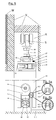
- the retaining rail 20 (see first Fig. 1 ) preferably has a uniform cross-sectional profile over its entire length and is preferably cut to length from an aluminum extruded profile. In places, however, the cross-sectional profile deviates due to Recesses or holes 214, 23 from the uniform cross-sectional profile.
- the retaining rail 20 has different cross-sectional profiles over the length, in particular at the ends of the retaining rail.
- the cross-sectional profile of the retaining rail 20 has an area on the C-shaped. This region forms a first receptacle 21 for receiving the seal 30.
- a second region of the cross-sectional profile is approximately U-shaped and forms a second receptacle and a fastening structure for fastening the retaining rail 20 to the carriage S.
- the first shot and the second shot may also be described as a groove.
- the groove of the first receptacle then has groove walls 211, 212 which are connected by a web 213.
- the groove of the second receptacle has groove walls 221, 222 which are connected by a web which at the same time forms a groove wall 211 of the two groove walls 211, 212 of the first receptacle.
- the groove walls 211, 212 of the first receptacle are free of undercuts, which facilitates insertion of the seal 30 into the first receptacle.
- At least one threaded bore 214 is preferably provided in the vicinity of the web 213.
- a threaded pin 40 may be screwed.
- a tip of the grub screw presses into a housing 32 of the seal and thus fixes the seal in the first receptacle.
- the threaded pin 40 preferably has a hexagon socket key surface, which allows easy handling even with a hanging on the running rail R sliding door.
- a plurality of pairs of aligned round holes 23, 24 are provided in both groove walls 211, 212 of the first receptacle.
- Each round hole 23 is provided in the groove wall 211 and has a diameter which is so large that a screw 130 including its head can be passed through the round hole 23.
- the round holes 24 in the groove wall 212 have a smaller diameter, which is dimensioned so that, although a shaft of a screw 130 can be passed, but not the head.
- the screw 130 is a countersunk screw.
- the edge of the round hole 24 in the groove wall 212 is lowered, so that the head of the screw 130 can be completely received in the round hole 24.
- the screw 130 serves to attach the retaining rail 20 to the door leaf 10.
- the screw 130 is passed through the second receptacle 22 and through the circular holes 23 and inserted into the round holes 24, and is then screwed into the door leaf 10.
- the groove of the second receptacle is designed so that the screw 130 can be passed between the groove walls 221, 222 of the second receptacle.
- the smallest distance between the groove walls 221, 222 is therefore greater than the diameter of the head of the screw 130th
- the groove walls 221, 222 of the second receptacle 22 have edges that cant inwardly, whereby the groove walls 221, 222 are undercut.
- the undercut edges of the groove walls 221, 222 can be engaged behind by heads 52 of screws 50.
- Shanks 51 of these screws 50 pass through the gap between the edges of the groove walls and protrude outward from the second receptacle 22. With nuts 70 placed on the shanks 51, the screws 50 can be fixed in the second receptacle 22. The ends the screws 50 can be screwed into the carriages S and secured there with additional nuts 80 placed on the screws 50.
- the voltage applied to the door leaf 10 outside of the groove wall 212 has a groove along the retaining rail 20.
- a seal 120 may be used, which may seal between the support rail 20 and the door panel 10 resulting column.
- washers 60 may be provided between the nuts 70 and the screw heads 52 on the one hand and the retaining rail 20 on the other hand washers 60 may be provided. Also on the nuts 80 Unterlegetern 60 may be provided.
- the carriage S of the sliding door are preferably arranged displaceably in rails R.
- the height and / or orientation of the door leaf can be adjusted by a skillful use of the nuts 70, 80 (see FIG Fig. 3a to 3c ).
- This method for adjusting the height and / or orientation can also be used for sliding without a support rail, in which the screws 50 are either freely rotatable, indirectly or directly on the door leaf or in threaded bushes directly or indirectly attached to the door leaf.
- the lower, applied to the support rail 20 nut 70 is released.
- the upper, applied to the carriage nut 80 is released. Both nuts 70, 80 are rotated against each other and countered.
- the countered nuts 70, 80 can be rotated simultaneously without the one or the other nut 70, 80 can be rotated on the screw 50. Ie. the moments introduced into the nuts 70, 80 lead to a rotation of the screw 50. This makes it possible for the Continue screwing screw 50 into carriage S or detaching it from carriage S.
- FIGS. 4 and 5 shown sliding door is mounted on the carriage S and the track rail R on a panel V, which is fixed to a wall W.
- a seal 20 inserted in the first receptacle 21 of the retaining rail 20 is in an untripped state. This means that a sealing profile 31 fastened to a retaining profile 33 lies largely within the first receptacle.
- the sliding door also has an automatically releasable sliding bottom seal 90.
- This is arranged in a groove in a lower end face of the door leaf, as for example from the document EP 1 860 272 A2 is known.
- the bottom seal may in principle be designed in the same way as the seal in the first receptacle 21.
- the bottom seal also has a housing 92, a trigger (not shown), a mechanism (not shown) for transmitting the movement of the trigger, a retaining rail 95 , which is driven by the mechanism, and a sealing profile 91, which is fixed to the support rail 95.
- the bottom seal can be attached to the door leaf 10 via retaining brackets 93, which are inserted into the housing 92 at the end, and screws 94.
- the groove in the lower end side of the door leaf 10 is milled out wider than would be necessary for receiving the bottom seal 90. Since the housing 92 of the bottom seal 90 abuts on one side on a wall of the groove in the lower end face, a gap remains on the opposite side between the housing 92 and the other wall of the groove. This gap serves to receive a guide element 11, which is fastened to the floor F and has a wing projecting into the gap. By the guide member 11 of the door 10 is guided at its lower end when moving.
- a seal 100 is provided in a groove bottom of the groove provided in the lower end face of the door leaf 10.
- This seal 100 which preferably consists of an elastic sealing profile seals against a draft or a sound transmission through the gap between groove wall and seal housing 92 and groove bottom and seal housing 92.
- the seal 100 has elastic retaining elements 101, which deform when inserting the seal 100 in the gap and hold the seal frictionally in the gap.
- the holding elements 101 are preferably in a longitudinal direction of the seal 100 extending lamellae or wings.
- the in the Figures 6a to 8c shown sliding doors have a door leaf 10 which hangs on a support rail 20.
- the retaining rail 20 is connected by screws, which are screwed into the upper end face of the door leaf 10, with the door leaf 10.
- screws 50 are mounted, which connect the support rail 20 with carriage S, which are guided in a guide rail R slidably.
- the door leaf 10 can be aligned by means of the screws 50 and by means of nuts 70, 80 placed on the screws.
- the door leaf 10 depends approximately perpendicularly viewed from the side.
- a wall W with a door opening that can be closed by the door leaf is often not perpendicular to what is in Fig. 6d something is exaggerated. Due to the almost perpendicular hanging of the door panel 10 and the perpendicular deviating wall, a gap between the door panel 10 and the wall W is wider at one end than at the other end. This presents problems in sealing the gap in the closed state of the door with a seal 150 attached to the door panel 10 or the wall.
- the compensation means 160 are suitable and arranged to compensate for the deviation of the wall W from the perpendicular.
- the compensating means 160 is in the in the FIGS. 6a to 6d shown sliding door has two parts and has a rectangular cross-section bar 163, which extends at least over the entire height of the door leaf 10, but advantageously extends from the floor F to the door panel 10.
- the strip 163 has a longitudinal slot which extends over the entire bar 163. Transverse to the slot 163 threaded holes are provided in the bar.
- the compensating means has as a second part an angle bar 162 on which the bar 163 is attached.
- a first leg of the angle bar 163 is attached to the wall by screws 190.
- On a second leg the bar 163 is attached.
- the strip 163 is attached to the longitudinal slot on the second leg of the angle bar 162.
- slots 161 are provided which are provided at right angles to the main extension direction of the angle bar 162.
- the distance of the slots 161 corresponds to the distance of the threaded holes in the bar 163.
- Screws 180 are screwed into the threaded holes of the bar 163 and pass through the slots 161 in the angle bar 162.
- the bar 163 and the angle bar 162 are secured by these screws 180 together. If the screws 180 are somewhat loosened, the bar 163 can be rotated relative to the angle bar 162, whereby a vertical alignment of the compensating means 160 is possible.
- the seal 150 is mounted, which seals the gap between the wall W and the door leaf. Due to the vertical alignment of the compensating means 160, the gap between the door leaf 10 and the wall is the same width at all points, so that a problem-free sealing is possible.
- the compensating means 160 While in the example of FIGS. 6a to 6c the compensating means 160 is attached by means of the angle strip 162 on an outer side of the wall W, the compensating means in the example of FIGS. 7a to 7d mounted in the soffit of the door opening in the wall W.
- the attachment of the compensating means takes place directly on the wall W by means of screws 180, which are passed through transversely to the main extension direction provided slots 161 in the compensating means 160.
- By means of the elongated holes 161 it is possible to fasten the compensation means 180 aligned perpendicular to the wall W.
- the compensating means 160 is formed by an angle strip, for example, a rectangular bent sheet metal.
- the compensating means 160 extends over the height of the door leaf 10. It is attached to a lateral end face of the door leaf 10.
- 160 elongated holes 161 are provided in a first leg of the compensating means, which extend transversely to the main extension direction.
- the compensating means is screwed to the door leaf 10.
- the attached to the door leaf 10 legs of the compensating means 160 is covered by a cover 200, which also covers the slots 161 visually appealing.
Landscapes
- Engineering & Computer Science (AREA)
- Civil Engineering (AREA)
- Structural Engineering (AREA)
- Mechanical Engineering (AREA)
- Specific Sealing Or Ventilating Devices For Doors And Windows (AREA)
- Support Devices For Sliding Doors (AREA)
Priority Applications (1)
| Application Number | Priority Date | Filing Date | Title |
|---|---|---|---|
| EP15156621.3A EP2927409B1 (fr) | 2010-03-17 | 2011-03-15 | Joint pour une porte coulissante |
Applications Claiming Priority (1)
| Application Number | Priority Date | Filing Date | Title |
|---|---|---|---|
| DE102010011770A DE102010011770A1 (de) | 2010-03-17 | 2010-03-17 | Halteschiene, Ausgleichsmittel und Dichtung für eine Schiebetür sowie Schiebetür mit der Halteschiene, dem Ausgleichsmittel und/oder der Dichtung |
Related Child Applications (2)
| Application Number | Title | Priority Date | Filing Date |
|---|---|---|---|
| EP15156621.3A Division EP2927409B1 (fr) | 2010-03-17 | 2011-03-15 | Joint pour une porte coulissante |
| EP15156621.3A Division-Into EP2927409B1 (fr) | 2010-03-17 | 2011-03-15 | Joint pour une porte coulissante |
Publications (3)
| Publication Number | Publication Date |
|---|---|
| EP2366857A2 true EP2366857A2 (fr) | 2011-09-21 |
| EP2366857A3 EP2366857A3 (fr) | 2014-06-04 |
| EP2366857B1 EP2366857B1 (fr) | 2017-06-14 |
Family
ID=44278748
Family Applications (2)
| Application Number | Title | Priority Date | Filing Date |
|---|---|---|---|
| EP15156621.3A Active EP2927409B1 (fr) | 2010-03-17 | 2011-03-15 | Joint pour une porte coulissante |
| EP11158313.4A Active EP2366857B1 (fr) | 2010-03-17 | 2011-03-15 | Agencement de fixation pour une porte coulissante |
Family Applications Before (1)
| Application Number | Title | Priority Date | Filing Date |
|---|---|---|---|
| EP15156621.3A Active EP2927409B1 (fr) | 2010-03-17 | 2011-03-15 | Joint pour une porte coulissante |
Country Status (3)
| Country | Link |
|---|---|
| EP (2) | EP2927409B1 (fr) |
| DE (1) | DE102010011770A1 (fr) |
| DK (1) | DK2366857T3 (fr) |
Cited By (2)
| Publication number | Priority date | Publication date | Assignee | Title |
|---|---|---|---|---|
| WO2019147726A3 (fr) * | 2018-01-23 | 2019-09-06 | Dirtt Environmental Solutions Inc. | Porte à joints acoustiques |
| EP3825503A1 (fr) | 2019-11-25 | 2021-05-26 | ASSA ABLOY (Schweiz) AG | Dispositif d'étanchéité d'une porte coulissante |
Families Citing this family (4)
| Publication number | Priority date | Publication date | Assignee | Title |
|---|---|---|---|---|
| DE102011122036A1 (de) | 2011-12-22 | 2013-06-27 | Agtatec Ag | Aktive Dichtungsvorrichtung und Schiebetür mit aktiver Dichtungsvorrichtung |
| DE202014102418U1 (de) | 2014-05-23 | 2015-08-28 | Hücking GmbH | Profilschienensystem für den Einbau von Schiebetüren in Hohlwände |
| DE102016121520A1 (de) * | 2016-11-10 | 2018-05-17 | Athmer Ohg | Fingerschutzvorrichtung an einer Schiebetür |
| DE102017121792A1 (de) | 2017-09-20 | 2019-03-21 | Athmer Ohg | Spaltabdichtung |
Citations (1)
| Publication number | Priority date | Publication date | Assignee | Title |
|---|---|---|---|---|
| EP1860272A2 (fr) | 2006-05-22 | 2007-11-28 | Firma F. Athmer | Joints, en particulier pour une porte coulissante et dispositif de joint |
Family Cites Families (16)
| Publication number | Priority date | Publication date | Assignee | Title |
|---|---|---|---|---|
| US3309816A (en) * | 1964-05-28 | 1967-03-21 | Jr Benjamin D Malone | Movable partition structures |
| US3672424A (en) * | 1971-03-03 | 1972-06-27 | Ram Partitions Ltd | Movable partition wall |
| DE2157832C3 (de) * | 1971-11-22 | 1974-08-01 | Werner Frach | Fenster, Tür oder dergleichen mit einem oder mehreren Flügeln und mit einer Dichtung |
| US3755968A (en) * | 1972-01-20 | 1973-09-04 | Hough Mfg Corp | Floating constant contact seal for operable partitions |
| DE8627911U1 (de) * | 1986-10-20 | 1986-12-11 | Nivomed-Medizintechnik GmbH, 5110 Alsdorf | Laufwerkskasten für Schiebetüren, insbesondere von Operationsräumen |
| DE4106116A1 (de) * | 1991-02-27 | 1992-09-03 | Semer Gmbh & Co Kg W | Rahmen fuer trennwaende, insbesondere fuer duschabtrennungen u. dgl. |
| DE9111947U1 (de) * | 1991-09-25 | 1991-12-12 | Spier GmbH, 4939 Steinheim | Schiebetür- oder -fenster mit Führungsprofilleiste |
| JP3328525B2 (ja) * | 1996-11-19 | 2002-09-24 | 日本板硝子環境アメニティ株式会社 | 電磁波シールドドア構造 |
| DE19718238C2 (de) * | 1997-04-30 | 2000-03-23 | Theo Schroeders | Als Schiebetür oder -tor ausgebildeter Rauchschutzabschluß |
| GB2327102A (en) * | 1997-07-09 | 1999-01-13 | Red | A one-piece replacement parting bead carrying sealing means for mounting on a sash window |
| DE10160802A1 (de) * | 2001-12-11 | 2003-06-18 | Geze Gmbh | Automatische Schiebetüranlage mit Seitenprofil |
| DE10259924B4 (de) * | 2002-12-20 | 2008-04-30 | Geze Gmbh | Schiebetüranlage |
| US20060064937A1 (en) * | 2004-09-29 | 2006-03-30 | Danczek James A | Weather strip assembly and method of application of same |
| DE202007006127U1 (de) * | 2007-04-28 | 2008-09-11 | SCHÜCO International KG | Schiebeelement |
| DE102007028465A1 (de) * | 2007-06-18 | 2008-12-24 | Inge Frey | Dichtkissen |
| DE202009006059U1 (de) * | 2009-04-27 | 2009-09-17 | Joh. Sprinz Gmbh & Co. Kg | Schiebetürbeschlag |
-
2010
- 2010-03-17 DE DE102010011770A patent/DE102010011770A1/de not_active Ceased
-
2011
- 2011-03-15 EP EP15156621.3A patent/EP2927409B1/fr active Active
- 2011-03-15 DK DK11158313.4T patent/DK2366857T3/en active
- 2011-03-15 EP EP11158313.4A patent/EP2366857B1/fr active Active
Patent Citations (1)
| Publication number | Priority date | Publication date | Assignee | Title |
|---|---|---|---|---|
| EP1860272A2 (fr) | 2006-05-22 | 2007-11-28 | Firma F. Athmer | Joints, en particulier pour une porte coulissante et dispositif de joint |
Cited By (3)
| Publication number | Priority date | Publication date | Assignee | Title |
|---|---|---|---|---|
| WO2019147726A3 (fr) * | 2018-01-23 | 2019-09-06 | Dirtt Environmental Solutions Inc. | Porte à joints acoustiques |
| US11326393B2 (en) | 2018-01-23 | 2022-05-10 | Dirtt Environmental Solutions Ltd. | Door with acoustic seals |
| EP3825503A1 (fr) | 2019-11-25 | 2021-05-26 | ASSA ABLOY (Schweiz) AG | Dispositif d'étanchéité d'une porte coulissante |
Also Published As
| Publication number | Publication date |
|---|---|
| EP2927409A1 (fr) | 2015-10-07 |
| EP2366857B1 (fr) | 2017-06-14 |
| EP2927409B1 (fr) | 2017-05-10 |
| DK2366857T3 (en) | 2017-09-18 |
| DE102010011770A1 (de) | 2011-09-22 |
| EP2366857A3 (fr) | 2014-06-04 |
Similar Documents
| Publication | Publication Date | Title |
|---|---|---|
| EP2927409B1 (fr) | Joint pour une porte coulissante | |
| EP2233676A2 (fr) | Connecteur de rembourrage | |
| AT511046B1 (de) | Rahmensystem eines partikelschutzgitters | |
| EP3235983A1 (fr) | Installation de porte coulissante et systeme a rails | |
| EP2213825B1 (fr) | Barre de dormant d'un dormant de portes ou de portails dotés d'un dispositif de fixation | |
| EP1659246A1 (fr) | Charnière pour volets | |
| DE202005010512U1 (de) | Halterung zur Einspannung einer Glasscheibe | |
| EP3118404B1 (fr) | Charniere, notamment pour portes en matiere synthetique et fenetre en matiere synthetique | |
| EP2365166A2 (fr) | Bande de porte, notamment pour portes de fermeture de bâtiment | |
| EP1439269B1 (fr) | Etrier d'ancrage pour profilés pour installations sanitaires et chassis avec un tel étrier | |
| DE102004005422A1 (de) | Montagekonsole für Fenster oder dergleichen | |
| EP2080862A2 (fr) | Ferrure de serrage | |
| EP2744960B1 (fr) | Partie de support de fenêtre, de porte ou analogues | |
| DE202007011076U1 (de) | Bandanordnung mit Führungsprofil | |
| EP2400091B1 (fr) | Penture de porte pour le montage sur des systèmes de chambres creuses | |
| DE102010004772B3 (de) | Türband für Aluminiumtüren | |
| EP1653030B1 (fr) | Charnière avec au moins deux éléments de charnière destinés à être assemblés avec un élément de support et de réception | |
| DE102008006800B4 (de) | Führungsvorrichtung für einen Schiebeflügel | |
| EP2169167A1 (fr) | Dispositif de réglage de la distance entre deux chariots se déplaçant sur un rail commun et procédé | |
| EP2108774B1 (fr) | Charnière | |
| EP1619333A2 (fr) | Charnière pour portes, fenêtres et similaires | |
| DE102007025857A1 (de) | Gelenkband für Türen oder Fenster | |
| EP2420643A1 (fr) | Dispositif de fixation orientable d'un store de fenêtre ou analogue | |
| DE202006010209U1 (de) | Band für Türen, Fenster o.dgl. | |
| DE102011008765A1 (de) | Profilanordnung, Rahmen und Rahmenanordnung |
Legal Events
| Date | Code | Title | Description |
|---|---|---|---|
| PUAI | Public reference made under article 153(3) epc to a published international application that has entered the european phase |
Free format text: ORIGINAL CODE: 0009012 |
|
| AK | Designated contracting states |
Kind code of ref document: A2 Designated state(s): AL AT BE BG CH CY CZ DE DK EE ES FI FR GB GR HR HU IE IS IT LI LT LU LV MC MK MT NL NO PL PT RO RS SE SI SK SM TR |
|
| AX | Request for extension of the european patent |
Extension state: BA ME |
|
| RIC1 | Information provided on ipc code assigned before grant |
Ipc: E06B 3/46 20060101ALI20140226BHEP Ipc: E05D 15/06 20060101AFI20140226BHEP Ipc: E06B 7/16 20060101ALI20140226BHEP |
|
| PUAL | Search report despatched |
Free format text: ORIGINAL CODE: 0009013 |
|
| AK | Designated contracting states |
Kind code of ref document: A3 Designated state(s): AL AT BE BG CH CY CZ DE DK EE ES FI FR GB GR HR HU IE IS IT LI LT LU LV MC MK MT NL NO PL PT RO RS SE SI SK SM TR |
|
| AX | Request for extension of the european patent |
Extension state: BA ME |
|
| RIC1 | Information provided on ipc code assigned before grant |
Ipc: E06B 3/46 20060101ALI20140430BHEP Ipc: E06B 7/16 20060101ALI20140430BHEP Ipc: E05D 15/06 20060101AFI20140430BHEP |
|
| 17P | Request for examination filed |
Effective date: 20141204 |
|
| RAX | Requested extension states of the european patent have changed |
Extension state: ME Payment date: 20141204 Extension state: BA Payment date: 20141204 |
|
| RBV | Designated contracting states (corrected) |
Designated state(s): AL AT BE BG CH CY CZ DE DK EE ES FI FR GB GR HR HU IE IS IT LI LT LU LV MC MK MT NL NO PL PT RO RS SE SI SK SM TR |
|
| GRAP | Despatch of communication of intention to grant a patent |
Free format text: ORIGINAL CODE: EPIDOSNIGR1 |
|
| RIC1 | Information provided on ipc code assigned before grant |
Ipc: E06B 7/16 20060101ALI20160517BHEP Ipc: E05D 15/06 20060101AFI20160517BHEP Ipc: E06B 3/46 20060101ALI20160517BHEP Ipc: E06B 7/21 20060101ALI20160517BHEP |
|
| GRAJ | Information related to disapproval of communication of intention to grant by the applicant or resumption of examination proceedings by the epo deleted |
Free format text: ORIGINAL CODE: EPIDOSDIGR1 |
|
| INTG | Intention to grant announced |
Effective date: 20160623 |
|
| GRAP | Despatch of communication of intention to grant a patent |
Free format text: ORIGINAL CODE: EPIDOSNIGR1 |
|
| INTG | Intention to grant announced |
Effective date: 20160727 |
|
| GRAJ | Information related to disapproval of communication of intention to grant by the applicant or resumption of examination proceedings by the epo deleted |
Free format text: ORIGINAL CODE: EPIDOSDIGR1 |
|
| GRAP | Despatch of communication of intention to grant a patent |
Free format text: ORIGINAL CODE: EPIDOSNIGR1 |
|
| INTC | Intention to grant announced (deleted) | ||
| INTG | Intention to grant announced |
Effective date: 20170102 |
|
| GRAS | Grant fee paid |
Free format text: ORIGINAL CODE: EPIDOSNIGR3 |
|
| GRAA | (expected) grant |
Free format text: ORIGINAL CODE: 0009210 |
|
| AK | Designated contracting states |
Kind code of ref document: B1 Designated state(s): AL AT BE BG CH CY CZ DE DK EE ES FI FR GB GR HR HU IE IS IT LI LT LU LV MC MK MT NL NO PL PT RO RS SE SI SK SM TR |
|
| REG | Reference to a national code |
Ref country code: GB Ref legal event code: FG4D Free format text: NOT ENGLISH |
|
| REG | Reference to a national code |
Ref country code: CH Ref legal event code: EP Ref country code: AT Ref legal event code: REF Ref document number: 901124 Country of ref document: AT Kind code of ref document: T Effective date: 20170615 |
|
| REG | Reference to a national code |
Ref country code: IE Ref legal event code: FG4D Free format text: LANGUAGE OF EP DOCUMENT: GERMAN |
|
| REG | Reference to a national code |
Ref country code: DE Ref legal event code: R096 Ref document number: 502011012425 Country of ref document: DE |
|
| REG | Reference to a national code |
Ref country code: NL Ref legal event code: FP |
|
| REG | Reference to a national code |
Ref country code: DK Ref legal event code: T3 Effective date: 20170914 |
|
| REG | Reference to a national code |
Ref country code: SE Ref legal event code: TRGR |
|
| REG | Reference to a national code |
Ref country code: LT Ref legal event code: MG4D |
|
| PG25 | Lapsed in a contracting state [announced via postgrant information from national office to epo] |
Ref country code: HR Free format text: LAPSE BECAUSE OF FAILURE TO SUBMIT A TRANSLATION OF THE DESCRIPTION OR TO PAY THE FEE WITHIN THE PRESCRIBED TIME-LIMIT Effective date: 20170614 Ref country code: ES Free format text: LAPSE BECAUSE OF FAILURE TO SUBMIT A TRANSLATION OF THE DESCRIPTION OR TO PAY THE FEE WITHIN THE PRESCRIBED TIME-LIMIT Effective date: 20170614 Ref country code: LT Free format text: LAPSE BECAUSE OF FAILURE TO SUBMIT A TRANSLATION OF THE DESCRIPTION OR TO PAY THE FEE WITHIN THE PRESCRIBED TIME-LIMIT Effective date: 20170614 Ref country code: NO Free format text: LAPSE BECAUSE OF FAILURE TO SUBMIT A TRANSLATION OF THE DESCRIPTION OR TO PAY THE FEE WITHIN THE PRESCRIBED TIME-LIMIT Effective date: 20170914 Ref country code: FI Free format text: LAPSE BECAUSE OF FAILURE TO SUBMIT A TRANSLATION OF THE DESCRIPTION OR TO PAY THE FEE WITHIN THE PRESCRIBED TIME-LIMIT Effective date: 20170614 Ref country code: GR Free format text: LAPSE BECAUSE OF FAILURE TO SUBMIT A TRANSLATION OF THE DESCRIPTION OR TO PAY THE FEE WITHIN THE PRESCRIBED TIME-LIMIT Effective date: 20170915 |
|
| PG25 | Lapsed in a contracting state [announced via postgrant information from national office to epo] |
Ref country code: RS Free format text: LAPSE BECAUSE OF FAILURE TO SUBMIT A TRANSLATION OF THE DESCRIPTION OR TO PAY THE FEE WITHIN THE PRESCRIBED TIME-LIMIT Effective date: 20170614 Ref country code: LV Free format text: LAPSE BECAUSE OF FAILURE TO SUBMIT A TRANSLATION OF THE DESCRIPTION OR TO PAY THE FEE WITHIN THE PRESCRIBED TIME-LIMIT Effective date: 20170614 Ref country code: BG Free format text: LAPSE BECAUSE OF FAILURE TO SUBMIT A TRANSLATION OF THE DESCRIPTION OR TO PAY THE FEE WITHIN THE PRESCRIBED TIME-LIMIT Effective date: 20170914 |
|
| PG25 | Lapsed in a contracting state [announced via postgrant information from national office to epo] |
Ref country code: EE Free format text: LAPSE BECAUSE OF FAILURE TO SUBMIT A TRANSLATION OF THE DESCRIPTION OR TO PAY THE FEE WITHIN THE PRESCRIBED TIME-LIMIT Effective date: 20170614 Ref country code: CZ Free format text: LAPSE BECAUSE OF FAILURE TO SUBMIT A TRANSLATION OF THE DESCRIPTION OR TO PAY THE FEE WITHIN THE PRESCRIBED TIME-LIMIT Effective date: 20170614 Ref country code: SK Free format text: LAPSE BECAUSE OF FAILURE TO SUBMIT A TRANSLATION OF THE DESCRIPTION OR TO PAY THE FEE WITHIN THE PRESCRIBED TIME-LIMIT Effective date: 20170614 Ref country code: RO Free format text: LAPSE BECAUSE OF FAILURE TO SUBMIT A TRANSLATION OF THE DESCRIPTION OR TO PAY THE FEE WITHIN THE PRESCRIBED TIME-LIMIT Effective date: 20170614 |
|
| PG25 | Lapsed in a contracting state [announced via postgrant information from national office to epo] |
Ref country code: IS Free format text: LAPSE BECAUSE OF FAILURE TO SUBMIT A TRANSLATION OF THE DESCRIPTION OR TO PAY THE FEE WITHIN THE PRESCRIBED TIME-LIMIT Effective date: 20171014 Ref country code: SM Free format text: LAPSE BECAUSE OF FAILURE TO SUBMIT A TRANSLATION OF THE DESCRIPTION OR TO PAY THE FEE WITHIN THE PRESCRIBED TIME-LIMIT Effective date: 20170614 Ref country code: PL Free format text: LAPSE BECAUSE OF FAILURE TO SUBMIT A TRANSLATION OF THE DESCRIPTION OR TO PAY THE FEE WITHIN THE PRESCRIBED TIME-LIMIT Effective date: 20170614 Ref country code: IT Free format text: LAPSE BECAUSE OF FAILURE TO SUBMIT A TRANSLATION OF THE DESCRIPTION OR TO PAY THE FEE WITHIN THE PRESCRIBED TIME-LIMIT Effective date: 20170614 |
|
| REG | Reference to a national code |
Ref country code: DE Ref legal event code: R097 Ref document number: 502011012425 Country of ref document: DE |
|
| PLBE | No opposition filed within time limit |
Free format text: ORIGINAL CODE: 0009261 |
|
| STAA | Information on the status of an ep patent application or granted ep patent |
Free format text: STATUS: NO OPPOSITION FILED WITHIN TIME LIMIT |
|
| 26N | No opposition filed |
Effective date: 20180315 |
|
| PG25 | Lapsed in a contracting state [announced via postgrant information from national office to epo] |
Ref country code: SI Free format text: LAPSE BECAUSE OF FAILURE TO SUBMIT A TRANSLATION OF THE DESCRIPTION OR TO PAY THE FEE WITHIN THE PRESCRIBED TIME-LIMIT Effective date: 20170614 |
|
| PG25 | Lapsed in a contracting state [announced via postgrant information from national office to epo] |
Ref country code: MT Free format text: LAPSE BECAUSE OF FAILURE TO SUBMIT A TRANSLATION OF THE DESCRIPTION OR TO PAY THE FEE WITHIN THE PRESCRIBED TIME-LIMIT Effective date: 20170614 |
|
| PG25 | Lapsed in a contracting state [announced via postgrant information from national office to epo] |
Ref country code: MC Free format text: LAPSE BECAUSE OF FAILURE TO SUBMIT A TRANSLATION OF THE DESCRIPTION OR TO PAY THE FEE WITHIN THE PRESCRIBED TIME-LIMIT Effective date: 20170614 |
|
| REG | Reference to a national code |
Ref country code: BE Ref legal event code: MM Effective date: 20180331 |
|
| REG | Reference to a national code |
Ref country code: IE Ref legal event code: MM4A |
|
| PG25 | Lapsed in a contracting state [announced via postgrant information from national office to epo] |
Ref country code: LU Free format text: LAPSE BECAUSE OF NON-PAYMENT OF DUE FEES Effective date: 20180315 |
|
| PG25 | Lapsed in a contracting state [announced via postgrant information from national office to epo] |
Ref country code: IE Free format text: LAPSE BECAUSE OF NON-PAYMENT OF DUE FEES Effective date: 20180315 |
|
| PG25 | Lapsed in a contracting state [announced via postgrant information from national office to epo] |
Ref country code: BE Free format text: LAPSE BECAUSE OF NON-PAYMENT OF DUE FEES Effective date: 20180331 |
|
| PG25 | Lapsed in a contracting state [announced via postgrant information from national office to epo] |
Ref country code: FR Free format text: LAPSE BECAUSE OF NON-PAYMENT OF DUE FEES Effective date: 20180331 |
|
| PG25 | Lapsed in a contracting state [announced via postgrant information from national office to epo] |
Ref country code: TR Free format text: LAPSE BECAUSE OF FAILURE TO SUBMIT A TRANSLATION OF THE DESCRIPTION OR TO PAY THE FEE WITHIN THE PRESCRIBED TIME-LIMIT Effective date: 20170614 |
|
| PG25 | Lapsed in a contracting state [announced via postgrant information from national office to epo] |
Ref country code: HU Free format text: LAPSE BECAUSE OF FAILURE TO SUBMIT A TRANSLATION OF THE DESCRIPTION OR TO PAY THE FEE WITHIN THE PRESCRIBED TIME-LIMIT; INVALID AB INITIO Effective date: 20110315 Ref country code: PT Free format text: LAPSE BECAUSE OF FAILURE TO SUBMIT A TRANSLATION OF THE DESCRIPTION OR TO PAY THE FEE WITHIN THE PRESCRIBED TIME-LIMIT Effective date: 20170614 |
|
| PG25 | Lapsed in a contracting state [announced via postgrant information from national office to epo] |
Ref country code: MK Free format text: LAPSE BECAUSE OF NON-PAYMENT OF DUE FEES Effective date: 20170614 Ref country code: CY Free format text: LAPSE BECAUSE OF FAILURE TO SUBMIT A TRANSLATION OF THE DESCRIPTION OR TO PAY THE FEE WITHIN THE PRESCRIBED TIME-LIMIT Effective date: 20170614 |
|
| PG25 | Lapsed in a contracting state [announced via postgrant information from national office to epo] |
Ref country code: AL Free format text: LAPSE BECAUSE OF FAILURE TO SUBMIT A TRANSLATION OF THE DESCRIPTION OR TO PAY THE FEE WITHIN THE PRESCRIBED TIME-LIMIT Effective date: 20170614 |
|
| P01 | Opt-out of the competence of the unified patent court (upc) registered |
Effective date: 20230616 |
|
| PGFP | Annual fee paid to national office [announced via postgrant information from national office to epo] |
Ref country code: NL Payment date: 20240320 Year of fee payment: 14 |
|
| PGFP | Annual fee paid to national office [announced via postgrant information from national office to epo] |
Ref country code: AT Payment date: 20240321 Year of fee payment: 14 |
|
| PGFP | Annual fee paid to national office [announced via postgrant information from national office to epo] |
Ref country code: DE Payment date: 20240331 Year of fee payment: 14 Ref country code: GB Payment date: 20240320 Year of fee payment: 14 |
|
| PGFP | Annual fee paid to national office [announced via postgrant information from national office to epo] |
Ref country code: SE Payment date: 20240320 Year of fee payment: 14 Ref country code: DK Payment date: 20240326 Year of fee payment: 14 |
|
| PGFP | Annual fee paid to national office [announced via postgrant information from national office to epo] |
Ref country code: CH Payment date: 20240401 Year of fee payment: 14 |