EP2364862B1 - Stift, insbesondere Schreibstift - Google Patents
Stift, insbesondere Schreibstift Download PDFInfo
- Publication number
- EP2364862B1 EP2364862B1 EP20100156267 EP10156267A EP2364862B1 EP 2364862 B1 EP2364862 B1 EP 2364862B1 EP 20100156267 EP20100156267 EP 20100156267 EP 10156267 A EP10156267 A EP 10156267A EP 2364862 B1 EP2364862 B1 EP 2364862B1
- Authority
- EP
- European Patent Office
- Prior art keywords
- shaft
- inner part
- stylus
- stylus according
- locking
- Prior art date
- Legal status (The legal status is an assumption and is not a legal conclusion. Google has not performed a legal analysis and makes no representation as to the accuracy of the status listed.)
- Not-in-force
Links
Images


Classifications
-
- B—PERFORMING OPERATIONS; TRANSPORTING
- B43—WRITING OR DRAWING IMPLEMENTS; BUREAU ACCESSORIES
- B43K—IMPLEMENTS FOR WRITING OR DRAWING
- B43K7/00—Ball-point pens
- B43K7/12—Ball-point pens with retractable ball points
-
- B—PERFORMING OPERATIONS; TRANSPORTING
- B43—WRITING OR DRAWING IMPLEMENTS; BUREAU ACCESSORIES
- B43K—IMPLEMENTS FOR WRITING OR DRAWING
- B43K24/00—Mechanisms for selecting, projecting, retracting or locking writing units
- B43K24/02—Mechanisms for selecting, projecting, retracting or locking writing units for locking a single writing unit in only fully projected or retracted positions
Definitions
- the invention relates to a pen, in particular a pen.
- Conventional pins usually comprise a rod-shaped shaft, the front end of which tapers to a point or carries such a tip, from which centrally a lead, so as a lead, a ballpoint pen refills o. The like. Protrudes.
- a pen is held by the users usually at the front end with thumb, index and middle finger.
- a variation of the distance of the pin or its lead to a writing pad requires a changed attitude of the hand with unchanged grip position at the front end of the shaft. This may be difficult for some people for some anatomical reasons. For students learning to write, a relaxed hand position is crucial for a good typeface and overall learning. An unfavorable hand and finger anatomy compared to the size of the pen or health restrictions may prevent this goal.
- a pin according to claim 1 This comprises a sleeve-shaped shaft and arranged within the shaft, with its front end protruding from the shaft with a projection and a mine-bearing inner part, wherein the shaft and inner part are axially adjustably connected to each other.
- This embodiment makes it possible that the supernatant of the inner part can be increased or decreased as needed, so that the writing is easily possible with a relaxed for the user or to be taken about from health or anatomical conditions hand position.
- a display device is present on the pin.
- An easily manufactured variant of such a device is an axially extending marking on a longitudinal section of the inner part, which moves at least partially into the shaft when it is moved in or out.
- the size or the length of the visible part of the marking is correlated with the length of the projection of the inner part.
- the marking may be formed approximately from axially spaced elements such as lines or dots or an axially changing color gradient.
- the adjustment of the inner part can be done in many ways.
- the shaft carries an internal thread, which cooperates with an external thread of the inner part, so that a relative rotation of said parts causes a feed or retraction of the inner part.
- the inner part and the shaft are connected axially displaceable.
- a once selected adjustment position of the inner part is not changed during writing, for example, the movement coupling between the inner part and the shaft be made stiff, so that it withstands the usual writing pressure.
- a latching device is provided, with the inner part and shaft are axially fixed to each other in different relative positions. The advantage here is that the inner part and shaft can be easily connected to each other, so that an adjustment of the inner part with little effort is possible.
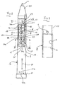
- An inventive pin comprises an inner part 1 and a sleeve-shaped shaft 2.
- the inner part 1 is designed substantially rod-shaped and is encompassed by the shaft 2.
- the inner part 1 protrudes from the front end of the shaft 2 with a projection 5.
- the supernatant 11 tapers to a tip 3, but may also have a different shape.
- a mine 4 is mounted, which protrudes from the top 3.
- the inner part 1 can in principle be designed arbitrarily, such as a mechanical pin, in which the mine via a feed mechanism (not shown) is movable.
- the mine 4 may also be mounted axially fixed in the inner part 1 and be about a ballpoint pen refill or the like. Of the Shaft 2 is held against the inner part 1 axially movable on this.
- the rear end of the inner part 1 is radially widened, whereby a pointing in the direction of the tip 3 radial shoulder 11 is formed.
- the shaft 2 has at its rear end a portion with an enlarged inner diameter, whereby also a radial shoulder 12 is formed.
- the two radial shoulders 11, 12 act together as abutment surfaces, whereby the rear axial position of the shaft 2 is predetermined.
- the shaft 2 is also, at least for a certain distance, mounted rotatably in the circumferential direction 13 on the inner part.
- a latching device which allows a relative displacement of inner part 1 and shaft 2 in predetermined latching positions.
- the latching device is designed in the manner of a Rastgesperres, wherein a configured in the form of a circular in plan view nub 6 latching element with recesses 7 on the inner part 1 cooperates.
- the latching recesses 7 are introduced into the outer circumferential surface 8 of the inner part 1.
- the nub 6 protrudes from the inner peripheral surface 9 of the shaft 2 and engages in each case in one of the recesses 7.
- the locking recesses 7 are arranged in an axial row, ie in the axial direction 10 one behind the other.
- the recesses 7 are each flanked in the axial direction 10 by 2 in the circumferential direction 13 extending webs 14.
- the upper side 15 of the webs 14 is aligned with the outer peripheral surface 8 of the inner part and has the same curvature as this.
- the recesses 7 are open and open into an existing in the outer peripheral surface 8, extending in the axial direction 10 longitudinal groove 16th
- Fig. 1 engages the knob 6 with a corresponding rotational position of the shaft 1 in the longitudinal groove 16 and can be moved axially.
- the knob 6 engages in a recess 7 a.
- the recesses 7 are each subdivided by a separating web 17 extending in the axial direction 10 into two parts 18, 19, the part 18 being in connection with the longitudinal groove 16.
- the dividers 17 extend in the radial direction 20 less far than the locking recesses 7 in the axial direction 10 flanking webs 14.
- the longitudinal groove 16 therefore has a depth 23 which is less than the depth 24 of the recesses 7.
- the wall portion 26 is integrally formed with its pointing in the circumferential direction 13a longitudinal edge 27 with the sleeve wall.
- the other longitudinal edge 28 and extending in the circumferential direction 13 transverse edges 29 and wall portion 26 are, however, cut free, ie between them and the sleeve wall 25 extends a Parting line 30a and 30b.
- a marking in the form of extending in the circumferential direction 13 and in the axial direction 10 in the grid of the recesses 7 spaced transverse bars 35 is provided on a longitudinal portion 34 at the rear end of the inner part 1.
- the longitudinal section 34 is more or less covered during the adjustment of the inner part 1 of the shaft 2 depending on the detent position.
- a total of seven locking recesses 7 and seven transverse lines 35 are present. In the in Fig. 1 shown situation, only two transverse lines 35 are visible.
Landscapes
- Mechanical Pencils And Projecting And Retracting Systems Therefor, And Multi-System Writing Instruments (AREA)
- Pens And Brushes (AREA)
Description
- Die Erfindung betrifft einen Stift, insbesondere einen Schreibstift. Herkömmliche Stifte umfassen üblicherweise einen stabförmigen Schaft, dessen Vorderende sich zu einer Spitze verjüngt oder der eine solche Spitze trägt, wobei aus diesem zentral eine Mine, also etwa eine Bleimine, eine Kugelschreibermine o. dgl. vorsteht. Ein Stift wird von den Benutzern in aller Regel am vorderen Ende mit Daumen, Zeige- und Mittelfinger gehalten. Eine Variierung des Abstandes des Stiftes bzw. seiner Mine zu einer Schreibunterlage erfordert bei unveränderter Griffposition am vordersten Schaftende eine veränderte Haltung der Hand. Dies kann für manche Personen etwa aus anatomischen Gründen schwierig sein. Bei Schülern, die das Schreiben erlernen, ist eine entspannte Haltung der Hand ausschlaggebend für ein gutes Schriftbild und den Lernerfolg insgesamt. Eine im Vergleich zur Stiftgröße ungünstige Hand-und Fingeranatomie oder etwa gesundheitliche Einschränkungen können diesem Ziel entgegenstehen.
- Davon ausgehend ist es die Aufgabe der Erfindung, einen Stift vorzuschlagen, der hier Abhilfe schafft.
- Diese Aufgabe wird mit einem Stift gemäß Anspruch 1 gelöst. Dieser umfasst einen hülsenförmigen Schaft und einen innerhalb des Schafts angeordneten, mit seinem vorderen Ende mit einem Überstand aus dem Schaft herausragenden und eine Mine tragenden Innenteil, wobei Schaft und Innenteil axial verstellbar miteinander verbunden sind. Diese Ausgestaltung ermöglicht es, dass der Überstand des Innenteils je nach Bedarf vergrößert oder verkleinert werden kann, so dass das Schreiben mit einer für den Benutzer entspannten oder einer etwa aus gesundheitlichen oder anatomischen Gegebenheiten einzunehmenden Handhaltung problemlos möglich ist.
- Um das Einstellen einer z.B. für eine bestimmte Schreibsituation günstige Verstellposition des Innenteils zu erleichtern, ist am Stift eine Anzeigevorrichtung vorhanden. Eine leicht herzustellende Variante einer solchen Einrichtung ist eine sich in Axialrichtung erstreckende Markierung an einem Längsabschnitt des Innenteils, der sich bei dessen Verstellung zumindest teilweise in den Schaft hinein bzw. heraus bewegt. Die Größe bzw. die Länge des sichtbaren Teils der Markierung ist dabei mit der Länge des Überstands des Innenteils korreliert. Die Markierung kann etwa von axial beabstandeten Elementen wie Strichen oder Punkten oder einem sich in Axialrichtung verändernden Farbverlauf gebildet sein.
- Die Verstellung des Innenteils kann auf vielfältige Art und Weise erfolgen. So ist es denkbar, dass der Schaft ein Innengewinde trägt, das mit einem Außengewinde des Innenteils zusammenwirkt, so dass eine Relativdrehung der genannten Teile einen Vorschub oder Rückschub des Innenteils bewirkt. Möglich ist aber auch, dass Innenteil und Schaft axial verschiebbar miteinander verbunden sind.
- Damit eine einmal gewählte Verstellposition des Innenteils während des Schreibens nicht verändert wird, kann beispielsweise die Bewegungskoppelung zwischen Innenteil und Schaft schwergängig ausgeführt sein, so dass sie dem üblichen Schreibdruck stand hält. Bei einer bevorzugten Ausgestaltung ist jedoch eine Rasteinrichtung vorgesehen, mit der Innenteil und Schaft in unterschiedlichen Relativpositionen axialfest aneinander fixierbar sind. Von Vorteil ist dabei, dass Innenteil und Schaft leichtgängig miteinander verbunden sein können, so dass eine Verstellung des Innenteils mit geringem Kraftaufwand möglich ist.
- Vorteilhafte Ausgestaltungen gehen aus der nun folgenden Beschreibung hervor, die auf die beigefügten Zeichnungen Bezug nimmt. Es zeigen:
- Fig. 1
- einen ein Innenteil und einen diesen umgreifenden Schaft aufweisenden Stift,
- Fig. 2
- das Innenteil in Seitenansicht,
- Fig. 3
- den Schaft in Längsschnittdarstellung,
- Fig. 4
- einen Schnitt des Schafts entsprechend der Linie IV-IV in
Fig. 2 , - Fig. 5
- einen Schnitt des Schafts entsprechend der Linie V-V in
Fig.2 . - Ein erfindungsgemäßer Stift umfasst ein Innenteil 1 sowie einen hülsenförmigen Schaft 2. Das Innenteil 1 ist im Wesentlichen stabförmig ausgestaltet und ist vom Schaft 2 umgriffen. Das Innenteil 1 steht aus dem vorderen Ende des Schafts 2 mit einem Überstand 5 vor. Der Überstand 11 verjüngt sich zu einer Spitze 3, kann aber auch eine andere Form haben. Zentral im Innenteil 1 ist eine Mine 4 gelagert, die aus der Spitze 3 vorsteht. Das Innenteil 1 kann prinzipiell beliebig gestaltet sein, etwa wie ein mechanischer Stift, bei dem die Mine über einen Vorschubmechanismus (nicht dargestellt) bewegbar ist. Die Mine 4 kann auch axialfest im Innenteil 1 gelagert sein und etwa eine Kugelschreibermine oder dergleichen sein. Der Schaft 2 ist gegenüber dem Innenteil 1 axial beweglich an diesen gehalten. Das hintere Ende des Innenteils 1 ist radial verbreitert, wodurch eine in Richtung der Spitze 3 weisende Radialschulter 11 gebildet ist. Der Schaft 2 weist an seinem hinteren Ende einen Abschnitt mit vergrößertem Innendurchmesser auf, wodurch ebenfalls eine Radialschulter 12 gebildet ist. Die beiden Radialschultern 11, 12 wirken als Anschlagflächen zusammen, wodurch die hintere Axialposition des Schafts 2 vorgegeben ist. Der Schaft 2 ist aber auch, zumindest um eine gewisse Strecke, in Umfangsrichtung 13 drehbar am Innenteil gelagert.
- Am Innenteil 1 ist eine Rasteinrichtung vorhanden, die eine Relativverschiebung von Innenteil 1 und Schaft 2 in vorgegebenen Rastpositionen erlaubt. Die Rasteinrichtung ist nach Art eines Rastgesperres ausgestaltet, wobei ein in Form einer in Draufsicht kreisrunden Noppe 6 ausgestaltetes Rastelement mit Rastausnehmungen 7 am Innenteil 1 zusammen wirkt. Die Rastausnehmungen 7 sind in die Außenumfangsfläche 8 des Innenteils 1 eingebracht. Die Noppe 6 steht aus der Innenumfangsfläche 9 des Schafts 2 vor und greift jeweils in einer der Rastausnehmungen 7 ein. Die Rastausnehmungen 7 sind in einer Axialreihe, d.h. in Axialrichtung 10 hintereinander angeordnet. Die Ausnehmungen 7 sind in Axialrichtung 10 jeweils von 2 sich in Umfangsrichtung 13 erstreckenden Stegen 14 flankiert. Die Oberseite 15 der Stege 14 fluchtet mit der Außenumfangsfläche 8 des Innenteils und weist die gleiche Krümmung wie diese auf. In einer Umfangsrichtung 13, nämlich in der in
Fig. 2 mit 13a gekennzeichneten, sind die Ausnehmungen 7 offen und münden in eine in der Außenumfangsfläche 8 vorhandene, sich in Axialrichtung 10 erstreckende Längsnut 16. - Im zusammengebauten Zustand gemäß
Fig. 1 greift die Noppe 6 bei entsprechender Drehstellung des Schafts 1 in die Längsnut 16 ein und kann axial verschoben werden. Durch eine Drehung des Schafts in Umfangsrichtung 13b rastet die Noppe 6 in eine Rastausnehmung 7 ein. Die Ausnehmungen 7 sind jeweils durch einen sich in Axialrichtung 10 erstreckenden Trennsteg 17 in zwei Teile 18,19 untergliedert, wobei der Teil 18 mit der Längsnut 16 in Verbindung steht. Wie insbesondereFig. 4 und 5 zu entnehmen ist, erstrecken sich die Trennstege 17 in Radialrichtung 20 weniger weit als die die Rastausnehmungen 7 in Axialrichtung 10 flankierenden Stege 14. Die Längsnut 16 weist daher eine Tiefe 23 auf, die geringer ist als die Tiefe 24 der Rastausnehmungen 7. Durch diese Ausgestaltung ist eine problemlose und störungsfreie Längsführung des mit seiner Noppe 6 in die Längsnut 16 hinein greifenden Schaftes 2 gewährleistet. Wird ausgehend von einer solchen Drehstellung des Schafts 2 dieser in Umfangsrichtung 13b gegenüber dem Innenteil 1 verdreht, so muss zunächst ein gewisser Widerstand überwunden werden, bevor die Noppe 6 in eine Rastausnehmung 7 hineingelangen kann. Damit dies möglich ist wäre es denkbar, die Noppe 6 in Radialrichtung 20 nachgiebig auszugestalten. Bei der dargestellten Ausführungsform wird jedoch ein anderer Weg beschritten. Hier sind die Rastausnehmungen 7 so gestaltet, dass sie radial nach innen ausweichen können. Dies wird dadurch bewerkstelligt, dass das Innenteil 1 eine Hülsenwand 25 umfasst, wobei die Rastausnehmungen 7 auf einem frei geschnittenem Wandabschnitt 26 vorhanden sind. Der Wandabschnitt 26 ist mit seinem in Umfangsrichtung 13a weisenden Längsrand 27 mit der Hülsenwand einstückig ausgebildet. Der andere Längsrand 28 sowie die sich in Umfangsrichtung 13 erstreckenden Querränder 29 und Wandabschnitt 26 sind dagegen freigeschnitten, d.h. zwischen ihnen und der Hülsenwand 25 verläuft eine Trennfuge 30a bzw. 30b. Wenn die Noppe 6 in den ersten Teil 18 einer Rastausnehmung 7 gelangt, wird der Wandabschnitt 26 in Richtung des Pfeils 33 radial nach innen abgelenkt. Dies setzt voraus, dass zwischen etwaigen im Innenteil 1 vorhandenen Einbauten (nicht gezeigt) und der Hülsenwand 25 ein entsprechend bemessener Radialspalt (nicht gezeigt) vorhanden ist. - Wenn bei einer Verdrehung der Schaft 2 in Umfangsrichtung 13b die Noppe 6 an einen Trennsteg 17 anschlägt, ist für den Benutzer ein weiterer Drehwiderstand zu überwinden. Wird die Noppe 6 an einem Trennsteg 17 vorbeibewegt, wird der Wandabschnitt 26 ein weiteres Stück in Richtung des Pfeiles 33 nach innen abgelenkt, so dass schließlich die Noppe 6 in den zweiten Teil 19 einer Rastausnehmung 7 gelangt. In dieser Situation ist das Innenteil 1 sowohl in beiden Umfangsrichtungen 13a,b als auch in Axialrichtung 10 im Schaft 1 fixiert.
- Um die jeweilige Axialposition des Innenteils 1 relativ zum Schaft 2 deutlich erkennbar zu machen, ist an einem Längsabschnitt 34 am hinteren Ende des Innenteils 1 eine Markierung in Form von in Umfangsrichtung 13 verlaufenden und in Axialrichtung 10 im Raster der Rastausnehmungen 7 beabstandeten Querstrichen 35 vorhanden. Der Längsabschnitt 34 wird bei der Verstellung des Innenteils 1 von dem Schaft 2 je nach Rastposition mehr oder weniger überdeckt. Bei dem dargestellten Beispiel sind insgesamt sieben Rastausnehmungen 7 und sieben Querstriche 35 vorhanden. In der in
Fig. 1 gezeigten Situation sind nur noch zwei Querstriche 35 sichtbar. Wenn sich die Noppe 6 in der von der Spitze 3 am weitesten entfernten Rastausnehmung 7' befindet, sind sämtliche Querstriche 35 vom Schaft 2 überdeckt (siehe gestrichelte Linie 36 inFig. 1 ). Am vorderen Ende des Schafts 1 sind Griffpositionen für die den Stift führenden Finger der Schreibhand kenntlich gemacht. Dies kann etwa durch eine farbliche Vorhebung, durch eine andersartige Oberflächenstruktur oder, wie in dem inFig. 1 gezeigten Ausführungsbeispiel, durch eine umlaufende Griffmulde 37 am vorderen Ende des Schafts 2 bewerkstellig werden.
Claims (12)
- Stift, insbesondere Schreibstift, mit einem hülsenförmigen Schaft (2) und einem innerhalb des Schafts (1) angeordneten, mit seinem vorderen Ende mit einem Überstand (5) aus dem Schaft (1) herausragenden und eine Mine (4) tragenden Innenteil (1), wobei die Mine (4) aus dem Überstand (5) hervorsteht, und wobei Schaft (2) und Innenteil (1) axial verstellbar miteinander verbunden sind, so dass der Überstand (5) zum Schreiben vergrößert und verkleinert werden kann.
- Stift nach Anspruch 1,
gekennzeichnet durch
eine die Verstellposition des Innenteils (1) gegenüber dem Schaft (2) wiedergebende Anzeigeeinrichtung. - Stift nach Anspruch 2,
gekennzeichnet durch
eine sich axial erstreckende Markierung an einem Längsabschnitt des Innenteils (1), der bei der Verstellung des Innenteils (1) zumindest teilweise in den Schaft (2) eintaucht. - Stift nach einem der vorhergehenden Ansprüche,
gekennzeichnet durch
eine Rasteinrichtung, mit der das Innenteil (1) in unterschiedlichen Verstellpositionen axialfest am Schaft (2) fixierbar ist. - Stift nach Anspruch 4,
gekennzeichnet durch
eine Rasteinrichtung mit vorgegebenen Rastpositionen. - Stift nach Anspruch 5,
dadurch gekennzeichnet,
dass an einer Außenumfangsfläche (8) des Innenteils (1) oder an einer Innenumfangsfläche (9) des Schafts (2) Rastausnehmungen (7) vorhanden sind, in welche ein Rastelement des Innenteils (1) bzw. des Schafts (2) eingreift. - Stift nach Anspruch 6,
gekennzeichnet durch
mehrere in einer Axialreihe angeordnete Rastausnehmungen (7) in der Außenumfangsfläche (8) des Innenteils (1), wobei die Rastausnehmungen (7) in einer Umfangsrichtung (13) in eine in der Außenumfangsfläche (8) vorhandene Längsnut (16) ausmünden, welche zur Axialführung eines aus der Innenumfangsfläche (9) des Schafts (2) vorstehenden Rastelements dient. - Stift nach Anspruch 7,
dadurch gekennzeichnet,
dass die Tiefe (23) der Längsnut (16) größer ist als die Tiefe (24) des Mündungsbereichs (31) der Rastausnehmungen (7). - Stift nach Anspruch 7 oder 8,
dadurch gekennzeichnet,
dass das Innenteil (1) eine Hülsenwand (25) aufweist, wobei die Rastausnehmungen (7) auf einem freigeschnittenen Wandabschnitt (26) der Hülsenwand (25) vorhanden sind. - Stift nach Anspruch 9,
dadurch gekennzeichnet,
dass der Wandabschnitt (26) zwei sich axial erstreckende Längsränder (27,28) und zwei sich in Umfangsrichtung (13) erstreckende Querränder (29) aufweist, wobei nur der zur Längsnut (16) weisende Längsrand (27) mit der Hülsenwand (25) verbunden ist, der andere Längsrand (28) und zumindest ein sich daran anschließender Bereich der Querränder (29) jedoch freigeschnitten sind. - Stift nach einem der vorhergehenden Ansprüche,
dadurch gekennzeichnet,
dass am Schaft (2) Griffpositionen für die den Stift führenden Finger der Schreibhand kenntlich gemacht sind. - Stift nach Anspruch 11,
dadurch gekennzeichnet,
dass als Griffposition am Vorderende des Schafts (2) wenigstens eine Griffmulde vorhanden ist.
Priority Applications (1)
| Application Number | Priority Date | Filing Date | Title |
|---|---|---|---|
| EP20100156267 EP2364862B1 (de) | 2010-03-11 | 2010-03-11 | Stift, insbesondere Schreibstift |
Applications Claiming Priority (1)
| Application Number | Priority Date | Filing Date | Title |
|---|---|---|---|
| EP20100156267 EP2364862B1 (de) | 2010-03-11 | 2010-03-11 | Stift, insbesondere Schreibstift |
Publications (2)
| Publication Number | Publication Date |
|---|---|
| EP2364862A1 EP2364862A1 (de) | 2011-09-14 |
| EP2364862B1 true EP2364862B1 (de) | 2014-09-17 |
Family
ID=42235395
Family Applications (1)
| Application Number | Title | Priority Date | Filing Date |
|---|---|---|---|
| EP20100156267 Not-in-force EP2364862B1 (de) | 2010-03-11 | 2010-03-11 | Stift, insbesondere Schreibstift |
Country Status (1)
| Country | Link |
|---|---|
| EP (1) | EP2364862B1 (de) |
Family Cites Families (6)
| Publication number | Priority date | Publication date | Assignee | Title |
|---|---|---|---|---|
| US4469462A (en) * | 1981-11-11 | 1984-09-04 | Ancos Co., Ltd. | Writing instrument with sealing tip |
| DE8806917U1 (de) * | 1988-05-27 | 1989-09-21 | Funk, Walter, Dipl. Industrie-Designer, 7012 Fellbach | Schreibgerät |
| DE202005019829U1 (de) * | 2005-12-20 | 2007-01-18 | ONLINE Schreibgeräte GmbH | Schreibstift |
| DE202005019990U1 (de) * | 2005-12-20 | 2006-02-16 | Rudolf Sellner Ges. mbH | Schreiblernstift |
| US7651289B2 (en) * | 2006-03-09 | 2010-01-26 | Nehad Bahbahani | Writing instrument |
| US20090136283A1 (en) * | 2007-11-28 | 2009-05-28 | Jay Alexander Diamond | Writing instrument for hand-held devices |
-
2010
- 2010-03-11 EP EP20100156267 patent/EP2364862B1/de not_active Not-in-force
Also Published As
| Publication number | Publication date |
|---|---|
| EP2364862A1 (de) | 2011-09-14 |
Similar Documents
| Publication | Publication Date | Title |
|---|---|---|
| DE2945173C2 (de) | Schreibgerät | |
| DE2533686B2 (de) | Wechselschreibstift | |
| DE2938716C2 (de) | Schreibgerät mit mehreren zusammensteckbaren Schreibstiften | |
| DE29716002U1 (de) | Druckkugelschreiber mit Sichtfenster und darunter angeordneter Bedruckhülse | |
| DE2938090C2 (de) | Mehrfach-Schreibstift | |
| DE2732518A1 (de) | Schreibgeraet | |
| DE29712538U1 (de) | Stiftspitzenstruktur zum gleichmäßigen Malen | |
| EP2576238A1 (de) | Kreidehalter mit federndem rastelement | |
| DE874420C (de) | Schreibgeraet, insbesondere Kugelschreiber | |
| DE4038922C2 (de) | Schreibgerät | |
| AT391660B (de) | Schreibgeraet, insbesondere kugelschreiber mit stiftfoermigem gehaeuse | |
| DE2615810C3 (de) | Zweifarben-Wechselschreibstift, insbes. -Kugelschreiber | |
| DE102010060096A1 (de) | Schreibgerät | |
| EP3423289B1 (de) | Handgehaltenes gerät | |
| EP2364862A1 (de) | Stift, insbesondere Schreibstift | |
| DE8605750U1 (de) | Schreibstift mit Schreibmine | |
| DE102010007024B4 (de) | Schreibgerät mit einem Griffstück | |
| DE2934084C2 (de) | Schreibgerät mit einer Schreibmine | |
| DE2532626C3 (de) | Vorrichtung zum Auswechseln von Minen eines Schreibgerätes | |
| DE3728954C2 (de) | ||
| DE202011103085U1 (de) | Schreibgerät | |
| DE823860C (de) | Schreibstifthalter | |
| DE1022122B (de) | Flachminendrehstift | |
| DE2063823A1 (de) | Füllstifte für dünne Bleiminen | |
| DE1461597C (de) | Kugelschreiber |
Legal Events
| Date | Code | Title | Description |
|---|---|---|---|
| PUAI | Public reference made under article 153(3) epc to a published international application that has entered the european phase |
Free format text: ORIGINAL CODE: 0009012 |
|
| 17P | Request for examination filed |
Effective date: 20101203 |
|
| AK | Designated contracting states |
Kind code of ref document: A1 Designated state(s): AT BE BG CH CY CZ DE DK EE ES FI FR GB GR HR HU IE IS IT LI LT LU LV MC MK MT NL NO PL PT RO SE SI SK SM TR |
|
| AX | Request for extension of the european patent |
Extension state: AL BA ME RS |
|
| 17Q | First examination report despatched |
Effective date: 20120413 |
|
| GRAP | Despatch of communication of intention to grant a patent |
Free format text: ORIGINAL CODE: EPIDOSNIGR1 |
|
| INTG | Intention to grant announced |
Effective date: 20140414 |
|
| GRAS | Grant fee paid |
Free format text: ORIGINAL CODE: EPIDOSNIGR3 |
|
| GRAA | (expected) grant |
Free format text: ORIGINAL CODE: 0009210 |
|
| AK | Designated contracting states |
Kind code of ref document: B1 Designated state(s): AT BE BG CH CY CZ DE DK EE ES FI FR GB GR HR HU IE IS IT LI LT LU LV MC MK MT NL NO PL PT RO SE SI SK SM TR |
|
| REG | Reference to a national code |
Ref country code: GB Ref legal event code: FG4D Free format text: NOT ENGLISH |
|
| REG | Reference to a national code |
Ref country code: CH Ref legal event code: EP |
|
| REG | Reference to a national code |
Ref country code: IE Ref legal event code: FG4D Free format text: LANGUAGE OF EP DOCUMENT: GERMAN |
|
| REG | Reference to a national code |
Ref country code: AT Ref legal event code: REF Ref document number: 687501 Country of ref document: AT Kind code of ref document: T Effective date: 20141015 |
|
| REG | Reference to a national code |
Ref country code: DE Ref legal event code: R096 Ref document number: 502010007896 Country of ref document: DE Effective date: 20141030 |
|
| PG25 | Lapsed in a contracting state [announced via postgrant information from national office to epo] |
Ref country code: SE Free format text: LAPSE BECAUSE OF FAILURE TO SUBMIT A TRANSLATION OF THE DESCRIPTION OR TO PAY THE FEE WITHIN THE PRESCRIBED TIME-LIMIT Effective date: 20140917 Ref country code: FI Free format text: LAPSE BECAUSE OF FAILURE TO SUBMIT A TRANSLATION OF THE DESCRIPTION OR TO PAY THE FEE WITHIN THE PRESCRIBED TIME-LIMIT Effective date: 20140917 Ref country code: LT Free format text: LAPSE BECAUSE OF FAILURE TO SUBMIT A TRANSLATION OF THE DESCRIPTION OR TO PAY THE FEE WITHIN THE PRESCRIBED TIME-LIMIT Effective date: 20140917 Ref country code: NO Free format text: LAPSE BECAUSE OF FAILURE TO SUBMIT A TRANSLATION OF THE DESCRIPTION OR TO PAY THE FEE WITHIN THE PRESCRIBED TIME-LIMIT Effective date: 20141217 Ref country code: GR Free format text: LAPSE BECAUSE OF FAILURE TO SUBMIT A TRANSLATION OF THE DESCRIPTION OR TO PAY THE FEE WITHIN THE PRESCRIBED TIME-LIMIT Effective date: 20141218 |
|
| REG | Reference to a national code |
Ref country code: NL Ref legal event code: VDEP Effective date: 20140917 |
|
| REG | Reference to a national code |
Ref country code: LT Ref legal event code: MG4D |
|
| PG25 | Lapsed in a contracting state [announced via postgrant information from national office to epo] |
Ref country code: HR Free format text: LAPSE BECAUSE OF FAILURE TO SUBMIT A TRANSLATION OF THE DESCRIPTION OR TO PAY THE FEE WITHIN THE PRESCRIBED TIME-LIMIT Effective date: 20140917 Ref country code: CY Free format text: LAPSE BECAUSE OF FAILURE TO SUBMIT A TRANSLATION OF THE DESCRIPTION OR TO PAY THE FEE WITHIN THE PRESCRIBED TIME-LIMIT Effective date: 20140917 Ref country code: LV Free format text: LAPSE BECAUSE OF FAILURE TO SUBMIT A TRANSLATION OF THE DESCRIPTION OR TO PAY THE FEE WITHIN THE PRESCRIBED TIME-LIMIT Effective date: 20140917 |
|
| PG25 | Lapsed in a contracting state [announced via postgrant information from national office to epo] |
Ref country code: NL Free format text: LAPSE BECAUSE OF FAILURE TO SUBMIT A TRANSLATION OF THE DESCRIPTION OR TO PAY THE FEE WITHIN THE PRESCRIBED TIME-LIMIT Effective date: 20140917 |
|
| PG25 | Lapsed in a contracting state [announced via postgrant information from national office to epo] |
Ref country code: PT Free format text: LAPSE BECAUSE OF FAILURE TO SUBMIT A TRANSLATION OF THE DESCRIPTION OR TO PAY THE FEE WITHIN THE PRESCRIBED TIME-LIMIT Effective date: 20150119 Ref country code: ES Free format text: LAPSE BECAUSE OF FAILURE TO SUBMIT A TRANSLATION OF THE DESCRIPTION OR TO PAY THE FEE WITHIN THE PRESCRIBED TIME-LIMIT Effective date: 20140917 Ref country code: IS Free format text: LAPSE BECAUSE OF FAILURE TO SUBMIT A TRANSLATION OF THE DESCRIPTION OR TO PAY THE FEE WITHIN THE PRESCRIBED TIME-LIMIT Effective date: 20150117 Ref country code: CZ Free format text: LAPSE BECAUSE OF FAILURE TO SUBMIT A TRANSLATION OF THE DESCRIPTION OR TO PAY THE FEE WITHIN THE PRESCRIBED TIME-LIMIT Effective date: 20140917 Ref country code: SK Free format text: LAPSE BECAUSE OF FAILURE TO SUBMIT A TRANSLATION OF THE DESCRIPTION OR TO PAY THE FEE WITHIN THE PRESCRIBED TIME-LIMIT Effective date: 20140917 Ref country code: RO Free format text: LAPSE BECAUSE OF FAILURE TO SUBMIT A TRANSLATION OF THE DESCRIPTION OR TO PAY THE FEE WITHIN THE PRESCRIBED TIME-LIMIT Effective date: 20140917 Ref country code: EE Free format text: LAPSE BECAUSE OF FAILURE TO SUBMIT A TRANSLATION OF THE DESCRIPTION OR TO PAY THE FEE WITHIN THE PRESCRIBED TIME-LIMIT Effective date: 20140917 |
|
| PG25 | Lapsed in a contracting state [announced via postgrant information from national office to epo] |
Ref country code: PL Free format text: LAPSE BECAUSE OF FAILURE TO SUBMIT A TRANSLATION OF THE DESCRIPTION OR TO PAY THE FEE WITHIN THE PRESCRIBED TIME-LIMIT Effective date: 20140917 |
|
| REG | Reference to a national code |
Ref country code: DE Ref legal event code: R026 Ref document number: 502010007896 Country of ref document: DE |
|
| PLBI | Opposition filed |
Free format text: ORIGINAL CODE: 0009260 |
|
| 26 | Opposition filed |
Opponent name: J. S. STAEDTLER GMBH & CO. KG Effective date: 20150602 |
|
| PLAX | Notice of opposition and request to file observation + time limit sent |
Free format text: ORIGINAL CODE: EPIDOSNOBS2 |
|
| PG25 | Lapsed in a contracting state [announced via postgrant information from national office to epo] |
Ref country code: DK Free format text: LAPSE BECAUSE OF FAILURE TO SUBMIT A TRANSLATION OF THE DESCRIPTION OR TO PAY THE FEE WITHIN THE PRESCRIBED TIME-LIMIT Effective date: 20140917 |
|
| PG25 | Lapsed in a contracting state [announced via postgrant information from national office to epo] |
Ref country code: LU Free format text: LAPSE BECAUSE OF FAILURE TO SUBMIT A TRANSLATION OF THE DESCRIPTION OR TO PAY THE FEE WITHIN THE PRESCRIBED TIME-LIMIT Effective date: 20150311 Ref country code: MC Free format text: LAPSE BECAUSE OF FAILURE TO SUBMIT A TRANSLATION OF THE DESCRIPTION OR TO PAY THE FEE WITHIN THE PRESCRIBED TIME-LIMIT Effective date: 20140917 |
|
| REG | Reference to a national code |
Ref country code: CH Ref legal event code: PL |
|
| PLAF | Information modified related to communication of a notice of opposition and request to file observations + time limit |
Free format text: ORIGINAL CODE: EPIDOSCOBS2 |
|
| GBPC | Gb: european patent ceased through non-payment of renewal fee |
Effective date: 20150311 |
|
| PG25 | Lapsed in a contracting state [announced via postgrant information from national office to epo] |
Ref country code: SI Free format text: LAPSE BECAUSE OF FAILURE TO SUBMIT A TRANSLATION OF THE DESCRIPTION OR TO PAY THE FEE WITHIN THE PRESCRIBED TIME-LIMIT Effective date: 20140917 |
|
| REG | Reference to a national code |
Ref country code: FR Ref legal event code: ST Effective date: 20151130 |
|
| REG | Reference to a national code |
Ref country code: IE Ref legal event code: MM4A |
|
| PLBB | Reply of patent proprietor to notice(s) of opposition received |
Free format text: ORIGINAL CODE: EPIDOSNOBS3 |
|
| PG25 | Lapsed in a contracting state [announced via postgrant information from national office to epo] |
Ref country code: CH Free format text: LAPSE BECAUSE OF NON-PAYMENT OF DUE FEES Effective date: 20150331 Ref country code: IE Free format text: LAPSE BECAUSE OF NON-PAYMENT OF DUE FEES Effective date: 20150311 Ref country code: GB Free format text: LAPSE BECAUSE OF NON-PAYMENT OF DUE FEES Effective date: 20150311 Ref country code: LI Free format text: LAPSE BECAUSE OF NON-PAYMENT OF DUE FEES Effective date: 20150331 |
|
| PG25 | Lapsed in a contracting state [announced via postgrant information from national office to epo] |
Ref country code: FR Free format text: LAPSE BECAUSE OF NON-PAYMENT OF DUE FEES Effective date: 20150331 |
|
| REG | Reference to a national code |
Ref country code: AT Ref legal event code: MM01 Ref document number: 687501 Country of ref document: AT Kind code of ref document: T Effective date: 20150311 |
|
| PG25 | Lapsed in a contracting state [announced via postgrant information from national office to epo] |
Ref country code: AT Free format text: LAPSE BECAUSE OF NON-PAYMENT OF DUE FEES Effective date: 20150311 |
|
| PG25 | Lapsed in a contracting state [announced via postgrant information from national office to epo] |
Ref country code: MT Free format text: LAPSE BECAUSE OF FAILURE TO SUBMIT A TRANSLATION OF THE DESCRIPTION OR TO PAY THE FEE WITHIN THE PRESCRIBED TIME-LIMIT Effective date: 20140917 |
|
| PLCK | Communication despatched that opposition was rejected |
Free format text: ORIGINAL CODE: EPIDOSNREJ1 |
|
| STAA | Information on the status of an ep patent application or granted ep patent |
Free format text: STATUS: THE PATENT HAS BEEN GRANTED |
|
| PG25 | Lapsed in a contracting state [announced via postgrant information from national office to epo] |
Ref country code: SM Free format text: LAPSE BECAUSE OF FAILURE TO SUBMIT A TRANSLATION OF THE DESCRIPTION OR TO PAY THE FEE WITHIN THE PRESCRIBED TIME-LIMIT Effective date: 20140917 Ref country code: BG Free format text: LAPSE BECAUSE OF FAILURE TO SUBMIT A TRANSLATION OF THE DESCRIPTION OR TO PAY THE FEE WITHIN THE PRESCRIBED TIME-LIMIT Effective date: 20140917 Ref country code: HU Free format text: LAPSE BECAUSE OF FAILURE TO SUBMIT A TRANSLATION OF THE DESCRIPTION OR TO PAY THE FEE WITHIN THE PRESCRIBED TIME-LIMIT; INVALID AB INITIO Effective date: 20100311 |
|
| APBM | Appeal reference recorded |
Free format text: ORIGINAL CODE: EPIDOSNREFNO |
|
| APBP | Date of receipt of notice of appeal recorded |
Free format text: ORIGINAL CODE: EPIDOSNNOA2O |
|
| PG25 | Lapsed in a contracting state [announced via postgrant information from national office to epo] |
Ref country code: BE Free format text: LAPSE BECAUSE OF NON-PAYMENT OF DUE FEES Effective date: 20150331 |
|
| APAH | Appeal reference modified |
Free format text: ORIGINAL CODE: EPIDOSCREFNO |
|
| PG25 | Lapsed in a contracting state [announced via postgrant information from national office to epo] |
Ref country code: TR Free format text: LAPSE BECAUSE OF FAILURE TO SUBMIT A TRANSLATION OF THE DESCRIPTION OR TO PAY THE FEE WITHIN THE PRESCRIBED TIME-LIMIT Effective date: 20140917 |
|
| APBQ | Date of receipt of statement of grounds of appeal recorded |
Free format text: ORIGINAL CODE: EPIDOSNNOA3O |
|
| PG25 | Lapsed in a contracting state [announced via postgrant information from national office to epo] |
Ref country code: MK Free format text: LAPSE BECAUSE OF FAILURE TO SUBMIT A TRANSLATION OF THE DESCRIPTION OR TO PAY THE FEE WITHIN THE PRESCRIBED TIME-LIMIT Effective date: 20140917 |
|
| REG | Reference to a national code |
Ref country code: DE Ref legal event code: R100 Ref document number: 502010007896 Country of ref document: DE |
|
| APBY | Invitation to file observations in appeal sent |
Free format text: ORIGINAL CODE: EPIDOSNOBA2O |
|
| APBU | Appeal procedure closed |
Free format text: ORIGINAL CODE: EPIDOSNNOA9O |
|
| PLBN | Opposition rejected |
Free format text: ORIGINAL CODE: 0009273 |
|
| STAA | Information on the status of an ep patent application or granted ep patent |
Free format text: STATUS: OPPOSITION REJECTED |
|
| 27O | Opposition rejected |
Effective date: 20220706 |
|
| PGFP | Annual fee paid to national office [announced via postgrant information from national office to epo] |
Ref country code: DE Payment date: 20230320 Year of fee payment: 14 |
|
| P01 | Opt-out of the competence of the unified patent court (upc) registered |
Effective date: 20230523 |
|
| PGFP | Annual fee paid to national office [announced via postgrant information from national office to epo] |
Ref country code: IT Payment date: 20230331 Year of fee payment: 14 |
|
| REG | Reference to a national code |
Ref country code: DE Ref legal event code: R119 Ref document number: 502010007896 Country of ref document: DE |
|
| PG25 | Lapsed in a contracting state [announced via postgrant information from national office to epo] |
Ref country code: DE Free format text: LAPSE BECAUSE OF NON-PAYMENT OF DUE FEES Effective date: 20241001 |
|
| PG25 | Lapsed in a contracting state [announced via postgrant information from national office to epo] |
Ref country code: DE Free format text: LAPSE BECAUSE OF NON-PAYMENT OF DUE FEES Effective date: 20241001 |
|
| PG25 | Lapsed in a contracting state [announced via postgrant information from national office to epo] |
Ref country code: IT Free format text: LAPSE BECAUSE OF NON-PAYMENT OF DUE FEES Effective date: 20240311 |