EP2364659B1 - Systeme d'osteosynthese a plaque - Google Patents
Systeme d'osteosynthese a plaque Download PDFInfo
- Publication number
- EP2364659B1 EP2364659B1 EP11001208A EP11001208A EP2364659B1 EP 2364659 B1 EP2364659 B1 EP 2364659B1 EP 11001208 A EP11001208 A EP 11001208A EP 11001208 A EP11001208 A EP 11001208A EP 2364659 B1 EP2364659 B1 EP 2364659B1
- Authority
- EP
- European Patent Office
- Prior art keywords
- epiphysary
- plate
- oblong hole
- bone
- diaphysary
- Prior art date
- Legal status (The legal status is an assumption and is not a legal conclusion. Google has not performed a legal analysis and makes no representation as to the accuracy of the status listed.)
- Not-in-force
Links
- 210000000988 bone and bone Anatomy 0.000 title claims description 24
- 238000004873 anchoring Methods 0.000 claims description 8
- 206010017076 Fracture Diseases 0.000 description 10
- 208000010392 Bone Fractures Diseases 0.000 description 9
- 210000003275 diaphysis Anatomy 0.000 description 4
- 239000012634 fragment Substances 0.000 description 4
- 210000002745 epiphysis Anatomy 0.000 description 3
- 238000000034 method Methods 0.000 description 2
- 230000002093 peripheral effect Effects 0.000 description 2
- 208000031968 Cadaver Diseases 0.000 description 1
- 206010037802 Radius fracture Diseases 0.000 description 1
- 230000007547 defect Effects 0.000 description 1
- 238000006073 displacement reaction Methods 0.000 description 1
- 210000003041 ligament Anatomy 0.000 description 1
- 230000000149 penetrating effect Effects 0.000 description 1
- 210000002435 tendon Anatomy 0.000 description 1
Images

Classifications
-
- A—HUMAN NECESSITIES
- A61—MEDICAL OR VETERINARY SCIENCE; HYGIENE
- A61B—DIAGNOSIS; SURGERY; IDENTIFICATION
- A61B17/00—Surgical instruments, devices or methods
- A61B17/56—Surgical instruments or methods for treatment of bones or joints; Devices specially adapted therefor
- A61B17/58—Surgical instruments or methods for treatment of bones or joints; Devices specially adapted therefor for osteosynthesis, e.g. bone plates, screws or setting implements
- A61B17/68—Internal fixation devices, including fasteners and spinal fixators, even if a part thereof projects from the skin
- A61B17/80—Cortical plates, i.e. bone plates; Instruments for holding or positioning cortical plates, or for compressing bones attached to cortical plates
-
- A—HUMAN NECESSITIES
- A61—MEDICAL OR VETERINARY SCIENCE; HYGIENE
- A61B—DIAGNOSIS; SURGERY; IDENTIFICATION
- A61B17/00—Surgical instruments, devices or methods
- A61B17/56—Surgical instruments or methods for treatment of bones or joints; Devices specially adapted therefor
- A61B17/58—Surgical instruments or methods for treatment of bones or joints; Devices specially adapted therefor for osteosynthesis, e.g. bone plates, screws or setting implements
- A61B17/68—Internal fixation devices, including fasteners and spinal fixators, even if a part thereof projects from the skin
- A61B17/80—Cortical plates, i.e. bone plates; Instruments for holding or positioning cortical plates, or for compressing bones attached to cortical plates
- A61B17/8004—Cortical plates, i.e. bone plates; Instruments for holding or positioning cortical plates, or for compressing bones attached to cortical plates with means for distracting or compressing the bone or bones
Definitions
- the present invention relates to an osteosynthesis system for reducing a distal fracture of long or elongated bone such as the radius, comprising a plate of the type comprising an expanded epiphyseal portion in the form of a pallet integral with an elongated diaphyseal portion, said portions being provided with fixing holes for anchoring screws, the plate having an oblong orifice for adjusting the longitudinal position of the plate on the bone.
- the epiphyseal or epiphysis is the distal part of the bone and the diaphysis or diaphysis, the proximal part of the body's side of the bone.
- the invention finds a particularly important, although not exclusive, application in the field of distal radius fractures. But such a system can also be used for any type of fracture on a distal portion of long bone.
- the surgeon fixes the plate on the distal fragment, places a screw in the oblong hole and brings the distal fragment into contact with the proximal part of the bone, sliding the screw into the hole, until both parts abut one on the other.
- the present invention aims to overcome these disadvantages, by proposing an osteosynthesis system for distal fracture reduction better than those previously known to the requirements of the practice, in particular in that it allows the reduction of the fracture by allowing an exact positioning in lateral of the diaphyseal part.
- the invention essentially proposes an osteosynthesis system for reducing a distal fracture of a long or elongated bone, comprising a plate comprising an expanded epiphyseal portion in the form of a pallet integral with an elongated diaphyseal portion, said portions being provided with fixing holes for anchoring screws, said diaphyseal portion comprising an oblong orifice for adjusting the longitudinal position of the plate on the bone, characterized in that the epiphyseal portion has an enlarged base comprising a substantially triangular or trapezoidal recess, and in that the system further comprises a removable adjustment piece of the plate on the bone comprising a first portion or proximal portion wider than the oblong hole provided with a pin arranged to be inserted into said oblong hole with which it cooperates with sliding, and a second portion or distal portion of greater length than the lateral length of the recess, the ends of which are adapted to be in contact with the edges of the recess of the epiphys
- the surgeon can then set up the anchor screws for example through a screw guide block, without the risk of moving, and remove the removable adjustment part.
- the system further comprises an epiphyseal screw guide block comprising guiding orifices adapted to be arranged opposite the fixing holes of the anchoring screws of the epiphyseal part.
- the invention also provides an unclaimed method of placing a radius reduction plate as described above.
- the invention also proposes a method, not claimed, for fixing an osteosynthesis plate on a fractured bone provided with longitudinal displacement means, characterized in that, the plate being further provided with means for transversely displacing the plate relative to the bone comprising a T-piece or slider, inserting one or two epiphyseal screws in the plate opposite the epiphysis of the bone, the lateral position of the plate is checked, and if the position the plate is not good, it adjusts the lateral position around a slider screw, then once the desired plate position obtained, remove the slider and put in place the last fixing screws.
- the plate is provided with first fixing holes 3 for first anchoring screws (not shown), for example eight holes in two rows, of determined dimensions and at specific locations on the end of the pallet, in a manner known in itself. even.
- the plate 1 also comprises an elongate, substantially rectangular diaphyseal portion 4 provided with second fixing holes 5, for example two holes, for second anchoring screws not shown, here again in a manner known in itself.
- the diaphyseal portion 4 further comprises an oblong hole 6 for adjusting the longitudinal position of the plate on the radius.
- the epiphyseal part 2 comprises an enlarged base 7 of substantially trapezoidal shape, integral with the proximal end 4 'of the diaphyseal portion 4, comprising a substantially triangular or trapezoidal recess 8 .
- the system S further comprises a movable adjusting part 9 comprising a leg 10 wider than the oblong hole of width 1 .
- the leg 10 is provided with an end 11 narrower than the portion 12 of attachment with the bar 13 of the T, said leg thus being of width 1 ' > 1 for example 2 mm.
- the leg 10 is provided with a pin (not visible in the figure) located on the side of the slot 6, with which the pin cooperates with sliding.
- This pin is for example formed by a small cylinder with a guide collar, which fits into the oblong hole comprising a peripheral margin on which the guide collar rests, the cylinder of the pin penetrating meanwhile in the central portion of the hole oblong, in which it can slide to allow longitudinal adjustment.
- the part 9 furthermore has a bar 13 (the bar of the T) of length L 'in the transverse direction, perpendicular to the direction or longitudinal axis 14 of the oblong hole 6 or the leg 10.
- the length L ' is greater than the maximum length L of the recess 8 in the transverse direction.
- the bar 13 has ends 15 which are in contact for a sufficient distance, for example a few millimeters, with the peripheral edges 16 of the recess 8 of the enlarged epiphyseal part.
- the bar 13 of the T comprises a slot 17, for example substantially rectangular, whose ends are formed by portions of circles.
- the length of this light in the transverse direction is substantially equal to the maximum length L of the recess 8, said light being suitable for the positioning of a positioning screw 18.
- the figure 3 shows in turn, in addition to the plate 1 and the part 9, a guide block 19 of epiphyseal screwing comprising cylindrical guide holes, adapted to be arranged opposite the fixing holes 3 for first screw of anchorage.
- the system also comprises a rod 21 for positioning and holding the block 19 in position to drill the holes for anchoring screws.
- the interest of the piece 9 T or slider is to allow to adjust the distance between the parts A and B before or after a first epiphyseal screwing (screw 22).
- the Figure 4A shows a first position in which the pin (not visible in the figure) of the leg of the T is located abutting on the end 23 of the oblong hole.
- the distal end A fractured radius is then, for example, fixed by one or two screws 22 to the plate for securing preliminary manner.
- FIGS. 5A to 5C successively show a radial position 25, a centered position 26 and an ulnar position 27.
- the other epiphyseal screws are then inserted after finding the correct position of the plate and tightening the two proximal diaphyseal screws.
- the advantage of the slider is in particular to allow the adjustment of the plate, before or after a first epiphyseal screwing.
- the degree of adjustment is related to the length of the oblong hole 6 for the longitudinal mobility, and the length of the light 17 of the T bar for lateral mobility.
- T-piece or slider is only intended for preoperative use and must be removed at the end of operation.
- the present invention is not limited to the embodiments more particularly described. On the contrary, it embraces all the variants and in particular those in which the T-piece is, for example, triangular.
Landscapes
- Health & Medical Sciences (AREA)
- Orthopedic Medicine & Surgery (AREA)
- Surgery (AREA)
- Life Sciences & Earth Sciences (AREA)
- Heart & Thoracic Surgery (AREA)
- Nuclear Medicine, Radiotherapy & Molecular Imaging (AREA)
- Engineering & Computer Science (AREA)
- Biomedical Technology (AREA)
- Neurology (AREA)
- Medical Informatics (AREA)
- Molecular Biology (AREA)
- Animal Behavior & Ethology (AREA)
- General Health & Medical Sciences (AREA)
- Public Health (AREA)
- Veterinary Medicine (AREA)
- Surgical Instruments (AREA)
Description
- La présente invention concerne un système d'ostéosynthèse pour réduction d'une fracture distale d'os long ou allongé comme le radius, comprenant une plaque du type comportant une partie épiphysaire élargie en forme de palette solidaire d'une partie diaphysaire allongée, lesdites parties étant munies de trous de fixation pour vis d'ancrage, la plaque comportant un orifice oblong pour réglage de la position longitudinale de la plaque sur l'os.
- Rappelons que, pour un os, la partie épiphysaire ou épiphyse est la partie distale de l'os et la partie diaphysaire ou diaphyse, la partie proximale du côté du corps de l'os.
- L'invention trouve une application particulièrement importante, bien que non exclusive dans le domaine des fractures distales du radius-Mais un tel système peut également être utilisé pour tout type de fracture sur une partie distale d'os long.
- Le traitement d'une fracture de l'extrémité d'un os comme le radius présente des difficultés lorsque l'on veut réaliser l'ostéosynthèse de fragments d'os distaux et ce notamment compte tenu de la présence de tendons et de ligaments.
- Afin de réduire ces fractures on utilise de façon connue des plaques rigides du type ci-dessus.
- On connaît ainsi (
US 2009/234359 etWO 2008/113191 ) des plaques d'ostéosynthèse permettant un positionnement des deux parties osseuses de la fracture avant fixation de la plaque. - De telles plaques présentent cependant des inconvénients.
- En effet, elles ne permettent qu'un positionnement en longueur avec ajustage longitudinal grâce au trou oblong, mais sans possibilité d'ajustement transversal.
- Concrètement le chirurgien fixe la plaque sur le fragment distal, pose une vis dans le trou oblong et ramène le fragment distal en contact avec la partie proximale de l'os, en faisant glisser la vis dans le trou, jusqu'à ce que les deux parties viennent en butée l'une sur l'autre.
- La position adéquate de la plaque est ainsi réalisée sur les os avant de verrouiller ladite plaque dans la diaphyse.
- Le chirurgien ne peut donc pas corriger de défaut de positionnement latéral dans le sens transversal, sauf à repercer dans le fragment proximal à côté du premier trou, pour se décaler. Dans la pratique cela s'avère souvent impossible car les deux trous seraient trop proches l'un de l'autre. Il y a alors un dépassement de la partie diaphysaire de la plaque côté proximal, ce qui va en général occasionner une gêne pour le patient.
- La présente invention vise à pallier ces inconvénients, en proposant un système d'ostéosynthèse pour réduction de fracture distale répondant mieux que ceux antérieurement connus aux exigences de la pratique, notamment en ce que elle permet la réduction de la fracture en autorisant un positionnement exact en latéral de la partie diaphysaire.
- Dans ce but l'invention propose essentiellement un système d'ostéosynthèse pour réduction d'une fracture distale d'un os long ou allongé, comprenant une plaque comportant une partie épiphysaire élargie en forme de palette solidaire d'une partie diaphysaire allongée, lesdites parties étant munies de trous de fixation pour vis d'ancrage, ladite partie diaphysaire comprenant un orifice oblong pour réglage de la position longitudinale de la plaque sur l'os,
caractérisé en ce que la partie épiphysaire présente une base agrandie comprenant un évidement sensiblement triangulaire ou trapézoïdal,
et en ce que le système comporte de plus une pièce de réglage amovible de la plaque sur l'os comprenant une première partie ou partie proximale plus large que le trou oblong munie d'un pion agencé pour être inséré dans ledit trou oblong avec lequel il coopère à glissement, et une deuxième partie ou partie distale de longueur supérieure à la longueur latérale de l'évidement, dont les extrémités sont propres à être en contact avec les bords de l'évidement de la partie épiphysaire lorsque le pion est inséré dans le trou oblong, ladite deuxième partie étant munie d'une lumière allongée en vis à vis de l'évidement, ladite lumière étant propre à la mise en place d'une vis de positionnement, de sorte qu'en déplaçant la vis dans la lumière de la pièce de réglage et/ou le pion le long du trou oblong on déplace longitudinalement et/ou transversalement la plaque. - Une fois la plaque correctement positionnée, le chirurgien peut alors mettre en place les vis d'ancrage par exemple grâce à un bloc guide de vissage, sans risquer de bouger, puis retirer la pièce de réglage amovible.
- Ainsi, bien qu'en compliquant le système par ajout d'une pièce amovible, un positionnement impeccable est obtenu.
- Dans des modes de réalisation particuliers de l'invention, on a de plus recours à l'une et/ou à l'autre des dispositions suivantes :
- la pièce de réglage amovible est en forme de T, la première partie formant la jambe du T et la deuxième partie la barre du T ;
- la partie diaphysaire est sensiblement allongée dans un premier plan et la partie épiphysaire est sensiblement située dans un deuxième plan incliné par rapport au plan de ladite partie diaphysaire, par exemple de quelques degrés, par exemple 5° à 15°, avantageusement entre 8° et 10°.
- De ce fait la pièce en T présente elle aussi un léger coude et le pion une hauteur suffisante, pour conserver une possibilité de guidage lors de l'ajustage longitudinal ;
- le trou oblong est de longueur comprise entre 6 mm et 12 mm, avantageusement de l'ordre de 10 mm ;
- la lumière est de longueur comprise entre 12 mm et 14 mm.
- Avantageusement la largeur de la lumière est de l'ordre de 5 mm en proximal et de l'ordre de 12 mm ou plus en distal ;
- l'évidement sensiblement triangulaire présente une surface comprise entre la moitié et les 4/5eme de la base agrandie de la partie épiphysaire.
- Le système comporte de plus un bloc guide de vissage épiphysaire comprenant des orifices de guidage propres à être disposés en vis à vis des trous de fixation des vis d'ancrage de la partie épiphysaire.
- L'invention propose également un procédé, non revendiqué, de mise en place d'une plaque de réduction du radius telle que décrite ci-avant.
- L'invention propose aussi un procédé, non revendiqué, de fixation d'une plaque d'ostéosynthèse sur un os fracturé munie de moyens de déplacement longitudinal, caractérisé en ce que, la plaque étant de plus munie de moyens de déplacement transversal de la plaque par rapport à l'os comprenant une pièce en T ou glisseur, on insère une ou deux vis épiphysaires dans la plaque en vis à vis de l'épiphyse de l'os, on contrôle la position latérale de la plaque, et si la position de la plaque n'est pas bonne, on ajuste la position latérale autour d'une vis du glisseur, puis une fois la position de la plaque recherchée obtenue, on enlève le glisseur et on met en place les dernières vis de fixation.
- La présente invention sera mieux comprise à la lecture de la description qui suit d'un mode de réalisation donné à titre d'exemple non limitatif.
- La description se réfère aux figures qui l'accompagnent dans lesquelles :
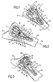
- La
figure 1 est une vue de dessus d'une plaque selon un mode de réalisation de l'invention, en position sur une extrémité de radius. - La
figure 2 montre la même plaque et la pièce de réglage amovible appartenant au système selon le mode de réalisation de l'invention plus particulièrement décrit ici. - La
figure 3 montre le système comportant de plus un bloc guide de vissage épiphysaire. - Les
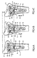
figures 4A à 4C montrent le système de lafigure 2 dans trois positions différentes, illustrant la mobilité obtenue avec l'invention dans le sens longitudinal. - Les
figures 5A à 5C montrent le système de lafigure 2 dans trois positions différentes, illustrant la mobilité obtenue avec l'invention dans le sens transversal. - La
figure 1 montre un système S comprenant une plaque 1 comportant une partie épiphysaire 2 élargie en forme de palette, pour réduction d'une fracture F entre la partie d'extrémité distale A fracturée d'un radius et le corps de l'os B. - La plaque est munie de premiers trous 3 de fixation pour premières vis d'ancrage (non représentées) par exemple huit trous sur deux rangs, de dimensions déterminées et à des emplacements spécifiques sur l'extrémité de la palette, de façon connue en elle-même.
- La plaque 1 comporte également une partie diaphysaire 4 allongée, sensiblement rectangulaire, munie de seconds trous de fixation 5, par exemple deux trous, pour secondes vis d'ancrage non représentées, ici encore de façon connue en elle-même.
- La partie diaphysaire 4 comprend de plus un orifice 6 oblong, pour le réglage de la position longitudinale de la plaque sur le radius.
- Selon le mode de réalisation de l'invention plus particulièrement décrit ici, la partie épiphysaire 2 comporte une base 7 agrandie de forme sensiblement trapézoïdale, solidaire de l'extrémité proximale 4' de la partie diaphysaire 4, comprenant un évidement 8 sensiblement triangulaire ou trapézoïdal.
- En référence à la
figure 2 , le système S comporte de plus une pièce 9 de réglage mobile comprenant une jambe 10 plus large que le trou oblong de largeur 1. La jambe 10 est munie d'une extrémité 11 plus étroite que la partie 12 de rattachement avec la barre 13 du T, ladite jambe étant donc de largeur 1' > 1 par exemple de 2 mm. - La jambe 10 est munie d'un pion (non visible sur la figure) situé du côté du trou oblong 6, avec lequel le pion coopère à glissement.
- Ce pion est par exemple formé par un petit cylindre avec col de guidage, qui vient s'emboîter dans le trou oblong comprenant une marge périphérique sur laquelle le col de guidage repose, le cylindre du pion pénétrant quant à lui dans la partie centrale du trou oblong, dans lequel il peut glisser pour permettre l'ajustage longitudinal.
- La pièce 9 présente de plus une barre 13 (la barre du T), de longueur L' dans le sens transversal, perpendiculairement à la direction ou axe longitudinal 14 du trou oblong 6 ou de la jambe 10.
- La longueur L' est supérieure à la longueur maximale L de l'évidement 8 dans le sens transversal.
- La barre 13 comporte des extrémités 15, qui sont en contact sur une distance suffisante, par exemple quelques millimètres, avec les bords périphériques 16 de l'évidement 8 de la partie épiphysaire élargie.
- Selon le mode de réalisation plus particulièrement décrit ici la barre 13 du T comprend une lumière 17, par exemple sensiblement rectangulaire, dont les extrémités sont formées par des portions de cercles.
- La longueur de cette lumière dans le sens transversal est sensiblement égale à la longueur maximale L de l'évidement 8, ladite lumière étant propre à la mise en place d'une vis de positionnement 18.
- En déplaçant la vis dans la lumière 17 du T et/ou le pion le long du trou oblong 6 cela va permettre de déplacer longitudinalement et/ou transversalement la plaque comme cela sera décrit plus précisément ci-après en référence aux
figures 4 et5 . - La
figure 3 montre quant à elle, en plus de la plaque 1 et de la pièce 9, un bloc guide 19 de vissage épiphysaire comprenant des orifices 20 cylindriques de guidage, propres à être disposés en vis à vis des trous de fixation 3 pour première vis d'ancrage. - Le système comprend également une tige 21 de positionnement et de maintien du bloc 19 en position, pour percer les trous pour vis d'ancrage.
- Les
figures 4A à 4C permettent d'illustrer le réglage longitudinal. - Ici l'intérêt de la pièce 9 en T ou glisseur, est de permettre de régler la distance entre les parties A et B avant ou après un premier vissage épiphysaire (vis 22).
- Un tel concept autorise donc l'usage d'un système unique, le degré de réglage étant lié à la longueur du trou oblong.
- La
figure 4A montre une première position dans laquelle le pion (non visible sur la figure) de la jambe du T est situé en butée sur l'extrémité 23 du trou oblong. L'extrémité distale A fracturée du radius est alors, par exemple, fixée par une ou deux vis 22 à la plaque permettant de la solidariser de façon préliminaire. - Dans cette position extrême la partie distale fracturée du radius se trouve donc à une distance x de la partie proximale de l'os.
- Au fur et à mesure que l'on déplace le pion à l'intérieur du trou oblong (voir
figure 4B ) dans le sens de la flèche 24, cela permet de rapprocher la partie fracturée qui voit la distance x se réduire, et ce jusqu'à (voirfigure 4C ) la mise en contact de la partie fracturée A avec la partie proximale B de l'os comme représentée. - On constate cependant qu'il y a alors un risque de mauvais placement latéral (décalage des côtés), qui va pouvoir être réglé grâce à l'invention, comme cela est maintenant montré en référence aux
figures 5A à 5C . - Les
figures 5A à 5C montrent successivement une position radiale 25, une position centrée 26 et une position ulnaire 27. - Grâce à la possibilité de faire déplacer la vis 18 à l'intérieur de la lumière 27, on voit en effet que on peut faire bouger latéralement la plaque 1 rendue solidaire (vis 22) de la partie fracturée A, en positionnant la partie diaphysaire allongée de telle façon qu'elle soit centrée (position 26), et ce de façon compréhensible pour l'homme de métier.
- On va maintenant décrire ci-après le fonctionnement de la mise en place d'un système d'ostéosynthèse selon l'invention.
- On fera notamment ici référence à la
figure 3 . - Après avoir inséré deux ou trois vis épiphysaires (non représentées) dans les trous 20, on procède à un premier contrôle de l'ensemble S sur l'extrémité du radius par fluroscopie.
- Si les positions des vis ne sont pas optimales, on les démonte et on bouge la plaque à l'aide du glisseur.
- Grâce à l'invention, et si après fixation des vis épiphysaires 22 on constate que la position épiphyse/diaphyse n'est pas bonne, on peut corriger la position sans démonter la zone épiphysaire.
- Pour ce faire, après desserrage de la vis 18 de la pièce 13 ou glisseur on déplace la plaque autour de cette vis sur les deux axes longitudinaux 14, et transversaux (perpendiculaire à l'axe 14) jusqu'au bon positionnement des parties A et B entre elles.
- On introduit ensuite les autres vis épiphysaire après avoir donc trouvé la bonne position de la plaque et on serre les deux vis diaphysaires proximales.
- Il ne reste plus alors qu'à démonter le glisseur, puis à mettre la dernière vis diaphysaire dans le trou oblong.
- On voit que l'intérêt du glisseur est notamment de permettre le réglage de la plaque, avant ou après un premier vissage épiphysaire.
- Le degré de réglage est lié à la longueur du trou oblong 6 pour la mobilité longitudinale, et à la longueur de la lumière 17 de la barre du T pour la mobilité latérale.
- On aura compris que la pièce en T ou glisseur est uniquement destinée à un usage préopératoire et doit donc être retirée en fin d'opération.
- Comme il va de soi et comme il résulte également de ce qui précède, la présente invention n'est pas limitée aux modes de réalisation plus particulièrement décrits. Elle en embrasse au contraire toutes les variantes et notamment celles où la pièce en T est par exemple triangulaire.
Claims (8)
- Système d'ostéosynthèse (S) pour réduction d'une fracture distale (F) d'un os allongé, comprenant une plaque (1) comportant une partie épiphysaire (2) élargie en forme de palette solidaire d'une partie diaphysaire (4) allongée, lesdites parties étant munies de trous de fixation (3, 5) pour vis d'ancrage, ladite partie diaphysaire (4) comprenant un orifice oblong (6) pour réglage de la position longitudinale de la plaque sur l'os,
caractérisé en ce que la partie épiphysaire (2) présente une base (7) agrandie comprenant un évidement (8) sensiblement triangulaire ou trapézoïdal,
et en ce que le système (S) comporte de plus une pièce (9) de réglage amovible de la plaque sur l'os comprenant une première partie (10) plus large que le trou oblong (6) munie d'un pion agencé pour être inséré dans ledit trou oblong avec lequel il coopère à glissement, et une deuxième partie (13) de longueur L' supérieure à la longueur L de l'évidement et dont les extrémités (15) sont propres à être en contact avec les bords (16) de l'évidement de la partie épiphysaire lorsque le pion est inséré dans le trou oblong, ladite deuxième partie étant munie d'une lumière (17) allongée en vis à vis de l'évidement, ladite lumière (17) étant propre à la mise en place d'une vis (18) de positionnement, de sorte qu'en déplaçant la vis dans la lumière de la pièce de réglage et/ou le pion le long du trou oblong on déplace longitudinalement et/ou transversalement la plaque. - Système selon la revendication 1 caractérisé en ce que la pièce de réglage amovible est en forme de T, la première partie formant la jambe du T et la deuxième partie la barre du T.
- Système d'osthéosynthèse selon l'une quelconque des revendications précédentes, caractérisé en ce que la partie diaphysaire (4) est sensiblement allongée dans un premier plan et la partie épiphysaire (2) est sensiblement située dans un deuxième plan incliné par rapport au plan de ladite partie diaphysaire.
- Système selon la revendication 3, caractérisé en ce que l'inclinaison entre le plan de la partie epiphysaire et le plan de la partie diaphysaire est compris entre 5° et 15°.
- Système selon l'une quelconque des revendications précédentes, caractérisé en ce que le trou oblong (6) est de longueur comprise entre 6 mm et 12 mm.
- Système selon l'une quelconque des revendications précédentes, caractérisé en ce que la lumière (17) est de longueur comprise entre 12 mm et 14 mm.
- Système selon l'une quelconque des revendications précédentes, caractérisé en ce que l'évidement sensiblement triangulaire présente une surface comprise entre la moitié et les 4/5eme de la base agrandie de la partie épiphysaire.
- Système selon l'une quelconque des revendications précédentes, caractérisé en ce que il comporte de plus un bloc (19) guide de vissage épiphysaire comprenant des orifices (20) de guidage propres à être disposés en vis à vis des trous de fixation des vis d'ancrage de ladite partie épiphysaire.
Applications Claiming Priority (1)
| Application Number | Priority Date | Filing Date | Title |
|---|---|---|---|
| FR1000936A FR2956971B1 (fr) | 2010-03-08 | 2010-03-08 | Systeme d'osteosynthese a plaque |
Publications (2)
| Publication Number | Publication Date |
|---|---|
| EP2364659A1 EP2364659A1 (fr) | 2011-09-14 |
| EP2364659B1 true EP2364659B1 (fr) | 2012-10-10 |
Family
ID=42289822
Family Applications (2)
| Application Number | Title | Priority Date | Filing Date |
|---|---|---|---|
| EP11001208A Not-in-force EP2364659B1 (fr) | 2010-03-08 | 2011-02-15 | Systeme d'osteosynthese a plaque |
| EP11714350.3A Active EP2544612B1 (fr) | 2010-03-08 | 2011-03-07 | Systeme d'osteosynthese a plaque |
Family Applications After (1)
| Application Number | Title | Priority Date | Filing Date |
|---|---|---|---|
| EP11714350.3A Active EP2544612B1 (fr) | 2010-03-08 | 2011-03-07 | Systeme d'osteosynthese a plaque |
Country Status (7)
| Country | Link |
|---|---|
| US (2) | US8419776B2 (fr) |
| EP (2) | EP2364659B1 (fr) |
| AU (1) | AU2011225965B2 (fr) |
| CA (1) | CA2791839A1 (fr) |
| ES (1) | ES2397215T3 (fr) |
| FR (1) | FR2956971B1 (fr) |
| WO (1) | WO2011110756A1 (fr) |
Families Citing this family (19)
| Publication number | Priority date | Publication date | Assignee | Title |
|---|---|---|---|---|
| EP2224868B1 (fr) * | 2007-11-21 | 2014-07-30 | Globus Medical, Inc. | Système de stabilisation de colonne cervicale avec plaques extensibles |
| US10188438B2 (en) * | 2013-04-24 | 2019-01-29 | Skeletal Dynamics, Llc | Bone plate with transversal slots for receiving a fastener |
| US8523861B2 (en) * | 2010-08-30 | 2013-09-03 | Biomet Manufacturing, Llc | Method and apparatus for osteosynthesis |
| US8518042B2 (en) * | 2010-10-19 | 2013-08-27 | Biomet Manufacturing, Llc | Orthopedic plate assembly for a distal radius having re-contouring features and method for using same |
| EP2872073B1 (fr) | 2012-07-12 | 2018-09-19 | Exsomed Holding Company LLC | Dispositif de stabilisation de métacarpien |
| US9028498B2 (en) | 2013-03-14 | 2015-05-12 | Innovasis, Inc. | Modular bone fixation plate assembly |
| US11259849B2 (en) | 2013-10-02 | 2022-03-01 | ExsoMed Corporation | Full wrist fusion device |
| JP6594946B2 (ja) | 2014-07-03 | 2019-10-23 | アキュームド・エルエルシー | 移動可能な継手を備える骨プレート |
| JP6571023B2 (ja) | 2015-02-18 | 2019-09-04 | ビーダーマン・テクノロジーズ・ゲゼルシャフト・ミット・ベシュレンクテル・ハフツング・ウント・コンパニー・コマンディートゲゼルシャフトBiedermann Technologies Gmbh & Co. Kg | 骨プレートおよび骨プレートアセンブリ |
| US10363145B2 (en) * | 2015-02-23 | 2019-07-30 | Amendia, Inc. | Lateral plate and spinal implant system and method |
| WO2016186847A1 (fr) * | 2015-05-19 | 2016-11-24 | Exsomed International IP, LLC | Plaque pour radius distal |
| US10245091B2 (en) | 2015-12-30 | 2019-04-02 | Exsomed Holding Company, Llc | Dip fusion spike screw |
| US11147604B2 (en) | 2016-01-12 | 2021-10-19 | ExsoMed Corporation | Bone stabilization device |
| US10194923B2 (en) | 2016-05-10 | 2019-02-05 | Exsomed International IP, LLC | Tool for percutaneous joint cartilage destruction and preparation for joint fusion |
| ES3062806T3 (en) | 2016-10-04 | 2026-04-14 | Acumed Llc | Fixation system for hoffa fractures |
| US11147681B2 (en) | 2017-09-05 | 2021-10-19 | ExsoMed Corporation | Small bone angled compression screw |
| EP4477166A3 (fr) | 2017-09-05 | 2025-03-19 | ExsoMed Corporation | Clou fileté intramédullaire pour fixation corticale radiale |
| US11191645B2 (en) | 2017-09-05 | 2021-12-07 | ExsoMed Corporation | Small bone tapered compression screw |
| US20260060728A1 (en) * | 2024-09-02 | 2026-03-05 | Taipei Medical University | Bone plate for treating shoulder joint injury |
Family Cites Families (156)
| Publication number | Priority date | Publication date | Assignee | Title |
|---|---|---|---|---|
| FR742618A (fr) | 1933-03-10 | |||
| US2526959A (en) * | 1947-07-01 | 1950-10-24 | Frank A Lorenzo | Fracture reduction apparatus |
| US2580821A (en) * | 1950-10-21 | 1952-01-01 | Nicola Toufick | Spring impactor bone plate |
| US3304937A (en) * | 1964-07-24 | 1967-02-21 | Jr George R Callender | Derotation brace for tibia deformities |
| US3386437A (en) * | 1966-01-14 | 1968-06-04 | Richard Mfg Company | Compression device for use with a bone fracture plate |
| US3488779A (en) * | 1967-09-27 | 1970-01-13 | Robert W Christensen | Orthopedic prosthetic appliances for attachment to bone |
| US3489143A (en) * | 1967-12-15 | 1970-01-13 | William X Halloran | Convertible hip pin |
| US3604414A (en) * | 1968-08-29 | 1971-09-14 | Nicomedes Borges | Bone setting device |
| US3842825A (en) * | 1973-11-12 | 1974-10-22 | R Wagner | Hip fixation device |
| FR2254298A1 (en) | 1973-12-18 | 1975-07-11 | Chatin Robert | Osteosynthesis plate guide device - has eccentric screw guide members in fracture clamping plate |
| US3900025A (en) * | 1974-04-24 | 1975-08-19 | Jr Walter P Barnes | Apparatus for distracting or compressing longitudinal bone segments |
| FR2367479A1 (fr) | 1976-10-18 | 1978-05-12 | Bazelaire Eric De | Plaque chirurgicale d'osteosynthese a flexibilite variable |
| FR2405706A1 (fr) | 1977-10-14 | 1979-05-11 | Dayan Robert | Plaque d'osteosynthese pour le traitement chirurgical des fractures de l'extremite inferieure de l'humerus |
| FR2405705A1 (fr) | 1977-10-14 | 1979-05-11 | Dayan Robert | Plaque d'osteosynthese pour le traitement chirurgical des fractures de l'extremite superieure du tibia |
| FR2406429A1 (fr) | 1977-10-21 | 1979-05-18 | Dayan Robert | Plaque d'osteosynthese destinee au traitement chirurgical des fractures de l'extremite inferieure du tibia |
| DE3043566A1 (de) | 1980-11-14 | 1982-07-01 | Mecron Medizinische Produkte Gmbh, 1000 Berlin | Vorrichtung zum zusammenhalten der teile eines menschlichen schulter-eck-gelenkes |
| CA1178150A (fr) * | 1981-06-18 | 1984-11-20 | Emmanuel Anapliotis | Clou pour la reparation d'une fracture du femur |
| US4454876A (en) * | 1982-05-25 | 1984-06-19 | University Of Pittsburgh | Pelvic fixation plate and method of implanting same |
| SU1130332A1 (ru) | 1983-01-26 | 1984-12-23 | Киевский Медицинский Институт Им.Акад.А.А.Богомольца | Устройство дл компрессионного остеосинтеза |
| SU1223901A1 (ru) | 1983-10-19 | 1986-04-15 | Новокузнецкий Государственный Ордена Трудового Красного Знамени Институт Усовершенствования Врачей | Устройство дл остеосинтеза |
| PL147580B1 (en) * | 1986-04-14 | 1989-06-30 | Plate for uniting epiphysis and diaphysis of broken bone | |
| US4776330A (en) | 1986-06-23 | 1988-10-11 | Pfizer Hospital Products Group, Inc. | Modular femoral fixation system |
| DE8808123U1 (de) * | 1988-06-24 | 1988-09-22 | Herzberg, Wolfgang, Dr. med., 2000 Wedel | Laschenschraube für die Osteosynthese pertrochantärer Frakturen |
| FR2637028B1 (fr) | 1988-09-28 | 1990-12-21 | Proteor Sa | Systeme d'assemblage de deux organes rigides plans et utilisation pour l'assemblage d'elements d'armature d'un corset orthopedique |
| SU1683724A1 (ru) | 1989-01-09 | 1991-10-15 | Военно-Медицинская Краснознаменная Академия Им.С.М.Кирова | Устройство дл остеосинтеза при остеотомии бедренной кости |
| US5474553A (en) * | 1989-04-18 | 1995-12-12 | Rainer Baumgart | System for setting tubular bone fractures |
| DE3923995A1 (de) | 1989-07-20 | 1991-01-31 | Lutz Biedermann | Stabilisierungselement fuer knochen |
| US5006120A (en) * | 1989-10-10 | 1991-04-09 | Carter Peter R | Distal radial fracture set and method for repairing distal radial fractures |
| SU1711859A1 (ru) | 1989-11-09 | 1992-02-15 | Новокузнецкий государственный институт усовершенствования врачей | Устройство дл компрессионного остеосинтеза |
| SU1734715A1 (ru) | 1990-02-26 | 1992-05-23 | Военно-Медицинская Краснознаменная Академия Им.С.М.Кирова | Устройство дл фиксации шейки бедренной кости после ротационной остеотомии |
| DE9010051U1 (de) | 1990-07-02 | 1991-10-31 | Waldemar Link Gmbh & Co, 2000 Hamburg | Knochenplatte für den distalen Oberarmknochen |
| CH686222A5 (de) * | 1991-05-30 | 1996-02-15 | Synthes Ag | Trochanterstabilisierungsvorrichtung. |
| US5304180A (en) * | 1992-01-17 | 1994-04-19 | Slocum D Barclay | Tibial osteotomy fixation plate |
| GB9206018D0 (en) * | 1992-03-19 | 1992-04-29 | Dall Desmond Meiring | Bone fixation system |
| US5197966A (en) * | 1992-05-22 | 1993-03-30 | Sommerkamp T Greg | Radiodorsal buttress blade plate implant for repairing distal radius fractures |
| US5324290A (en) * | 1992-09-24 | 1994-06-28 | Danek Medical, Inc. | Anterior thoracolumbar plate |
| DE9216565U1 (de) * | 1992-12-04 | 1994-03-31 | Waldemar Link GmbH & Co, 22339 Hamburg | Vorrichtung zum Verbinden von Knochenteilen mittels einer Knochenplatte |
| US5531745A (en) * | 1993-03-11 | 1996-07-02 | Danek Medical, Inc. | System for stabilizing the spine and reducing spondylolisthesis |
| US5487743A (en) * | 1994-02-15 | 1996-01-30 | Sofamore, S.N.C. | Anterior dorso-lumbar spinal osteosynthesis instrumentation for the correction of kyphosis |
| US5586985A (en) * | 1994-10-26 | 1996-12-24 | Regents Of The University Of Minnesota | Method and apparatus for fixation of distal radius fractures |
| DE29501880U1 (de) * | 1995-02-06 | 1995-05-24 | Karl Leibinger Medizintechnik GmbH & Co. KG, 78570 Mühlheim | Vorrichtung zur Knochenverlängerung |
| US5749872A (en) * | 1995-09-08 | 1998-05-12 | Ace Medical Company | Keyed/keyless barrel for bone plates |
| US6007535A (en) * | 1996-01-03 | 1999-12-28 | John M. Rayhack | Multi-plane bone distraction system |
| JP3688380B2 (ja) | 1996-02-06 | 2005-08-24 | 日本特殊陶業株式会社 | 骨補填材用固定具 |
| US5868749A (en) * | 1996-04-05 | 1999-02-09 | Reed; Thomas M. | Fixation devices |
| US6096040A (en) * | 1996-06-14 | 2000-08-01 | Depuy Ace Medical Company | Upper extremity bone plates |
| US5827286A (en) * | 1997-02-14 | 1998-10-27 | Incavo; Stephen J. | Incrementally adjustable tibial osteotomy fixation device and method |
| US5853413A (en) * | 1997-04-18 | 1998-12-29 | Bristol-Myers Squibb Company | Wrist fusion plate |
| FR2766353B1 (fr) * | 1997-07-28 | 1999-11-26 | Dimso Sa | Implant, notamment plaque anterieure cervicale |
| US5928234A (en) * | 1997-10-10 | 1999-07-27 | Manspeizer; Sheldon | External fixture for tracking motion of a joint |
| US5951557A (en) * | 1997-12-30 | 1999-09-14 | Luter; Dennis W. | Bone plate |
| US6129728A (en) * | 1998-02-18 | 2000-10-10 | Walter Lorenz Surgical, Inc. | Method and apparatus for mandibular osteosynthesis |
| US6325803B1 (en) * | 1998-02-18 | 2001-12-04 | Walter Lorenz Surgical, Inc. | Method and apparatus for mandibular osteosynthesis |
| US6183475B1 (en) * | 1998-12-18 | 2001-02-06 | Sulzer Orthopedics Inc. | Distal femoral osteotomy system and method |
| JP2002543915A (ja) * | 1999-05-14 | 2002-12-24 | ジンテーズ アクチエンゲゼルシャフト クール | 回転ジョイントを有する骨固定装置 |
| JP2001037767A (ja) * | 1999-08-02 | 2001-02-13 | Kyowa Tokei Kogyo Kk | 骨調整具 |
| ES2211583T3 (es) | 1999-09-13 | 2004-07-16 | Synthes Ag Chur | Sistema de placa osea. |
| US7857838B2 (en) * | 2003-03-27 | 2010-12-28 | Depuy Products, Inc. | Anatomical distal radius fracture fixation plate |
| US6712820B2 (en) * | 2000-02-01 | 2004-03-30 | Hand Innovations, Inc. | Fixation plate system for dorsal wrist fracture fixation |
| US6767351B2 (en) * | 2000-02-01 | 2004-07-27 | Hand Innovations, Inc. | Fixation system with multidirectional stabilization pegs |
| US6358250B1 (en) * | 2000-02-01 | 2002-03-19 | Hand Innovations, Inc. | Volar fixation system |
| US7695502B2 (en) | 2000-02-01 | 2010-04-13 | Depuy Products, Inc. | Bone stabilization system including plate having fixed-angle holes together with unidirectional locking screws and surgeon-directed locking screws |
| US6893444B2 (en) * | 2000-02-01 | 2005-05-17 | Hand Innovations, Llc | Bone fracture fixation systems with both multidirectional and unidirectional stabilization pegs |
| US20040153073A1 (en) | 2000-02-01 | 2004-08-05 | Hand Innovations, Inc. | Orthopedic fixation system including plate element with threaded holes having divergent axes |
| US6866665B2 (en) * | 2003-03-27 | 2005-03-15 | Hand Innovations, Llc | Bone fracture fixation system with subchondral and articular surface support |
| US6440135B2 (en) * | 2000-02-01 | 2002-08-27 | Hand Innovations, Inc. | Volar fixation system with articulating stabilization pegs |
| US7282053B2 (en) * | 2003-03-27 | 2007-10-16 | Depuy Products, Inc. | Method of using fracture fixation plate for performing osteotomy |
| WO2001062136A2 (fr) | 2000-02-24 | 2001-08-30 | Stryker Instruments | Plaques, elements de fixation et outils bioabsorbables et procede d'utilisation associe |
| US6283969B1 (en) * | 2000-03-10 | 2001-09-04 | Wright Medical Technology, Inc. | Bone plating system |
| USD443060S1 (en) * | 2000-06-01 | 2001-05-29 | Bristol-Myers Squibb Company | Bone plate |
| US6740088B1 (en) * | 2000-10-25 | 2004-05-25 | Sdgi Holdings, Inc. | Anterior lumbar plate and method |
| US6503250B2 (en) * | 2000-11-28 | 2003-01-07 | Kamaljit S. Paul | Bone support assembly |
| US6402756B1 (en) * | 2001-02-15 | 2002-06-11 | Third Millennium Engineering, Llc | Longitudinal plate assembly having an adjustable length |
| US6666867B2 (en) * | 2001-02-15 | 2003-12-23 | Fast Enetix, Llc | Longitudinal plate assembly having an adjustable length |
| US6929646B2 (en) * | 2001-04-04 | 2005-08-16 | Integra Signature Technologies, Inc. | Implantable bone fracture reduction apparatus having a polymeric applicator |
| US20020156474A1 (en) | 2001-04-20 | 2002-10-24 | Michael Wack | Polyaxial locking plate |
| US20050234458A1 (en) * | 2004-04-19 | 2005-10-20 | Huebner Randall J | Expanded stabilization of bones |
| US20050240187A1 (en) * | 2004-04-22 | 2005-10-27 | Huebner Randall J | Expanded fixation of bones |
| US8231662B2 (en) | 2006-10-17 | 2012-07-31 | Acumed Llc | Bone fixation with a strut-stabilized bone plate |
| US7537604B2 (en) * | 2002-11-19 | 2009-05-26 | Acumed Llc | Bone plates with slots |
| SI1389963T1 (sl) * | 2001-05-28 | 2006-10-31 | Synthes Ag | Kostna ploscica za fiksiranje zlomov proksimalnega humerusa |
| US7186256B2 (en) * | 2001-06-04 | 2007-03-06 | Warsaw Orthopedic, Inc. | Dynamic, modular, single-lock anterior cervical plate system having assembleable and movable segments |
| US7316687B2 (en) * | 2001-08-24 | 2008-01-08 | Zimmer Technology, Inc. | Blade plate and instruments |
| US6508819B1 (en) * | 2001-08-28 | 2003-01-21 | Hand Innovations, Inc. | Method of dorsal wrist fracture fixation |
| US6652530B2 (en) * | 2001-09-19 | 2003-11-25 | The University Of Hong Kong | Fixation device |
| US6793659B2 (en) * | 2001-10-12 | 2004-09-21 | Regents Of The University Of Minnesota | Intramedullary rod for wrist fixation |
| US6755831B2 (en) * | 2001-11-30 | 2004-06-29 | Regents Of The University Of Minnesota | Wrist surgery devices and techniques |
| US20030153918A1 (en) * | 2002-02-14 | 2003-08-14 | Putnam Matthew D. | Volar fixation plate |
| US20050065521A1 (en) | 2002-02-22 | 2005-03-24 | Steger Shon D. | Method and apparatus for bone fracture fixation |
| US7780710B2 (en) | 2004-01-23 | 2010-08-24 | Depuy Products, Inc. | System for stabilization of fractures of convex articular bone surfaces including subchondral support structure |
| US20040116930A1 (en) * | 2002-06-10 | 2004-06-17 | O'driscoll Shawn W. | Bone plates |
| US20030233093A1 (en) * | 2002-06-13 | 2003-12-18 | Randall Moles | Osteogenic distraction device |
| US7179260B2 (en) | 2003-09-29 | 2007-02-20 | Smith & Nephew, Inc. | Bone plates and bone plate assemblies |
| KR20050083916A (ko) * | 2002-11-19 | 2005-08-26 | 어큠드 엘엘씨 | 변형가능한 뼈 평판 |
| KR101081269B1 (ko) | 2002-11-19 | 2011-11-08 | 어큠드 엘엘씨 | 조정가능한 본 플레이트 |
| WO2004062482A2 (fr) * | 2003-01-10 | 2004-07-29 | Abdou Samy M | Systeme d'attelle pour la fixation et la reduction des os et procede d'implantation correspondant |
| US7250053B2 (en) | 2003-03-27 | 2007-07-31 | Depuy Products, Inc. | Low profile distal radius fracture fixation plate |
| US20040193155A1 (en) * | 2003-03-27 | 2004-09-30 | Hand Innovations, Inc. | Fracture fixation plate with particular plate hole and fastener engagement and methods of using the same |
| US7635381B2 (en) | 2003-03-27 | 2009-12-22 | Depuy Products, Inc. | Anatomical distal radius fracture fixation plate with fixed-angle K-wire holes defining a three-dimensional surface |
| US7294130B2 (en) | 2003-03-27 | 2007-11-13 | Depuy Products, Inc. | Distal radius fracture fixation plate having K-wire hole structured to fix a K-wire in one dimension relative to the plate |
| DE20309361U1 (de) | 2003-04-11 | 2003-09-18 | Königsee Implantate und Instrumente zur Ostheosynthese GmbH, 07426 Königsee | Osteosynthese, insbesondere winkelstabile Radiusplatte, zur operativen Versorgung von Knochenfrakturen |
| US7951176B2 (en) | 2003-05-30 | 2011-05-31 | Synthes Usa, Llc | Bone plate |
| DE10326643A1 (de) | 2003-06-11 | 2004-12-30 | Mückter, Helmut, Dr. med. Dipl.-Ing. | Osteosyntheseplatte oder vergleichbares Implantat nebst Kugelhülse |
| US6945975B2 (en) | 2003-07-07 | 2005-09-20 | Aesculap, Inc. | Bone fixation assembly and method of securement |
| WO2005037114A1 (fr) | 2003-10-17 | 2005-04-28 | Acumed Llc | Systemes de fixation du radius distal |
| US7867260B2 (en) | 2003-11-05 | 2011-01-11 | Koenigsee Implantate Und Instrumente Zur Osteosynthese Gmbh | Plate used to stabilise distal radius fractures |
| CA2546050C (fr) | 2003-11-18 | 2012-08-28 | Synthes Gmbh | Assemblage de plaques d'osteosynthese |
| JP4790634B2 (ja) | 2004-01-23 | 2011-10-12 | デピュイ・プロダクツ・インコーポレイテッド | 軟骨下支持構造を有する、凸状関節骨面の骨折を固定するためのシステム |
| EP1713410B1 (fr) | 2004-01-23 | 2010-11-24 | Depuy Products, Inc. | système pour la consolidation d'une fracture de l'humérus proximal comprenant une tige bloquée en rotation et un support transversal rigide |
| US8574268B2 (en) | 2004-01-26 | 2013-11-05 | DePuy Synthes Product, LLC | Highly-versatile variable-angle bone plate system |
| US7740649B2 (en) | 2004-02-26 | 2010-06-22 | Pioneer Surgical Technology, Inc. | Bone plate system and methods |
| AU2004320254B2 (en) | 2004-06-01 | 2010-08-12 | Synthes Gmbh | Osteosynthesis plate |
| US20060173458A1 (en) | 2004-10-07 | 2006-08-03 | Micah Forstein | Bone fracture fixation system |
| US20060089648A1 (en) | 2004-10-27 | 2006-04-27 | Masini Michael A | Versatile bone plate systems particularly suited to minimally invasive surgical procedures |
| US7604657B2 (en) | 2005-09-19 | 2009-10-20 | Depuy Products, Inc. | Bone fixation plate with complex suture anchor locations |
| US8062296B2 (en) * | 2005-03-17 | 2011-11-22 | Depuy Products, Inc. | Modular fracture fixation plate system with multiple metaphyseal and diaphyseal plates |
| US8394130B2 (en) | 2005-03-17 | 2013-03-12 | Biomet C.V. | Modular fracture fixation system |
| US7648508B2 (en) | 2004-11-30 | 2010-01-19 | Stryker Trauma S.A. | Bone plating implants, instruments and methods |
| US8118846B2 (en) | 2005-01-28 | 2012-02-21 | Orthohelix Surgical Designs, Inc. | Orthopedic plates for use in clavicle repair and methods for their use |
| FI119969B (fi) | 2005-05-06 | 2009-05-29 | Inion Ltd | Levy ja järjestelmä luuosien kiinnittämiseksi |
| FR2886535B1 (fr) | 2005-06-06 | 2008-04-25 | Surfix Technologies Sa | Dispositif destine a etre arrime a un support, piece d'assemblage pour un tel dispositif et procede d'arrimage d'un dispositif a un support |
| DE202005019277U1 (de) * | 2005-10-14 | 2006-02-02 | Stryker Leibinger Gmbh & Co. Kg | Knochenplatte mit wenigstens zwei Langlöchern und Knochenplattensystem |
| KR101246113B1 (ko) | 2005-10-25 | 2013-03-20 | 앤썸 오르소패딕스, 엘엘씨 | 뼈 고정 어셈블리 및 거기에서 사용되는 부싱 및 스크루 |
| JP2007151674A (ja) * | 2005-12-01 | 2007-06-21 | Hidetoshi Onoe | 骨プレート |
| US7914562B2 (en) | 2006-02-27 | 2011-03-29 | Zielinski Steven C | Method and apparatus for lateral reduction and fusion of the spine |
| US8021402B2 (en) | 2006-03-07 | 2011-09-20 | Orthohelix Surgical Designs, Inc. | Distal radius plate |
| US8808334B2 (en) | 2006-03-07 | 2014-08-19 | Orthohelix Surgical Designs, Inc. | Orthopedic plate |
| US8926675B2 (en) | 2006-04-11 | 2015-01-06 | Biomet Manufacturing, Llc | Contoured bone plate |
| US8257355B2 (en) | 2006-06-07 | 2012-09-04 | Spinefrontier Inc. | Methods and devices for static or dynamic spine stabilization |
| US8398687B2 (en) | 2006-12-06 | 2013-03-19 | Amei Technologies, Inc. | Volar plate fixation device |
| US20080183172A1 (en) | 2007-01-26 | 2008-07-31 | Zimmer Technology, Inc. | Retention feature for plate guides |
| US7603192B2 (en) | 2007-02-13 | 2009-10-13 | Orthohelix Surgical Designs, Inc. | Method of making orthopedic implants and the orthopedic implants |
| US20100063505A1 (en) | 2007-03-22 | 2010-03-11 | Robert Frigg | Bone plate |
| US7857837B2 (en) | 2007-06-04 | 2010-12-28 | Lieponis Jonas V | Adjustable spinal system |
| FR2917596B1 (fr) | 2007-06-21 | 2010-06-18 | Newdeal | Kit de fixation a usage medical ou chirurgical |
| DE102007036943B4 (de) | 2007-08-04 | 2014-12-31 | Zimmer Gmbh | Fußchirurgie-Knochenplatte |
| US7867263B2 (en) | 2007-08-07 | 2011-01-11 | Transcorp, Inc. | Implantable bone plate system and related method for spinal repair |
| US8343154B2 (en) | 2007-09-26 | 2013-01-01 | Biomet C.V. | Modular bone plate system |
| ATE527949T1 (de) | 2007-11-02 | 2011-10-15 | Depuy Products Inc | Fixiersystem für ellbogenbruch |
| US8317842B2 (en) | 2007-11-30 | 2012-11-27 | Biomet C.V. | Distal tibia plating system |
| US20090326591A1 (en) | 2008-01-29 | 2009-12-31 | Spencer Jr Edwin E | System and method to position and secure fractured bones |
| FR2928259B1 (fr) | 2008-03-07 | 2011-04-22 | D L P Sarl | Materiel pour la reduction d'une fracture,en particulier d'une fracture de radius distal |
| US8915918B2 (en) | 2008-05-02 | 2014-12-23 | Thomas James Graham | Bone plate system for bone restoration and methods of use thereof |
| US8652179B2 (en) | 2008-05-02 | 2014-02-18 | The Cleveland Clinic Foundation | Bone plate extender and extension system for bone restoration and methods of use thereof |
| US8628533B2 (en) | 2008-05-08 | 2014-01-14 | The Cleveland Clinic Foundation | Bone plate with reduction aids and methods of use thereof |
| US8545539B2 (en) | 2008-05-12 | 2013-10-01 | Edwin E. Spencer | Proximal humeral fracture reduction and fixation device |
| US20090299370A1 (en) | 2008-05-29 | 2009-12-03 | Kiester P Douglas | Dynamization of fixed screw fracture plates |
| US9072555B2 (en) | 2008-07-21 | 2015-07-07 | Arthrex, Inc. | Carbon fiber reinforced peek bone plate with titanium fixation screws |
| US8262707B2 (en) | 2008-07-31 | 2012-09-11 | Biomet C.V. | Periarticular bone plate with biplanar offset head member |
| US8257405B2 (en) | 2008-07-31 | 2012-09-04 | Biomet C.V. | Periarticular bone plate with biplanar offset head member |
| US20100057133A1 (en) | 2008-08-26 | 2010-03-04 | Simon William H | Tibia-talus-calcaneus (T-T-C) locking plate |
| US8231625B2 (en) | 2008-09-03 | 2012-07-31 | The Cleveland Clinic Foundation | Modular bone fixation device for treatment of fractures and related methods |
| US20100152783A1 (en) | 2008-12-11 | 2010-06-17 | Veterinary Implants Direct, Llc | Universal Surgical Plate with 30 Degree Compression Angle |
| US20100179599A1 (en) | 2009-01-12 | 2010-07-15 | Guillaume Derouet | Device for reducing a bone fracture, in particular a fracture at the bone epiphyses |
| US8834532B2 (en) | 2009-07-07 | 2014-09-16 | Zimmer Gmbh | Plate for the treatment of bone fractures |
| JP2013505071A (ja) | 2009-09-18 | 2013-02-14 | デピュイ・プロダクツ・インコーポレイテッド | 使い捨て整形外科キット及び構成要素 |
-
2010
- 2010-03-08 FR FR1000936A patent/FR2956971B1/fr not_active Expired - Fee Related
- 2010-11-18 US US12/948,795 patent/US8419776B2/en active Active
-
2011
- 2011-02-15 ES ES11001208T patent/ES2397215T3/es active Active
- 2011-02-15 EP EP11001208A patent/EP2364659B1/fr not_active Not-in-force
- 2011-03-07 EP EP11714350.3A patent/EP2544612B1/fr active Active
- 2011-03-07 WO PCT/FR2011/000123 patent/WO2011110756A1/fr not_active Ceased
- 2011-03-07 CA CA2791839A patent/CA2791839A1/fr not_active Abandoned
- 2011-03-07 AU AU2011225965A patent/AU2011225965B2/en not_active Ceased
-
2013
- 2013-03-12 US US13/796,256 patent/US8894650B2/en active Active
Also Published As
| Publication number | Publication date |
|---|---|
| US8419776B2 (en) | 2013-04-16 |
| US20130197519A1 (en) | 2013-08-01 |
| WO2011110756A1 (fr) | 2011-09-15 |
| US8894650B2 (en) | 2014-11-25 |
| CA2791839A1 (fr) | 2011-09-15 |
| EP2544612B1 (fr) | 2015-08-05 |
| EP2544612A1 (fr) | 2013-01-16 |
| US20110218533A1 (en) | 2011-09-08 |
| ES2397215T3 (es) | 2013-03-05 |
| FR2956971A1 (fr) | 2011-09-09 |
| AU2011225965B2 (en) | 2014-07-10 |
| EP2364659A1 (fr) | 2011-09-14 |
| FR2956971B1 (fr) | 2012-03-02 |
| AU2011225965A1 (en) | 2012-09-27 |
Similar Documents
| Publication | Publication Date | Title |
|---|---|---|
| EP2544612B1 (fr) | Systeme d'osteosynthese a plaque | |
| CA2321895C (fr) | Dispositif orthopedique monolateral de fixation externe | |
| EP1113758B1 (fr) | Dispositif d'osteosynthese rachidienne posterieure | |
| EP2544613B1 (fr) | Plaque d'osteosynthese articulee | |
| EP2991572B1 (fr) | Dispositif d'ostéotomie, en particulier pour la réalisation du scarf extrême dans le traitement de l'hallux valgus sévère. | |
| FR2846870A1 (fr) | Materiel d'osteosynthese pour le traitement d'un cubitus"long" | |
| EP1489980B1 (fr) | Systeme d'osteosynthese rachidienne | |
| EP3143955A1 (fr) | Implant orthopedique sous forme d'une plaque destinee a etre fixee entre deux parties d'os | |
| WO2012131246A1 (fr) | Plaque d'ostéosynthèse | |
| FR2908627A1 (fr) | Dispositif prothetique ou d'osteosynthese a olive fendue | |
| WO1995028887A1 (fr) | Materiel pour la correction de deformations des os longs | |
| FR2807313A1 (fr) | Ensemble retracteur orthopedique de tissus mous notamment pour la chirurgie du rachis | |
| FR2795621A1 (fr) | Plaque d'osteosynthese vertebrale, systeme d'osteosynthese et procede mettant en oeuvre une telle plaque | |
| WO2012069727A1 (fr) | Clou d'ostéosynthèse | |
| EP3166521B1 (fr) | Implant et kit chirurgical pour maintenir en position des corps osseux d'un patient les uns par rapport aux autres | |
| FR2939639A1 (fr) | Prothese d'epaule. | |
| FR2930424A1 (fr) | Dispositif de reduction d'une fracture entre la tete epiphysaire et la diaphyse d'un os long, notamment d'une fracture humerale proximale. | |
| FR2945436A1 (fr) | Instrumentation chirurgicale de distraction osseuse de l'epaule | |
| WO2015136203A1 (fr) | Systeme d'osteosynthese comprenant des moyens de redressement d'un element d'ancrage osseux par rapport a une tete de vis et vis d'ancrage mise en oeuvre dans un tel systeme | |
| FR3008301A1 (fr) | Dispositif pour la distraction d'un tissu | |
| FR2956970A1 (fr) | Gamme de clous intramedullaires humeraux et ancillaire pour la pose de clous intramedullaires appartenant a ladite gamme | |
| WO2025224113A1 (fr) | Système fixateur externe élastique, et ensemble doté d'un tel système | |
| EP3282981B1 (fr) | Système minimalement invasif de correction dynamique d'une déformation rachidienne | |
| FR3093283A1 (fr) | Ensemble d’ostéosynthèse pour fracture d’un humérus | |
| FR2920960A1 (fr) | Plaque d'osteosynthese pour fracture de l'extremite inferieure du radius |
Legal Events
| Date | Code | Title | Description |
|---|---|---|---|
| PUAI | Public reference made under article 153(3) epc to a published international application that has entered the european phase |
Free format text: ORIGINAL CODE: 0009012 |
|
| 17P | Request for examination filed |
Effective date: 20110215 |
|
| AK | Designated contracting states |
Kind code of ref document: A1 Designated state(s): AL AT BE BG CH CY CZ DE DK EE ES FI FR GB GR HR HU IE IS IT LI LT LU LV MC MK MT NL NO PL PT RO RS SE SI SK SM TR |
|
| AX | Request for extension of the european patent |
Extension state: BA ME |
|
| GRAP | Despatch of communication of intention to grant a patent |
Free format text: ORIGINAL CODE: EPIDOSNIGR1 |
|
| GRAS | Grant fee paid |
Free format text: ORIGINAL CODE: EPIDOSNIGR3 |
|
| GRAA | (expected) grant |
Free format text: ORIGINAL CODE: 0009210 |
|
| AK | Designated contracting states |
Kind code of ref document: B1 Designated state(s): AL AT BE BG CH CY CZ DE DK EE ES FI FR GB GR HR HU IE IS IT LI LT LU LV MC MK MT NL NO PL PT RO RS SE SI SK SM TR |
|
| REG | Reference to a national code |
Ref country code: GB Ref legal event code: FG4D Free format text: NOT ENGLISH |
|
| REG | Reference to a national code |
Ref country code: AT Ref legal event code: REF Ref document number: 578585 Country of ref document: AT Kind code of ref document: T Effective date: 20121015 Ref country code: CH Ref legal event code: EP |
|
| REG | Reference to a national code |
Ref country code: IE Ref legal event code: FG4D Free format text: LANGUAGE OF EP DOCUMENT: FRENCH |
|
| REG | Reference to a national code |
Ref country code: DE Ref legal event code: R096 Ref document number: 602011000292 Country of ref document: DE Effective date: 20121206 |
|
| PG25 | Lapsed in a contracting state [announced via postgrant information from national office to epo] |
Ref country code: SI Free format text: LAPSE BECAUSE OF FAILURE TO SUBMIT A TRANSLATION OF THE DESCRIPTION OR TO PAY THE FEE WITHIN THE PRESCRIBED TIME-LIMIT Effective date: 20121010 |
|
| REG | Reference to a national code |
Ref country code: CH Ref legal event code: NV Representative=s name: CRONIN INTELLECTUAL PROPERTY, CH |
|
| REG | Reference to a national code |
Ref country code: ES Ref legal event code: FG2A Ref document number: 2397215 Country of ref document: ES Kind code of ref document: T3 Effective date: 20130305 |
|
| REG | Reference to a national code |
Ref country code: NL Ref legal event code: VDEP Effective date: 20121010 |
|
| REG | Reference to a national code |
Ref country code: AT Ref legal event code: MK05 Ref document number: 578585 Country of ref document: AT Kind code of ref document: T Effective date: 20121010 |
|
| REG | Reference to a national code |
Ref country code: LT Ref legal event code: MG4D |
|
| PG25 | Lapsed in a contracting state [announced via postgrant information from national office to epo] |
Ref country code: HR Free format text: LAPSE BECAUSE OF FAILURE TO SUBMIT A TRANSLATION OF THE DESCRIPTION OR TO PAY THE FEE WITHIN THE PRESCRIBED TIME-LIMIT Effective date: 20121010 Ref country code: LT Free format text: LAPSE BECAUSE OF FAILURE TO SUBMIT A TRANSLATION OF THE DESCRIPTION OR TO PAY THE FEE WITHIN THE PRESCRIBED TIME-LIMIT Effective date: 20121010 Ref country code: IS Free format text: LAPSE BECAUSE OF FAILURE TO SUBMIT A TRANSLATION OF THE DESCRIPTION OR TO PAY THE FEE WITHIN THE PRESCRIBED TIME-LIMIT Effective date: 20130210 Ref country code: FI Free format text: LAPSE BECAUSE OF FAILURE TO SUBMIT A TRANSLATION OF THE DESCRIPTION OR TO PAY THE FEE WITHIN THE PRESCRIBED TIME-LIMIT Effective date: 20121010 Ref country code: NO Free format text: LAPSE BECAUSE OF FAILURE TO SUBMIT A TRANSLATION OF THE DESCRIPTION OR TO PAY THE FEE WITHIN THE PRESCRIBED TIME-LIMIT Effective date: 20130110 Ref country code: NL Free format text: LAPSE BECAUSE OF FAILURE TO SUBMIT A TRANSLATION OF THE DESCRIPTION OR TO PAY THE FEE WITHIN THE PRESCRIBED TIME-LIMIT Effective date: 20121010 Ref country code: SE Free format text: LAPSE BECAUSE OF FAILURE TO SUBMIT A TRANSLATION OF THE DESCRIPTION OR TO PAY THE FEE WITHIN THE PRESCRIBED TIME-LIMIT Effective date: 20121010 |
|
| PG25 | Lapsed in a contracting state [announced via postgrant information from national office to epo] |
Ref country code: PL Free format text: LAPSE BECAUSE OF FAILURE TO SUBMIT A TRANSLATION OF THE DESCRIPTION OR TO PAY THE FEE WITHIN THE PRESCRIBED TIME-LIMIT Effective date: 20121010 Ref country code: GR Free format text: LAPSE BECAUSE OF FAILURE TO SUBMIT A TRANSLATION OF THE DESCRIPTION OR TO PAY THE FEE WITHIN THE PRESCRIBED TIME-LIMIT Effective date: 20130111 Ref country code: PT Free format text: LAPSE BECAUSE OF FAILURE TO SUBMIT A TRANSLATION OF THE DESCRIPTION OR TO PAY THE FEE WITHIN THE PRESCRIBED TIME-LIMIT Effective date: 20130211 Ref country code: LV Free format text: LAPSE BECAUSE OF FAILURE TO SUBMIT A TRANSLATION OF THE DESCRIPTION OR TO PAY THE FEE WITHIN THE PRESCRIBED TIME-LIMIT Effective date: 20121010 |
|
| PG25 | Lapsed in a contracting state [announced via postgrant information from national office to epo] |
Ref country code: AT Free format text: LAPSE BECAUSE OF FAILURE TO SUBMIT A TRANSLATION OF THE DESCRIPTION OR TO PAY THE FEE WITHIN THE PRESCRIBED TIME-LIMIT Effective date: 20121010 |
|
| PG25 | Lapsed in a contracting state [announced via postgrant information from national office to epo] |
Ref country code: SK Free format text: LAPSE BECAUSE OF FAILURE TO SUBMIT A TRANSLATION OF THE DESCRIPTION OR TO PAY THE FEE WITHIN THE PRESCRIBED TIME-LIMIT Effective date: 20121010 Ref country code: RS Free format text: LAPSE BECAUSE OF FAILURE TO SUBMIT A TRANSLATION OF THE DESCRIPTION OR TO PAY THE FEE WITHIN THE PRESCRIBED TIME-LIMIT Effective date: 20121010 Ref country code: BG Free format text: LAPSE BECAUSE OF FAILURE TO SUBMIT A TRANSLATION OF THE DESCRIPTION OR TO PAY THE FEE WITHIN THE PRESCRIBED TIME-LIMIT Effective date: 20130110 Ref country code: EE Free format text: LAPSE BECAUSE OF FAILURE TO SUBMIT A TRANSLATION OF THE DESCRIPTION OR TO PAY THE FEE WITHIN THE PRESCRIBED TIME-LIMIT Effective date: 20121010 Ref country code: CZ Free format text: LAPSE BECAUSE OF FAILURE TO SUBMIT A TRANSLATION OF THE DESCRIPTION OR TO PAY THE FEE WITHIN THE PRESCRIBED TIME-LIMIT Effective date: 20121010 Ref country code: DK Free format text: LAPSE BECAUSE OF FAILURE TO SUBMIT A TRANSLATION OF THE DESCRIPTION OR TO PAY THE FEE WITHIN THE PRESCRIBED TIME-LIMIT Effective date: 20121010 |
|
| PLBE | No opposition filed within time limit |
Free format text: ORIGINAL CODE: 0009261 |
|
| STAA | Information on the status of an ep patent application or granted ep patent |
Free format text: STATUS: NO OPPOSITION FILED WITHIN TIME LIMIT |
|
| PG25 | Lapsed in a contracting state [announced via postgrant information from national office to epo] |
Ref country code: RO Free format text: LAPSE BECAUSE OF FAILURE TO SUBMIT A TRANSLATION OF THE DESCRIPTION OR TO PAY THE FEE WITHIN THE PRESCRIBED TIME-LIMIT Effective date: 20121010 |
|
| BERE | Be: lapsed |
Owner name: MEMOMETAL TECHNOLOGIES Effective date: 20130228 |
|
| 26N | No opposition filed |
Effective date: 20130711 |
|
| PG25 | Lapsed in a contracting state [announced via postgrant information from national office to epo] |
Ref country code: MC Free format text: LAPSE BECAUSE OF NON-PAYMENT OF DUE FEES Effective date: 20130228 |
|
| REG | Reference to a national code |
Ref country code: DE Ref legal event code: R097 Ref document number: 602011000292 Country of ref document: DE Effective date: 20130711 |
|
| PG25 | Lapsed in a contracting state [announced via postgrant information from national office to epo] |
Ref country code: CY Free format text: LAPSE BECAUSE OF FAILURE TO SUBMIT A TRANSLATION OF THE DESCRIPTION OR TO PAY THE FEE WITHIN THE PRESCRIBED TIME-LIMIT Effective date: 20121010 |
|
| REG | Reference to a national code |
Ref country code: IE Ref legal event code: MM4A |
|
| PG25 | Lapsed in a contracting state [announced via postgrant information from national office to epo] |
Ref country code: AL Free format text: LAPSE BECAUSE OF FAILURE TO SUBMIT A TRANSLATION OF THE DESCRIPTION OR TO PAY THE FEE WITHIN THE PRESCRIBED TIME-LIMIT Effective date: 20121010 Ref country code: BE Free format text: LAPSE BECAUSE OF NON-PAYMENT OF DUE FEES Effective date: 20130228 Ref country code: IE Free format text: LAPSE BECAUSE OF NON-PAYMENT OF DUE FEES Effective date: 20130215 |
|
| REG | Reference to a national code |
Ref country code: CH Ref legal event code: PFA Owner name: MEMOMETAL TECHNOLOGIES, FR Free format text: FORMER OWNER: MEMOMETAL TECHNOLOGIES, FR |
|
| PGFP | Annual fee paid to national office [announced via postgrant information from national office to epo] |
Ref country code: IT Payment date: 20140228 Year of fee payment: 4 Ref country code: ES Payment date: 20140221 Year of fee payment: 4 |
|
| PG25 | Lapsed in a contracting state [announced via postgrant information from national office to epo] |
Ref country code: MT Free format text: LAPSE BECAUSE OF FAILURE TO SUBMIT A TRANSLATION OF THE DESCRIPTION OR TO PAY THE FEE WITHIN THE PRESCRIBED TIME-LIMIT Effective date: 20121010 |
|
| REG | Reference to a national code |
Ref country code: FR Ref legal event code: PLFP Year of fee payment: 5 |
|
| PG25 | Lapsed in a contracting state [announced via postgrant information from national office to epo] |
Ref country code: SM Free format text: LAPSE BECAUSE OF FAILURE TO SUBMIT A TRANSLATION OF THE DESCRIPTION OR TO PAY THE FEE WITHIN THE PRESCRIBED TIME-LIMIT Effective date: 20121010 |
|
| PG25 | Lapsed in a contracting state [announced via postgrant information from national office to epo] |
Ref country code: TR Free format text: LAPSE BECAUSE OF FAILURE TO SUBMIT A TRANSLATION OF THE DESCRIPTION OR TO PAY THE FEE WITHIN THE PRESCRIBED TIME-LIMIT Effective date: 20121010 |
|
| PG25 | Lapsed in a contracting state [announced via postgrant information from national office to epo] |
Ref country code: LU Free format text: LAPSE BECAUSE OF NON-PAYMENT OF DUE FEES Effective date: 20130215 Ref country code: HU Free format text: LAPSE BECAUSE OF FAILURE TO SUBMIT A TRANSLATION OF THE DESCRIPTION OR TO PAY THE FEE WITHIN THE PRESCRIBED TIME-LIMIT; INVALID AB INITIO Effective date: 20110215 Ref country code: MK Free format text: LAPSE BECAUSE OF FAILURE TO SUBMIT A TRANSLATION OF THE DESCRIPTION OR TO PAY THE FEE WITHIN THE PRESCRIBED TIME-LIMIT Effective date: 20121010 |
|
| PG25 | Lapsed in a contracting state [announced via postgrant information from national office to epo] |
Ref country code: IT Free format text: LAPSE BECAUSE OF NON-PAYMENT OF DUE FEES Effective date: 20150215 |
|
| REG | Reference to a national code |
Ref country code: FR Ref legal event code: PLFP Year of fee payment: 6 |
|
| REG | Reference to a national code |
Ref country code: CH Ref legal event code: PUE Owner name: STRYKER EUROPEAN HOLDINGS V, LLC, US Free format text: FORMER OWNER: MEMOMETAL TECHNOLOGIES, FR Ref country code: CH Ref legal event code: PUE Owner name: STRYKER EUROPEAN HOLDINGS I, LLC, US Free format text: FORMER OWNER: STRYKER EUROPEAN HOLDINGS V, LLC, US |
|
| REG | Reference to a national code |
Ref country code: ES Ref legal event code: FD2A Effective date: 20160329 |
|
| PG25 | Lapsed in a contracting state [announced via postgrant information from national office to epo] |
Ref country code: ES Free format text: LAPSE BECAUSE OF NON-PAYMENT OF DUE FEES Effective date: 20150216 |
|
| REG | Reference to a national code |
Ref country code: DE Ref legal event code: R082 Ref document number: 602011000292 Country of ref document: DE Representative=s name: PATENTANWAELTE EINSEL & KOLLEGEN, DE Ref country code: DE Ref legal event code: R081 Ref document number: 602011000292 Country of ref document: DE Owner name: STRYKER EUROPEAN HOLDINGS I, LLC (N.D. GES. D., US Free format text: FORMER OWNER: MEMOMETAL TECHNOLOGIES, BRUZ, FR Ref country code: DE Ref legal event code: R081 Ref document number: 602011000292 Country of ref document: DE Owner name: STRYKER EUROPEAN HOLDINGS I, LLC (N.D. GES. D., US Free format text: FORMER OWNER: STRYKER EUROPEAN HOLDINGS V, LLC (N.D. GES. D. STAATES DELAWARE), KALAMAZOO, MICH., US |
|
| REG | Reference to a national code |
Ref country code: FR Ref legal event code: TP Owner name: STRYKER EUROPEAN HOLDINGS I, LLC, US Effective date: 20161003 |
|
| REG | Reference to a national code |
Ref country code: GB Ref legal event code: 732E Free format text: REGISTERED BETWEEN 20161013 AND 20161019 |
|
| REG | Reference to a national code |
Ref country code: FR Ref legal event code: PLFP Year of fee payment: 7 |
|
| PGFP | Annual fee paid to national office [announced via postgrant information from national office to epo] |
Ref country code: CH Payment date: 20170214 Year of fee payment: 7 Ref country code: FR Payment date: 20170112 Year of fee payment: 7 Ref country code: DE Payment date: 20170207 Year of fee payment: 7 |
|
| PGFP | Annual fee paid to national office [announced via postgrant information from national office to epo] |
Ref country code: GB Payment date: 20170215 Year of fee payment: 7 |
|
| REG | Reference to a national code |
Ref country code: DE Ref legal event code: R119 Ref document number: 602011000292 Country of ref document: DE |
|
| REG | Reference to a national code |
Ref country code: CH Ref legal event code: PL |
|
| GBPC | Gb: european patent ceased through non-payment of renewal fee |
Effective date: 20180215 |
|
| PG25 | Lapsed in a contracting state [announced via postgrant information from national office to epo] |
Ref country code: CH Free format text: LAPSE BECAUSE OF NON-PAYMENT OF DUE FEES Effective date: 20180228 Ref country code: LI Free format text: LAPSE BECAUSE OF NON-PAYMENT OF DUE FEES Effective date: 20180228 |
|
| REG | Reference to a national code |
Ref country code: FR Ref legal event code: ST Effective date: 20181031 |
|
| PG25 | Lapsed in a contracting state [announced via postgrant information from national office to epo] |
Ref country code: DE Free format text: LAPSE BECAUSE OF NON-PAYMENT OF DUE FEES Effective date: 20180901 |
|
| PG25 | Lapsed in a contracting state [announced via postgrant information from national office to epo] |
Ref country code: GB Free format text: LAPSE BECAUSE OF NON-PAYMENT OF DUE FEES Effective date: 20180215 Ref country code: FR Free format text: LAPSE BECAUSE OF NON-PAYMENT OF DUE FEES Effective date: 20180228 |