EP2363732B1 - Dispositif d'évaluation de position et procédé d'évaluation de position - Google Patents
Dispositif d'évaluation de position et procédé d'évaluation de position Download PDFInfo
- Publication number
- EP2363732B1 EP2363732B1 EP11154878.0A EP11154878A EP2363732B1 EP 2363732 B1 EP2363732 B1 EP 2363732B1 EP 11154878 A EP11154878 A EP 11154878A EP 2363732 B1 EP2363732 B1 EP 2363732B1
- Authority
- EP
- European Patent Office
- Prior art keywords
- mathematical expression
- model
- threshold value
- expression model
- error
- Prior art date
- Legal status (The legal status is an assumption and is not a legal conclusion. Google has not performed a legal analysis and makes no representation as to the accuracy of the status listed.)
- Active
Links
Images


Classifications
-
- G—PHYSICS
- G01—MEASURING; TESTING
- G01S—RADIO DIRECTION-FINDING; RADIO NAVIGATION; DETERMINING DISTANCE OR VELOCITY BY USE OF RADIO WAVES; LOCATING OR PRESENCE-DETECTING BY USE OF THE REFLECTION OR RERADIATION OF RADIO WAVES; ANALOGOUS ARRANGEMENTS USING OTHER WAVES
- G01S19/00—Satellite radio beacon positioning systems; Determining position, velocity or attitude using signals transmitted by such systems
- G01S19/38—Determining a navigation solution using signals transmitted by a satellite radio beacon positioning system
- G01S19/39—Determining a navigation solution using signals transmitted by a satellite radio beacon positioning system the satellite radio beacon positioning system transmitting time-stamped messages, e.g. GPS [Global Positioning System], GLONASS [Global Orbiting Navigation Satellite System] or GALILEO
- G01S19/42—Determining position
- G01S19/48—Determining position by combining or switching between position solutions derived from the satellite radio beacon positioning system and position solutions derived from a further system
- G01S19/49—Determining position by combining or switching between position solutions derived from the satellite radio beacon positioning system and position solutions derived from a further system whereby the further system is an inertial position system, e.g. loosely-coupled
-
- G—PHYSICS
- G01—MEASURING; TESTING
- G01S—RADIO DIRECTION-FINDING; RADIO NAVIGATION; DETERMINING DISTANCE OR VELOCITY BY USE OF RADIO WAVES; LOCATING OR PRESENCE-DETECTING BY USE OF THE REFLECTION OR RERADIATION OF RADIO WAVES; ANALOGOUS ARRANGEMENTS USING OTHER WAVES
- G01S5/00—Position-fixing by co-ordinating two or more direction or position line determinations; Position-fixing by co-ordinating two or more distance determinations
- G01S5/01—Determining conditions which influence positioning, e.g. radio environment, state of motion or energy consumption
- G01S5/017—Detecting state or type of motion
-
- G—PHYSICS
- G01—MEASURING; TESTING
- G01S—RADIO DIRECTION-FINDING; RADIO NAVIGATION; DETERMINING DISTANCE OR VELOCITY BY USE OF RADIO WAVES; LOCATING OR PRESENCE-DETECTING BY USE OF THE REFLECTION OR RERADIATION OF RADIO WAVES; ANALOGOUS ARRANGEMENTS USING OTHER WAVES
- G01S5/00—Position-fixing by co-ordinating two or more direction or position line determinations; Position-fixing by co-ordinating two or more distance determinations
- G01S5/01—Determining conditions which influence positioning, e.g. radio environment, state of motion or energy consumption
- G01S5/018—Involving non-radio wave signals or measurements
-
- G—PHYSICS
- G01—MEASURING; TESTING
- G01S—RADIO DIRECTION-FINDING; RADIO NAVIGATION; DETERMINING DISTANCE OR VELOCITY BY USE OF RADIO WAVES; LOCATING OR PRESENCE-DETECTING BY USE OF THE REFLECTION OR RERADIATION OF RADIO WAVES; ANALOGOUS ARRANGEMENTS USING OTHER WAVES
- G01S19/00—Satellite radio beacon positioning systems; Determining position, velocity or attitude using signals transmitted by such systems
- G01S19/38—Determining a navigation solution using signals transmitted by a satellite radio beacon positioning system
- G01S19/39—Determining a navigation solution using signals transmitted by a satellite radio beacon positioning system the satellite radio beacon positioning system transmitting time-stamped messages, e.g. GPS [Global Positioning System], GLONASS [Global Orbiting Navigation Satellite System] or GALILEO
- G01S19/40—Correcting position, velocity or attitude
Definitions
- the present invention relates to an on-board apparatus installed in a mobile object such as an automobile or an electric train and, more specifically, it relates to a device that estimates a position.
- a car navigation system in the related art determines the subject vehicle position through map matching executed based upon positioning results.
- the vehicle position provided by a car navigation system is output to a vehicle motion control device such as that disclosed in Japanese Laid Open Patent Publication No. 2008-287669 , the vehicle position must be measured with a higher level of accuracy.
- Japanese Laid Open Patent Publication No. H8-14923 discloses an apparatus that switches to position calculation via a relative sensor such as a gyro sensor or an acceleration sensor if the error in the position signal output from a global positioning system (GPS) is equal to or greater than a specific extent, based upon information indicating the GPS signal strength, the satellite positions and the like.
- a relative sensor such as a gyro sensor or an acceleration sensor if the error in the position signal output from a global positioning system (GPS) is equal to or greater than a specific extent, based upon information indicating the GPS signal strength, the satellite positions and the like.
- GPS global positioning system
- Systems that estimate the subject vehicle position by using a probability system such as the Kalman filter probability model include an apparatus disclosed in Japanese Laid Open Patent Publication No. H5-333132 .
- the approach measures the subject vehicle position by switching from one Kalman filter to another among a plurality of Kalman filters prepared in advance in a quantity corresponding to the number of GPS satellites from which signals can be received.
- the technologies for estimating the subject vehicle position by using a position estimation logic based upon a probability model such as a Kalman filter probability model or a particle filter probability model include the technology disclosed in Japanese Laid Open Patent Publication No. 2007-322391 , which estimates the subject vehicle position based upon an extended Kalman filter algorithm.
- Positioning error models used in the known art used in a car navigation system that switches position calculation methods based upon the positioning error and is equipped with a steering angle sensor and a gyro sensor include the speed-based Ackermann model and dead-reckoning models.
- a sensor fusion model may be used when the GPS is used and a dead-reckoning model may be used if no GPS signals are received or the GPS is not used.
- the Ackermann model is described in " Automotive Vehicle Dynamics” by Masato Abe, published by Tokyo Denki University Press, March, 2008, ISBN: 9784501417000 .
- the sensor fusion model and an internal sensor model are described in " Positioning of a Vehicle on Undulating Ground Using GPS and Internal Sensors” by Toshihiro Aono et. al in the Collection of Research Papers, Vol. 35, No.8, 1999, published by the Society of Instrument Control Engineers .
- the subject vehicle position may be set on a digital map through map matching in conjunction with a sensor fusion model (hereafter referred to as a "link fusion model") so as to enable map matching operation based upon the link information included in the digital map information.
- a sensor fusion model hereafter referred to as a "link fusion model”
- the extent of error in vehicle positioning is affected by various conditions such as the condition of the terrain through which the vehicle is traveling, the temperature outside the vehicle, the ages of various components of the vehicle and the characteristics of the particular driver driving the vehicle. It is difficult to determine in advance an optimal threshold value to be used as a criterion for switching from one mathematical expression model to another in correspondence to the extent of the positioning error in each, while taking into consideration these factors. Furthermore, in certain circumstances, a fixed threshold value set in advance (as found in prior art document EP1903308 A2 ) may increase the modeling error, which, in turn, may negatively affect the calculation accuracy with which the subject position is estimated.
- a position estimation device comprises: a mathematical expression model processing unit that obtains attitude information and positioning information indicating an attitude and a measured position of a mobile object from sensors and calculates a position of the mobile object, a condition quantity indicating a moving condition of the mobile object and an error in the condition quantity through filtering processing executed by using a probability model based upon the attitude information and the positioning information having been obtained and a specific mathematical expression model among a plurality of mathematical expression models expressing behavior of the mobile object, which are acquired in advance; a threshold calculation unit that calculates a threshold candidate value for a threshold value to be used as a criterion when selecting the specific mathematical expression model, by using the error having been calculated by the mathematical expression model processing unit; a threshold value determining unit that determines the threshold value based upon the threshold candidate value; and/or a mathematical expression model selection unit that selects the specific mathematical expression model based upon the threshold value determined by the threshold value determining unit.
- the position estimation device it is preferred that restrictions imposed with regard to a valid range within which each of the plurality of mathematical expression models expressing the behavior is applicable to the behavior, are defined based upon information that can be collected through observation made from outside or based upon the position, the condition quantity and the error calculated by the mathematical expression model processing unit; the threshold value determining unit determines the threshold value based upon values representing extents of the error calculated each in correspondence to one of the plurality of mathematical expression models; and the mathematical expression model selection unit selects the specific mathematical expression model in correspondence to the restrictions.
- the position estimation device further comprises a database in which the restrictions and the threshold value are stored.
- the position estimation method comprises: obtaining attitude information and positioning information indicating an attitude and a measured position of a mobile object from sensors; calculating a position of the mobile object, a condition quantity indicating a moving condition of the mobile object and an error in the condition quantity through filtering processing executed by using a probability model based upon the attitude information and the positioning information having been obtained and a specific mathematical expression model among a plurality of mathematical expression models expressing behavior of the mobile object, which are acquired in advance; calculating a threshold candidate value for a threshold value to be used as a criterion when selecting the specific mathematical expression model, by using the error having been calculated; determining the threshold value based upon the candidate value; and/or selecting the specific mathematical expression model based upon the threshold value having been determined.
- the position estimation method according to the fourth aspect, it is preferred that restrictions imposed with regard to a valid range, within which each of the plurality of mathematical expression models expressing the behavior is applicable to the behavior, are defined based upon information that can be collected through observation made from outside or based upon the position, the condition quantity and the error having been calculated; the threshold value is determined based upon values representing extents of the error calculated each in correspondence to one of the plurality of mathematical expression models; and the specific mathematical expression model is selected in correspondence to the restrictions.
- a fixed threshold value is used as a criterion for switching from one mathematical expression model to another in correspondence to the extent of positioning error in each, the calculation accuracy with which the subject vehicle position is estimated may be seriously compromised. If the subject vehicle position calculation accuracy is a factor in vehicle motion control, in particular, the accuracy of the vehicle control itself may be adversely affected.
- a vehicle position estimation device that switches to (selects) a specific mathematical expression model to be used in positioning based upon the threshold value calculated as described above, the calculation accuracy with which the subject vehicle position is estimated will not be compromised.
- Car navigation systems and auto-cruise systems must be able to estimate the absolute position of the subject vehicle with a high level of accuracy.
- the subject vehicle position will be estimated with high accuracy at all times under any conditions or circumstances. Namely, based upon the error manifested in the mathematical expression models themselves, a crucial factor in achieving accurate estimation of position, information indicating reliability of the subject vehicle position can be output.
- the following is a detailed description of a positioning device adopting the present invention.
- FIG. 1 schematically illustrates the structure of a positioning device adopting the present invention.
- the positioning device which may be a car navigation system or a dedicated terminal, includes sensors 101, which obtain current attitude information and location positioning information indicating the current attitude and a measured position of the vehicle in which the positioning device is installed, and a subject vehicle position estimation device 102.
- the subject vehicle position estimation device 102 includes a probability model filtering processing unit 103 that cyclically calculates the vehicle position by using a mathematical expression model based upon a probability model such as a Kalman filter, a threshold value calculation unit 104 that calculates a threshold candidate value that may be used as a threshold value for switching to another mathematical expression model to be used by the probability model filtering processing unit 103 for vehicle position calculation, based upon a condition quantity indicating a vehicle moving condition such as a speed calculated by the probability model filtering processing unit 103 or an error in the calculated condition quantity, and a threshold value determining unit 105 that determines a threshold value to be used as a criterion for switching to another mathematical expression model to be used by the probability model filter processing unit 103 for purposes of calculation based upon the threshold candidate value calculated by the threshold value calculation unit 104 and characteristics of mathematical expression models used in the probability model filtering processing unit 103.
- a probability model filtering processing unit 103 that cyclically calculates the vehicle position by using a mathematical expression model based upon
- the probability model filter processing unit 103 includes a mathematical expression model processing unit 106 constituted with a plurality of mathematical expression models expressing vehicle behavior, to be used when calculating the subject vehicle position, and a mathematical expression model selection unit 107 that selects, based upon the threshold value determined by the threshold value determining unit 105, specific mathematical expression model to be used in the mathematical expression model processing unit 106 to calculate values for various elements in a transition matrix.
- the values of the various elements in the transition matrix constituted with a state equation or the like in a probability model such as a Kalman filter probability model, are calculated by the mathematical expression model processing unit 106.
- the mathematical expression models each equivalent to one of equations constituting a state equation or an observation equation expressing a positioning algorithm model, are managed by identification numbers assigned thereto.
- a probability model calculation is executed in conjunction with probability models, such as a Kalman filter, by solving state equations and observation equations corresponding to the plurality of mathematical expression models.
- the threshold value determining unit 105 saves the threshold candidate value calculated by the threshold value calculation unit 104 and sets a threshold value in a mathematical expression model table 108 used by the mathematical expression model selection unit 107 to select or alter the mathematical expression model to be used in calculation at the mathematical expression model processing unit 106.
- a mathematical expression model variable table 111 listing coefficients in each of the mathematical expression models constituting a state equation or an observation equation written by using condition quantities input from the sensors 101 as variables, is stored.
- the mathematical expression model selection unit 107 at the probability model filtering processing unit 103 selects a mathematical expression model to be used by the mathematical expression model processing unit 106 for the transition matrix calculation and the probability model filtering processing unit 103 outputs the position determined through the calculation executed by using the selected mathematical expression model.
- Condition quantities other than the position calculated by using the mathematical expression model at the mathematical expression model processing unit 106 are input to the threshold value calculation unit 104.
- the threshold value calculation unit 104 determines through calculation the relationship between a condition quantity and an error manifested by each mathematical expression model and determines a threshold candidate value for the particular mathematical expression model.
- the threshold candidate value thus determined is input to the threshold value determining unit 105.
- the threshold value determining unit 105 determines a threshold value for the plurality of mathematical expression models based upon the extents of error manifesting when the individual mathematical expression models are adopted and the corresponding condition quantity, and stores the threshold value into the mathematical expression model table 108 so as to enable the mathematical expression model selection unit 107 to reference the threshold values.
- Threshold values each determined by the threshold value determining unit 105 in correspondence to a specific condition quantity, can be referenced by the mathematical expression model selection unit 107 within the probability model filtering processing unit 103.
- the threshold values are used for selecting an optimal mathematical expression model among the plurality of mathematical expression models in the mathematical expression model processing unit 106 when data provided by the sensor 101 that collect the vehicle attitude information and the vehicle location positioning information are input to the subject vehicle position estimation device 102 for the next position calculation cycle. As this sequence is executed through cyclical loop processing, optimal threshold values are sequentially determined for the individual condition quantities and the mathematical expression model table 108 is continuously updated.
- Information indicating the azimuth on which the subject vehicle is moving, the vehicle attitude such as the tilt of the subject vehicle, the absolute position of the subject vehicle, the speed at which the subject vehicle is moving, a relative position and azimuth of the subject vehicle in relation to another object and the relative relation of the subject vehicle attitude to that of another object and the like, is output from the sensors 101 that obtain the vehicle attitude information and the vehicle location positioning information.
- the absolute position of the vehicle may be calculated by a sensor capable of directly calculating the position, such as a GPS sensor, or via a camera or a sensor such as a radar sensor that measures the absolute position and a relative position in relation to an object, the shape of which is known.
- a sensor capable of directly calculating the position such as a GPS sensor, or via a camera or a sensor such as a radar sensor that measures the absolute position and a relative position in relation to an object, the shape of which is known.
- the azimuth on which the vehicle is moving may be calculated based upon a signal output from a geomagnetic sensor capable of directly measuring the absolute azimuth, a signal provided by an azimuth sensor, such as a gyro sensor, that calculates the azimuth by integrating an angular speed measured in conjunction with a given initial azimuth, or GPS signals received at different time points.
- a geomagnetic sensor capable of directly measuring the absolute azimuth
- a signal provided by an azimuth sensor such as a gyro sensor, that calculates the azimuth by integrating an angular speed measured in conjunction with a given initial azimuth, or GPS signals received at different time points.
- the speed at which the vehicle is moving may be calculated based upon a signal provided by a vehicle speed pulse sensor capable of directly calculating the speed, a signal provided by an acceleration sensor that calculates the speed by detecting and integrating the vehicle acceleration, or GPS signals received at different time points.
- the vehicle attitude may be calculated based upon a signal provided by an attitude detection sensor, such as an acceleration sensor, which detects the tilt of the vehicle by detecting the direction of gravitational force, a signal provided by a radar sensor capable of measuring a relative attitude in relation to an object, the shape of which is known, or an image generated in a camera capable of measuring the tilt of an object, the shape of which is known, relative to the subject vehicle.
- an attitude detection sensor such as an acceleration sensor, which detects the tilt of the vehicle by detecting the direction of gravitational force
- a radar sensor capable of measuring a relative attitude in relation to an object, the shape of which is known
- an image generated in a camera capable of measuring the tilt of an object, the shape of which is known, relative to the subject vehicle.
- the mathematical expression model processing unit 106 in the probability model filtering processing unit 103 estimates a position by using a plurality of mathematical expression models adopting a position estimation logic based upon a probability model such as a Kalman filter probability model or a particle filter probability model.
- a probability model such as a Kalman filter probability model or a particle filter probability model.
- the subject vehicle position estimation achieved based upon the extended Kalman filter algorithm mentioned earlier is a typical example of position estimation logic-based position estimation.
- a probability model-based position estimation logic information indicating the subject vehicle azimuth, position, attitude and speed, output from the sensors 101 or calculated by the mathematical expression model processing unit 106, is expressed as an observation equation written by taking into consideration their errors and transitional subject vehicle azimuth, position, attitude and speed from a given time point to a subsequent time point are expressed as a state equation. Filtering processing is executed by calculating the observation equation and the state equation in correspondence to the individual mathematical expression models in the mathematical expression model processing unit 106.
- the mathematical expression model processing unit 106 obtains through estimation information related to the azimuth, attitude and speed (condition quantities) together with the information indicating the estimated subject vehicle position. The condition quantities thus calculated are output to the threshold value calculation unit 104. Any calculation results indicating an error, obtained through calculation executed by the mathematical expression model processing unit 106 by using a mathematical expression model for error calculation or error variance calculation, are also output from the mathematical expression model processing unit 106.
- the threshold value calculation unit 104 estimates errors of the plurality of mathematical expression models in the mathematical expression model processing unit 106 in correspondence to the condition quantities input from the probability model filtering processing unit 103.
- FIG. 2 presents an example of a correlation that may exist between a condition quantity and the corresponding errors manifested by mathematical expression models in a schematic diagram.
- the condition quantity input from the probability model filtering processing unit 103 is indicated along the horizontal axis and the values representing the errors, input from the probability model filtering processing unit 103 together with the condition quantity, are indicated along the vertical axis in FIG. 2 .
- Error values corresponding to the condition quantity manifested by different mathematical expression models are indicated in FIG. 2 .
- a curve 201 represents a change in the error relative to the condition quantity manifested by mathematical expression model 1
- a curve 202 represents a change in the error relative to the condition quantity manifested by mathematical expression model 2.
- An intersecting point A 203 at which the curve 201 and the curve 202 intersect each other is a turning point at which the relationship between the error of mathematical expression model 1 and the error of mathematical expression model 2 becomes reversed.
- the value B 204 representing the condition quantity at the intersecting point A 203 is designated as a threshold candidate value that may be used as a decision-making criterion for switching to the other mathematical expression model, to be used in the filtering processing, and this threshold candidate value is then output to the threshold value determining unit 105.
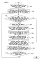
- FIG. 3 shows the flow of threshold candidate value generation processing executed in the threshold value calculation unit 104.
- the errors of two mathematical expression models, among the mathematical expression models managed in the mathematical expression model processing unit 106 are compared and a threshold candidate value for the two mathematical expression models is determined.
- condition quantities calculated by the mathematical expression model processing unit 106 are obtained from the probability model filtering processing unit 103 (step S301). Among the condition quantities thus obtained, no more than a predetermined number of most recently calculated values are stored in correspondence to each mathematical expression model having been used in the calculation.
- a list of a plurality of mathematical expression models that use the condition quantities obtained in step S301, among the plurality of mathematical expression models in the mathematical expression model processing unit 106 is created.
- a state equation or an observation equation is configured with coefficients corresponding to the condition quantities ascertained by referencing the mathematical expression model variable table 111 for each of the mathematical expression models included in the list having been created.
- obtaining a mathematical expression model coefficient corresponding to a condition quantity is to be described as "obtaining a mathematical expression model”.
- Errors are each ascertained in correspondence to one of the mathematical expression models through calculation executed based upon the condition quantity having been obtained (step S302). It is assumed that only mathematical expression models needed when determining threshold candidate values are set in advance in the mathematical expression model variable table 111. It is also assumed that no more than a predetermined number of most recent values indicating the error of each mathematical expression obtained model is stored in the threshold value calculation unit 104 in correspondence to the particular mathematical expression model used in the calculation.
- step S302 A decision is made as to whether or not the list created in step S302 includes a yet-to-be processed condition quantity among the condition quantities obtained in step S301 in correspondence to the mathematical expression models that contain a condition quantity to be used for purposes of comparing errors manifested by mathematical expression models, i.e., in correspondence to the mathematical expression models containing a condition quantity considered as a dominant variable (step S303). It is assumed that condition quantities to be designated as dominant variables are defined in advance in the mathematical expression model variable table 111 stored in the mathematical expression model table 108. As indicated in FIG.
- the names of variables corresponding to the condition quantities processed through each mathematical expression model among the mathematical expression models in the mathematical expression model processing unit 106 and flags each indicating whether or not the corresponding variable is dominant are stored in the mathematical expression model variable table 111. Only the mathematical expression models needed when determining threshold candidate values are set in advance in the mathematical expression model variable table 111. The mathematical expression models are searched sequentially in the order of the numbers assigned thereto in the mathematical expression model table to determine whether or not there is any mathematical expression model containing a selection target condition quantity. Upon detecting a yet-to-be processed condition quantity, the particular condition quantity is selected (step S304).
- step S302 a search for mathematical expression models that use the selected condition quantity as a dominant variable is conducted.
- the list created in step S302 is searched sequentially starting from the first entry, and a pair of mathematical expression models that use the same condition quantity as a dominant variable thereof is selected (step S305) by spotting a first yet-to-be processed mathematical expression model and then looking for a next mathematical expression model using the same condition quantity as a dominant variable.
- step S305 Upon finding a pair of such mathematical expression models, the numbers indicating the most recently checked positions in the mathematical expression model variable table and the mathematical expression model table are temporarily saved before the operation proceeds to execute the processing in steps S306 and S307.
- the curve 201 and the curve 202 in FIG. 2 are determined for the pair of error-comparison target mathematical expression models, i.e., for the two mathematical expression models, in steps S306 and S307.
- the curve 201 and the curve 202 can be determined by setting the error values having been ascertained in step S302 as the errors occurring in relation to the change in the condition quantity selected in step S304.
- the intersecting point A 203 at which the curves, determined through steps S306 and S307 based upon the calculated or estimated errors, intersect each other is calculated and then the value representing the condition quantity at the intersecting point A203 is calculated (step S308).
- the condition quantity value thus calculated is either output as a threshold candidate value to the threshold value determining unit 105 or is buffered in an output standby state (step S309).
- step S310 the list of mathematical expression models created in step S302 is sequentially searched starting with the most recently searched position for mathematical expression models that use the selected condition quantity as a dominant variable thereof.
- the first yet-to-be processed mathematical expression model that is spotted is paired with the next mathematical expression model that uses the same condition quantity as a dominant variable thereof.
- a decision is made as to whether or not the processing in steps S306 through S309 has been completed for all pairs of mathematical expression models sharing the dominant condition quantity. If the calculation for all the pairs of mathematical expression models has been completed ("yes" in step S310), i.e., if all the pairs of mathematical expression models that use the condition quantity selected in step S304 as a dominant variable thereof have been processed, the operation returns to step S303.
- step S309 If there are any data buffered in the output standby state in step S309, the data may be output to the threshold value determining unit 105 at this time. If, on the other hand, the calculation for all the mathematical expression model pairs has not yet been completed, there may still be mathematical expression models to be selected and, accordingly, the operation returns to step S305 to execute the calculation described above again ("no" in step S310).
- step S303 If it is decided in step S303 that there is no more yet-to-be processed condition quantity among the condition quantities used as dominant variables in the mathematical expression models in the list created in step S302 ("no" in step S303), the threshold candidate value generation processing by the threshold value calculation unit 104 ends.
- the threshold value determining unit 105 determines threshold values for various condition quantities based upon threshold candidate values input from the threshold value calculation unit 104. The threshold values thus determined are output to the mathematical expression model table 108.
- the threshold value determining unit 105 has a storage area (not shown) in which the threshold candidate values provided by the threshold value calculation unit 104 are stored.
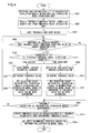
- FIG. 4 presents a flowchart of threshold value determination processing executed when determining threshold values for the individual condition quantities based upon the threshold candidate values having been input from the threshold value calculation unit 104.
- a plurality of mathematical expression models in the mathematical expression model processing unit 106 are obtained from the mathematical expression model variable table 111 in the mathematical expression model table 108 (step S401).
- the threshold candidate values output from the threshold value calculation unit 104 are obtained (step S402) and the threshold candidate values acquired at this time are saved into the area where all the threshold candidate values to date are saved (step S403). If a memory capacity upper limit is set for the area used to save the threshold candidate values, representative values, e.g., average values, may be saved instead of all the previous threshold candidate values.
- step S404 the condition quantity corresponding to a given threshold candidate is selected and a decision is made as to whether or not there is any mathematical expression model, the error of which will be affected by the selected threshold candidate condition quantity. If there is any mathematical expression model, the error of which will fluctuate as the threshold candidate condition quantity fluctuates, the mathematical expression model is assigned to a specific type of processing in step S405 depending upon the characteristics of the threshold candidate condition quantity, i.e., whether the threshold candidate is a time-variant threshold candidate (a condition quantity that fluctuates over time) or a threshold candidate that is time-invariant (a condition quantity that should not fluctuate over time).
- Each condition quantity is categorized either as time-variant or time-invariant in the mathematical expression model table 108, as described in detail later, and thus, the decision as to whether or not the threshold candidate condition quantity is time-variant or time-invariant can be made by referencing the mathematical expression model table 108.
- the operation shifts into step S406, in which a gain is set for a sequential learning method incorporating the previous threshold candidate values, e.g., the Kalman filter method or the method of least squares, so as to be able to closely track fluctuations of the threshold value occurring over time.
- step S407 the value ultimately output by tracking the threshold value through the sequential learning method in step S406 is designated as the threshold value.
- step S408 a mathematical expression model, the error of which will decrease when the condition quantity is greater than the threshold value determined in step S407, and a mathematical expression model, the error of which will decrease when the condition quantity is less than the threshold value determined in step S407, are selected, and the numbers representing the selected mathematical expression models are each set as a target element in a relevant row or column in the mathematical expression model table 108.
- a mathematical expression model the error of which will decrease when the condition quantity is greater than the threshold value determined in step S407
- a mathematical expression model the error of which will decrease when the condition quantity is less than the threshold value determined in step S407
- the error of mathematical expression model 2 will be smaller when the value representing the condition quantity for which the threshold value is set is less than the value B and, accordingly, "2" will be set as an element in the mathematical expression model table, whereas the error of mathematical expression model 1 will be smaller when the value representing the condition quantity for which the threshold value is set, is greater than the value B and, accordingly, "1" will be set as an element in the mathematical expression model table.
- step S409 the operation shifts into step S409, in which a threshold value is determined by taking the average of threshold candidate values or by adopting a clustering method whereby the threshold candidate values to date are divided into two groups, such as the support vector machine method described by Christopher M. Bishop in his "Pattern Recognition and Machine Learning Volume 2", published by Springer Japan, on July 1, 2008, ISBN: 9784431100317 .
- step S410 the value finally output through the processing in step S409 is designated as the threshold value.
- step S411 a mathematical expression model, the error of which will decrease when the condition quantity is greater than the threshold value determined in step S410, and a mathematical expression model, the error of which will decrease when the condition quantity is less than the threshold value determined in step S410, are selected and the numbers representing the selected mathematical expression models are each set as a target element in a relevant row or column in the mathematical expression model table 108.
- step S412 it is verified in step S412 that the threshold values have been determined for all the mathematical expression models through the processing in step S407 or step S410, since the mathematical expression models are each allowed to include a plurality of threshold values (condition quantities) and thus it will not be enough to determine a single threshold value (condition quantity) for a given mathematical expression model. If the threshold values for all the mathematical expression models have not been determined, i.e., if there is a method mathematical expression model for which all the necessary threshold values have not been determined, the operation returns to step S404, to further determine a threshold value.
- step S413 the operation proceeds to step S413 to update the threshold values by deleting the previously designated threshold values and replacing them with the new values calculated through step S407 or step S410.
- the newly designated threshold values are set in the mathematical expression model table 108 in step S414.
- FIG. 9 shows the structure of the mathematical expression model table 108.
- mathematical expression model condition quantities that are crucial factors in determining the extents of error are listed along the vertical direction. These condition quantities are time-variant condition quantities calculated by the probability model filtering processing unit 103.
- the mathematical expression models needed to determine the extents of error will be used in, for instance, an observation equation if the probability model filter processing unit 103 uses a Kalman filter.
- condition quantities indicating the internal conditions in the probability model are entered along the horizontal direction. These are primarily condition quantities calculated based upon the condition quantities calculated by the probability model filtering processing unit 103 and are time-invariant condition quantities.
- a condition quantity included in the vertical list used for mathematical expression model categorization may be also included among the condition quantities listed along the horizontal direction as long as it indicates an internal condition in the probability model by regarding that its fluctuation occurring over time is insignificant.
- the time-invariant condition quantities calculated by the probability model filtering processing unit 103 may include, for instance, an error in a sensor mounting angle. Such a condition quantity will be one of the condition quantities listed along the horizontal direction, and in correspondence to this condition quantity, two states, i.e., learning complete and learning incomplete, will exist. A decision as to whether or not the learning process has been completed will be made through calculation executed separately from the filtering processing in the probability model filtering processing unit 103.
- the extent to which the sensor mounting angle error fluctuates i.e., the stage to which the learning process has advanced, can be expressed as a numerical value by dividing a predetermined variance value by a variance value of the results of error calculation executed to determine the sensor mounting angle error occurring within a specific length of time.
- This numerical value is referred to as a learning level, and a decision as to whether or not the learning process has been completed, is made by using a specific value designated as a threshold value.
- condition quantities indicating internal states further include a gyro sensor bias learning level, a scale factor learning level and a steering angle characteristics learning level. Once the learning level reaches or exceeds 1, the learning process is theoretically considered to have been completed.
- Models representing an optimal combination of the conditions corresponding to the condition quantities selected from the lists running along the vertical axis and the horizontal axis are set in the mathematical expression model table 108. These optimal models are the mathematical expression models selected in step S408 or step S411.
- the mathematical expression model processing unit 106 may hold a plurality of mathematical expression models that are not mutually exclusive. For this reason, a plurality of mathematical expression models may be set in correspondence to the conditions selected from the list running along the vertical direction and the horizontal direction within the mathematical expression model table 108.
- the threshold values having been saved in step S413 are each set as a threshold value along the vertical axis or the horizontal axis in step S414. Assuming that the threshold values set in step S414 are "speed 10 km/h" and “sensor mounting angle learning level 0.1 ", the low-speed traveling state and the high-speed traveling state indicated along the horizontal axis will be respectively less than 10 km/h and equal to or above 10 km/h. Likewise, if the sensor mounting angle learning level is equal to or less than 0.1, “learning incomplete” will be set and if the sensor mounting angle learning level is greater than 0.1, “learning complete” will be set along the horizontal direction.
- the mathematical expression model selection unit 107 selects a plurality of mathematical expression models best suited for the current vehicle conditions based upon the mathematical expression model table 108 created by the threshold value determining unit 105.
- FIG. 6 presents a flowchart of the processing executed by the mathematical expression model selection unit 107 to select a plurality of optimal models among the plurality of mathematical expression models in the mathematical expression model processing unit 106.
- the mathematical expression model table 108 is read in step S601.
- the condition quantities indicating the vehicle behavior, attitude and conditions, having been calculated in the most recent past by the mathematical expression model processing unit 106 are read (step S602).
- step S603 a decision is made as to whether each of the condition quantities having been read belongs to the vertical threshold value list or the horizontal threshold value list set in the mathematical expression model table 108 and a row and a column along which conditions matching the values indicating the vehicle conditions (condition quantities) calculated in correspondence to the vertical axis and the horizontal axis are listed are selected from the mathematical expression model table 108 (step S603). A plurality of rows and a plurality of columns may be selected in this step. In step S604, the optimal mathematical expression models for the corresponding conditions, set in the selected row and column, are read.
- step S605 a verification is executed to check whether or not the mathematical expression models selected in step S604 include any mathematical expression model that has been selected more than once, and if there is a mathematical expression model that has been selected multiple times, the operation shifts into step S606 to first clear the duplicate mathematical expression model and then set the selected mathematical expression models as calculation processing targets to undergo the calculation processing in the mathematical expression model processing unit 106. In other words, it is ensured that a given equation will never be processed multiple times by the mathematical expression model processing unit 106. If it is decided in step S605 that no mathematical expression model has been selected multiple times, the operation shifts into step S607 to set all the mathematical expression models having been selected as processing targets for the mathematical expression model processing unit 106.
- the mathematical expression model processing unit 106 calculates the position and other condition quantities by using the mathematical expression models having been selected by the mathematical expression model selection unit 107 alone. Assuming that the mathematical expression model processing unit 106 manages a total of N mathematical expression models, the mathematical expression model selection unit 107 will select n mathematical expression models among the N mathematical expression models (n is a value equal to or smaller than N). In the mathematical expression model processing unit 106, a probability model state equation or a probability model observation equation corresponding to the n mathematical expression models having been selected by the mathematical expression model selection unit 107 is configured and the position and other condition quantities are calculated by using a probability model filter such as a Kalman filter.
- a probability model filter such as a Kalman filter.
- a predetermined number of values indicating the position and the other condition quantities, are calculated at this time, and this predetermined number is selected irrespective of the number of mathematical expression models selected by the mathematical expression model selection unit 107.
- the probability model filter calculation executed based upon mathematical expressions with lesser extents of error selected as described above assures better accuracy in the condition quantity estimation than that achieved by using all the mathematical expression models, some of which are bound to include information with significant errors, for condition quantity estimation.
- the mathematical expression models may be set in the mathematical expression model processing unit 106 as described below.
- Mathematical expression model 1 is expressed as in (expression 1)
- mathematical expression model 2 is expressed as in (expression 2)
- mathematical expression model 3 is expressed as in (expression 3) below.
- C i represents an observation value corresponding to mathematical expression model i
- (x, y, z) represents all the condition quantities output from the probability model filtering processing unit 103
- a i1 to A i3 each represent a coefficient of one of the condition quantities in mathematical expression model i.
- observation equation can be expressed as in (expression 4) below provided that all the mathematical expression models, with no model among them having been selected multiple times, are set in step S607.
- C Ax C 1 C 2
- C 3 A 11 A 12 A 13 A 21 A 22 A 23 A 13 A 32
- the coefficients set in correspondence to the condition quantities (x, y, z) used in the individual mathematical expression models are read from the mathematical expression model variable table 111 and set as elements (All to A 33 ) of an observation matrix A. It is assumed that if no coefficient is set in the mathematical expression model variable table 111 for a given condition quantity, 0 will be set for that element. In the actual program, various elements (A 11 to A 33 ) of the observation matrix A, in which the coefficients of the condition quantities corresponding to the selected mathematical expression models are grouped together, will be set in conjunction with an "if' statement for use in the Kalman filter.
- this positioning device is adopted in a car navigation system equipped with a steering angle sensor and a gyro sensor, that a speed-based Ackerman model and a speed-based dead-reckoning model are used as the mathematical expression models and that an extended Kalman filter is used in the probability model filter processing unit 103, the operation of the positioning device is described in specific detail.
- the angular speedy is expressed as in (expression 6) below with the vehicle speed v, the actual steering angle ⁇ and the distance 1 between the front axle and the rear axle.
- ⁇ ⁇ ⁇ ⁇ / 1
- the angular speed is calculated by using an output value ⁇ gyro provided by the gyro sensor, and accordingly, the angular speed ⁇ is calculated as expressed in (expression 7) below with a gyro sensor sensitivity coefficient S and a bias.
- ⁇ S ⁇ ⁇ gyro + bias
- the position and the azimuth (x, y, ⁇ ) of the vehicle within the two-dimensional plane can be calculated as expressed in the following expression (expression 8) based upon the speed v in correspondence to a given time point t and a unit time ⁇ t.
- x ⁇ t + 1 y ⁇ t + 1 ⁇ ⁇ t + 1 x t y t ⁇ t + cos ⁇ t sin ⁇ t ⁇ t ⁇ v ⁇ t
- the speed v can be designated as a condition quantity to be used as a dominant variable in conjunction with these two mathematical expression models. While the Ackerman model is valid in a low-speed range as explained earlier, the maximum speed level at which the validity of the model holds varies depending upon the particulars of the vehicle and the current road characteristics.
- the device determines a speed threshold value, i.e., the speed limit at which the validity of the Ackerman model is sustained, through the method described earlier.
- the equation in (expression 8) constitutes part of the state equation in the extended Kalman filter, whereas the equation in (expression 6) and (expression 7) constitutes part of the observation equation in the extended Kalman filter.
- the probability model filtering processing unit 103 outputs the following condition quantities; the position (two-dimensional), the azimuth, the speed and the angular speed.
- the differences between the angular speed value calculated by the probability model filtering processing unit 103 by using the extended Kalman filter and the observation value calculated by using the Ackerman model as expressed in (expression 6) and between the angular speed value calculated by using the extended Kalman filter and the observation value calculated by using the dead-reckoning model as expressed in (expression 7) are output to the threshold value calculation unit 104 respectively as an Ackerman model error and a dead-reckoning model error.
- the threshold value calculation unit 104 determines through approximation a curve representing the relation of the value indicating the error of each mathematical expression model to the vehicle speed v by using the speed v(t) and the error value e(t) corresponding to the particular mathematical expression model, having been input thereto from the probability model filtering processing unit 103 up to the time point t.
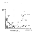
- a graph such as that shown in FIG. 7 , with the error indicated along the vertical axis and the vehicle speed v indicated along the horizontal axis, is generated.
- a curve 701 represents the dead-reckoning model error and a curve 702 represents the Ackerman model error.
- the graph is created by determining through approximation curves respectively connecting points 703, indicated by X marks, representing the speed-related error of the dead-reckoning model, plotted up to the time point t and connecting point 704, indicated by O marks representing the speed-related error of the Ackerman model, plotted up to the time point t.
- the speed value assumed at a point 705 at which the curve 701 and the curve 702 intersect each other is output as a threshold candidate value v th to the threshold value determining unit 105. Since the threshold candidate value v th thus calculated has time-variant characteristics which are affected by factors such as the extent to which the tires are worn, changes in the road characteristics and the like, change-tracking processing executed through sequential learning is selected in step S405.
- the change having occurred in the threshold candidate value up to the time point t may be plotted as points 801 indicated by O marks in FIG. 8 .
- the change in the threshold value v th (t) can be expressed as threshold value change characteristics with the following two expressions (expression 9) and (expression 10) with a time constant ⁇ .
- v th in the right side of (expression 10) is the current threshold candidate value input from the threshold value calculation unit 104.
- a threshold value v th (t) 802 can be determined for the current session.
- a curve 803 in FIG. 8 indicates the value constantly and sequentially determined as the threshold.
- the threshold value v th (t) 802 thus determined is set in the mathematical expression model table 108.
- the mathematical expression model table 108 in FIG. 9 includes the Ackerman model assigned with mathematical expression model ID No. 1 and the dead-reckoning model assigned with mathematical expression model ID No. 2.
- the state in which the speed is lower than the threshold value v th (t) 802 can be defined as a low-speed traveling state, whereas the state in which the speed is higher than the threshold value v th (t) 802 can be defined as a high-speed traveling state.
- the values "1", “2"... in the figure each indicate the ID number used to identify the corresponding mathematical expression model in the mathematical expression model processing unit 106, whereas the symbol "/" indicates that either mathematical expression model is applicable.
- the mathematical expression model selection unit 107 selects applicable rows and columns in the mathematical expression model table 108, corresponding to the condition quantities having been calculated by the probability model filtering processing unit 103 in the immediately preceding session, by referencing the mathematical expression model table 108.
- the vehicle is known to have been in the low-speed traveling state during the immediately preceding session, and thus, the row enclosed in a solid-line frame 902 in FIG. 9 is the selected row.
- the table elements enclosed in both a dotted-line frame 901 and the solid-line frame 902 each indicate a mathematical expression model that should be selected at this time and, since all the elements are assigned with ID No. 1, the Ackerman model, i.e., mathematical expression model 1, alone is selected. Consequently, an observation equation constituted with the Ackerman model alone is used as the observation equation in the extended Kalman filter at the probability model filtering processing unit 103 at a time point t + 1.
- the mathematical expression model processing unit 106 executes calculation by using different mathematical expression models depending upon whether the steering angle sensor or the gyro sensor is used. Whenever the mathematical expression model selection unit 107 switches over from the Ackerman model to the dead-reckoning model or vice versa to select the alternative mathematical expression model to be used in the calculation executed by the mathematical expression model processing unit 106, the corresponding sensor is selected simultaneously as the mathematical expression model switchover occurs. Subsequently, the mathematical expression model processing unit 106 executes calculation by using the mathematical expression model having been selected through the switchover.
- the positioning device Operation of the positioning device is next described in reference to an example in which the positioning device is adopted in a car navigation system equipped with GPS and a gyro sensor and mathematical expression models are switched so as to select a sensor fusion model when the GPS is used and select a dead-reckoning model when no GPS signals are received or the GPS is not used.
- the sensor fusion model enables estimation of the most likely position by fusing, as described above, via an extended Kalman filter, the GPS position and the dead-reckoning position provided by an internal sensor such as a gyro sensor.
- An internal sensor model outputs the dead-reckoning position detected by an internal sensor such as a gyro sensor as described above.
- the state equation in the extended Kalman filter used in the embodiment is assumed to be identical to that expressed in (expression 8).
- the sensor fusion model expressed in (expression 12) and the internal sensor model expressed in (expression 13) are both mathematical expression models in the observation equation.
- the sensor fusion model is valid when the GPS is used.
- the positioning device determines a threshold value constituting a criterion for validating the sensor fusion model through the method described earlier by designating a distance limit for the distance between the currently estimated position and the GPS position as a condition quantity to be used as a dominant variable in the processing.
- the probability model filtering processing unit 103 which uses the extended Kalman filter, is first examined.
- the equation in (expression 8) constitutes part of the state equation in the extended Kalman filter
- the equations in (expression 12) and (expression 13) constitute part of the observation equation in the extended Kalman filter.
- the probability model filtering processing unit 103 outputs the following condition quantities; the position (two-dimensional) and the azimuth.
- (x(t), y(t), ⁇ (t)) represents the condition quantities calculated at the given time point t by the probability model filtering processing unit 103 with the extended Kalman filter by using the internal sensor model expressed in (expression 13). Based upon these condition quantities having been calculated, the distance L between the currently estimated position and the GPS position, to be used as a criterion for switching over between the sensor fusion model and the internal sensor model, is calculated as expressed in (expression 14) below.
- L x t - x gps t 2 + y t - y gps t 2
- the distance L calculated as expressed in (expression 14) is then output to the threshold value calculation unit 104.
- the differences between the estimated position calculated by the probability model filtering processing unit 103 by using the extended Kalman filter and the observation value calculated by using the sensor fusion model as expressed in (expression 12) and between the estimated position value calculated by using the extended Kalman filter and the observation value calculated by using the internal sensor model as expressed in (expression 13) are output to the threshold value calculation unit 104 respectively as a sensor fusion model error and an internal sensor model error.
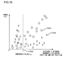
- the threshold value calculation unit 104 is able to generate a distribution graph such as that shown in FIG. 10 , by using the distance L(t) between the currently estimated position and the GPS position and the error e(t) of the respective model having been input from the probability model filtering processing unit 103 up to the time point t.
- the error is indicated along the vertical axis
- the distance L between the currently estimated position and the GPS position is indicated along the horizontal axis.
- Points 1001 indicated by O marks in FIG. 10 each represent the sensor fusion model error relative to the position estimated by the probability model filtering processing unit 103
- points 1002 indicated by X marks in FIG. 10 each represent the internal sensor model error relative to the position estimated by the probability model filtering processing unit 103.
- These points are divided into two groups with a given value L th set as a cutoff point by using the support vector machine mentioned earlier. This value L th is output to the threshold value determining unit 105 where it is saved as a threshold candidate value L th .
- the threshold determining unit 105 designates the average of the threshold candidate value corresponding to the time point t and the threshold candidate values having been calculated up to the time point t as a current threshold value L th (t).
- the threshold value L th (t) thus determined is set in the mathematical expression model table 108.
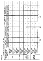
- the mathematical expression model table 108 in FIG. 11 includes the sensor fusion model assigned with mathematical expression model ID No. 5 and the internal sensor model assigned with mathematical expression model ID No. 6.
- this mathematical expression model expression table 108 specific settings, i.e., a GPS reception setting selected so as to fuse the GPS position when the distance between the currently estimated position and the GPS position is less than the threshold value L th (t) and a GPS non-reception setting selected so as to disregard the GPS position when the distance greater than the threshold value is output, are defined.
- the mathematical expression model selection unit 107 selects applicable rows and columns in the mathematical expression model table 108, corresponding to the condition quantities having been calculated by the probability model filtering processing unit 103 in the immediately preceding session, by referencing the mathematical expression model table 108.
- the condition quantities having been output from the probability model filtering processing unit 103 through the immediately preceding session are the gyro bias, the gyro scale factor, the sensor mounting angle and the steering angle characteristics and that the respective learning levels have been calculated as "learning complete” for the gyro bias learning level, "learning complete” for the gyro scale factor learning level, “learning incomplete” for the sensor mounting angle learning level and “learning complete” for the steering angle characteristics learning level, the columns enclosed in dotted-line frames 1101 in FIG.
- the table elements enclosed in both a dotted-line frame 1101 and the solid-line frame 1102 each indicate a mathematical expression model that should be selected at this time, and since all the elements are assigned with ID No. 5, the sensor fusion model, i.e., mathematical expression model 5, alone is selected. Consequently, (expression 12) alone is used as the observation equation in the extended Kalman filter at the probability model filtering processing unit 103 at a time point t + 1.
- the operational procedure of the positioning device is described in reference to an example in which the positioning device is adopted in a car navigation system equipped with digital map information, a GPS, a gyro sensor and an attitude sensor such as an acceleration sensor and capable of locating the subject vehicle position on the digital map through map matching, and mathematical expression models are switched to select a sensor fusion model (hereafter to be referred to as a link fusion model) to be used in conjunction with link information included in the digital map data or a sensor fusion model (hereafter referred to as an INS model) when the link information in the digital map data is not utilized.
- a sensor fusion model hereafter to be referred to as a link fusion model
- an INS model sensor fusion model
- the digital map data are managed in units of meshes ranging over a predetermined area.
- the meshes in the map each include points (nodes) with coordinates so as to express shapes of roads.
- a specific number is assigned to each node (node point number) for identification purposes.
- the X coordinate of a given node indicates the longitudinal reading of the node, whereas the Y coordinate of the node indicates the latitudinal reading of the node.
- the distance between two successive nodes is referred to as a node link length
- the width of a given road is referred to as a node link width
- both the node link length and the node link width are indicated in units of meters.
- the link fusion model which is a mathematical expression model that uses links in the digital map data in the Kalman filter observation equation as explained earlier, can be expressed as in (expression 16) below with the slope ⁇ of a link, a link intercept c, the distance r from the link and the slope ⁇ to the link.
- 0 0 x t ⁇ sin ⁇ - y t ⁇ cos ⁇ - c - r ⁇ - ⁇ - ⁇
- the link fusion model assumes that the vehicle is currently present on a link so that, if there is an error in the map information, the position output from the probability model filtering processing unit 103, too, may also contain a significant error.
- an angular speed value from the gyro sensor and an acceleration value from the acceleration sensor are obtained and converted respectively to an azimuth and a speed by being integrated. While the angular speed is calculated as expressed in (expression 7), the acceleration ACC may be calculated as expressed in (expression 17) below.
- ACC S acc ⁇ G Gsns - g ⁇ sin ⁇ + bias
- S acc represents the sensitivity coefficient of the accelerator sensor
- G Gsns represents the raw output value from the acceleration sensor
- g represents the gravitational acceleration
- ⁇ represents the sensor mounting angle
- the link fusion model which is bound to manifest a significant error if there is an error in the map information, as described earlier, should not be used with erroneous map information. Accordingly, on the premise that "map information is used when the distance between the GPS position and the link is small" by assuming that a position that can be considered roughly correct is output as the GPS position, a time-invariant threshold value, under normal circumstances, is bound to exist between the link fusion model and the INS model. There may be a situation in which the GPS position itself has an error and thus, better accuracy can be assured if the GPS position is not used, as has been explained in reference to the second embodiment.
- the distance between the GPS position and the link is defined as a map error quantity, i.e., a condition quantity, is used as a dominant variable.
- a threshold value to be used as a criterion for validating the link fusion model is determined for the map error quantity and a threshold value is further determined by taking into consideration the GPS reception position, as in the second embodiment.
- the probability model filtering processing unit 103 that uses the extended Kalman filter is first examined.
- the equation in (expression 8) constitutes part of the state equation in the extended Kalman filter
- the equation in (expression 16) and (expression 7) and (expression 17) constitute part of the observation equation in the extended Kalman filter.
- the probability model filtering processing unit 103 outputs condition quantities; the position (two-dimensional) and the azimuth.
- (x(t), y(t), ⁇ (t)) represents the condition quantities calculated at the given time point t by the probability model filtering processing unit 103 with the extended Kalman filter by using the internal sensor model expressed in (expression 13).
- a link equation such as that in (expression 18) can be written based upon the X coordinates and the Y coordinates of the nodes at the two ends of the link matched through the map matching operation executed by the subject vehicle position estimation device 102, as described earlier.
- the distance r GPs between the currently estimated position (at the time point t) and the link, needed for switchover between the link fusion model and the INS model, which is a distance between a point (the GPS position) and a straight line (the link equation in (expression 18)), can be calculated as follows.
- r GPS x gps t ⁇ sin ⁇ - y gps t ⁇ cos ⁇ - c
- the distance r GPs calculated as expressed in (expression 19) is then output to the threshold value calculation unit 104.
- the differences between the estimated position value calculated by the probability model filtering processing unit 103 by using the extended Kalman filter and the observation value calculated by using the link fusion model as expressed in (expression 16) and between the estimated position value calculated by using the extended Kalman filter and the observation value calculated by using the INS model as expressed in (expression 7) and (expression 17) are output to the threshold value calculation unit 104 respectively as a link fusion model error and an INS model error.
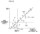
- the threshold value calculation unit 104 is able to generate a distribution graph such as that shown in FIG. 12 , by using the distance r GPS (t) from the currently estimated position to the link position and the error e(t) of each model having been input from the probability model filtering processing unit 103 up to the time point t.
- the error is indicated along the vertical axis
- the distance r GPs between the currently estimated position (GPS position) and the link position is indicated along the horizontal axis.
- Points 1201 indicated by O marks in FIG. 12 each represent the error, i.e., the distance between the GPS position and the link.
- the points are linearly approximated through the method of least squares to obtain a straight line 1202.
- a threshold value L th under the GPS reception setting is calculated in much the same way as that described in reference to the second embodiment, and a value 1203 representing the corresponding INS error is then determined.
- the error i.e., the distance between the GPS position and the link
- the GPS position can be considered to be roughly correct and, accordingly, a distance r th 1204 between the GPS position and the link, measured when the value 1203 is assumed in the straight line 1202, is selected as the threshold candidate value in this situation.
- the distance r th is output to the threshold determining unit 105 and is saved in the threshold value determining unit 105.
- the threshold value determining unit 105 designates the average of the threshold candidate value corresponding to the time point t and the threshold candidate values having been calculated up to the time point t as a current threshold value r th (t).
- the threshold value r th (t) thus determined is set in the mathematical expression model table 108.
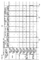
- the mathematical expression model table 108 in FIG. 13 includes the link fusion model assigned with mathematical expression model ID No. 7 and the INS model assigned with mathematical expression model ID No. 5.
- the distance between the GPS position and the link assuming an output value smaller than the threshold value r th (t) is defined as a "small map error" and the distance between the GPS position and the link assuming an output value greater than the threshold value r th (t) is defined as a "large map error”.
- the mathematical expression model selection unit 107 selects applicable rows and columns in the mathematical expression model table 108, corresponding to the condition quantities having been calculated by the probability model filtering processing unit 103 in the immediately preceding session, by referencing the mathematical expression model table 108.
- the condition quantities having been output from the probability model filtering processing unit 103 through the immediately preceding session are the gyro bias, the gyro scale factor, the sensor mounting angle and the steering angle characteristics and that the respective learning levels have been calculated as "learning complete” for the gyro bias learning level, "learning complete” for the gyro scale factor learning level, “learning incomplete” for the sensor mounting angle learning level and “learning complete” for the steering angle characteristics learning level, the columns enclosed in dotted-line frames 1301 in FIG.
- the map error can be determined to be small and thus, the row enclosed within a solid-line frame 1303 in FIG. 13 are selected. Accordingly, the table elements enclosed in both a dotted-line frame 1301 and a dashed-line frame 1302 or the solid-line frame 1303 each indicate a mathematical expression model that should be selected at this time. Since mathematical expression model No. 5 and mathematical expression model No. 7 are both indicated by the table elements, both the INS model and the link fusion model are selected. Accordingly, at a time point t+ 1, the probability model filtering processing unit 103 uses (expressions 7), (expression 16) and (expression 17) in the observation equation in the extended Kalman filter.
Claims (5)
- Dispositif d'estimation de position (102), comprenant :une unité de traitement de modèle d'expression mathématique (106) qui obtient une information d'attitude et une information de positionnement indiquant une attitude et une position mesurée d'un objet mobile à partir de capteurs et qui calcule une position de l'objet mobile, une quantité de condition indiquant une condition de mouvement de l'objet mobile et une erreur dans la quantité de condition via un traitement de filtrage exécuté en utilisant un modèle de probabilité basé sur l'information d'attitude et sur l'information de positionnement qui ont été obtenues et un modèle d'expression mathématique spécifique parmi une pluralité de modèles d'expression mathématique exprimant le comportement de l'objet mobile, qui sont acquises à l'avance,caractérisé par :une unité de calcul de seuil (104) qui calcule une valeur candidate de seuil pour une valeur seuil à utiliser à titre de critère lorsqu'on sélectionne le modèle d'expression mathématique spécifique, en utilisant l'erreur qui a été calculée par l'unité de traitement de modèle d'expression mathématique ;une unité de détermination de valeur seuil (105) qui détermine la valeur seuil en se basant sur la valeur candidate de seuil ; etune unité de sélection de modèle d'expression mathématique (107) qui sélectionne le modèle d'expression mathématique spécifique en se basant sur la valeur seuil déterminée par l'unité de détermination de valeur seuil.
- Dispositif d'estimation de position (102) selon la revendication 1, dans lequel :des restrictions, imposées à l'égard d'une plage valide dans laquelle chacun de la pluralité de modèles d'expression mathématique exprimant le comportement est applicable aux comportements, sont définies en se basant sur l'information qui peut être recueillie par observation faite depuis l'extérieur ou en se basant sur la position, sur la quantité de condition et sur l'erreur calculées par l'unité de traitement de modèle d'expression mathématique ;l'unité de détermination de valeur seuil (105) détermine la valeur seuil en se basant sur des valeurs représentant des étendues de l'erreur calculée chacune en correspondance de l'un de la pluralité de modèles d'expression mathématique ; etl'unité de sélection de modèle d'expression mathématique sélectionne le modèle d'expression mathématique spécifique en correspondance des restrictions.
- Dispositif d'estimation de position selon la revendication 2, comprenant en outre :une base de données dans laquelle les restrictions et la valeur seuil sont stockées.
- Procédé d'estimation de position, comprenant les étapes consistant à :obtenir une information d'attitude et une information de positionnement indiquant une attitude et une position mesurée d'un objet mobile à partir de capteurs ;calculer une position de l'objet mobile, une quantité de condition indiquant une condition de mouvement de l'objet mobile et une erreur dans la quantité de condition par traitement de filtrage exécuté en utilisant un modèle de probabilité basé sur l'information d'attitude et sur l'information de positionnement qui ont été obtenues et un modèle d'expression mathématique spécifique parmi une pluralité de modèles d'expression mathématique exprimant le comportement de l'objet mobile, qui sont acquises à l'avance, caractérisé par les étapes consistant à :calculer une valeur candidate de seuil pour une valeur seuil à utiliser à titre de critère lorsqu'on sélectionne le modèle d'expression mathématique spécifique, en utilisant l'erreur qui a été calculée ;déterminer la valeur seuil en se basant sur la valeur candidate ; etsélectionner le modèle d'expression mathématique spécifique en se basant sur la valeur seuil qui a été déterminée.
- Procédé d'estimation de position selon la revendication 4, dans lequel :des restrictions, imposées à l'égard d'une plage valide dans laquelle chacun de la pluralité de modèles d'expression mathématique exprimant le comportement est applicable au comportement, sont définies en se basant sur l'information qui peut être recueillie par observation faite depuis l'extérieur ou en se basant sur la position, la quantité de condition et l'erreur qui ont été calculées ;la valeur seuil est déterminée en se basant sur des valeurs représentant des étendues de l'erreur calculées chacune en correspondance de l'un de la pluralité de modèles d'expression mathématique ; etle modèle d'expression mathématique spécifique est sélectionné en correspondance des restrictions.
Applications Claiming Priority (1)
| Application Number | Priority Date | Filing Date | Title |
|---|---|---|---|
| JP2010038104A JP5017392B2 (ja) | 2010-02-24 | 2010-02-24 | 位置推定装置および位置推定方法 |
Publications (3)
| Publication Number | Publication Date |
|---|---|
| EP2363732A2 EP2363732A2 (fr) | 2011-09-07 |
| EP2363732A3 EP2363732A3 (fr) | 2014-01-22 |
| EP2363732B1 true EP2363732B1 (fr) | 2015-06-10 |
Family
ID=44147646
Family Applications (1)
| Application Number | Title | Priority Date | Filing Date |
|---|---|---|---|
| EP11154878.0A Active EP2363732B1 (fr) | 2010-02-24 | 2011-02-17 | Dispositif d'évaluation de position et procédé d'évaluation de position |
Country Status (4)
| Country | Link |
|---|---|
| US (1) | US9057781B2 (fr) |
| EP (1) | EP2363732B1 (fr) |
| JP (1) | JP5017392B2 (fr) |
| CN (1) | CN102192745B (fr) |
Families Citing this family (40)
| Publication number | Priority date | Publication date | Assignee | Title |
|---|---|---|---|---|
| KR101126808B1 (ko) * | 2010-03-02 | 2012-03-23 | 경북대학교 산학협력단 | 다축 제어 기계의 오차 평가 방법 및 장치 |
| JP5310766B2 (ja) * | 2011-03-28 | 2013-10-09 | ソニー株式会社 | 位置補正装置、位置補正方法、プログラムおよび位置補正システム |
| WO2012167367A1 (fr) * | 2011-06-09 | 2012-12-13 | Trusted Positioning Inc. | Procédé et appareil de positionnement et de navigation en temps réel d'une plate-forme mobile |
| US9167463B2 (en) * | 2011-09-02 | 2015-10-20 | Telcordia Technologies, Inc. | Communication node operable to estimate faults in an ad hoc network and method of performing the same |
| CA2847577A1 (fr) * | 2011-09-19 | 2013-03-28 | Curtin University Of Technology | Procede d'estimation de quantite associee a un systeme de recepteurs |
| EP2574880A3 (fr) * | 2011-09-30 | 2015-05-20 | Maishi Electronic (Shanghai) Ltd. | Procédé, appareil et système avec correction d'erreur pour système de navigation inertielle |
| JP5852920B2 (ja) * | 2012-05-17 | 2016-02-03 | クラリオン株式会社 | ナビゲーション装置 |
| JP5894865B2 (ja) * | 2012-05-29 | 2016-03-30 | クラリオン株式会社 | 車両位置検出装置、及びプログラム |
| CN104019822B (zh) * | 2013-02-28 | 2017-05-24 | 北京四维图新科技股份有限公司 | 一种汽车导航方法、装置及导航终端 |
| WO2015079731A1 (fr) * | 2013-11-29 | 2015-06-04 | クラリオン株式会社 | Dispositif d'apprentissage de facteur de distance, procédé d'apprentissage de facteur de distance et dispositif de calcul de position actuelle |
| JP6299289B2 (ja) * | 2014-03-06 | 2018-03-28 | 株式会社豊田中央研究所 | パラメータ学習装置、運転支援装置、及びプログラム |
| US9529089B1 (en) * | 2014-03-31 | 2016-12-27 | Amazon Technologies, Inc. | Enhancing geocoding accuracy |
| CN104019813B (zh) * | 2014-06-19 | 2017-01-25 | 无锡知谷网络科技有限公司 | 目标即时定位和构建地图的方法与系统 |
| FR3023623B1 (fr) * | 2014-07-09 | 2023-05-05 | Sagem Defense Securite | Procede d'estimation de l'etat d'un systeme mobile et centrale inertielle correspondante. |
| DE102015216890A1 (de) * | 2014-09-24 | 2016-03-24 | Continental Teves Ag & Co. Ohg | Key-Inbetween-Konzept für M2XPro |
| US9746331B1 (en) * | 2014-12-15 | 2017-08-29 | Marvell International Ltd. | Method and apparatus for map matching |
| JP6520203B2 (ja) * | 2015-02-25 | 2019-05-29 | 株式会社デンソー | 搭載角度誤差検出方法および装置、車載レーダ装置 |
| JP6556562B2 (ja) * | 2015-08-28 | 2019-08-07 | 株式会社デンソーテン | 情報処理装置、情報処理方法および情報処理システム |
| JP6380422B2 (ja) | 2016-02-05 | 2018-08-29 | トヨタ自動車株式会社 | 自動運転システム |
| JP6139722B1 (ja) * | 2016-02-19 | 2017-05-31 | ヤフー株式会社 | 推定装置、推定方法及び推定プログラム |
| DE102016002603A1 (de) * | 2016-03-03 | 2017-09-07 | Audi Ag | Verfahren zur Ermittlung und Bereitstellung einer auf eine vorbestimmte Umgebung bezogenen, Umfelddaten enthaltenden Datenbank |
| JP6689659B2 (ja) * | 2016-04-19 | 2020-04-28 | クラリオン株式会社 | 位置推定装置、及び、推定方法 |
| US10838837B2 (en) * | 2016-06-24 | 2020-11-17 | International Business Machines Corporation | Sensor based system state prediction |
| US9965051B2 (en) * | 2016-06-29 | 2018-05-08 | Microsoft Technology Licensing, Llc | Input device tracking |
| US10421452B2 (en) * | 2017-03-06 | 2019-09-24 | GM Global Technology Operations LLC | Soft track maintenance |
| JP6922375B2 (ja) * | 2017-04-20 | 2021-08-18 | 住友電気工業株式会社 | 車載通信システム、車載装置、通信制御方法および通信制御プログラム |
| CN107274721B (zh) * | 2017-06-07 | 2020-03-31 | 北京科技大学 | 一种智能交通系统中多车辆协作定位方法 |
| JP7087794B2 (ja) * | 2018-07-31 | 2022-06-21 | トヨタ自動車株式会社 | 情報処理システム、プログラム、及び制御方法 |
| US10937263B1 (en) | 2018-09-27 | 2021-03-02 | Amazon Technologies, Inc. | Smart credentials for protecting personal information |
| US10832444B2 (en) * | 2019-02-18 | 2020-11-10 | Nec Corporation Of America | System and method for estimating device pose in a space |
| CN113474796A (zh) * | 2019-03-04 | 2021-10-01 | 三菱电机株式会社 | 信息处理装置、信息处理方法以及信息处理程序 |
| US11474530B1 (en) | 2019-08-15 | 2022-10-18 | Amazon Technologies, Inc. | Semantic navigation of autonomous ground vehicles |
| CN112824185B (zh) * | 2019-11-19 | 2022-05-03 | 广州汽车集团股份有限公司 | 一种碰撞预警方法、集成tbox的v2x控制器系统及汽车 |
| JP7409037B2 (ja) * | 2019-11-21 | 2024-01-09 | 株式会社デンソー | 推定装置、推定方法、推定プログラム |
| JP7307003B2 (ja) | 2020-02-04 | 2023-07-11 | 株式会社日立製作所 | 運転モード検出装置、運転モード検出システム及び運転モード検出方法 |
| JP7381719B2 (ja) * | 2020-03-30 | 2023-11-15 | 三菱重工機械システム株式会社 | データ生成装置、データ生成方法、及びプログラム |
| CN111521195B (zh) * | 2020-04-10 | 2022-03-04 | 广州铁路职业技术学院(广州铁路机械学校) | 一种智能机器人 |
| CN113899363B (zh) * | 2021-09-29 | 2022-10-21 | 北京百度网讯科技有限公司 | 车辆的定位方法、装置及自动驾驶车辆 |
| JP2023094745A (ja) * | 2021-12-24 | 2023-07-06 | 日立Astemo株式会社 | 車載演算処理装置、および、演算処理方法 |
| JPWO2023162017A1 (fr) * | 2022-02-22 | 2023-08-31 |
Family Cites Families (40)
| Publication number | Priority date | Publication date | Assignee | Title |
|---|---|---|---|---|
| JPH05333132A (ja) * | 1992-06-03 | 1993-12-17 | Hitachi Ltd | Gps測位方法及び装置 |
| US5499306A (en) * | 1993-03-08 | 1996-03-12 | Nippondenso Co., Ltd. | Position-and-attitude recognition method and apparatus by use of image pickup means |
| JP3246822B2 (ja) * | 1994-02-03 | 2002-01-15 | 株式会社日立製作所 | 移動体のトラッキング装置 |
| JP3412262B2 (ja) * | 1994-06-30 | 2003-06-03 | アイシン精機株式会社 | 車上測位装置 |
| JP3378360B2 (ja) * | 1994-06-30 | 2003-02-17 | 松下電器産業株式会社 | 速度センサ係数算出装置 |
| ZA957639B (en) * | 1994-10-24 | 1996-05-24 | Caterpillar Inc | System and method for precisely determining an operating point for an autonomous vehicle |
| JPH10176932A (ja) * | 1996-10-14 | 1998-06-30 | Yokogawa Denshi Kiki Kk | 慣性航法装置 |
| US6289280B1 (en) * | 1999-12-10 | 2001-09-11 | Qualcomm Incorporated | Method and apparatus for determining an algebraic solution to GPS terrestrial hybrid location system equations |
| JP2002123894A (ja) * | 2000-10-16 | 2002-04-26 | Hitachi Ltd | プローブカー制御方法及び装置並びにプローブカーを用いた交通制御システム |
| US6816799B2 (en) * | 2002-08-05 | 2004-11-09 | Robert Bosch Corporation | Vehicle operating parameter determination system and method |
| CN1278501C (zh) * | 2002-12-06 | 2006-10-04 | 国际商业机器公司 | 移动目标位置数据的压缩方法和压缩设备 |
| EP1500907B1 (fr) | 2003-07-21 | 2014-11-12 | LG Electronics, Inc. | Appareil et procédé pour détecter la position d'un véhicule dans un système de navigation |
| JP4043416B2 (ja) * | 2003-07-30 | 2008-02-06 | オリンパス株式会社 | 安全移動支援装置 |
| US7222007B2 (en) * | 2004-01-07 | 2007-05-22 | Ford Global Technologies, Llc | Attitude sensing system for an automotive vehicle relative to the road |
| DE102004005380A1 (de) * | 2004-02-03 | 2005-09-01 | Isra Vision Systems Ag | Verfahren zur Bestimmung der Lage eines Objekts im Raum |
| US20050197768A1 (en) * | 2004-03-04 | 2005-09-08 | Nokia Corporation | Adjustment of the operation of an application based on a geographically varying parameter value |
| US7451033B2 (en) * | 2005-06-10 | 2008-11-11 | Ford Global Technologies, Llc | Lateral and longitudinal velocity determination for an automotive vehicle |
| US9198728B2 (en) * | 2005-09-30 | 2015-12-01 | Intouch Technologies, Inc. | Multi-camera mobile teleconferencing platform |
| JP4702800B2 (ja) * | 2006-03-23 | 2011-06-15 | アルパイン株式会社 | Gps測位による位置算出装置 |
| JP4148276B2 (ja) * | 2006-05-09 | 2008-09-10 | ソニー株式会社 | 位置推定装置、位置推定方法及びプログラム記録媒体 |
| JP4984659B2 (ja) * | 2006-06-05 | 2012-07-25 | 株式会社豊田中央研究所 | 自車両位置推定装置 |
| JP4124249B2 (ja) * | 2006-07-25 | 2008-07-23 | トヨタ自動車株式会社 | 測位装置、ナビゲーションシステム |
| US7865299B2 (en) * | 2006-09-14 | 2011-01-04 | Toyota Motor Engineering & Manufacturing North America, Inc. | Method and system for predicting a future position of a vehicle using numerical integration |
| WO2008036354A1 (fr) * | 2006-09-19 | 2008-03-27 | Braintech Canada, Inc. | Système et procédé de détermination de la pose d'un objet |
| US20080077325A1 (en) * | 2006-09-25 | 2008-03-27 | Honeywell International Inc. | Systems and methods for a hybrid transition matrix |
| JP2008281552A (ja) * | 2007-04-09 | 2008-11-20 | Seiko Epson Corp | 初回測位出力位置演算決定方法、プログラム、記憶媒体、測位装置及び電子機器 |
| JP4985095B2 (ja) | 2007-05-21 | 2012-07-25 | アイシン・エィ・ダブリュ株式会社 | 安全運転支援装置、安全運転支援方法及びプログラム |
| CN101316439B (zh) * | 2007-05-31 | 2012-06-27 | 株式会社Ntt都科摩 | 服务器装置、移动终端以及定位方式选择方法 |
| JP5270184B2 (ja) * | 2008-02-13 | 2013-08-21 | 古野電気株式会社 | 衛星航法/推測航法統合測位装置 |
| JP5385893B2 (ja) * | 2008-03-11 | 2014-01-08 | パナソニック株式会社 | 位置特定システムおよびセンサ装置 |
| US7800541B2 (en) * | 2008-03-31 | 2010-09-21 | Golba Llc | Methods and systems for determining the location of an electronic device |
| JP5090287B2 (ja) | 2008-08-07 | 2012-12-05 | 株式会社日立製作所 | タービン動翼とその固定構造 |
| US8489317B2 (en) * | 2008-08-29 | 2013-07-16 | Toyota Motor Engineering & Manufacturing North America, Inc. | System and method for stochastically predicting the future states of a vehicle |
| CN101592492B (zh) * | 2009-07-06 | 2011-04-13 | 北京航空航天大学 | 车载导航系统误差协方差阵部分参数自适应调节的方法 |
| US20110021207A1 (en) * | 2009-07-24 | 2011-01-27 | Morgan Edward J | System and Method for Estimating Positioning Error Within a WLAN-Based Positioning System |
| US8386620B2 (en) * | 2009-12-15 | 2013-02-26 | Apple Inc. | Ad hoc networking based on content and location |
| CN102449427A (zh) * | 2010-02-19 | 2012-05-09 | 松下电器产业株式会社 | 物体位置修正装置、物体位置修正方法及物体位置修正程序 |
| JP5114514B2 (ja) * | 2010-02-25 | 2013-01-09 | 株式会社日立製作所 | 位置推定装置 |
| JP5273126B2 (ja) * | 2010-09-15 | 2013-08-28 | カシオ計算機株式会社 | 測位装置、測位方法およびプログラム |
| KR20120080776A (ko) * | 2011-01-10 | 2012-07-18 | 삼성전자주식회사 | 추정 위치의 신뢰도 제공 방법 및 이를 구현하는 이동 단말기 |
-
2010
- 2010-02-24 JP JP2010038104A patent/JP5017392B2/ja active Active
-
2011
- 2011-02-17 EP EP11154878.0A patent/EP2363732B1/fr active Active
- 2011-02-17 CN CN201110042095.XA patent/CN102192745B/zh active Active
- 2011-02-17 US US13/029,570 patent/US9057781B2/en active Active
Also Published As
| Publication number | Publication date |
|---|---|
| US20110208496A1 (en) | 2011-08-25 |
| CN102192745B (zh) | 2014-10-08 |
| US9057781B2 (en) | 2015-06-16 |
| CN102192745A (zh) | 2011-09-21 |
| EP2363732A2 (fr) | 2011-09-07 |
| EP2363732A3 (fr) | 2014-01-22 |
| JP5017392B2 (ja) | 2012-09-05 |
| JP2011174771A (ja) | 2011-09-08 |
Similar Documents
| Publication | Publication Date | Title |
|---|---|---|
| EP2363732B1 (fr) | Dispositif d'évaluation de position et procédé d'évaluation de position | |
| CN105937912B (zh) | 车辆的地图数据处理装置 | |
| EP2519803B1 (fr) | Technique de calibration de données de positionnement de navigation à l'estime | |
| CN101779098B (zh) | 用于检测行进路线的车载设备 | |
| CN111429716A (zh) | 用于确定自车的位置的方法 | |
| US8326521B2 (en) | Traffic situation determination systems, methods, and programs | |
| US6581005B2 (en) | Vehicle position calculation apparatus and method | |
| CN101793528B (zh) | 使用传感器融合来估计车道路径的系统和方法 | |
| CN1590965B (zh) | 用于在导航系统中检测车辆位置的装置和方法 | |
| CN101796375B (zh) | 通过特征地点对车辆位置的校正 | |
| US8452535B2 (en) | Systems and methods for precise sub-lane vehicle positioning | |
| CN110234957B (zh) | 行驶记录的存储方法、行驶轨迹模型的生成方法、自身位置推定方法及行驶记录的存储装置 | |
| US20130304382A1 (en) | Navigation device, navigation method, and program | |
| KR20140093961A (ko) | 센서 시스템의 데이터의 정확성을 독립적으로 평가하기 위한 센서 시스템 | |
| US20170089705A1 (en) | Method and system for adapting a navigation system | |
| CN106796126A (zh) | 用于实时地提供动态测量值的动态误差值的方法和系统 | |
| CN108254775A (zh) | 车载导航系统及其实现方法 | |
| CN106716176A (zh) | 用于对导航系统进行调整的方法和系统 | |
| US11796342B2 (en) | Production of digital road maps by crowdsourcing | |
| JP6169318B2 (ja) | ナビゲーションシステム | |
| US20080189035A1 (en) | Map display apparatus for vehicle | |
| CN114889606A (zh) | 一种基于多传感融合的低成本高精定位方法 | |
| CN110967023A (zh) | 汽车定位方法及汽车定位装置 | |
| JP6244610B2 (ja) | ナビゲーションシステム | |
| JP3017671B2 (ja) | 車両位置検出装置 |
Legal Events
| Date | Code | Title | Description |
|---|---|---|---|
| PUAI | Public reference made under article 153(3) epc to a published international application that has entered the european phase |
Free format text: ORIGINAL CODE: 0009012 |
|
| 17P | Request for examination filed |
Effective date: 20110610 |
|
| AK | Designated contracting states |
Kind code of ref document: A2 Designated state(s): AL AT BE BG CH CY CZ DE DK EE ES FI FR GB GR HR HU IE IS IT LI LT LU LV MC MK MT NL NO PL PT RO RS SE SI SK SM TR |
|
| AX | Request for extension of the european patent |
Extension state: BA ME |
|
| PUAL | Search report despatched |
Free format text: ORIGINAL CODE: 0009013 |
|
| AK | Designated contracting states |
Kind code of ref document: A3 Designated state(s): AL AT BE BG CH CY CZ DE DK EE ES FI FR GB GR HR HU IE IS IT LI LT LU LV MC MK MT NL NO PL PT RO RS SE SI SK SM TR |
|
| AX | Request for extension of the european patent |
Extension state: BA ME |
|
| RIC1 | Information provided on ipc code assigned before grant |
Ipc: G01S 19/49 20100101AFI20131216BHEP |
|
| GRAP | Despatch of communication of intention to grant a patent |
Free format text: ORIGINAL CODE: EPIDOSNIGR1 |
|
| INTG | Intention to grant announced |
Effective date: 20141223 |
|
| GRAS | Grant fee paid |
Free format text: ORIGINAL CODE: EPIDOSNIGR3 |
|
| GRAA | (expected) grant |
Free format text: ORIGINAL CODE: 0009210 |
|
| AK | Designated contracting states |
Kind code of ref document: B1 Designated state(s): AL AT BE BG CH CY CZ DE DK EE ES FI FR GB GR HR HU IE IS IT LI LT LU LV MC MK MT NL NO PL PT RO RS SE SI SK SM TR |
|
| REG | Reference to a national code |
Ref country code: GB Ref legal event code: FG4D |
|
| REG | Reference to a national code |
Ref country code: CH Ref legal event code: EP |
|
| REG | Reference to a national code |
Ref country code: AT Ref legal event code: REF Ref document number: 731138 Country of ref document: AT Kind code of ref document: T Effective date: 20150715 |
|
| REG | Reference to a national code |
Ref country code: DE Ref legal event code: R096 Ref document number: 602011017011 Country of ref document: DE |
|
| REG | Reference to a national code |
Ref country code: IE Ref legal event code: FG4D |
|
| PG25 | Lapsed in a contracting state [announced via postgrant information from national office to epo] |
Ref country code: FI Free format text: LAPSE BECAUSE OF FAILURE TO SUBMIT A TRANSLATION OF THE DESCRIPTION OR TO PAY THE FEE WITHIN THE PRESCRIBED TIME-LIMIT Effective date: 20150610 Ref country code: LT Free format text: LAPSE BECAUSE OF FAILURE TO SUBMIT A TRANSLATION OF THE DESCRIPTION OR TO PAY THE FEE WITHIN THE PRESCRIBED TIME-LIMIT Effective date: 20150610 Ref country code: NO Free format text: LAPSE BECAUSE OF FAILURE TO SUBMIT A TRANSLATION OF THE DESCRIPTION OR TO PAY THE FEE WITHIN THE PRESCRIBED TIME-LIMIT Effective date: 20150910 Ref country code: ES Free format text: LAPSE BECAUSE OF FAILURE TO SUBMIT A TRANSLATION OF THE DESCRIPTION OR TO PAY THE FEE WITHIN THE PRESCRIBED TIME-LIMIT Effective date: 20150610 |
|
| REG | Reference to a national code |
Ref country code: AT Ref legal event code: MK05 Ref document number: 731138 Country of ref document: AT Kind code of ref document: T Effective date: 20150610 |
|
| REG | Reference to a national code |
Ref country code: NL Ref legal event code: MP Effective date: 20150610 |
|
| PG25 | Lapsed in a contracting state [announced via postgrant information from national office to epo] |
Ref country code: BG Free format text: LAPSE BECAUSE OF FAILURE TO SUBMIT A TRANSLATION OF THE DESCRIPTION OR TO PAY THE FEE WITHIN THE PRESCRIBED TIME-LIMIT Effective date: 20150910 Ref country code: GR Free format text: LAPSE BECAUSE OF FAILURE TO SUBMIT A TRANSLATION OF THE DESCRIPTION OR TO PAY THE FEE WITHIN THE PRESCRIBED TIME-LIMIT Effective date: 20150911 Ref country code: LV Free format text: LAPSE BECAUSE OF FAILURE TO SUBMIT A TRANSLATION OF THE DESCRIPTION OR TO PAY THE FEE WITHIN THE PRESCRIBED TIME-LIMIT Effective date: 20150610 Ref country code: RS Free format text: LAPSE BECAUSE OF FAILURE TO SUBMIT A TRANSLATION OF THE DESCRIPTION OR TO PAY THE FEE WITHIN THE PRESCRIBED TIME-LIMIT Effective date: 20150610 |
|
| REG | Reference to a national code |
Ref country code: FR Ref legal event code: PLFP Year of fee payment: 6 |
|
| PG25 | Lapsed in a contracting state [announced via postgrant information from national office to epo] |
Ref country code: EE Free format text: LAPSE BECAUSE OF FAILURE TO SUBMIT A TRANSLATION OF THE DESCRIPTION OR TO PAY THE FEE WITHIN THE PRESCRIBED TIME-LIMIT Effective date: 20150610 |
|
| PG25 | Lapsed in a contracting state [announced via postgrant information from national office to epo] |
Ref country code: AT Free format text: LAPSE BECAUSE OF FAILURE TO SUBMIT A TRANSLATION OF THE DESCRIPTION OR TO PAY THE FEE WITHIN THE PRESCRIBED TIME-LIMIT Effective date: 20150610 Ref country code: IS Free format text: LAPSE BECAUSE OF FAILURE TO SUBMIT A TRANSLATION OF THE DESCRIPTION OR TO PAY THE FEE WITHIN THE PRESCRIBED TIME-LIMIT Effective date: 20151010 Ref country code: PL Free format text: LAPSE BECAUSE OF FAILURE TO SUBMIT A TRANSLATION OF THE DESCRIPTION OR TO PAY THE FEE WITHIN THE PRESCRIBED TIME-LIMIT Effective date: 20150610 Ref country code: SK Free format text: LAPSE BECAUSE OF FAILURE TO SUBMIT A TRANSLATION OF THE DESCRIPTION OR TO PAY THE FEE WITHIN THE PRESCRIBED TIME-LIMIT Effective date: 20150610 Ref country code: RO Free format text: LAPSE BECAUSE OF NON-PAYMENT OF DUE FEES Effective date: 20150610 Ref country code: PT Free format text: LAPSE BECAUSE OF FAILURE TO SUBMIT A TRANSLATION OF THE DESCRIPTION OR TO PAY THE FEE WITHIN THE PRESCRIBED TIME-LIMIT Effective date: 20151012 Ref country code: CZ Free format text: LAPSE BECAUSE OF FAILURE TO SUBMIT A TRANSLATION OF THE DESCRIPTION OR TO PAY THE FEE WITHIN THE PRESCRIBED TIME-LIMIT Effective date: 20150610 |
|
| REG | Reference to a national code |
Ref country code: DE Ref legal event code: R097 Ref document number: 602011017011 Country of ref document: DE |
|
| PLBE | No opposition filed within time limit |
Free format text: ORIGINAL CODE: 0009261 |
|
| STAA | Information on the status of an ep patent application or granted ep patent |
Free format text: STATUS: NO OPPOSITION FILED WITHIN TIME LIMIT |
|
| PG25 | Lapsed in a contracting state [announced via postgrant information from national office to epo] |
Ref country code: DK Free format text: LAPSE BECAUSE OF FAILURE TO SUBMIT A TRANSLATION OF THE DESCRIPTION OR TO PAY THE FEE WITHIN THE PRESCRIBED TIME-LIMIT Effective date: 20150610 Ref country code: IT Free format text: LAPSE BECAUSE OF FAILURE TO SUBMIT A TRANSLATION OF THE DESCRIPTION OR TO PAY THE FEE WITHIN THE PRESCRIBED TIME-LIMIT Effective date: 20150610 |
|
| 26N | No opposition filed |
Effective date: 20160311 |
|
| PG25 | Lapsed in a contracting state [announced via postgrant information from national office to epo] |
Ref country code: BE Free format text: LAPSE BECAUSE OF NON-PAYMENT OF DUE FEES Effective date: 20160229 Ref country code: SI Free format text: LAPSE BECAUSE OF FAILURE TO SUBMIT A TRANSLATION OF THE DESCRIPTION OR TO PAY THE FEE WITHIN THE PRESCRIBED TIME-LIMIT Effective date: 20150610 |
|
| PG25 | Lapsed in a contracting state [announced via postgrant information from national office to epo] |
Ref country code: MC Free format text: LAPSE BECAUSE OF FAILURE TO SUBMIT A TRANSLATION OF THE DESCRIPTION OR TO PAY THE FEE WITHIN THE PRESCRIBED TIME-LIMIT Effective date: 20150610 Ref country code: LU Free format text: LAPSE BECAUSE OF FAILURE TO SUBMIT A TRANSLATION OF THE DESCRIPTION OR TO PAY THE FEE WITHIN THE PRESCRIBED TIME-LIMIT Effective date: 20160217 |
|
| REG | Reference to a national code |
Ref country code: CH Ref legal event code: PL |
|
| PG25 | Lapsed in a contracting state [announced via postgrant information from national office to epo] |
Ref country code: LI Free format text: LAPSE BECAUSE OF NON-PAYMENT OF DUE FEES Effective date: 20160229 Ref country code: CH Free format text: LAPSE BECAUSE OF NON-PAYMENT OF DUE FEES Effective date: 20160229 |
|
| REG | Reference to a national code |
Ref country code: IE Ref legal event code: MM4A |
|
| PG25 | Lapsed in a contracting state [announced via postgrant information from national office to epo] |
Ref country code: BE Free format text: LAPSE BECAUSE OF FAILURE TO SUBMIT A TRANSLATION OF THE DESCRIPTION OR TO PAY THE FEE WITHIN THE PRESCRIBED TIME-LIMIT Effective date: 20150610 |
|
| REG | Reference to a national code |
Ref country code: FR Ref legal event code: PLFP Year of fee payment: 7 |
|
| PG25 | Lapsed in a contracting state [announced via postgrant information from national office to epo] |
Ref country code: IE Free format text: LAPSE BECAUSE OF NON-PAYMENT OF DUE FEES Effective date: 20160217 |
|
| PG25 | Lapsed in a contracting state [announced via postgrant information from national office to epo] |
Ref country code: NL Free format text: LAPSE BECAUSE OF FAILURE TO SUBMIT A TRANSLATION OF THE DESCRIPTION OR TO PAY THE FEE WITHIN THE PRESCRIBED TIME-LIMIT Effective date: 20150610 Ref country code: SE Free format text: LAPSE BECAUSE OF FAILURE TO SUBMIT A TRANSLATION OF THE DESCRIPTION OR TO PAY THE FEE WITHIN THE PRESCRIBED TIME-LIMIT Effective date: 20150610 |
|
| PG25 | Lapsed in a contracting state [announced via postgrant information from national office to epo] |
Ref country code: MT Free format text: LAPSE BECAUSE OF FAILURE TO SUBMIT A TRANSLATION OF THE DESCRIPTION OR TO PAY THE FEE WITHIN THE PRESCRIBED TIME-LIMIT Effective date: 20150610 |
|
| REG | Reference to a national code |
Ref country code: FR Ref legal event code: PLFP Year of fee payment: 8 |
|
| PG25 | Lapsed in a contracting state [announced via postgrant information from national office to epo] |
Ref country code: SM Free format text: LAPSE BECAUSE OF FAILURE TO SUBMIT A TRANSLATION OF THE DESCRIPTION OR TO PAY THE FEE WITHIN THE PRESCRIBED TIME-LIMIT Effective date: 20150610 Ref country code: CY Free format text: LAPSE BECAUSE OF FAILURE TO SUBMIT A TRANSLATION OF THE DESCRIPTION OR TO PAY THE FEE WITHIN THE PRESCRIBED TIME-LIMIT Effective date: 20150610 Ref country code: HU Free format text: LAPSE BECAUSE OF FAILURE TO SUBMIT A TRANSLATION OF THE DESCRIPTION OR TO PAY THE FEE WITHIN THE PRESCRIBED TIME-LIMIT; INVALID AB INITIO Effective date: 20110217 |
|
| PG25 | Lapsed in a contracting state [announced via postgrant information from national office to epo] |
Ref country code: TR Free format text: LAPSE BECAUSE OF FAILURE TO SUBMIT A TRANSLATION OF THE DESCRIPTION OR TO PAY THE FEE WITHIN THE PRESCRIBED TIME-LIMIT Effective date: 20150610 Ref country code: HR Free format text: LAPSE BECAUSE OF FAILURE TO SUBMIT A TRANSLATION OF THE DESCRIPTION OR TO PAY THE FEE WITHIN THE PRESCRIBED TIME-LIMIT Effective date: 20150610 Ref country code: MT Free format text: LAPSE BECAUSE OF FAILURE TO SUBMIT A TRANSLATION OF THE DESCRIPTION OR TO PAY THE FEE WITHIN THE PRESCRIBED TIME-LIMIT Effective date: 20160229 Ref country code: MK Free format text: LAPSE BECAUSE OF FAILURE TO SUBMIT A TRANSLATION OF THE DESCRIPTION OR TO PAY THE FEE WITHIN THE PRESCRIBED TIME-LIMIT Effective date: 20150610 |
|
| PG25 | Lapsed in a contracting state [announced via postgrant information from national office to epo] |
Ref country code: AL Free format text: LAPSE BECAUSE OF FAILURE TO SUBMIT A TRANSLATION OF THE DESCRIPTION OR TO PAY THE FEE WITHIN THE PRESCRIBED TIME-LIMIT Effective date: 20150610 |
|
| PGFP | Annual fee paid to national office [announced via postgrant information from national office to epo] |
Ref country code: GB Payment date: 20221230 Year of fee payment: 13 |
|
| PGFP | Annual fee paid to national office [announced via postgrant information from national office to epo] |
Ref country code: FR Payment date: 20230110 Year of fee payment: 13 |
|
| PGFP | Annual fee paid to national office [announced via postgrant information from national office to epo] |
Ref country code: DE Payment date: 20221229 Year of fee payment: 13 |