EP2363337B1 - Structure pour un véhicule de transport et véhicule de transport frigorifique doté d'une telle structure - Google Patents
Structure pour un véhicule de transport et véhicule de transport frigorifique doté d'une telle structure Download PDFInfo
- Publication number
- EP2363337B1 EP2363337B1 EP20100155122 EP10155122A EP2363337B1 EP 2363337 B1 EP2363337 B1 EP 2363337B1 EP 20100155122 EP20100155122 EP 20100155122 EP 10155122 A EP10155122 A EP 10155122A EP 2363337 B1 EP2363337 B1 EP 2363337B1
- Authority
- EP
- European Patent Office
- Prior art keywords
- layers
- assembly according
- vacuum isolation
- panels
- vacuum insulation
- Prior art date
- Legal status (The legal status is an assumption and is not a legal conclusion. Google has not performed a legal analysis and makes no representation as to the accuracy of the status listed.)
- Not-in-force
Links
- 239000010410 layer Substances 0.000 claims description 87
- 238000002955 isolation Methods 0.000 claims description 12
- 239000002131 composite material Substances 0.000 claims description 10
- 239000011241 protective layer Substances 0.000 claims description 10
- 239000011162 core material Substances 0.000 claims description 7
- 238000003475 lamination Methods 0.000 claims description 6
- 239000012790 adhesive layer Substances 0.000 claims description 3
- 239000004753 textile Substances 0.000 claims description 3
- 239000011253 protective coating Substances 0.000 claims 3
- OKTJSMMVPCPJKN-UHFFFAOYSA-N Carbon Chemical compound [C] OKTJSMMVPCPJKN-UHFFFAOYSA-N 0.000 claims 2
- 229910052799 carbon Inorganic materials 0.000 claims 2
- 239000000835 fiber Substances 0.000 claims 2
- 230000000284 resting effect Effects 0.000 claims 1
- 238000007789 sealing Methods 0.000 claims 1
- 230000035939 shock Effects 0.000 claims 1
- 238000009413 insulation Methods 0.000 description 83
- 238000010276 construction Methods 0.000 description 15
- 230000000694 effects Effects 0.000 description 9
- 239000000463 material Substances 0.000 description 8
- 229920000049 Carbon (fiber) Polymers 0.000 description 5
- 239000004917 carbon fiber Substances 0.000 description 5
- VNWKTOKETHGBQD-UHFFFAOYSA-N methane Chemical compound C VNWKTOKETHGBQD-UHFFFAOYSA-N 0.000 description 5
- 229910052782 aluminium Inorganic materials 0.000 description 3
- XAGFODPZIPBFFR-UHFFFAOYSA-N aluminium Chemical compound [Al] XAGFODPZIPBFFR-UHFFFAOYSA-N 0.000 description 3
- 239000006260 foam Substances 0.000 description 3
- 239000000853 adhesive Substances 0.000 description 2
- 238000004026 adhesive bonding Methods 0.000 description 2
- 230000001070 adhesive effect Effects 0.000 description 2
- 230000015572 biosynthetic process Effects 0.000 description 2
- 230000007613 environmental effect Effects 0.000 description 2
- 239000011152 fibreglass Substances 0.000 description 2
- 239000011888 foil Substances 0.000 description 2
- 239000000446 fuel Substances 0.000 description 2
- 229910052751 metal Inorganic materials 0.000 description 2
- 239000002184 metal Substances 0.000 description 2
- 230000005855 radiation Effects 0.000 description 2
- 230000006641 stabilisation Effects 0.000 description 2
- 238000011105 stabilization Methods 0.000 description 2
- 229910000831 Steel Inorganic materials 0.000 description 1
- 230000003321 amplification Effects 0.000 description 1
- 239000011248 coating agent Substances 0.000 description 1
- 238000000576 coating method Methods 0.000 description 1
- 239000002826 coolant Substances 0.000 description 1
- 238000001816 cooling Methods 0.000 description 1
- 230000001419 dependent effect Effects 0.000 description 1
- 230000006866 deterioration Effects 0.000 description 1
- 238000011161 development Methods 0.000 description 1
- 230000018109 developmental process Effects 0.000 description 1
- 238000010348 incorporation Methods 0.000 description 1
- 239000011810 insulating material Substances 0.000 description 1
- 238000011068 loading method Methods 0.000 description 1
- 238000003199 nucleic acid amplification method Methods 0.000 description 1
- 239000011148 porous material Substances 0.000 description 1
- 238000002360 preparation method Methods 0.000 description 1
- 239000002356 single layer Substances 0.000 description 1
- IHQKEDIOMGYHEB-UHFFFAOYSA-M sodium dimethylarsinate Chemical class [Na+].C[As](C)([O-])=O IHQKEDIOMGYHEB-UHFFFAOYSA-M 0.000 description 1
- 230000000087 stabilizing effect Effects 0.000 description 1
- 239000010959 steel Substances 0.000 description 1
- 238000013517 stratification Methods 0.000 description 1
Images


Classifications
-
- B—PERFORMING OPERATIONS; TRANSPORTING
- B62—LAND VEHICLES FOR TRAVELLING OTHERWISE THAN ON RAILS
- B62D—MOTOR VEHICLES; TRAILERS
- B62D33/00—Superstructures for load-carrying vehicles
- B62D33/04—Enclosed load compartments ; Frameworks for movable panels, tarpaulins or side curtains
- B62D33/048—Enclosed load compartments ; Frameworks for movable panels, tarpaulins or side curtains for refrigerated goods vehicles
-
- B—PERFORMING OPERATIONS; TRANSPORTING
- B62—LAND VEHICLES FOR TRAVELLING OTHERWISE THAN ON RAILS
- B62D—MOTOR VEHICLES; TRAILERS
- B62D33/00—Superstructures for load-carrying vehicles
- B62D33/04—Enclosed load compartments ; Frameworks for movable panels, tarpaulins or side curtains
- B62D33/046—Enclosed load compartments ; Frameworks for movable panels, tarpaulins or side curtains built up with flat self-supporting panels; Fixed connections between panels
Definitions
- the present invention relates to a structure for a transport vehicle having the features of the preamble of claim 1. It further relates to a refrigerated vehicle equipped with such a structure.
- Transport vehicles especially refrigerated transport vehicles that transport cooled or frozen goods in compliance with the required cold chain over sometimes long distances and thus large periods, must meet a variety of requirements.
- These demands in the conventional construction based on foamed material as insulation, currently high wall thicknesses are required in the structure in order to approximately reach the required insulation values. These high wall thicknesses lead to a significant limitation of the loading space volume and the permissible weight charge.
- energy-intensive cooling units must be operated to compensate for the limited isolation of these structures. This energy requirement must be included in the total cost of transportation or energy.
- Thinner wall elements according to conventional design either do not have sufficient insulation properties or, with sufficient insulation properties, do not have the structural strength which the vehicle structure requires due to the high driving dynamics.
- a structure for a transport vehicle which relies on the insulation effect on other than a pure insulation with foamed insulating materials, is in the DE 10 2005 054 538 A1 and in the WO 2004001149 described.
- the side walls, floor and / or ceiling consist of a layered system with two outer cover layers, which are described as being made of steel or glass-fiber reinforced plastic (GRP), and further layers arranged between these cover layers.
- GRP steel or glass-fiber reinforced plastic
- One of these layers is formed by vacuum insulation panels, as a further, in their layer thickness approximately the same thickness layer is a foam layer arranged, which should have a further share of the insulation and at the same time a stabilizing effect.
- a support corset of comparatively broad foam carrier elements is formed between the vacuum insulation panels, which holds the individual vacuum insulation panel end face to each other at a distance.
- an improved structure for a transport vehicle according to the preamble of claim 1 are given, which nevertheless has very good thermal insulation properties in construction to be formed with lighter and thinner wall thickness.
- the structure according to the invention comprises cover layers of a carbon fiber composite material (CFRP), between which a layer of vacuum insulation panels is arranged as the sole insulating layer.
- CFRP carbon fiber composite material
- further foam-formed insulating layers or supporting layers are dispensed with, only thinly formed surface protective layers for protecting the sensitive surfaces of the vacuum insulation panels can be provided.
- these surface protective layers have a low thickness of only in the range of a maximum of 1 to 3 mm.
- cover layers are placed directly on the outer surfaces of the vacuum insulation panels, wherein in the context of the invention, an immediate edition just includes the use of thin surface protective layers and incorporation of the same between the cover layer and the vacuum insulation panel, as long as the surface protective layers do not have significant wall thicknesses of more than 3 mm.
- CFRP carbon fiber composite
- the excellent insulating properties of the vacuum insulation panels make it possible with a single layer of such panels and waiving further layers of foam insulation to obtain a sufficient or improved insulating property of such a structure, so that at least partially so formed structure with a comparable thermal insulation effect thin-walled and lighter than in the prior art or at the same strength with still reduced weight and significantly improved thermal insulation effect than in the prior art can be realized. This then results in the already indicated advantages of a higher payload, a low curb weight and an increased hold volume. Along with these advantages, the better economy and environmental compatibility of transport carried out with transport vehicles with corresponding superstructures, which are expressed in a reduced consumption of fuel and lower emissions of the climate-damaging gas CO 2 .
- the vacuum insulation panels are bonded directly to the cover layers, in which case the adhesive layers each form a surface protection layer.
- the adhesive layers each form a surface protection layer.
- a textile layer or such textile layers is used as the surface protection layer, in any case on one side, preferably on both sides, wherein a fleece lamination is particularly preferred here.
- the Vlieskaschleiter can be laminated either on the vacuum insulation panels facing inside of the cover layer, but it is also possible and is preferred to laminate the nonwoven layers on the surfaces of the vacuum insulation panels.
- a side wall of the structure of the invention usually not a single large-scale vacuum insulation panel can be made (preparations of such large panels are not or only with great difficulty possible, they can also not handle practicable), is in practice between two extensively produced cover layers existing space filled with individual vacuum insulation panels professional.
- the sheet-like thin design of the support structures is particularly important, as it allows the individual vacuum insulation panels arranged maximally close together, so that between the panels no widened "gaps" and thus thermal bridges arise.
- This will, unlike in the DE 102 005 054 538 A1 , in which a foam-like support structure with considerable expansion between two frontally adjacent vacuum insulation panels is present, there significantly reduces the comparatively large distance between these panels, the insulation effect of the vacuum insulation panel layer as a whole clearly improved.
- This measure also supports this, solely by using vacuum insulation panels to achieve a state-of-the-art or even improved insulation and thus be able to dispense with an additional foamed insulation layer.
- the support structures are again formed from a carbon fiber composite material (CFRP), since both the lightness and the high strength and stability are of particular advantage with regard to these structures.
- CFRP carbon fiber composite material
- the support structures are to make them as U-profiles, in each case fixedly connected to the opposing cover layers on the inside, in particular glued legs and a base extending between the cover layers, abutting the there adjacent end faces of adjacent vacuum insulation panels ,
- This base is formed thin sheet metal.
- U-profiles is also advantageous if the lying with their ends between the legs of the U-profile end portions of the affected vacuum insulation panels are reduced in their strength so that their surfaces, possibly with an applied intermediate layer, with the adjacent surface of the legs of the U-profile in this area are aligned.
- the support structures can also be formed by Z-like running between the outer layers and firmly connected with their outer surfaces with the cover layers profile structures, the middle region between the outer Z-legs bridging connects the two outer layers and again has the sheet-like thin material thickness.
- each of the two legs of the Z extending over one of the two adjacent vacuum insulation panels may extend over the entire panel and then integrally behind the panel again be guided in the opposite plane, so that in total is a kind of wave-shaped structure with "receiving pockets" for vacuum insulation panels.
- the respective vacuum insulation panels on one side covering layers of this structure already form part of the cover layer, another continuous layer is to form the entire cover layer, still be applied to cover the respective not covered by this structure area of the vacuum insulation panels and also there the necessary To create stability.
- the vacuum insulation panels may have any shape known in the art, for example, such as those in the DE 10 2005 054 538 A1 described. They advantageously have in each case a plate-shaped, pressure-stable, highly porous core material and a foil that completely closes off the surfaces of the core material in a vacuum-tight manner, wherein the region of the core material is evacuated.
- the film can be, for example, an aluminum composite film, on the one hand ensures a good degree of strength, on the other hand, structural lightness and also provides an additional insulation effect against heat radiation.
- the total thickness of the stratification of cover layers and insulating panels arranged therebetween is in the range of 5 to 20 mm, in particular has a thickness of about 15 mm.
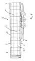
- Fig. 1 is shown as an example of a vehicle to be equipped with a construction according to the invention a semi-trailer 1.
- the semi-trailer 1 has a box-like structure 2, which is bounded by side walls, a floor and a ceiling, of which here a side wall 3 is shown and the bottom 4 and the ceiling 4 are indicated.
- a side wall 3 is shown and the bottom 4 and the ceiling 4 are indicated.
- At the rear end face of the structure 2 is provided with an access opening to the interior, which is closable with correspondingly insulated doors.
- the structure 2 of the semitrailer 1 is provided on the side walls, the bottom 4 and the ceiling 5 with a wall structure which provides a vacuum insulation panel 7 arranged between the layers.
- the assembly with individual vacuum insulation panels 7 is indicated here by dashed lines 6 fields are shown, which are occupied with vacuum insulation panels 7.
- the vacuum insulation panels 7 are actually in the in Fig. 1 shown side view not visible, they are covered by a continuous cover layer, which consists in accordance with the invention of a carbon fiber composite material (CFRP).
- CFRP carbon fiber composite material
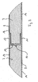
- a section of a wall is shown in a cross section, which shows how the vacuum insulation panels 7 are arranged between two comparatively thin cover layers 8, 9 which each consist of CFRP.
- a U-shaped support profile 10 which abuts with its lateral limbs 11 and 12 respectively on the inside of the cover layers 8 and 9 and is firmly connected thereto.
- the base 13 of the support section 10 is thin and runs through the otherwise filled with vacuum insulation panels 7 space between the cover layers 8 and 9.
- the support section 10 is made of a carbon fiber composite material (CFRP), bringing its excellent material properties in terms of strength and stability on the one hand and Light weight on the other hand with it.
- CFRP carbon fiber composite material
- the vacuum insulation panel 7 shown on the right in the region where it lies between the legs 11 and 12 is formed at a reduced thickness, so that the surfaces of the vacuum insulation panel 7 and the legs 11 and 12 are aligned with each other on the side adjacent to the cover layers 8 and 9, respectively.
- the entire structure is connected to each other by adhesive bonding, ie, the vacuum insulation panels 7 are bonded to the support section 10, the cover layers 8 and 9 glued to the surfaces of the vacuum insulation panels 7.
- the adhesive forms a surface protective layer that avoids direct contact and in particular rubbing together of CFK elements formed covering layer 8, cover layer 9 and support profile 10 with the adjacent vacuum insulation panels 7 so as to protect the sensitive surface of these vacuum insulation panels 7, which typically consists of a Aluminum composite foil is formed, to spare. Because this surface encloses a highly porous material attached in the core of the vacuum insulation panels 7 in a vacuum-tight manner and thus maintains the negative pressure in the evacuated region of the core. This negative pressure results in the thermal insulation properties of the vacuum insulation panels 7, the equipment of the surfaces with an aluminum composite film also provides protection against heat loss by radiation.
- the in Fig. 2 The structure shown is characterized in that the entire wall is formed solely by a centrally arranged layer of juxtaposed vacuum insulation panels 7 and outer and inner side disposed thereon cover layers 8 and 9, wherein the layers form a surface protective layer here.
- the support profiles 10 are provided, which are arranged in a direction parallel to each other extending at each interface between adjacent vacuum insulation panels 7.
- Fig. 3 is one of the Fig. 2 basically comparable embodiment shown, here vacuum insulation panels 7 are arranged in the same way between the broad sides on the inside and outside applied cover layers 8 and 9 made of CFK and below a support structure 10 is provided on the front side in the joint area of the vacuum insulation panel 7. Again, the elements are firmly connected to each other by gluing. So far, this embodiment is equal to the above in Fig. 2 described. The only difference to that in Fig. 2 shown embodiment is that the vacuum insulation panels 7 are provided to protect their sensitive surfaces with a surface protective layer in the form of a Vlieskaschtechnik 14.
- FIG Fig. 4 shows a schematic three-dimensional sectional view in FIG Fig. 4 shows.
- the stabilization of the construction and formation of a connection between the facing layers lying opposite one another is formed here by a first alternating cover layer 15.
- This runs alternately at a first vacuum insulation panel 7 on the inside and a second, on the first vacuum insulation panel 7 frontally abutting vacuum insulation panel 7 on the outside of the wall construction.
- the alternating cover layer 15 is deflected and forms a web 16, which forms a sheet-like thin connecting web between the individual cover layers and thus the desired stabilization, the adjacent vacuum insulation panels 7 abut against this web 16.
- cover layers on the inside and the outside are thus formed in this construction from the alternating cover layer on the respective side and the upper cover layer elements placed thereon.
Claims (11)
- Structure pour véhicule de transport (1), en particulier pour véhicule de transport frigorifique, comprenant des parois latérales (3), un fond (4) et un plafond (5) entourant une partie interne, où les parois latérales (3) et/ou le sol (4) et/ou le plafond (5) sont pourvus d'une couche de revêtement interne et d'une couche de respectivement externe, respectivement continues (8, 9; 15) et de panneaux d'isolation sous vide (7) disposée entre lesdites couches, caractérisée en ce que les couches de revêtement (8, 9, 15) sont des couches de matériau composite renforcé de fibre de carbone (CFK) qui sont appliquées directement aux surfaces internes et externes du panneau d'isolation sous vide (7), le cas échéant en intercalant une couche de protection de surface pour protéger des surfaces résistantes aux rayures et aux chocs des panneaux d'isolation sous vide (7), respectivement à l'exclusion d'autres couches d'isolation ou d'appui.
- Structure selon la revendication 1, caractérisée en ce que les panneaux d'isolation sous vide (7) sont collés directement avec les couches de revêtement (8, 9; 15) et les couches d'adhésif constituent respectivement une couche de protection de surface.
- Structure selon la revendication 1, caractérisée en ce qu'une couche de textile, en particulier un voile de doublure (14) est prévu entre les surfaces des panneaux d'isolation sous vide (7) et au moins l'une des couches de revêtement (8, 9) de préférence les deux couches de revêtement (8, 9).
- Structure selon l'une quelconque des revendications précédentes, caractérisée en ce que systématiquement dans une direction passant entre les faces frontales de panneaux d'isolation sous vide limitrophes (7) des structures d'appui (10; 16) sont prévues, solidaires des deux couches de revêtement (8, 9; 15) et disposés sous forme de tôles minces dans l'espace entre les faces frontales des panneaux d'isolation sous vide (7) limitrophes.
- Structure selon la revendication 4, caractérisée en ce que les structures d'appui (10; 15) consistent d'un matériau composite renforcé de fibre de carbone (CFK).
- Structure selon l'une des revendications 4 ou 5, caractérisée en ce que les structures d'appui sont constituées de profils en U disposés entre les couches de revêtement (8, 9), reposant contre chacune des couches de revêtement (8, 9) avec respectivement une branche (11, 12) et solidaires desdites couches, en particulier collées à celles-ci, à la base (13) de laquelle butent les faces frontales limitrophes de panneaux d'isolation sous vide voisins (7).
- Structure selon la revendication 6, caractérisée en ce que l'épaisseur des sections frontales des panneaux d'isolation sous vide (7) concernés et reposant par leurs extrémités entre les branches (11, 12) du profil en forme de U sera réduite de sorte que les surfaces des panneaux d'isolation sous vide (7), le cas échéant avec la couche intermédiaire appliquée, et des branches (11, 12) du profil en U vont affleurer dans cette zone.
- Structure selon l'une des revendications 4 ou 5, caractérisée en ce que les structures d'appui (16) sont constituées de structures de profil passant entre les couches de revêtement (15) en forme de Z et solidaires des couches de revêtement (15) par leurs faces externes.
- Structure selon l'une quelconque des revendications précédentes, caractérisée en ce que les panneaux d'isolation sous vide (7) présentent respectivement un matériau de noyau en forme de plaque, stable en pression et extrêmement poreux et un film scellant hermétiquement les surfaces du matériau de noyau et de manière complètement étanche au vide, tandis que la zone du matériau de noyau est évacuée.
- Structure selon l'une quelconque des revendications précédentes, caractérisée en ce qu'elle présente une épaisseur totale comprise entre 5 et 20 mm, de préférence d'environ 15 mm, mesurée depuis la face externe libre de la couche de revêtement externe (8, 9) jusqu'à la face externe libre opposée de la couche de revêtement interne (8, 9).
- Véhicule de transport frigorifique avec une structure selon l'une des revendications 1 à 10.
Priority Applications (1)
| Application Number | Priority Date | Filing Date | Title |
|---|---|---|---|
| EP20100155122 EP2363337B1 (fr) | 2010-03-02 | 2010-03-02 | Structure pour un véhicule de transport et véhicule de transport frigorifique doté d'une telle structure |
Applications Claiming Priority (1)
| Application Number | Priority Date | Filing Date | Title |
|---|---|---|---|
| EP20100155122 EP2363337B1 (fr) | 2010-03-02 | 2010-03-02 | Structure pour un véhicule de transport et véhicule de transport frigorifique doté d'une telle structure |
Publications (2)
| Publication Number | Publication Date |
|---|---|
| EP2363337A1 EP2363337A1 (fr) | 2011-09-07 |
| EP2363337B1 true EP2363337B1 (fr) | 2015-05-06 |
Family
ID=42710727
Family Applications (1)
| Application Number | Title | Priority Date | Filing Date |
|---|---|---|---|
| EP20100155122 Not-in-force EP2363337B1 (fr) | 2010-03-02 | 2010-03-02 | Structure pour un véhicule de transport et véhicule de transport frigorifique doté d'une telle structure |
Country Status (1)
| Country | Link |
|---|---|
| EP (1) | EP2363337B1 (fr) |
Families Citing this family (2)
| Publication number | Priority date | Publication date | Assignee | Title |
|---|---|---|---|---|
| DE102013101584B4 (de) * | 2013-02-18 | 2021-01-21 | Kögel Trailer GmbH | Bodenelement für einen Nutzfahrzeugaufbau und Nutzfahrzeugaufbau oder Nutzfahrzeug mit einem derartigen Bodenelement |
| CN104015814A (zh) * | 2014-06-16 | 2014-09-03 | 江苏恒神纤维材料有限公司 | 碳纤维车厢结构 |
Family Cites Families (8)
| Publication number | Priority date | Publication date | Assignee | Title |
|---|---|---|---|---|
| DE1630595A1 (de) * | 1967-06-08 | 1971-08-05 | Koegel Gmbh Fahrzeug | Behaelter- und/oder Kastenaufbau,insbesondere fuer Kraftfahrzeuge |
| DE19803908A1 (de) * | 1998-02-02 | 1999-08-05 | Thyssen Vakuum Isolationstechn | Plattenförmiger Formkörper zur Wärmeisolierung von Räumen, Behältern oder dergl. |
| US6093481A (en) * | 1998-03-06 | 2000-07-25 | Celotex Corporation | Insulating sheathing with tough three-ply facers |
| FR2807379A1 (fr) * | 2000-04-07 | 2001-10-12 | Richard Turmel | Carrosserie isolee et frigorifique pour vehicule |
| AU2003229243A1 (en) * | 2002-06-24 | 2004-01-06 | Sager Ag | Vacuum insulation panel, method for the heat insulation of objects and auxiliary agent therefor |
| DE102005054538A1 (de) | 2005-11-14 | 2007-05-16 | Fahrzeugwerk Bernard Krone | Aufbau für Transportfahrzeuge |
| US8342588B2 (en) * | 2007-01-24 | 2013-01-01 | Martin Marietta Materials, Inc. | Insulated composite body panel structure for a refrigerated truck body |
| DE202009016007U1 (de) * | 2009-11-25 | 2010-02-25 | Alberth, Günter | Paneel für Kühlboxen |
-
2010
- 2010-03-02 EP EP20100155122 patent/EP2363337B1/fr not_active Not-in-force
Also Published As
| Publication number | Publication date |
|---|---|
| EP2363337A1 (fr) | 2011-09-07 |
Similar Documents
| Publication | Publication Date | Title |
|---|---|---|
| DE102007035228B4 (de) | Transportbehälter | |
| EP1785337B1 (fr) | Compartiment de charge de véhicule utilitaire | |
| EP1181421A1 (fr) | Element de construction leger sous forme d'une structure en nid d'abeilles profilee a corps creux | |
| EP1301669A1 (fr) | Element de construction autoporteur et porteur de charge | |
| DE102006049482A1 (de) | Container-Bodenplatte, insbesondere für einen Kühlcontainer | |
| EP2363337B1 (fr) | Structure pour un véhicule de transport et véhicule de transport frigorifique doté d'une telle structure | |
| DE202012104182U1 (de) | Bahn aus mehrlagigem Dämmstoff, Bahn aus Dämmverbund, der aus derartigen Bahnen aus mehrlagigem Dämmstoff gebildet ist | |
| EP1465820B1 (fr) | Conteneur | |
| EP2927159B1 (fr) | Conteneur de transport autoporteur et son procédé de fabrication | |
| EP2678490B1 (fr) | Élément structural léger porteur | |
| DE202019102768U1 (de) | Dachfenster-Konstruktionssystem | |
| DE102008016345A1 (de) | Mehrschichtiges Bauelement | |
| DE102009038320A1 (de) | Dämmplatte | |
| DE1658887C3 (de) | Nichttragende, mehrschichtige Gebäude-AuBenwandung, z.B. Vorhangwand od. dgl | |
| DE3308941C2 (de) | Plattenförmiges Wärmedämmelement | |
| EP3601696A2 (fr) | Plaque de construction résistante à la chaleur et à la compression | |
| DE2441392A1 (de) | Speichertank fuer fluessiggas | |
| DE102021128315A1 (de) | Fahrzeugaufbau, insbesondere eines Kühlfahrzeugs, Baukastensystem zur Herstellung eines solchen Fahrzeugaufbaus sowie Herstellungsverfahren | |
| CH655346A5 (de) | Tragendes bauelement fuer decken oder daecher. | |
| DE653742C (de) | Zellenbaukoerper aus ineinandergreifenden, aus faltbarem Werkstoff hergestellten Stegplatten | |
| EP2927102A2 (fr) | Auge de transport destinée au transport de matériaux chauds | |
| DE102014114559A1 (de) | Raumzelle | |
| DE102009002404B4 (de) | Biegeträger zur Bildung einer Bodenplatte eines Frachtraumbodens eines Flugzeuges, Bodenplatte mit einem solchen Biegeträger und Flugzeug mit einem solchen Biegeträger | |
| DE202013011344U1 (de) | Bauelement | |
| DE19616369C1 (de) | Plattenbauelement und Dachkonstruktion,bestehend aus derartigen Plattenbauelementen |
Legal Events
| Date | Code | Title | Description |
|---|---|---|---|
| PUAI | Public reference made under article 153(3) epc to a published international application that has entered the european phase |
Free format text: ORIGINAL CODE: 0009012 |
|
| AK | Designated contracting states |
Kind code of ref document: A1 Designated state(s): AT BE BG CH CY CZ DE DK EE ES FI FR GB GR HR HU IE IS IT LI LT LU LV MC MK MT NL NO PL PT RO SE SI SK SM TR |
|
| AX | Request for extension of the european patent |
Extension state: AL BA ME RS |
|
| 17P | Request for examination filed |
Effective date: 20120111 |
|
| 17Q | First examination report despatched |
Effective date: 20120215 |
|
| APBK | Appeal reference recorded |
Free format text: ORIGINAL CODE: EPIDOSNREFNE |
|
| APBN | Date of receipt of notice of appeal recorded |
Free format text: ORIGINAL CODE: EPIDOSNNOA2E |
|
| APBR | Date of receipt of statement of grounds of appeal recorded |
Free format text: ORIGINAL CODE: EPIDOSNNOA3E |
|
| APAF | Appeal reference modified |
Free format text: ORIGINAL CODE: EPIDOSCREFNE |
|
| APBX | Invitation to file observations in appeal sent |
Free format text: ORIGINAL CODE: EPIDOSNOBA2E |
|
| APBT | Appeal procedure closed |
Free format text: ORIGINAL CODE: EPIDOSNNOA9E |
|
| GRAP | Despatch of communication of intention to grant a patent |
Free format text: ORIGINAL CODE: EPIDOSNIGR1 |
|
| INTG | Intention to grant announced |
Effective date: 20150127 |
|
| GRAS | Grant fee paid |
Free format text: ORIGINAL CODE: EPIDOSNIGR3 |
|
| GRAA | (expected) grant |
Free format text: ORIGINAL CODE: 0009210 |
|
| AK | Designated contracting states |
Kind code of ref document: B1 Designated state(s): AT BE BG CH CY CZ DE DK EE ES FI FR GB GR HR HU IE IS IT LI LT LU LV MC MK MT NL NO PL PT RO SE SI SK SM TR |
|
| REG | Reference to a national code |
Ref country code: GB Ref legal event code: FG4D Free format text: NOT ENGLISH |
|
| REG | Reference to a national code |
Ref country code: CH Ref legal event code: EP |
|
| REG | Reference to a national code |
Ref country code: IE Ref legal event code: FG4D Free format text: LANGUAGE OF EP DOCUMENT: GERMAN |
|
| REG | Reference to a national code |
Ref country code: AT Ref legal event code: REF Ref document number: 725472 Country of ref document: AT Kind code of ref document: T Effective date: 20150615 |
|
| REG | Reference to a national code |
Ref country code: DE Ref legal event code: R096 Ref document number: 502010009465 Country of ref document: DE Effective date: 20150618 |
|
| REG | Reference to a national code |
Ref country code: NL Ref legal event code: T3 |
|
| REG | Reference to a national code |
Ref country code: LT Ref legal event code: MG4D |
|
| PG25 | Lapsed in a contracting state [announced via postgrant information from national office to epo] |
Ref country code: PT Free format text: LAPSE BECAUSE OF FAILURE TO SUBMIT A TRANSLATION OF THE DESCRIPTION OR TO PAY THE FEE WITHIN THE PRESCRIBED TIME-LIMIT Effective date: 20150907 Ref country code: ES Free format text: LAPSE BECAUSE OF FAILURE TO SUBMIT A TRANSLATION OF THE DESCRIPTION OR TO PAY THE FEE WITHIN THE PRESCRIBED TIME-LIMIT Effective date: 20150506 Ref country code: LT Free format text: LAPSE BECAUSE OF FAILURE TO SUBMIT A TRANSLATION OF THE DESCRIPTION OR TO PAY THE FEE WITHIN THE PRESCRIBED TIME-LIMIT Effective date: 20150506 Ref country code: FI Free format text: LAPSE BECAUSE OF FAILURE TO SUBMIT A TRANSLATION OF THE DESCRIPTION OR TO PAY THE FEE WITHIN THE PRESCRIBED TIME-LIMIT Effective date: 20150506 Ref country code: NO Free format text: LAPSE BECAUSE OF FAILURE TO SUBMIT A TRANSLATION OF THE DESCRIPTION OR TO PAY THE FEE WITHIN THE PRESCRIBED TIME-LIMIT Effective date: 20150806 Ref country code: HR Free format text: LAPSE BECAUSE OF FAILURE TO SUBMIT A TRANSLATION OF THE DESCRIPTION OR TO PAY THE FEE WITHIN THE PRESCRIBED TIME-LIMIT Effective date: 20150506 |
|
| PG25 | Lapsed in a contracting state [announced via postgrant information from national office to epo] |
Ref country code: LV Free format text: LAPSE BECAUSE OF FAILURE TO SUBMIT A TRANSLATION OF THE DESCRIPTION OR TO PAY THE FEE WITHIN THE PRESCRIBED TIME-LIMIT Effective date: 20150506 Ref country code: BG Free format text: LAPSE BECAUSE OF FAILURE TO SUBMIT A TRANSLATION OF THE DESCRIPTION OR TO PAY THE FEE WITHIN THE PRESCRIBED TIME-LIMIT Effective date: 20150806 Ref country code: IS Free format text: LAPSE BECAUSE OF FAILURE TO SUBMIT A TRANSLATION OF THE DESCRIPTION OR TO PAY THE FEE WITHIN THE PRESCRIBED TIME-LIMIT Effective date: 20150906 Ref country code: GR Free format text: LAPSE BECAUSE OF FAILURE TO SUBMIT A TRANSLATION OF THE DESCRIPTION OR TO PAY THE FEE WITHIN THE PRESCRIBED TIME-LIMIT Effective date: 20150807 |
|
| PG25 | Lapsed in a contracting state [announced via postgrant information from national office to epo] |
Ref country code: DK Free format text: LAPSE BECAUSE OF FAILURE TO SUBMIT A TRANSLATION OF THE DESCRIPTION OR TO PAY THE FEE WITHIN THE PRESCRIBED TIME-LIMIT Effective date: 20150506 Ref country code: EE Free format text: LAPSE BECAUSE OF FAILURE TO SUBMIT A TRANSLATION OF THE DESCRIPTION OR TO PAY THE FEE WITHIN THE PRESCRIBED TIME-LIMIT Effective date: 20150506 |
|
| REG | Reference to a national code |
Ref country code: DE Ref legal event code: R097 Ref document number: 502010009465 Country of ref document: DE |
|
| PG25 | Lapsed in a contracting state [announced via postgrant information from national office to epo] |
Ref country code: RO Free format text: LAPSE BECAUSE OF NON-PAYMENT OF DUE FEES Effective date: 20150506 Ref country code: SK Free format text: LAPSE BECAUSE OF FAILURE TO SUBMIT A TRANSLATION OF THE DESCRIPTION OR TO PAY THE FEE WITHIN THE PRESCRIBED TIME-LIMIT Effective date: 20150506 Ref country code: PL Free format text: LAPSE BECAUSE OF FAILURE TO SUBMIT A TRANSLATION OF THE DESCRIPTION OR TO PAY THE FEE WITHIN THE PRESCRIBED TIME-LIMIT Effective date: 20150506 Ref country code: CZ Free format text: LAPSE BECAUSE OF FAILURE TO SUBMIT A TRANSLATION OF THE DESCRIPTION OR TO PAY THE FEE WITHIN THE PRESCRIBED TIME-LIMIT Effective date: 20150506 |
|
| PLBE | No opposition filed within time limit |
Free format text: ORIGINAL CODE: 0009261 |
|
| STAA | Information on the status of an ep patent application or granted ep patent |
Free format text: STATUS: NO OPPOSITION FILED WITHIN TIME LIMIT |
|
| REG | Reference to a national code |
Ref country code: FR Ref legal event code: PLFP Year of fee payment: 7 |
|
| 26N | No opposition filed |
Effective date: 20160209 |
|
| PG25 | Lapsed in a contracting state [announced via postgrant information from national office to epo] |
Ref country code: IT Free format text: LAPSE BECAUSE OF FAILURE TO SUBMIT A TRANSLATION OF THE DESCRIPTION OR TO PAY THE FEE WITHIN THE PRESCRIBED TIME-LIMIT Effective date: 20150506 |
|
| PG25 | Lapsed in a contracting state [announced via postgrant information from national office to epo] |
Ref country code: SI Free format text: LAPSE BECAUSE OF FAILURE TO SUBMIT A TRANSLATION OF THE DESCRIPTION OR TO PAY THE FEE WITHIN THE PRESCRIBED TIME-LIMIT Effective date: 20150506 |
|
| PG25 | Lapsed in a contracting state [announced via postgrant information from national office to epo] |
Ref country code: BE Free format text: LAPSE BECAUSE OF NON-PAYMENT OF DUE FEES Effective date: 20160331 |
|
| PG25 | Lapsed in a contracting state [announced via postgrant information from national office to epo] |
Ref country code: MC Free format text: LAPSE BECAUSE OF FAILURE TO SUBMIT A TRANSLATION OF THE DESCRIPTION OR TO PAY THE FEE WITHIN THE PRESCRIBED TIME-LIMIT Effective date: 20150506 Ref country code: LU Free format text: LAPSE BECAUSE OF FAILURE TO SUBMIT A TRANSLATION OF THE DESCRIPTION OR TO PAY THE FEE WITHIN THE PRESCRIBED TIME-LIMIT Effective date: 20160302 |
|
| REG | Reference to a national code |
Ref country code: CH Ref legal event code: PL |
|
| REG | Reference to a national code |
Ref country code: IE Ref legal event code: MM4A |
|
| PG25 | Lapsed in a contracting state [announced via postgrant information from national office to epo] |
Ref country code: CH Free format text: LAPSE BECAUSE OF NON-PAYMENT OF DUE FEES Effective date: 20160331 Ref country code: LI Free format text: LAPSE BECAUSE OF NON-PAYMENT OF DUE FEES Effective date: 20160331 Ref country code: IE Free format text: LAPSE BECAUSE OF NON-PAYMENT OF DUE FEES Effective date: 20160302 |
|
| REG | Reference to a national code |
Ref country code: FR Ref legal event code: PLFP Year of fee payment: 8 |
|
| PG25 | Lapsed in a contracting state [announced via postgrant information from national office to epo] |
Ref country code: SE Free format text: LAPSE BECAUSE OF FAILURE TO SUBMIT A TRANSLATION OF THE DESCRIPTION OR TO PAY THE FEE WITHIN THE PRESCRIBED TIME-LIMIT Effective date: 20150506 |
|
| PG25 | Lapsed in a contracting state [announced via postgrant information from national office to epo] |
Ref country code: MT Free format text: LAPSE BECAUSE OF FAILURE TO SUBMIT A TRANSLATION OF THE DESCRIPTION OR TO PAY THE FEE WITHIN THE PRESCRIBED TIME-LIMIT Effective date: 20150506 |
|
| REG | Reference to a national code |
Ref country code: FR Ref legal event code: PLFP Year of fee payment: 9 |
|
| PG25 | Lapsed in a contracting state [announced via postgrant information from national office to epo] |
Ref country code: HU Free format text: LAPSE BECAUSE OF FAILURE TO SUBMIT A TRANSLATION OF THE DESCRIPTION OR TO PAY THE FEE WITHIN THE PRESCRIBED TIME-LIMIT; INVALID AB INITIO Effective date: 20100302 Ref country code: SM Free format text: LAPSE BECAUSE OF FAILURE TO SUBMIT A TRANSLATION OF THE DESCRIPTION OR TO PAY THE FEE WITHIN THE PRESCRIBED TIME-LIMIT Effective date: 20150506 Ref country code: CY Free format text: LAPSE BECAUSE OF FAILURE TO SUBMIT A TRANSLATION OF THE DESCRIPTION OR TO PAY THE FEE WITHIN THE PRESCRIBED TIME-LIMIT Effective date: 20150506 |
|
| PG25 | Lapsed in a contracting state [announced via postgrant information from national office to epo] |
Ref country code: TR Free format text: LAPSE BECAUSE OF FAILURE TO SUBMIT A TRANSLATION OF THE DESCRIPTION OR TO PAY THE FEE WITHIN THE PRESCRIBED TIME-LIMIT Effective date: 20150506 Ref country code: MK Free format text: LAPSE BECAUSE OF FAILURE TO SUBMIT A TRANSLATION OF THE DESCRIPTION OR TO PAY THE FEE WITHIN THE PRESCRIBED TIME-LIMIT Effective date: 20150506 |
|
| REG | Reference to a national code |
Ref country code: DE Ref legal event code: R082 Ref document number: 502010009465 Country of ref document: DE |
|
| PGFP | Annual fee paid to national office [announced via postgrant information from national office to epo] |
Ref country code: GB Payment date: 20220324 Year of fee payment: 13 Ref country code: DE Payment date: 20220322 Year of fee payment: 13 Ref country code: AT Payment date: 20220318 Year of fee payment: 13 |
|
| PGFP | Annual fee paid to national office [announced via postgrant information from national office to epo] |
Ref country code: NL Payment date: 20220322 Year of fee payment: 13 Ref country code: FR Payment date: 20220322 Year of fee payment: 13 |
|
| REG | Reference to a national code |
Ref country code: DE Ref legal event code: R119 Ref document number: 502010009465 Country of ref document: DE |
|
| REG | Reference to a national code |
Ref country code: NL Ref legal event code: MM Effective date: 20230401 |
|
| REG | Reference to a national code |
Ref country code: AT Ref legal event code: MM01 Ref document number: 725472 Country of ref document: AT Kind code of ref document: T Effective date: 20230302 |
|
| GBPC | Gb: european patent ceased through non-payment of renewal fee |
Effective date: 20230302 |
|
| PG25 | Lapsed in a contracting state [announced via postgrant information from national office to epo] |
Ref country code: NL Free format text: LAPSE BECAUSE OF NON-PAYMENT OF DUE FEES Effective date: 20230401 |
|
| PG25 | Lapsed in a contracting state [announced via postgrant information from national office to epo] |
Ref country code: GB Free format text: LAPSE BECAUSE OF NON-PAYMENT OF DUE FEES Effective date: 20230302 |
|
| PG25 | Lapsed in a contracting state [announced via postgrant information from national office to epo] |
Ref country code: GB Free format text: LAPSE BECAUSE OF NON-PAYMENT OF DUE FEES Effective date: 20230302 Ref country code: FR Free format text: LAPSE BECAUSE OF NON-PAYMENT OF DUE FEES Effective date: 20230331 Ref country code: DE Free format text: LAPSE BECAUSE OF NON-PAYMENT OF DUE FEES Effective date: 20231003 Ref country code: AT Free format text: LAPSE BECAUSE OF NON-PAYMENT OF DUE FEES Effective date: 20230302 |