EP2927102A2 - Auge de transport destinée au transport de matériaux chauds - Google Patents
Auge de transport destinée au transport de matériaux chauds Download PDFInfo
- Publication number
- EP2927102A2 EP2927102A2 EP15000881.1A EP15000881A EP2927102A2 EP 2927102 A2 EP2927102 A2 EP 2927102A2 EP 15000881 A EP15000881 A EP 15000881A EP 2927102 A2 EP2927102 A2 EP 2927102A2
- Authority
- EP
- European Patent Office
- Prior art keywords
- profile
- transport
- cover layers
- trough
- spacer
- Prior art date
- Legal status (The legal status is an assumption and is not a legal conclusion. Google has not performed a legal analysis and makes no representation as to the accuracy of the status listed.)
- Withdrawn
Links
- 125000006850 spacer group Chemical group 0.000 claims abstract description 26
- 239000010426 asphalt Substances 0.000 claims abstract description 12
- 239000007787 solid Substances 0.000 claims abstract description 4
- 230000000087 stabilizing effect Effects 0.000 claims abstract description 4
- 229910052751 metal Inorganic materials 0.000 claims abstract description 3
- 239000002184 metal Substances 0.000 claims abstract description 3
- 230000007704 transition Effects 0.000 claims description 10
- WSFSSNUMVMOOMR-UHFFFAOYSA-N Formaldehyde Chemical compound O=C WSFSSNUMVMOOMR-UHFFFAOYSA-N 0.000 claims description 6
- 239000000463 material Substances 0.000 claims description 6
- 239000006260 foam Substances 0.000 claims description 5
- 239000000203 mixture Substances 0.000 claims description 5
- 229920005830 Polyurethane Foam Polymers 0.000 claims description 4
- 239000011810 insulating material Substances 0.000 claims description 4
- 239000011490 mineral wool Substances 0.000 claims description 4
- 239000004033 plastic Substances 0.000 claims description 4
- 229920003023 plastic Polymers 0.000 claims description 4
- 239000011496 polyurethane foam Substances 0.000 claims description 4
- 239000012774 insulation material Substances 0.000 claims description 3
- 239000004640 Melamine resin Substances 0.000 claims description 2
- 229920000877 Melamine resin Polymers 0.000 claims description 2
- 239000011491 glass wool Substances 0.000 claims description 2
- ISWSIDIOOBJBQZ-UHFFFAOYSA-N phenol group Chemical group C1(=CC=CC=C1)O ISWSIDIOOBJBQZ-UHFFFAOYSA-N 0.000 claims description 2
- 229920005989 resin Polymers 0.000 claims description 2
- 239000011347 resin Substances 0.000 claims description 2
- 229910000838 Al alloy Inorganic materials 0.000 claims 1
- 238000009413 insulation Methods 0.000 description 11
- 229910052782 aluminium Inorganic materials 0.000 description 3
- XAGFODPZIPBFFR-UHFFFAOYSA-N aluminium Chemical compound [Al] XAGFODPZIPBFFR-UHFFFAOYSA-N 0.000 description 3
- 238000010276 construction Methods 0.000 description 2
- 238000004519 manufacturing process Methods 0.000 description 2
- 230000003014 reinforcing effect Effects 0.000 description 2
- 229920000965 Duroplast Polymers 0.000 description 1
- 239000004638 Duroplast Substances 0.000 description 1
- 238000004026 adhesive bonding Methods 0.000 description 1
- 239000004566 building material Substances 0.000 description 1
- 150000001875 compounds Chemical class 0.000 description 1
- 238000001816 cooling Methods 0.000 description 1
- 238000011161 development Methods 0.000 description 1
- 230000018109 developmental process Effects 0.000 description 1
- 238000005187 foaming Methods 0.000 description 1
- 238000011065 in-situ storage Methods 0.000 description 1
- 238000011900 installation process Methods 0.000 description 1
- 238000005304 joining Methods 0.000 description 1
- 230000007774 longterm Effects 0.000 description 1
- 230000002787 reinforcement Effects 0.000 description 1
- 230000008646 thermal stress Effects 0.000 description 1
- 229920001187 thermosetting polymer Polymers 0.000 description 1
- 238000003466 welding Methods 0.000 description 1
Images


Classifications
-
- B—PERFORMING OPERATIONS; TRANSPORTING
- B62—LAND VEHICLES FOR TRAVELLING OTHERWISE THAN ON RAILS
- B62D—MOTOR VEHICLES; TRAILERS
- B62D33/00—Superstructures for load-carrying vehicles
- B62D33/04—Enclosed load compartments ; Frameworks for movable panels, tarpaulins or side curtains
- B62D33/046—Enclosed load compartments ; Frameworks for movable panels, tarpaulins or side curtains built up with flat self-supporting panels; Fixed connections between panels
-
- B—PERFORMING OPERATIONS; TRANSPORTING
- B60—VEHICLES IN GENERAL
- B60P—VEHICLES ADAPTED FOR LOAD TRANSPORTATION OR TO TRANSPORT, TO CARRY, OR TO COMPRISE SPECIAL LOADS OR OBJECTS
- B60P1/00—Vehicles predominantly for transporting loads and modified to facilitate loading, consolidating the load, or unloading
- B60P1/04—Vehicles predominantly for transporting loads and modified to facilitate loading, consolidating the load, or unloading with a tipping movement of load-transporting element
- B60P1/28—Tipping body constructions
- B60P1/283—Elements of tipping devices
- B60P1/286—Loading buckets
Definitions
- the invention relates to a transport tray for the transport of hot goods, such as asphalt, bitumen and / or Asphaltmischgut comprising a trough bottom, two side walls, an end wall and a rear wall, wherein at least the side walls are each formed of thermally decoupled metal cover layers between which a Insulating layer of low thermal conductivity is arranged.
- the invention also relates to a semitrailer or trailer equipped with such a transport trough.
- a transport tray of the type described in the preamble can be the EP 0 375 621 A1 remove.
- the known solution proposes the attachment of additional center posts.
- the additional center posts are formed in two parts and reinforce the dump body from the outside and inside.
- the mullions thus exert a compressive force on the side wall from outside and inside.
- the well walls are characterized by a considerable weight and a complex and expensive construction, but have insufficient mechanical stability.
- the dump body is not very suitable because the well walls can deform as a result of thermal stress, in particular between the mullions.
- the transport troughs are to be thermally insulated.
- the use of thermally insulated half-round wells is advantageous, since - due to the geometry - less critical adhesion points of the bituminous mixture in the corners of the trough exist. Nevertheless box casks are considered equivalent.
- the wall / trough structure including the insulating material used must at least one Thermal resistance (R-value) of ⁇ 1.65 m 2 K / W at 20 ° C.
- the insulation material used must have a long-term temperature resistance up to 200 ° C.
- the object of the invention is to develop a transport trough of the type mentioned, the trough walls manage without additional lateral reinforcements and still ensure sufficient mechanical stability.
- the transport well should meet the legal requirements.
- the spacer profiles are made of a material with low thermal conductivity and high temperature resistance.
- the material is a solid plastic element having the stated properties, such as a solid rod with elongated grooves for receiving retaining profiles.
- the holding profiles can be joined to the cover layers or in a piece of material with the cover layers, e.g. be designed as extruded profile.
- a connection of the holding profile with the cover layer can be done by riveting, screwing, preferably by gluing or welding.
- Foamed plastic such as polyurethane foam, phenolic hard foam, melamine resin foam, formaldehyde resin, inorganic thermal insulation material, such as mineral wool, rockwool or glass wool or high-temperature nonwoven, is suitable as the insulating material.
- the transport tray according to the invention allows a uniform discharge, especially in an asphalt animal machine.
- the hot material cools only slightly on the way to the unloading point. Also in the other, aligned perpendicular to the well bottom transition areas on the trough wall do not form cold spots that could cause a reduced quality of laid asphalt surface.
- inventive concept can make good service in the production of refrigerated vehicles for road or rail transport.
- FIGS. 1 and 4 a box-like transport tray 100 of a dump truck, not shown, is shown schematically, comprising two elongated side walls 4, a rear wall 9 (tailgate), an end wall 19 and a trough bottom 10. All these parts of the transport tray 100 are each insulated with an insulating layer 1 of low thermal conductivity.
- the insulation layers 1 in the form of prefabricated polyurethane foam boards are inserted between two spaced cover layers 2, 3 of the side walls 4 and between an inner and outer aluminum sheet 17, 18 of the trough bottom 10. Foaming in situ is also possible if the thermal insulation is to consist of polymeric foams.
- the insulating layer 1 consists in the present case of foamed, inexpensive polyurethane foam sheets.
- the cover layer 2 is directed in the assembled state of the transport tray 100 on the trough bottom 10, whereas the second, outer cover layer 3 forms an outer skin of the side wall 4.
- the two cover layers 2, 3 are made of aluminum and can be referred to as "aluminum sheets”.
- FIG. 2 shows, on the side wall 4 at predetermined intervals perpendicular to the trough bottom 10 extending holding profiles 8 and 8 'are arranged, which according to Figures 3 and 16 are manufactured as C-profiles.
- the C-profiles each have a middle web 27 which is preferably glued or welded to the cover layer 2 and 3 and two inwardly angled C-legs 11, 11 ', which engage in corresponding grooves 6, 6', 7, 7 'of a spacing profile 5 ,
- FIG. 14 C-shaped retaining profiles 8, 8 'are shown, which are directed with their C-legs 32 in the longitudinal direction of the side wall 4.
- the holding profiles 8, 8 'can also be L-shaped or Z-shaped (cf. Fig. 15 ). It is important that the holding profiles 8, 8 'can be positively connected to the spacer profiles 5.
- the in Fig. 16 shown holding and spacer profiles to be the cheapest.
- the spacer profile 5 is made of a heat-insulating, heat-resistant plastic, preferably made of thermosetting plastic Duroplast.
- the thermo-insulating spacer profile 5 acts as a mechanically stabilizing, tensile-force-transmitting reinforcing element. In this way, the two cover layers 2, 3, including the holding profiles 8, 8 'fastened thereto, can be mechanically connected to one another and thermally decoupled from one another.
- a transition region 22 between the trough bottom 10 and side walls 4 by a rectangular profile piece 21 with a slope 28 (see. Fig. 7 ), the latter in turn comprising an inner panel 24, an outer panel 25 and an insulating layer 29 therebetween, but without spacer profiles.
- a tapered transition region 23 is provided, which, however, perpendicular to the trough bottom 10 extends.
- a particularly stable side wall 26 is shown, which consists of an already described, with holding and spacing profiles 8, 8 '; 5 reinforced, fully thermally insulated side wall 4 and a plurality of conventional box-shaped extruded profiles 31 composed, which rest on the outer cover layer 3.
- the cavities of the extruded profiles 31 may be filled with a thermally insulating insulation.
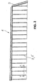
- a particularly advantageous embodiment of the cover layer 2 or 3 in the form of a module-like panel 30 shows the Fig. 8 ,
- the panel 30 has two specially shaped, mutually compatible outer edges 12, 14, which when joining two adjacent panels 30, a snap or click connection 20 (see. Fig. 9 ) form.
- On the panel 30 in addition inwardly facing reinforcing ribs 36 are provided.
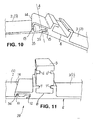
- the panels 30 are in a mutually inclined position (see. Fig. 10 ), in which the one, inwardly offset outer edge 12 of a panel is inserted into a groove 15 of the other panel such that a rotational movement about an axis of rotation A can take place.
- the axis of rotation A is formed by an outer, opposite the outer edge 14 set back longitudinal edge 33.
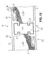
- the Fig. 12 shows the spacer profile 5, arranged between two successive holding profiles 8, 8 ', which are each made in one piece with a panel 30.
- the panels 30 of a cover layer 2 and 3 are connected to each other via a click connection 20.
- the cover layers 2 and 3 form cavities 38, in which the plate-shaped insulation layers 1 (shown in part) are housed.
- the outer cover layer 3 is composed of several panels 30, whereas the opposite, inner cover layer 2 on its - in the assembled state - the trough bottom 10 facing inside 37 is completely seamless and smooth.
- the click connection 20 connects panels 30 of the outer cover layer 3 with each other.
- the inner, elongated cover layer 2 has only the spaced-apart, C-shaped retaining profiles 8 ', which lie opposite the corresponding retaining profiles 8 on the outer cover layer 3.
- cover layers 2, 3 it is also important here for the cover layers 2, 3 to be thermally decoupled from one another in order to be able to achieve the required thermal resistance value (R value) of ⁇ 1.65 m 2 K / W.
- the invention is not limited to the illustrated embodiments. Further embodiments are possible without departing from the basic idea. For example, it is also possible to decouple the tailgate 9 thermally and to insulate so that as little as possible heat losses occur.
- the transport tray 100 can also be thermally covered, for example, by a loss of energy as much as possible retardant roll tarpaulin, Roman shade or a segmented top.
- the sensitive cargo is circumferentially isolated and leads to safe transport on long hauls when the desired temperature. This results in very good insulation values, which correspond to the official regulations.
- the vehicles still have a high payload due to the insulation according to the invention.
- the insulation is durable and rot-proof.
Landscapes
- Engineering & Computer Science (AREA)
- Transportation (AREA)
- Mechanical Engineering (AREA)
- Chemical & Material Sciences (AREA)
- Combustion & Propulsion (AREA)
- Thermal Insulation (AREA)
- Laying Of Electric Cables Or Lines Outside (AREA)
- Packages (AREA)
Applications Claiming Priority (2)
| Application Number | Priority Date | Filing Date | Title |
|---|---|---|---|
| DE202014101605.8U DE202014101605U1 (de) | 2014-04-04 | 2014-04-04 | Thermisch entkoppelte Muldenwand |
| DE202014103190.1U DE202014103190U1 (de) | 2014-04-04 | 2014-07-11 | Thermisch entkoppelte Mulde |
Publications (2)
| Publication Number | Publication Date |
|---|---|
| EP2927102A2 true EP2927102A2 (fr) | 2015-10-07 |
| EP2927102A3 EP2927102A3 (fr) | 2016-01-13 |
Family
ID=50778671
Family Applications (1)
| Application Number | Title | Priority Date | Filing Date |
|---|---|---|---|
| EP15000881.1A Withdrawn EP2927102A3 (fr) | 2014-04-04 | 2015-03-25 | Auge de transport destinée au transport de matériaux chauds |
Country Status (2)
| Country | Link |
|---|---|
| EP (1) | EP2927102A3 (fr) |
| DE (2) | DE202014101605U1 (fr) |
Cited By (1)
| Publication number | Priority date | Publication date | Assignee | Title |
|---|---|---|---|---|
| EP3527468A1 (fr) * | 2018-02-15 | 2019-08-21 | Fahrzeugwerk Bernard Krone GmbH & Co. KG | Caisse pour véhicules utilitaires |
Family Cites Families (3)
| Publication number | Priority date | Publication date | Assignee | Title |
|---|---|---|---|---|
| US1040459A (en) * | 1908-06-12 | 1912-10-08 | William Frederick Taylor | Regenerative furnace. |
| GB2067522A (en) * | 1980-01-19 | 1981-07-30 | Tarmac Roadstone Holdings Ltd | Heated transport containers |
| DE58907180D1 (de) | 1988-12-23 | 1994-04-14 | Alusuisse Lonza Services Ag | Isolierte Mulde für Schienen- und/oder Strassenfahrzeuge. |
-
2014
- 2014-04-04 DE DE202014101605.8U patent/DE202014101605U1/de not_active Expired - Lifetime
- 2014-07-11 DE DE202014103190.1U patent/DE202014103190U1/de not_active Expired - Lifetime
-
2015
- 2015-03-25 EP EP15000881.1A patent/EP2927102A3/fr not_active Withdrawn
Cited By (1)
| Publication number | Priority date | Publication date | Assignee | Title |
|---|---|---|---|---|
| EP3527468A1 (fr) * | 2018-02-15 | 2019-08-21 | Fahrzeugwerk Bernard Krone GmbH & Co. KG | Caisse pour véhicules utilitaires |
Also Published As
| Publication number | Publication date |
|---|---|
| EP2927102A3 (fr) | 2016-01-13 |
| DE202014103190U1 (de) | 2014-07-23 |
| DE202014101605U1 (de) | 2014-05-06 |
Similar Documents
| Publication | Publication Date | Title |
|---|---|---|
| DE2231763A1 (de) | Leitplanke | |
| DE102013105987B4 (de) | Fahrzeugaufbau | |
| EP2452896B1 (fr) | Structure de sol à isolation thermique, sol pour une cale de cargaison, méthode de fabrication d'une structure de sol à isolation thermique | |
| EP2228511B1 (fr) | Profilé de seuil en plusieurs parties pour une porte oscillo-battante | |
| EP2666949B1 (fr) | Battant de fenêtre ou de porte | |
| EP1319584B1 (fr) | Benne basculante pour un véhicule | |
| EP2116461B1 (fr) | Structure de coffre pour un véhicule, comme un poids lourd, une remorque ou un train routier | |
| DE202014007735U1 (de) | Verbessertes Industriezelt | |
| DE102010064034A1 (de) | Isolierstab für Verbundprofil von Bauelementen | |
| EP2116453B1 (fr) | Traverse pour un élément de plancher d'un véhicule, comme un poids lourd, une semi-remorque ou une remorque, et élément de plancher doté d'une telle traverse | |
| EP3090926B1 (fr) | Structure de plancher d'une carrosserie de véhicule utilitaire | |
| EP2927102A2 (fr) | Auge de transport destinée au transport de matériaux chauds | |
| EP1405780B1 (fr) | Véhicule à parois latérales coulissantes, pour le transport par chemin de fer de produits sensibles à la température | |
| EP0109093A1 (fr) | Dispositif de renforcement pour cabines, en particulier superstructures de camions | |
| EP2995929B1 (fr) | Chambre de test climatisée | |
| DE1575090A1 (de) | Aus waermeisolierenden Platten zusammengesetzte Baueinheit sowie Verfahren zur Herstellung,zum Verbinden und Verstaerken derartiger Platten | |
| DE102021108665A1 (de) | Verbundprofil für einen Kofferaufbau für ein Nutzfahrzeug sowie Kofferaufbau für ein Nutzfahrzeug | |
| EP3388317B1 (fr) | Construction de véhicule frigorifique | |
| DE102016109636A1 (de) | Paneel und Ladungssicherungsschiene zur Sicherung von Ladungssicherungsmitteln | |
| DE202010005698U1 (de) | Dämmriegel, Dämmprofil und Dämmsystem | |
| EP2363337B1 (fr) | Structure pour un véhicule de transport et véhicule de transport frigorifique doté d'une telle structure | |
| EP3210861B1 (fr) | Panneau et assemblage d'un vehicule utilitaire comprenant un dispositif d'aeration | |
| EP1143215B1 (fr) | Paroi double calorifugée | |
| EP3695996B1 (fr) | Caisse à verrouillage en court-circuit | |
| EP2116457A1 (fr) | Elément de sol et liaison entre un élément de sol et une paroi latérale pour un véhicule, comme un poids lourd, un semi-remorque ou une remorque |
Legal Events
| Date | Code | Title | Description |
|---|---|---|---|
| PUAI | Public reference made under article 153(3) epc to a published international application that has entered the european phase |
Free format text: ORIGINAL CODE: 0009012 |
|
| AK | Designated contracting states |
Kind code of ref document: A2 Designated state(s): AL AT BE BG CH CY CZ DE DK EE ES FI FR GB GR HR HU IE IS IT LI LT LU LV MC MK MT NL NO PL PT RO RS SE SI SK SM TR |
|
| AX | Request for extension of the european patent |
Extension state: BA ME |
|
| PUAL | Search report despatched |
Free format text: ORIGINAL CODE: 0009013 |
|
| AK | Designated contracting states |
Kind code of ref document: A3 Designated state(s): AL AT BE BG CH CY CZ DE DK EE ES FI FR GB GR HR HU IE IS IT LI LT LU LV MC MK MT NL NO PL PT RO RS SE SI SK SM TR |
|
| AX | Request for extension of the european patent |
Extension state: BA ME |
|
| RIC1 | Information provided on ipc code assigned before grant |
Ipc: B62D 33/04 20060101AFI20151204BHEP |
|
| STAA | Information on the status of an ep patent application or granted ep patent |
Free format text: STATUS: THE APPLICATION IS DEEMED TO BE WITHDRAWN |
|
| 18D | Application deemed to be withdrawn |
Effective date: 20160714 |