EP2116461B1 - Structure de coffre pour un véhicule, comme un poids lourd, une remorque ou un train routier - Google Patents
Structure de coffre pour un véhicule, comme un poids lourd, une remorque ou un train routier Download PDFInfo
- Publication number
- EP2116461B1 EP2116461B1 EP20080103913 EP08103913A EP2116461B1 EP 2116461 B1 EP2116461 B1 EP 2116461B1 EP 20080103913 EP20080103913 EP 20080103913 EP 08103913 A EP08103913 A EP 08103913A EP 2116461 B1 EP2116461 B1 EP 2116461B1
- Authority
- EP
- European Patent Office
- Prior art keywords
- side wall
- box body
- wall elements
- roof
- elements
- Prior art date
- Legal status (The legal status is an assumption and is not a legal conclusion. Google has not performed a legal analysis and makes no representation as to the accuracy of the status listed.)
- Active
Links
- 238000005304 joining Methods 0.000 claims description 33
- 239000000463 material Substances 0.000 claims description 22
- 239000006260 foam Substances 0.000 claims description 16
- 238000000465 moulding Methods 0.000 claims description 7
- 238000010276 construction Methods 0.000 claims description 6
- 239000002184 metal Substances 0.000 claims description 2
- 239000000565 sealant Substances 0.000 claims description 2
- 230000003116 impacting effect Effects 0.000 claims 2
- 239000010410 layer Substances 0.000 description 13
- 238000004519 manufacturing process Methods 0.000 description 11
- 238000007373 indentation Methods 0.000 description 4
- 238000001816 cooling Methods 0.000 description 2
- 238000000034 method Methods 0.000 description 2
- 239000007787 solid Substances 0.000 description 2
- 229910000831 Steel Inorganic materials 0.000 description 1
- 239000012790 adhesive layer Substances 0.000 description 1
- 230000015572 biosynthetic process Effects 0.000 description 1
- 239000002131 composite material Substances 0.000 description 1
- 150000001875 compounds Chemical class 0.000 description 1
- 238000009833 condensation Methods 0.000 description 1
- 230000005494 condensation Effects 0.000 description 1
- 238000002788 crimping Methods 0.000 description 1
- 230000001419 dependent effect Effects 0.000 description 1
- 238000005187 foaming Methods 0.000 description 1
- 230000005484 gravity Effects 0.000 description 1
- 238000009413 insulation Methods 0.000 description 1
- 239000007769 metal material Substances 0.000 description 1
- 230000035515 penetration Effects 0.000 description 1
- 238000003825 pressing Methods 0.000 description 1
- 238000005096 rolling process Methods 0.000 description 1
- 238000007789 sealing Methods 0.000 description 1
- 238000004826 seaming Methods 0.000 description 1
- 239000010959 steel Substances 0.000 description 1
- 230000007704 transition Effects 0.000 description 1
Images


Classifications
-
- B—PERFORMING OPERATIONS; TRANSPORTING
- B62—LAND VEHICLES FOR TRAVELLING OTHERWISE THAN ON RAILS
- B62D—MOTOR VEHICLES; TRAILERS
- B62D29/00—Superstructures, understructures, or sub-units thereof, characterised by the material thereof
- B62D29/04—Superstructures, understructures, or sub-units thereof, characterised by the material thereof predominantly of synthetic material
- B62D29/043—Superstructures
- B62D29/045—Van bodies composed of substantially rectangular panels
-
- B—PERFORMING OPERATIONS; TRANSPORTING
- B62—LAND VEHICLES FOR TRAVELLING OTHERWISE THAN ON RAILS
- B62D—MOTOR VEHICLES; TRAILERS
- B62D33/00—Superstructures for load-carrying vehicles
- B62D33/04—Enclosed load compartments ; Frameworks for movable panels, tarpaulins or side curtains
- B62D33/044—Enclosed load compartments ; Frameworks for movable panels, tarpaulins or side curtains built up with profiles of constant elongated shape, e.g. extruded, mechanically interconnected by coupling members, e.g. by clamping, riveting or bolting
-
- B—PERFORMING OPERATIONS; TRANSPORTING
- B62—LAND VEHICLES FOR TRAVELLING OTHERWISE THAN ON RAILS
- B62D—MOTOR VEHICLES; TRAILERS
- B62D33/00—Superstructures for load-carrying vehicles
- B62D33/04—Enclosed load compartments ; Frameworks for movable panels, tarpaulins or side curtains
- B62D33/046—Enclosed load compartments ; Frameworks for movable panels, tarpaulins or side curtains built up with flat self-supporting panels; Fixed connections between panels
Definitions
- the invention relates to a box body for a vehicle, such as a truck, trailer or semi-trailer, which is composed of a bottom element, side wall elements, of which a side wall element is arranged on the one and the other side wall element on the other longitudinal side of the bottom element, and a roof element.
- box bodies are used in particular for refrigerated vehicles, with which perishable goods are transported.
- the wall, roof and floor elements of the box body are therefore usually constructed as a sandwich construction consisting of two outer layers of sheet steel and a filled between the outer layers of foam filling.
- the metallic outer layers protect the foam filling against damage, while the foam filling ensures the heat insulation and sufficient strength of the sandwich composite.
- luggage structures of the type in question Regardless of the intended use of luggage structures of the type in question is required that they have a low weight and can be produced inexpensively. Therefore, it is endeavored to connect the individual elements of such a box body as simply as possible. At the same time the box bodies should have such a high dimensional stability that They also safely protect the load being transported under unfavorable operating conditions.
- connection plates are preformed as separate components and then glued to the outside of the preassembled wall elements. Subsequently, the terminal plates are crimped with their associated edge portions so that a solid positive connection is made. By regularly set welds the seam connection is additionally secured.
- the invention was based on the object to provide a box body for a vehicle that can be produced with minimal production costs.
- An inventive box body for a vehicle such as a truck, trailer or semi-trailer is conventionally composed of a bottom member, side wall members, one of which is disposed on one of the longitudinal sides of the bottom member and another on the end side of the bottom member, and a roof member which is supported by the sidewall elements.
- a joining zone is now formed at least between the side wall elements forming the longitudinal side walls of the box body and the bottom element and the respective side wall element abutting one another and connected to one another by a folding connection arranged on the outside of the box body.
- a folding connection arranged on the outside of the box body.
- the box body in the region of the joining zones each have a extending over the respective joining zone material recess, so that within the envelope of Kofferaubaus a running along the roof element first space in which the respective rabbet joint between the roof element and the Side wall elements is arranged, and a second space extending along the bottom element are formed, in which the respective rabbet connection between the bottom element and the longitudinal wall elements or the end wall element is arranged.
- the seam connections are each formed from two of the interconnected elements projecting connecting plates. This has the advantage that sheet metal materials can be used for the seam connection, which are optimally deformable and prefabricated as separate moldings are placed on the outside of the interconnected elements.
- the side wall elements are constructed as sandwich structures, which are formed by a solid outer layer, a fixed inner layer and a filled between the classifiedund the inner layer foam filling.
- the presses required for the production of such sandwich constructions can be made particularly simple and therefore inexpensive as a result of the inventive design of the side wall elements.
- the pressing surfaces coming into contact with the side wall element can be continuously flat, since the depth of the indentation in which the respective connection plate lies is at least equal to the smallest thickness of the connection plate lying in it. In this way, it is obvious that the free surface of the connecting plates is aligned in each case largely flush with the surface of the side wall elements.
- the side wall element with the roof and the floor element which forms the towing vehicle facing end wall of the box body.
- the joining and the folding zones are arranged within the envelope of the box body so that each one of the one longitudinal side to the other longitudinal side to the roof element and the floor element encircling space forms, in which the present invention used Falztagenen are made, without that they protrude over one of the side walls, the roof or the bottom of the box body.
- box bodies according to the invention will typically have a cuboid basic shape, so that the envelope of a box structure according to the invention forms a parallelepiped.
- the inventively provided seaming are positioned in this case.
- a particularly stable and practical embodiment of the invention is characterized in that the side wall elements are each supported on an edge region of the bottom element and that the roof element rests on the side wall elements.
- This type of side walls on the bottom element and the roof element on the side wall elements results in combination with the arranged on the outside of the box body folds a particularly high dimensional stability, since the Falztagenen need not absorb loads, but only ensure that the side wall parts and the roof element or the bottom element are held together in a direction transverse to the effective direction of gravity direction.
- each interconnected elements can be supported by the fact that at least to the roof-side longitudinal edges of the longitudinal sides of the box body associated side wall elements and their associated edges of the roof element each paragraphs are formed which are formed corresponding to each other, that the roof element is held in the assembled state positively between the respective side wall elements and supported on them.
- the side wall elements assigned to the longitudinal sides can be provided with shoulders over which the respective side wall elements each sit on a correspondingly shaped shoulder of the floor element.
- the material recess may be formed by a respective chamfer, which extends in each case along the mutually associated edges of floor element, side wall elements and roof element.
- connection plates required for the FalzMISen are already connected in the production of sidewall, roof or floor elements with one of the outer layers and only then following the foam filling is given in the space bounded by the outer layers. Characteristic of this type of production is then that in the finished side wall or roof elements, the terminal plates are wetted with foam foam filling.
- connection of the side wall elements with the bottom and roof element is characterized in that the side wall elements each have a flat outer surface and the associated Falzharmen each have a leg whose outer surface is in the extension of extending respective outer surface of the respective side wall element.
- Ingress of moisture into the seam connections can be prevented by filling the space remaining between the respective seam connection and the roof element or between the respective seam connection and the floor element with a sealant.
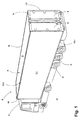
- designed as a refrigerated transporter S consists in on a known type of a tractor Z and a semi-trailer A.
- the semitrailer A comprises a box body K, which is mounted on a chassis chassis C.
- the box body K isolates the interior I surrounded by it against the heat of the surroundings U.
- the box body K is composed of a bottom element B, a roof element D and the side wall elements L1, L2 and W.
- the side wall elements L1, L2, W the side wall elements L1, L2, the longitudinal side walls and the side wall element W, the end wall of the box body K.
- a cooling unit M may be mounted, the interior I of the box body K with cooled air provided.
- the bottom element B in addition to the chassis chassis C and a landing gear E is connected, which serves to support the semi-trailer A in the decoupled from the tractor Z state.
- the box body K comprises a rear wall R, in which the doors T are provided, via which the interior I of the box body K is loaded and unloaded.
- the rear wall in principle, it would also be conceivable to form the rear wall as a side wall element, and this in the manner described here for side wall elements L1, L2 and W with the bottom element B or to connect the roof element D.
- the rear wall R should be considered as a separate part, which is manufactured and arranged in a different manner.
- both the side wall elements L1, L2 forming the two longitudinal side walls and the side wall element W forming the end wall are connected to the roof element D and the bottom element B in the manner according to the invention ,
- the end wall W in a different way to the main body, which is formed from the interconnected in accordance with the invention roof element D, bottom element B and side wall elements L1, L2. This may be necessary, for example, if length tolerances of the individual components meeting there have to be compensated in the region of the end wall.
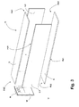
- a joining zone Fb1, Fb2, Fb3 is respectively formed between the side wall elements L1, L2, W and the bottom element B, in which the bottom element B and the respective side wall element L1, L2, W abut each other.
- a further joining zone Fd1, Fd2, Fd3 is present between the side wall elements L1, L2, W and the roof element D, in which the roof element D and the respective side wall element L1, L2, W abut each other.
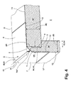
- the material recess is formed in each case by the fact that the edge region D of the respective joining zone Fd1, Fd2, Fd3 is missing on the roof element D by a chamfer running at an angle of approximately 45 ° there G is provided. Equally, the edge region of the respective side wall element L1, L2, W assigned to the respective joining zone Fd1, Pd2, Fd3 is also missing, since this edge region is also bevelled at an angle of approximately 45 °.
- the bevels G of the respective side wall element L1, L2, W and the roof element D thus limit the material side of the material recess Md1, in which the respective fold connection Vd1, Vd2, Vd3 is arranged.
- the bevels G are formed at the free ends of edge portions 1,2, which are present at the mutually associated edges of the roof element D and the side wall elements L1, L2, W.
- the depth of t3, t4 and height h3, h4 are dimensioned so that the thickness dR of all edge sections 1,2 regardless of the thickness dD of the respective roof element D and the thickness dS of the respective side element is the same.
- An air gap-free positive fit of the roof element D on the side members L1, L2, W results from the fact that the depth t3 of the paragraph 3 of the respective side wall element L1, L2, W equal to the height h4 of the paragraph 4 of the roof element D and the depth t4 of Paragraph 4 of the roof element is equal to the height h3 of paragraph 3 of the respective side wall element L1, L2, W is.
- the positive fit of the roof element D on the side wall elements L1, L2, W is thereby supported, that the abutting surfaces, at which the edge portions 1,2 abut each other with their free end faces, are chamfered corresponding to each other at an angle of 45 °.
- the side wall elements L1, L2, W are supported on their associated edge region of the bottom element B.
- the side wall elements L1, L2 associated with the longitudinal sides of the floor element B each stand on a longitudinal profile 5 extending over the length of the floor element B.
- a shoulder is formed on the inside of the respective side wall elements L1, L2, the shape of which is selected so that the respective side wall element L1, L2 sits form-fitting tightly on the respective longitudinal profile 5 and covers it laterally relative to the environment.
- the material recess Mb1 in the region of the joining zones Fb1, Fb2, Fb3 is formed by the fact that the lower outer longitudinal edge region of the side wall elements L1, L2 is chamfered at an angle of 45 °, so that there is an obliquely extending in the direction of the underside US of the bottom element B. Surface is formed. This surface goes into a corresponding oblique section of the respective Longitudinal profile 5 on, wherein the thickness of the longitudinal profiles 5 corresponds to about half the thickness dS of the side wall elements L1, L2. Accordingly, even in the area of the material recess Mb1, missing volumes of the bottom element B and the respective side wall element L1, L2 contribute in equal parts to the space present in the region of the material recess Mb1.
- connection plates 6, 7, 8, 9 which is fastened to the respective side wall element L1, L2, W or the roof element D and the bottom element B.
- the connection plates 6, 7, 8, 9 have already been fitted to the relevant element L1, L2, W, B, D during the production of the side wall elements L1, L2, W, the roof element D and the bottom element B.
- the respective connecting plate 6, 7, 9 in the respective edge area is connected to the outside of the outer layer 10, 11 of the respective side wall element L1 assigned to the surroundings U. , L2, W or roof element D glued.
- a recess 12,13,14 was already formed in the respective edge region of the respective outer layer 10,11, the depth of which was dimensioned taking into account the thickness of the respective connection plate 6,7,9 and the required adhesive layer so that the exposed outer surface of the connection plate 6,7,9 is aligned substantially flush with the planar outer surface of the respective side wall element L1, L2, W or roof element D.
- the connecting plate 8 is placed only on the flat bottom US and there also glued.
- the connecting plates 6, 7, 8, 9, 9 are each arranged such that they project freely beyond the respective side wall element L 1, L 2, W or the bottom element B and the roof element D with their one edge region.
- the bottom element B and the roof element D assigned and bottom element B arranged connecting elements 6,8 each have an angled portion which fits tightly against the inclined surface G of the edge portion 2 (connecting element 6) or the inclined surface of the longitudinal profile 5 (connecting element 8). From the bent portion of the connecting elements 6,8 goes from another section which extends substantially parallel to the outer surface of the roof element D (connecting element 6) or to the underside US of the bottom element B (connecting element 8). This section in turn passes in a projecting at a right angle from him in the direction of the environment U final section.
- the connecting elements 7, 9 which are assigned to the side wall elements L1, L2, W likewise have a first, opposite their in the indentation of the side wall element L1, L2, W lying portion which bears against the respective material recess Md1, Mb1 bounding inclined surface of the respective side wall element L1, L2, W.
- a second section which is directed substantially perpendicular to the outer surface of the side wall element L1, L2, W in the direction of the environment U.
- This section is followed by a closing section, which is laid by means of a flanging or rolling machine, not shown here, lying flat around the respective end section of the respective associated connection element 6,8.
- the lengths of the fold connections Vd1, Vd2, Vd3, Vb1, Vb2, Vb3 forming sections of the connecting plates are chosen so that the hinge connections Vd1, Vd2, Vd3, Vb1, Vb2, Vb3 do not extend overall from the envelope H of the box body K.
- the fold connections Vd1, Vd2, Vd3, Vb1, Vb2, Vb3 each have a leg 15, 16, the outside of which extends substantially flush with the outside of the respective side element L1, L2, W.
- the space remaining between the respective legs 15, 16 and the roof element D or base element B can be filled with a sealing compound in order to prevent the penetration of moisture into the respective hinge connection Vd1, Vd2, Vd3, Vb1, Vb2, Vb3.
Landscapes
- Engineering & Computer Science (AREA)
- Chemical & Material Sciences (AREA)
- Combustion & Propulsion (AREA)
- Transportation (AREA)
- Mechanical Engineering (AREA)
- Architecture (AREA)
- Structural Engineering (AREA)
- Body Structure For Vehicles (AREA)
Claims (15)
- Structure de coffre pour un véhicule automobile, comme un camion, une remorque ou une semi-remorque (A), aveca) un élément de plancher (B),b) des éléments de parois latérales (L1, L2), un élément de paroi latérale (L1) étant disposé sur un côté longitudinal et l'autre élément de paroi latérale (L2) sur l'autre côté longitudinal de l'élément de plancher (B),c) un élément de toit (D),d) sachant que, entre les éléments de parois latérales (L1, L2) et l'élément de plancher (B), il existe une zone de jonction (Fb1 à Fb3), dans laquelle l'élément de plancher (B) et l'élément de paroi latérale (L1, L2) respectif portant l'un contre l'autre et sont reliés ensemble par un agrafage (Vb1 à Vb3), qui est disposé sur le côté extérieur de la structure de coffre (K), et que, entre les éléments de parois latérales (L1, L2) et l'élément de toit (D), il existe une autre zone de jonction (Fd1 à Fd3), dans laquelle l'élément de toit (D) et l'élément de paroi latérale (L1, L2) respectif porte l'un contre l'autre et sont également reliés ensemble par un agrafage (Vd1 à Vd3), qui est disposé sur le côté extérieur de la structure de coffre (K)e) sachant que les agrafages (Vd1 à Vd3 ; Vb1 à Vb3) sont formés chacun par deux tôles de raccordement (6, 7, 8, 9) en saillie des deux éléments (éléments de parois latérales L1, L2 ; élément de plancher B et élément de toit D), y reliés ensemble, qui sont rapportées sur le côté extérieur des éléments (L1, L2, W, B, D) reliés ensemble,
caractérisée en ce quef) la structure de coffre (K) est dotée, dans chaque région des zones de jonction (Fd1 à Fd3 ; Fb1 à Fb3), d'un évidement (Md1; Mb1), qui s'étend sur la zone de jonction (Fd1 à Fd3 ; Fb1 à Fb3) concernée, de sorte que, à l'intérieur de l'extrémité de l'enveloppe (H) parallélépipédique de la structure de coffre (K), il existe une première chambre, s'étendant le long de l'élément de toit (D), dans laquelle est agencé l'agrafage (Vd1 à Vd3) entre l'élément de toit (D) et les éléments de parois latérales (L1, L2), et une deuxième chambre, s'étendant le long de l'élément de plancher (B), dans laquelle est agencé l'agrafage (Vb1 à Vb3) entre l'élément de plancher (B) et les éléments de parois latérales (L1, L2, W),g) au moins les éléments de parois latérales (L1, L2, W) sont dotés, dans chacune de leurs zones marginales associées aux zones de jonction (Fd1 à Fd3 ; Fb1 à Fb3), d'une pièce façonnée (12, 13, 14), s'étendant sur la zones de jonction (Fd1 à Fd3 ; Fb1 à Fb3), dans laquelle les tôles de raccordement (6, 7, 8, 9) sont placées avec leur zone recouvrant l'élément de paroi latérale (L1, L2, W) concerné, eth) la profondeur de chaque pièce façonnée (12, 13, 14) est au moins égale à la plus petite épaisseur de la tôle de raccordement (6, 7, 8, 9) qu'elle contient. - Structure de coffre selon la revendication 1, caractérisée en ce que fait partie des éléments de parois latérales, en plus des éléments de parois latérales (L1, L2) associés aux côtés longitudinaux de la structure de coffre (K), un élément de paroi latérale (W), qui est agencé sur le côté frontal de la structure de coffre (K).
- Structure de coffre selon l'une des revendications précédentes, caractérisée en ce que l'extrémité de l'enveloppe (H) de la structure de coffre (K) forme un parallélépipède.
- Structure de coffre selon l'une des revendications précédentes, caractérisée en ce que les éléments de parois latérales (L1, L2, W) prennent chacune appui sur une zone marginale de l'élément de plancher (B) et que l'élément de toit (D) est posé sur les éléments de parois latérales (L1, L2, W).
- Structure de coffre selon l'une des revendications précédentes, caractérisée en ce que, tout au moins sur les bords longitudinaux côte toit des éléments de parois latérales (L1, L2) associés aux côtés longitudinaux de la structure de coffre (K) et sur les bords de l'élément de toit (D), qui leur sont associés, sont respectivement formés des talons (1, 2) qui correspondent les uns aux autres de sorte que l'élément de toit (D), à l'état fini monté, est maintenu, par emboîtement, entre les éléments de parois latérales (L1, L2) concernés et prend appui sur eux.
- Structure de coffre selon l'une des revendications précédentes, caractérisée en ce que, sur les bords longitudinaux, côté élément de plancher (B), des éléments de parois latérales (L1, L2, W) associés aux côtés longitudinaux, sont formés des talons par l'intermédiaire desquels les éléments de parois latérales (L1, L2, W) concernés sont posés sur un talon de forme correspondante de l'élément de plancher (B).
- Structure de coffre selon l'une des revendications précédentes, caractérisée en ce que les évidements (Md1, Mb1) sont formés chacun par un chanfrein (G), qui s'étend le long des bords de l'élément de plancher (B), des éléments de parois latérales (L1, L2, W) et de l'élément de toit (D) associés.
- Structure de coffre selon l'une des revendications précédentes, caractérisée en ce que, dans la région des évidements (Md1, Mb1) de la matière enlevée manque, d'une part à l'un et d'autre part à l'autre des éléments (élément de plancher (B), éléments de parois latérales (L1, L2, W) et / ou élément de toit (D)) portant les uns contre les autres dans la zone de jonction.
- Structure de coffre selon la revendication 8 caractérisée en ce que, dans la région de l'évidement, de la matière enlevée manque, en partie égales aux éléments (élément de plancher (B), éléments de parois latérales (L1, L2, W) et / ou élément de toit (D)) portant les uns contre les autres dans la zone de jonction.
- Structure de coffre selon l'une des revendications précédentes, caractérisée en ce que l'élément de toit (D) est doté dans chacune de ses zones de bord respectivement associées aux zones de jonction (Fd1 à Fd3), d'une partie façonnée en creux (12), qui s'étend sur la zone de jonction (Fd1 à Fd3) concernée, dans laquelle la tôle de raccordement (6) respectivement associée à la zone de jonction (Fd1 à Fd3) concernée est logée avec sa zone recouvrant l'élément de toit (D).
- Structure de coffre selon la revendication 10, caractérisée en ce que la profondeur de chaque partie façonnée en creux (12, 13, 14) est au moins égale à l'épaisseur de la tôle de raccordement (6, 7, 8, 9) qu'elle contient.
- Structure de coffre selon l'une des revendications précédentes, caractérisée en ce que les éléments de parois latérales (L1, L2, W) et l'élément de toit (D) sont réalisés en tant que constructions sandwichs avec deux couches extérieures (10, 11), qui consistent en tôle métalliques, et un remplissage de mousse (SF) entre les deux couches extérieures.
- Structure de coffre selon l'une des revendications précédentes, caractérisée en ce qu'au moins les tôles de raccordement (6, 7, 9) associées aux éléments de parois latérales (L1, L2, W) et à l'élément de toit (D) sont humectées de mousse de la charge de mousse (SF).
- Structure de coffre selon l'une des revendications précédentes, caractérisée en ce que les éléments de parois latérales (L1, L2, W) sont dotés chacun d'une surface extérieure plane et que les agrafages, qui leur sont associées, sont dotés chacun d'une aile (15, 16), dont la surface extérieure s'étend en prolongement de la surface extérieure respective de chaque élément de paroi latérale (L1, L2, W).
- Structure de coffre selon l'une des revendications précédentes, caractérisée en ce que l'espace demeurant entre chaque agrafage et l'élément de toit (D) ou entre chaque agrafage et l'élément de plancher (B) est rempli avec une matière d'étanchéité.
Priority Applications (2)
| Application Number | Priority Date | Filing Date | Title |
|---|---|---|---|
| EP20080103913 EP2116461B1 (fr) | 2008-05-09 | 2008-05-09 | Structure de coffre pour un véhicule, comme un poids lourd, une remorque ou un train routier |
| DK08103913T DK2116461T3 (da) | 2008-05-09 | 2008-05-09 | Kassekonstruktion til et fartøj, såsom en lastvogn, anhænger eller sættevogn |
Applications Claiming Priority (1)
| Application Number | Priority Date | Filing Date | Title |
|---|---|---|---|
| EP20080103913 EP2116461B1 (fr) | 2008-05-09 | 2008-05-09 | Structure de coffre pour un véhicule, comme un poids lourd, une remorque ou un train routier |
Publications (2)
| Publication Number | Publication Date |
|---|---|
| EP2116461A1 EP2116461A1 (fr) | 2009-11-11 |
| EP2116461B1 true EP2116461B1 (fr) | 2013-03-20 |
Family
ID=39758850
Family Applications (1)
| Application Number | Title | Priority Date | Filing Date |
|---|---|---|---|
| EP20080103913 Active EP2116461B1 (fr) | 2008-05-09 | 2008-05-09 | Structure de coffre pour un véhicule, comme un poids lourd, une remorque ou un train routier |
Country Status (2)
| Country | Link |
|---|---|
| EP (1) | EP2116461B1 (fr) |
| DK (1) | DK2116461T3 (fr) |
Cited By (4)
| Publication number | Priority date | Publication date | Assignee | Title |
|---|---|---|---|---|
| EP2799264A1 (fr) | 2013-04-29 | 2014-11-05 | Schmitz Cargobull AG | Véhicule utilitaire pour le transport de marchandises de transport à température contrôlée et procédé de fonctionnement d'une machine frigorifique prévue pour un tel véhicule utilitaire |
| DE202014105268U1 (de) | 2014-11-03 | 2014-11-19 | Schmitz Cargobull Ag | Vorrichtung für den hängenden Transport von Nahrungsmitteln und mit einer solchen Vorrichtung ausgestattetes Nutzfahrzeug |
| DE102015104817A1 (de) | 2015-03-27 | 2016-09-29 | Schmitz Cargobull Ag | Nutzfahrzeug für den Transport von temperaturempfindlichen Gütern |
| DE102016113587A1 (de) | 2016-07-22 | 2018-01-25 | Schmitz Cargobull Ag | Flächenelement und Aufbau für ein Nutzfahrzeug |
Families Citing this family (2)
| Publication number | Priority date | Publication date | Assignee | Title |
|---|---|---|---|---|
| US9676549B2 (en) | 2014-12-02 | 2017-06-13 | Fontaine Commercial Trailer, Inc. | Floor assembly for transportable refrigerated container |
| CN114194302A (zh) * | 2021-12-28 | 2022-03-18 | 中集车辆太字节汽车车厢科技(镇江)有限公司 | 一种车厢底部的防水连接结构 |
Family Cites Families (4)
| Publication number | Priority date | Publication date | Assignee | Title |
|---|---|---|---|---|
| US4531278A (en) * | 1982-12-13 | 1985-07-30 | Hackney Brothers Body Company, Inc. | Method of forming an insulated body for a vehicle |
| DE9014345U1 (de) * | 1990-10-16 | 1991-11-14 | Goldbecker Form GmbH, 4803 Steinhagen | Kastenaufbau, insbesondere für Radfahrzeuge |
| DE10103077B4 (de) | 2001-01-24 | 2008-02-14 | Schmitz Cargobull Ag | Eckabschlussanordnung für einen Koffer-Fahrzeugaufbau |
| FR2845062B1 (fr) * | 2002-09-30 | 2004-12-17 | Andre Michel Robert Morin | Dispositif d'assemblage de panneaux de carrosserie modulaire |
-
2008
- 2008-05-09 DK DK08103913T patent/DK2116461T3/da active
- 2008-05-09 EP EP20080103913 patent/EP2116461B1/fr active Active
Cited By (4)
| Publication number | Priority date | Publication date | Assignee | Title |
|---|---|---|---|---|
| EP2799264A1 (fr) | 2013-04-29 | 2014-11-05 | Schmitz Cargobull AG | Véhicule utilitaire pour le transport de marchandises de transport à température contrôlée et procédé de fonctionnement d'une machine frigorifique prévue pour un tel véhicule utilitaire |
| DE202014105268U1 (de) | 2014-11-03 | 2014-11-19 | Schmitz Cargobull Ag | Vorrichtung für den hängenden Transport von Nahrungsmitteln und mit einer solchen Vorrichtung ausgestattetes Nutzfahrzeug |
| DE102015104817A1 (de) | 2015-03-27 | 2016-09-29 | Schmitz Cargobull Ag | Nutzfahrzeug für den Transport von temperaturempfindlichen Gütern |
| DE102016113587A1 (de) | 2016-07-22 | 2018-01-25 | Schmitz Cargobull Ag | Flächenelement und Aufbau für ein Nutzfahrzeug |
Also Published As
| Publication number | Publication date |
|---|---|
| EP2116461A1 (fr) | 2009-11-11 |
| DK2116461T3 (da) | 2013-06-10 |
Similar Documents
| Publication | Publication Date | Title |
|---|---|---|
| EP2116461B1 (fr) | Structure de coffre pour un véhicule, comme un poids lourd, une remorque ou un train routier | |
| EP2619063B1 (fr) | Caisse pour véhicule sur rails comportant un dispositif de fixation d'attelage et procédé de production correspondant | |
| DE102016121252B4 (de) | Batterieträger mit Eckverbinder sowie Verfahren zur Herstellung eines Batterieträgers | |
| EP2524856B1 (fr) | Création pour un véhicule utilitaire | |
| DE112015001402T5 (de) | Containervorrichtung mit Sandwich-Struktur | |
| WO2020038972A1 (fr) | Boîtier de batterie pour un véhicule entraîné par moteur électrique | |
| EP2881309B1 (fr) | Paroi latérale ou toit d'une structure de coffre d'un véhicule utilitaire | |
| EP3109123B1 (fr) | Vehicule comprenant un composant en forme de plaque pris en sandwich | |
| EP2116453B1 (fr) | Traverse pour un élément de plancher d'un véhicule, comme un poids lourd, une semi-remorque ou une remorque, et élément de plancher doté d'une telle traverse | |
| DE10161934A1 (de) | Kippmulde für ein Transportfahrzeug und Verfahren zur Herstellung von Kippmulden | |
| DE19643337A1 (de) | Schienenfahrzeug | |
| EP2524855B1 (fr) | Structure pour un véhicule utilitaire | |
| EP3210863A1 (fr) | Kit et procede de construction d'une structure de coffre pour un vehicule utilitaire et vehicule utilitaire | |
| EP2995929B1 (fr) | Chambre de test climatisée | |
| EP3388317B1 (fr) | Construction de véhicule frigorifique | |
| DE19538793C2 (de) | Modulelement | |
| EP1846280A1 (fr) | Capot de carrosserie pour automobiles, notamment pour autocars et similaires | |
| EP2116460B1 (fr) | Structure de coffre dotée d'un élément de liaison comprenant deux moitiés de liaison | |
| EP2116462B1 (fr) | Elément de paroi latérale et raccordement entre un élément de paroi latérale et un élément de plancher d'une structure de coffre pour un véhicule | |
| EP0735212A2 (fr) | Cadre pour panneaux de coffrage | |
| EP2103503A1 (fr) | Montage de coffre, composant de coffre et procédé de fabrication d'un montage de coffre pour un véhicule | |
| EP2524858A1 (fr) | Module individuel pour la formation d'un ensemble de coffre d'un véhicule utilitaire | |
| DE102015108731B4 (de) | Ladungssicherungssystem für einen Ladungsaufbau eines Nutzfahrzeugs | |
| EP3590798B1 (fr) | Coffre de véhicule utilitaire à portiques parallèles | |
| EP3266687B1 (fr) | Procede de reparation d'un element de surface d'une structure d'un vehicule automobile |
Legal Events
| Date | Code | Title | Description |
|---|---|---|---|
| PUAI | Public reference made under article 153(3) epc to a published international application that has entered the european phase |
Free format text: ORIGINAL CODE: 0009012 |
|
| AK | Designated contracting states |
Kind code of ref document: A1 Designated state(s): AT BE BG CH CY CZ DE DK EE ES FI FR GB GR HR HU IE IS IT LI LT LU LV MC MT NL NO PL PT RO SE SI SK TR |
|
| AX | Request for extension of the european patent |
Extension state: AL BA MK RS |
|
| 17P | Request for examination filed |
Effective date: 20100511 |
|
| AKX | Designation fees paid |
Designated state(s): AT BE BG CH CY CZ DE DK EE ES FI FR GB GR HR HU IE IS IT LI LT LU LV MC MT NL NO PL PT RO SE SI SK TR |
|
| GRAP | Despatch of communication of intention to grant a patent |
Free format text: ORIGINAL CODE: EPIDOSNIGR1 |
|
| GRAS | Grant fee paid |
Free format text: ORIGINAL CODE: EPIDOSNIGR3 |
|
| GRAA | (expected) grant |
Free format text: ORIGINAL CODE: 0009210 |
|
| AK | Designated contracting states |
Kind code of ref document: B1 Designated state(s): AT BE BG CH CY CZ DE DK EE ES FI FR GB GR HR HU IE IS IT LI LT LU LV MC MT NL NO PL PT RO SE SI SK TR |
|
| REG | Reference to a national code |
Ref country code: GB Ref legal event code: FG4D Free format text: NOT ENGLISH |
|
| REG | Reference to a national code |
Ref country code: CH Ref legal event code: EP |
|
| REG | Reference to a national code |
Ref country code: IE Ref legal event code: FG4D Free format text: LANGUAGE OF EP DOCUMENT: GERMAN |
|
| REG | Reference to a national code |
Ref country code: AT Ref legal event code: REF Ref document number: 601898 Country of ref document: AT Kind code of ref document: T Effective date: 20130415 |
|
| REG | Reference to a national code |
Ref country code: DE Ref legal event code: R096 Ref document number: 502008009515 Country of ref document: DE Effective date: 20130508 |
|
| REG | Reference to a national code |
Ref country code: DK Ref legal event code: T3 |
|
| REG | Reference to a national code |
Ref country code: NL Ref legal event code: T3 |
|
| PG25 | Lapsed in a contracting state [announced via postgrant information from national office to epo] |
Ref country code: ES Free format text: LAPSE BECAUSE OF FAILURE TO SUBMIT A TRANSLATION OF THE DESCRIPTION OR TO PAY THE FEE WITHIN THE PRESCRIBED TIME-LIMIT Effective date: 20130701 Ref country code: NO Free format text: LAPSE BECAUSE OF FAILURE TO SUBMIT A TRANSLATION OF THE DESCRIPTION OR TO PAY THE FEE WITHIN THE PRESCRIBED TIME-LIMIT Effective date: 20130620 Ref country code: SE Free format text: LAPSE BECAUSE OF FAILURE TO SUBMIT A TRANSLATION OF THE DESCRIPTION OR TO PAY THE FEE WITHIN THE PRESCRIBED TIME-LIMIT Effective date: 20130320 Ref country code: LT Free format text: LAPSE BECAUSE OF FAILURE TO SUBMIT A TRANSLATION OF THE DESCRIPTION OR TO PAY THE FEE WITHIN THE PRESCRIBED TIME-LIMIT Effective date: 20130320 Ref country code: BG Free format text: LAPSE BECAUSE OF FAILURE TO SUBMIT A TRANSLATION OF THE DESCRIPTION OR TO PAY THE FEE WITHIN THE PRESCRIBED TIME-LIMIT Effective date: 20130620 |
|
| REG | Reference to a national code |
Ref country code: LT Ref legal event code: MG4D |
|
| PG25 | Lapsed in a contracting state [announced via postgrant information from national office to epo] |
Ref country code: GR Free format text: LAPSE BECAUSE OF FAILURE TO SUBMIT A TRANSLATION OF THE DESCRIPTION OR TO PAY THE FEE WITHIN THE PRESCRIBED TIME-LIMIT Effective date: 20130621 Ref country code: FI Free format text: LAPSE BECAUSE OF FAILURE TO SUBMIT A TRANSLATION OF THE DESCRIPTION OR TO PAY THE FEE WITHIN THE PRESCRIBED TIME-LIMIT Effective date: 20130320 Ref country code: LV Free format text: LAPSE BECAUSE OF FAILURE TO SUBMIT A TRANSLATION OF THE DESCRIPTION OR TO PAY THE FEE WITHIN THE PRESCRIBED TIME-LIMIT Effective date: 20130320 Ref country code: SI Free format text: LAPSE BECAUSE OF FAILURE TO SUBMIT A TRANSLATION OF THE DESCRIPTION OR TO PAY THE FEE WITHIN THE PRESCRIBED TIME-LIMIT Effective date: 20130320 |
|
| PG25 | Lapsed in a contracting state [announced via postgrant information from national office to epo] |
Ref country code: HR Free format text: LAPSE BECAUSE OF FAILURE TO SUBMIT A TRANSLATION OF THE DESCRIPTION OR TO PAY THE FEE WITHIN THE PRESCRIBED TIME-LIMIT Effective date: 20130320 |
|
| PG25 | Lapsed in a contracting state [announced via postgrant information from national office to epo] |
Ref country code: RO Free format text: LAPSE BECAUSE OF FAILURE TO SUBMIT A TRANSLATION OF THE DESCRIPTION OR TO PAY THE FEE WITHIN THE PRESCRIBED TIME-LIMIT Effective date: 20130320 Ref country code: IS Free format text: LAPSE BECAUSE OF FAILURE TO SUBMIT A TRANSLATION OF THE DESCRIPTION OR TO PAY THE FEE WITHIN THE PRESCRIBED TIME-LIMIT Effective date: 20130720 Ref country code: EE Free format text: LAPSE BECAUSE OF FAILURE TO SUBMIT A TRANSLATION OF THE DESCRIPTION OR TO PAY THE FEE WITHIN THE PRESCRIBED TIME-LIMIT Effective date: 20130320 Ref country code: CZ Free format text: LAPSE BECAUSE OF FAILURE TO SUBMIT A TRANSLATION OF THE DESCRIPTION OR TO PAY THE FEE WITHIN THE PRESCRIBED TIME-LIMIT Effective date: 20130320 Ref country code: SK Free format text: LAPSE BECAUSE OF FAILURE TO SUBMIT A TRANSLATION OF THE DESCRIPTION OR TO PAY THE FEE WITHIN THE PRESCRIBED TIME-LIMIT Effective date: 20130320 Ref country code: PT Free format text: LAPSE BECAUSE OF FAILURE TO SUBMIT A TRANSLATION OF THE DESCRIPTION OR TO PAY THE FEE WITHIN THE PRESCRIBED TIME-LIMIT Effective date: 20130722 |
|
| PG25 | Lapsed in a contracting state [announced via postgrant information from national office to epo] |
Ref country code: PL Free format text: LAPSE BECAUSE OF FAILURE TO SUBMIT A TRANSLATION OF THE DESCRIPTION OR TO PAY THE FEE WITHIN THE PRESCRIBED TIME-LIMIT Effective date: 20130320 Ref country code: CY Free format text: LAPSE BECAUSE OF FAILURE TO SUBMIT A TRANSLATION OF THE DESCRIPTION OR TO PAY THE FEE WITHIN THE PRESCRIBED TIME-LIMIT Effective date: 20130320 |
|
| BERE | Be: lapsed |
Owner name: SCHMITZ CARGOBULL A.G. Effective date: 20130531 |
|
| PG25 | Lapsed in a contracting state [announced via postgrant information from national office to epo] |
Ref country code: MC Free format text: LAPSE BECAUSE OF FAILURE TO SUBMIT A TRANSLATION OF THE DESCRIPTION OR TO PAY THE FEE WITHIN THE PRESCRIBED TIME-LIMIT Effective date: 20130320 |
|
| REG | Reference to a national code |
Ref country code: CH Ref legal event code: PL |
|
| PLBE | No opposition filed within time limit |
Free format text: ORIGINAL CODE: 0009261 |
|
| STAA | Information on the status of an ep patent application or granted ep patent |
Free format text: STATUS: NO OPPOSITION FILED WITHIN TIME LIMIT |
|
| PG25 | Lapsed in a contracting state [announced via postgrant information from national office to epo] |
Ref country code: CH Free format text: LAPSE BECAUSE OF NON-PAYMENT OF DUE FEES Effective date: 20130531 Ref country code: LI Free format text: LAPSE BECAUSE OF NON-PAYMENT OF DUE FEES Effective date: 20130531 |
|
| 26N | No opposition filed |
Effective date: 20140102 |
|
| GBPC | Gb: european patent ceased through non-payment of renewal fee |
Effective date: 20130620 |
|
| REG | Reference to a national code |
Ref country code: IE Ref legal event code: MM4A |
|
| PG25 | Lapsed in a contracting state [announced via postgrant information from national office to epo] |
Ref country code: BE Free format text: LAPSE BECAUSE OF NON-PAYMENT OF DUE FEES Effective date: 20130531 Ref country code: IT Free format text: LAPSE BECAUSE OF FAILURE TO SUBMIT A TRANSLATION OF THE DESCRIPTION OR TO PAY THE FEE WITHIN THE PRESCRIBED TIME-LIMIT Effective date: 20130320 |
|
| REG | Reference to a national code |
Ref country code: DE Ref legal event code: R097 Ref document number: 502008009515 Country of ref document: DE Effective date: 20140102 |
|
| PG25 | Lapsed in a contracting state [announced via postgrant information from national office to epo] |
Ref country code: IE Free format text: LAPSE BECAUSE OF NON-PAYMENT OF DUE FEES Effective date: 20130509 Ref country code: GB Free format text: LAPSE BECAUSE OF NON-PAYMENT OF DUE FEES Effective date: 20130620 |
|
| REG | Reference to a national code |
Ref country code: AT Ref legal event code: MM01 Ref document number: 601898 Country of ref document: AT Kind code of ref document: T Effective date: 20130509 |
|
| PG25 | Lapsed in a contracting state [announced via postgrant information from national office to epo] |
Ref country code: AT Free format text: LAPSE BECAUSE OF NON-PAYMENT OF DUE FEES Effective date: 20130509 |
|
| PG25 | Lapsed in a contracting state [announced via postgrant information from national office to epo] |
Ref country code: MT Free format text: LAPSE BECAUSE OF FAILURE TO SUBMIT A TRANSLATION OF THE DESCRIPTION OR TO PAY THE FEE WITHIN THE PRESCRIBED TIME-LIMIT Effective date: 20130320 |
|
| PG25 | Lapsed in a contracting state [announced via postgrant information from national office to epo] |
Ref country code: TR Free format text: LAPSE BECAUSE OF FAILURE TO SUBMIT A TRANSLATION OF THE DESCRIPTION OR TO PAY THE FEE WITHIN THE PRESCRIBED TIME-LIMIT Effective date: 20130320 |
|
| PG25 | Lapsed in a contracting state [announced via postgrant information from national office to epo] |
Ref country code: HU Free format text: LAPSE BECAUSE OF FAILURE TO SUBMIT A TRANSLATION OF THE DESCRIPTION OR TO PAY THE FEE WITHIN THE PRESCRIBED TIME-LIMIT; INVALID AB INITIO Effective date: 20080509 Ref country code: LU Free format text: LAPSE BECAUSE OF NON-PAYMENT OF DUE FEES Effective date: 20130509 |
|
| REG | Reference to a national code |
Ref country code: FR Ref legal event code: PLFP Year of fee payment: 9 |
|
| REG | Reference to a national code |
Ref country code: FR Ref legal event code: PLFP Year of fee payment: 10 |
|
| REG | Reference to a national code |
Ref country code: FR Ref legal event code: PLFP Year of fee payment: 11 |
|
| PGFP | Annual fee paid to national office [announced via postgrant information from national office to epo] |
Ref country code: DK Payment date: 20180523 Year of fee payment: 11 |
|
| REG | Reference to a national code |
Ref country code: DK Ref legal event code: EBP Effective date: 20190531 |
|
| REG | Reference to a national code |
Ref country code: NL Ref legal event code: MM Effective date: 20190601 |
|
| PG25 | Lapsed in a contracting state [announced via postgrant information from national office to epo] |
Ref country code: DK Free format text: LAPSE BECAUSE OF NON-PAYMENT OF DUE FEES Effective date: 20190531 Ref country code: NL Free format text: LAPSE BECAUSE OF NON-PAYMENT OF DUE FEES Effective date: 20190601 |
|
| P01 | Opt-out of the competence of the unified patent court (upc) registered |
Effective date: 20230517 |
|
| PGFP | Annual fee paid to national office [announced via postgrant information from national office to epo] |
Ref country code: DE Payment date: 20240521 Year of fee payment: 17 |
|
| PGFP | Annual fee paid to national office [announced via postgrant information from national office to epo] |
Ref country code: FR Payment date: 20240521 Year of fee payment: 17 |