EP2362675A2 - Wiederherstellung einer optischen Netzeinheit aus einem Ruhezustand - Google Patents
Wiederherstellung einer optischen Netzeinheit aus einem Ruhezustand Download PDFInfo
- Publication number
- EP2362675A2 EP2362675A2 EP10016204A EP10016204A EP2362675A2 EP 2362675 A2 EP2362675 A2 EP 2362675A2 EP 10016204 A EP10016204 A EP 10016204A EP 10016204 A EP10016204 A EP 10016204A EP 2362675 A2 EP2362675 A2 EP 2362675A2
- Authority
- EP
- European Patent Office
- Prior art keywords
- sleep
- onu
- frame
- terminal unit
- control unit
- Prior art date
- Legal status (The legal status is an assumption and is not a legal conclusion. Google has not performed a legal analysis and makes no representation as to the accuracy of the status listed.)
- Withdrawn
Links
Images


Classifications
-
- H—ELECTRICITY
- H04—ELECTRIC COMMUNICATION TECHNIQUE
- H04Q—SELECTING
- H04Q11/00—Selecting arrangements for multiplex systems
- H04Q11/0001—Selecting arrangements for multiplex systems using optical switching
- H04Q11/0062—Network aspects
- H04Q11/0067—Provisions for optical access or distribution networks, e.g. Gigabit Ethernet Passive Optical Network (GE-PON), ATM-based Passive Optical Network (A-PON), PON-Ring
-
- H—ELECTRICITY
- H04—ELECTRIC COMMUNICATION TECHNIQUE
- H04Q—SELECTING
- H04Q11/00—Selecting arrangements for multiplex systems
- H04Q11/0001—Selecting arrangements for multiplex systems using optical switching
- H04Q11/0062—Network aspects
- H04Q2011/0064—Arbitration, scheduling or medium access control aspects
-
- H—ELECTRICITY
- H04—ELECTRIC COMMUNICATION TECHNIQUE
- H04Q—SELECTING
- H04Q11/00—Selecting arrangements for multiplex systems
- H04Q11/0001—Selecting arrangements for multiplex systems using optical switching
- H04Q11/0062—Network aspects
- H04Q2011/0079—Operation or maintenance aspects
Definitions
- the present invention relates to a method of recovering from a low-power state of a terminal unit in a communication system capable of power saving for terminal units.
- a PON system includes an optical line terminal (OLT) installed in a station and an optical network unit (ONU) installed in each user's home.
- An optical splitter splits a single fiber cable from the OLT into users for connection between the OLT and each of ONUs.
- the PON system can reduce fiber cabling costs and provide high-speed transmission because of optical transmission.
- the PON system becomes popular for all the countries of the world.
- IEEE 802.3av standardizes 10G-EPON capable of the communication speed at 10 Gbps upstream and downstream (refer to IEEE 802.3av).
- electronic parts and units such as OLTs and ONUs are expected to consume more electric power.
- optical access network devices are requested to reduce the power consumption.
- the optical access network tends to increase the power consumption while an increase in optical line subscribers also increases the number of devices and an increase in the communication speed also increases the power consumption per device. Accordingly, optical access network devices require reducing the power consumption.
- Another possible reason for reducing the power consumption is to ensure the communication infrastructure in the event of a power failure or other disasters. When a power failure occurs, devices are considered to work on batteries. The long battery life is desirable in terms of the ensured communication infrastructure. Therefore, devices need to reduce power consumption.
- a known power saving technology for PON systems is to use the sleep mode for ONUs.
- the sleep mode changes an ONU to a power-saving state.
- the ONU operates while switching between a normal mode for normal power consumption and the sleep mode for low power consumption.
- a known method of sleeping the ONU determines the time to enable and the time to cancel the sleep mode in accordance with communication between the OLT and ONU (e.g., IEEE P802.3av Task Force "3av_0809_mandin_4.pdf"). After the time to cancel the sleep mode, the ONU receives a frame allocated to an upstream band from the OLT and then resumes the normal mode to be ready for upstream data transmission.
- the power saving methods for wireless systems use the sleep mode for terminal stations.
- a terminal station exits from the sleep mode by transmitting a sleep cancel report to the base station in response to reception of cyclically transmitted notification information.
- communication with a PON is disabled until the sleep cancel time.
- a delay occurs in the upstream communication.
- the amount of delay in the upstream communication may be decreased when the frequency to operate the ONU in the normal mode is increased. However, this increases the power consumption. It is difficult to decrease the amount of delay in the upstream communication and the power consumption at the same time.
- the OLT needs to communicate with the ONU to periodically disable the low power consumption mode of the ONU even when no communication is needed between the OLT and the ONU.
- the amount of delay can be limited to 10 ms
- the power consumption is 1.9 W, larger than Ps, and is needed to be more decreased. It is desirable to decrease both the amount of delay in the upstream communication and the power consumption.
- the method described in JP-T-2003-517741 or JP-A-2004-172772 transmits a sleep cancel report in response to reception of cyclically transmitted notification information. This method degrades the band use efficiency for upstream communication in E-PON or 10G-EPON used for an optical access system.
- a frame available as cyclical notification information for E-PON or 10G-EPON is equivalent to Discovery Gate cyclically transmitted from the OLT to all ONUs. Discovery Gate is used to register or unregister a new ONU.
- FIG. 23 shows an operation sequence in which the ONU transmits a sleep cancel report to the OLT in response to Discovery Gate transmitted from the OLT.
- ONU #1 changes its state from normal, sleep, and then to normal in succession.
- ONU #2 remains the normal state.
- ONU #1 uses Discovery Window to transmit Sleep Cancel Report to the OLT.
- ONU #2 cannot upstream communicate with the OLT during the Discovery Window period.
- the upstream band use efficiency is degraded.
- the cycle to transmit Discovery Gate needs to be shortened so that ONU #1 shortens the delay time for upstream data transmission.
- the upstream band use efficiency is further degraded. No collision occurs during the upstream communication from the other terminals to the base station in a wireless communication system that divides frequencies or the time for each terminal during the communication. No collision occurs during the upstream communication with the other terminals even when the sleep mode is canceled in response to a notification signal.
- Such a wireless communication system requires no Discovery Window.
- the upstream band use efficiency is not degraded due to the use of Discovery Window. Accordingly, there is a need to provide a means for preventing degradation of the upstream band use efficiency, decreasing the amount of delay in the upstream communication, and increasing the sleep mode time (i.e., reducing the power consumption) at the same time.
- the present invention has been made in consideration of the foregoing. It is therefore an object of the invention to prevent the upstream band use efficiency from degrading and decrease the amount of delay in upstream communication even when the sleep mode is long (so as to be able to decrease the power consumption).
- a communication system that includes at least one terminal unit and a control unit and exchanges data between the terminal unit and the control unit.
- the terminal unit includes: a reception section that receives a frame transmitted from the control unit; a transmission section that transmits a frame to the control unit; a control circuit that processes the frame; and a sleep control circuit that enables a power-saving state for at least one of the terminal units.
- the control unit includes: a reception section that receives a frame transmitted from the terminal unit; a transmission section that transmits a frame to the terminal unit; and a control circuit that processes the frame.
- the control circuit of the control unit cyclically allocates, to the power-saving terminal unit, a band for the terminal to transmit a sleep cancel report to the control unit and uses a transmission section of the control unit to cyclically transmit a control frame containing allocation information about the band to the power-saving terminal unit.
- the communication with the PON when needed, can be resumed earlier than the sleep cancel time. Accordingly, it is possible to decrease the amount of delay in upstream communication.
- the invention enables the communication with the PON to be resumed early even though a long sleep period is provided for the ONU. It is possible to extend the ONU sleep period and consume less power than conventional technologies.
- an additional band for the sleep cancel report is allocated only to a sleep-state ONU. It is possible to prevent the upstream band use efficiency from degrading considerably.
- FIG. 1 shows an optical access network using a PON.
- the optical access network includes an OLT 1, an optical splitter 3, and multiple ONUs 2 (2-1 through 2-n).
- the OLT 1 is connected to the optical splitter 3 through an optical fiber 4-0.
- the ONUs 2 (2-1 through 2-n) are each connected to the optical splitter 3 through the optical fibers 4 (4-1 through 4-n).
- Terminals 5 (5-1 through 5-n) are connected to the ONUs 2 (2-1 through 2-n), respectively.
- a network 6 is connected to the OLT 1.
- the terminal 5 is connected to the network 6 through the optical access network.
- FIG. 2 shows a block configuration of the OLT used for the PON.
- the OLT 1 includes a WDM coupler 11, an optical transmitter 12, an optical receiver 13, a PON PHY/MAC logic circuit 14, an NNI-IF circuit 15, a bus 16, an MPU 17, and RAM 18. Functions of the components will be described.
- the WDM coupler 11 multiplexes and demultiplexes wavelength ⁇ 1 for upstream communication and wavelength ⁇ 2 for downstream communication in the PON.
- An upstream communication optical signal with wavelength ⁇ 1 is input to the WDM coupler 11 I from the optical fiber 4-0 and is output to the optical receiver 13.
- a downstream communication optical signal with wavelength ⁇ 2 is input from the optical transmitter 12 and is output to the optical fiber 4-0.
- the optical transmitter 12 receives an electric signal from the PON PHY/MAC logic circuit 14, converts the received signal into an optical signal with wavelength ⁇ 2, and outputs it to the WDM coupler 11.
- the optical receiver 13 receives an optical signal with wavelength ⁇ 1 from the WDM coupler 11, converts the received optical signal into an electric signal, amplifies and shapes the electric signal, and outputs it to the PON PHY/MAC logic circuit 14.
- the PON PHY/MAC logic circuit 14 generates a PON frame format based on data input from the NNI-IF circuit 15.
- the PON PHY/MAC logic circuit 14 converts the PON frame format from parallel to serial and outputs it to the optical transmitter 12.
- the PON PHY/MAC logic circuit 14 generates a control frame, converts it from parallel to serial, and then outputs it to the optical transmitter 12.
- the PON PHY/MAC logic circuit 14 receives an electric signal from the optical receiver 13, regenerates a clock, and converts the signal from serial to parallel.
- the PON PHY/MAC logic circuit 14 analyzes the received frame and performs a process associated with the frame type. When receiving a user transmission frame, the PON PHY/MAC logic circuit 14 transmits its data to the NNI-IF circuit 15.
- the NNI-IF circuit 15 receives a frame from the network 6 and outputs it to the PON PHY/MAC logic circuit 14.
- the NNI-IF circuit 15 receives a frame from the PON PHY/MAC logic circuit 14 and outputs it to the network 6.
- the MPU 17 and the RAM 18 are connected to the PON PHY/MAC logic circuit 14 and the NNI-IF circuit 15 through the bus 16.
- the MPU 17 performs processes that are not performed in the PON PHY/MAC logic circuit.
- the RAM 18 is used as a packet buffer for upstream and downstream communication and as memory for operations in the MPU 17.
- the PON PHY/MAC logic circuit 14 includes a PHY/MAC transmitter logic circuit 141 and an MPCP control circuit 143. The following describes functions of the components.
- a PHY/MAC receiver logic circuit 142 receives an electric signal from the optical receiver (for OLT) 13, regenerates a clock, converts the signal from serial to parallel, and decodes the signal.
- the PHY/MAC receiver logic circuit 142 detects a frame start position from the decoded bit string and analyzes the frame header.
- the PHY/MAC receiver logic circuit 142 transmits the frame to the MPCP control circuit (for OLT) 143.
- the PHY/MAC receiver logic circuit 142 transmits the frame to the NNI-IF circuit 15.
- the PHY/MAC transmitter logic circuit 141 receives a frame from the NNI-IF 15 circuit or the MPCP control circuit (for OLT) 143.
- the PHY/MAC transmitter logic circuit 141 provides the frame with a header within the PON area, encodes the frame, converts it from parallel to serial, and transmits it to the optical transmitter (for OLT) 12.
- the MPCP control circuit (for OLT) transmits and receives an MPCP control frame based on a predetermined protocol so as to register or unregister an ONU or control the upstream transmission timing.
- FIG. 4 shows a block configuration of the ONU used for the PON.
- the ONU 2 includes a WDM coupler 21, an optical transmitter 22, an optical receiver 23, a PON PHY/MAC logic circuit 24, an NNI-IF circuit 25, a bus 26, an MPU 27, RAM 28, and a sleep control circuit 29. Functions of the components will be described.
- the WDM coupler 21 multiplexes and demultiplexes wavelength ⁇ 1 for upstream communication and wavelength ⁇ 2 for downstream communication in the PON.
- a downstream communication optical signal with wavelength ⁇ 2 is input to the WDM coupler 21 from the optical fiber 4 and is output to the optical receiver 23.
- An upstream communication optical signal with wavelength ⁇ 1 is input from the optical transmitter 22 and is output to the optical fiber 4.
- the optical transmitter 22 receives an electric signal from the PON PHY/MAC logic circuit 24, converts the received signal into an optical signal with wavelength ⁇ 1, and outputs it to the WDM coupler 21.
- the optical receiver 23 receives an optical signal with wavelength ⁇ 2 from the WDM coupler 21, converts the received optical signal into an electric signal, amplifies and shapes the electric signal, and outputs it to the PON PHY/MAC logic circuit 24.
- the PON PHY/MAC logic circuit 24 generates a PON frame format based on data input from the NNI-IF circuit 25.
- the PON PHY/MAC logic circuit 24 converts the PON frame format from parallel to serial and outputs it to the optical transmitter 22.
- the PON PHY/MAC logic circuit 24 generates a control frame, converts it from parallel to serial, and then outputs it to the optical transmitter 22.
- the PON PHY/MAC logic circuit 24 receives an electric signal from the optical receiver 23, regenerates a clock, and converts the signal from serial to parallel.
- the PON PHY/MAC logic circuit 14 then analyzes the received frame and performs a process associated with the frame type. When receiving a user transmission frame, the PON PHY/MAC logic circuit 24 transmits its data to the NNI-IF circuit 25.
- the NNI-IF circuit 25 receives a frame from the terminal 5 and outputs it to the PON PHY/MAC logic circuit 24.
- the NNI-IF circuit 25 receives a frame from the PON PHY/MAC logic circuit 24 and outputs it to the terminal 5.
- the MPU 27 and the RAM 28 are connected to the PON PHY/MAC logic circuit 24 and the NNI-IF circuit 25 through the bus 26.
- the MPU 27 performs processes that are not performed in the PON PHY/MAC logic circuit 24.
- the RAM 28 is used as a packet buffer for upstream and downstream communication and as memory for operations in the MPU 27.
- the sleep control circuit 29 monitors states of the UNI-IF circuit 25 and the PON PHY/MAC logic circuit 24. Based on the monitor result, the sleep control circuit 29 controls power states of the PON PHY/MAC logic circuit 24, the UNI-IF circuit 25, the optical transmitter 22, the optical receiver 23, the RAM 27, and the MPU 28.
- the sleep control circuit 29 can provide control over switching between two modes, a normal mode for operating the ONU 2 using normal power and a sleep mode for operating the same using low power. Whether in the normal mode or the sleep mode, at least the optical transmitter and the optical receiver need to be ready for operation.
- the PON PHY/MAC logic circuit 24 includes a PHY/MAC transmitter logic circuit 241 and an MPCP control circuit 243.
- the PON PHY/MAC logic circuit 24 operates basically the same as the PON PHY/MAC logic circuit 14.
- the MPCP control circuit 243 differs from the MPCP control circuit 143 in the logic.
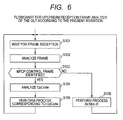
- the PHY/MAC receiver logic circuit 142 awaits a frame to be received.
- the PHY/MAC receiver logic circuit 142 analyzes the received frame.
- Control proceeds to S103.
- the PHY/MAC receiver logic circuit 142 determines whether the received frame is an MPCP control frame.
- control proceeds to S104.
- the MPCP control circuit 143 analyzes OpCode of the received frame.
- Control proceeds to S105.
- the MPCP control circuit 143 performs a process corresponding to OpCode.
- the present invention uses an additional control frame for the sleep mode to control switching between the sleep mode and the normal mode.
- control returns to S101.
- the PHY/MAC logic circuit determines at S102 that the received frame is not an MPCP control frame, control proceeds to S106.
- the NNI-IF circuit 15 performs the process.
- control returns to S101.
- the received frame may be identified as Sleep Request according to the OpCode analysis in the frame analysis at S104 in FIG. 6 .
- the MPCP control circuit 143 performs the following sleep process.
- the MPCP control circuit 143 passes control to S202 and starts the sleep process.
- the MPCP control circuit 143 then proceeds to S203 and determines whether to permit the sleep to the corresponding ONU.
- control proceeds to S204. Otherwise, control proceeds to S205.
- the MPCP control circuit 143 transmits Sleep Grant(NG) then proceeds to S209 to terminate the sleep process.
- the PHY/MAC transmitter logic circuit 141 also determines the sleep permission based on the presence or absence of a user frame to be transmitted to the ONU. When a user frame to be transmitted to the ONU is available, the PHY/MAC transmitter logic circuit 141 disallows the sleep.
- the MPCP control circuit 143 transmits Sleep Grant(OK) to the ONU and proceeds to 206.
- the Sleep Grant frame format will be described later with reference to FIG. 19 .
- the OLT manages that ONU as a sleep-mode ONU. The management method will be described later with reference to FIG. 22 .
- the MPCP control circuit 143 determines whether the sleep cancel time is reached.
- the determination uses the time supplied as TimeStamp when the frame is transmitted. Specifically, the MPCP control circuit 143 determines whether TimeStamp representing the current time precedes TimeStamp representing the sleep cancel time configured in the Sleep Grant frame. When the sleep cancel time is not reached, the MPCP control circuit 143 transmits Gate to the ONU and proceeds to S208.
- the Sleep Grant frame format will be described later with reference to FIG. 19 .
- the MPCP control circuit 143 need not transmit Gate to the ONU and therefore proceeds to S209 to terminate the sleep process.
- the MPCP control circuit 143 determines whether Sleep Cancel is received from the ONU. When receiving Sleep Cancel, the MPCP control circuit 143 proceeds to S209 to terminate the sleep process. When not receiving Sleep Cancel, the MPCP control circuit 143 returns to S206.
- the Sleep Cancel frame format will be described later with reference to FIG. 20 .
- the MPCP control circuit 143 By repeating the operation from S206 to S208, the MPCP control circuit 143 periodically transmits Gate to the sleep-mode ONU.
- the MPCP control circuit 143 stops transmitting Gate so as to be able to resume the normal operation. It may be preferable to manage cycles of Gate to be periodically transmitted to the sleep-mode ONU as will be described with reference to FIG. 21 .
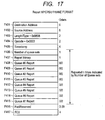
- the OLT maintains a management table as shown in FIG. 22 .
- the management table contains an ONU ID (identifier), an ONU registration state, and initialization parameters such as LLID for logical link, Ton for Laser ON time in ONU, Toff for Laser OFF time in ONU, and SyncTime for upstream transmission, for example.
- the ONU ID identifies an ONU to be connected to the OLT.
- the ONU registration state represents any one of registered, sleep, and unregistered states.
- the initialization parameters are determined when an ONU is registered during a discovery process. Even when the ONU enters the sleep state, the invention can keep the ONU registered by maintaining the initialization parameters.
- the OLT need not perform the discovery process for acquiring an initialization parameter when the ONU changes the sleep mode to the normal mode. As a result, it is possible to shorten the time for enabling the communication with the PON when the ONU changes the sleep mode to the normal mode.
- the initialization parameters in FIG. 22 are provided as an example and may include the other parameters, for example RTT(Round Trip Time) for each ONU.
- the PHY/MAC receiver logic circuit 242 awaits a frame to be received.
- the PHY/MAC receiver logic circuit 242 proceeds to S302 to analyze the received frame and then proceeds to S303.
- the PHY/MAC receiver logic circuit 242 determines whether the received frame is an MPCP control frame.
- the received frame is an MPCP control frame
- control proceeds to S304.
- the MPCP control circuit 243 analyzes OpCode and proceeds to S305.
- the MPCP control circuit 243 performs a process associated with OpCode.
- the present invention adds a control frame for the sleep mode to control switching between the sleep mode and the normal mode.
- control returns to S301.
- control proceeds to S306.
- the UNI-IF circuit performs a process. After the process terminates, control returns to S301.
- the received frame may be identified as Sleep Grant according to the OpCode analysis in the frame analysis.
- the ONU performs the sleep process.
- the ONU proceeds to S402 to start the sleep process.
- the ONU proceeds to S403 to start the sleep mode.
- the sleep control circuit 29 changes the components to the low power state to enable the sleep mode. Control then proceeds to S404.
- the sleep control circuit 29 determines whether the sleep cancel time is reached. The determination uses the time supplied as TimeStamp when the frame is transmitted. Specifically, the sleep control circuit 29 determines whether TimeStamp representing the current time precedes TimeStamp representing the sleep cancel time configured in the Sleep Grant frame. When it is determined that the sleep cancel time is not reached, control proceeds to S405. When it is determined that the sleep cancel time is reached, control proceeds to S408 to terminate the sleep process.
- the sleep control circuit 29 determines whether the PON communication is needed. For example, the PON communication is determined to be needed when an interface section with the terminal changes from the link-down state to the link-up state or when a user frame is received from the terminal. Otherwise, the PON communication is determined to be unneeded. When the PON communication is determined to be needed, the sleep control circuit 29 proceeds to S406. When the PON communication is determined to be unneeded, the sleep control circuit 29 returns to S404.
- the sleep mode is canceled. Specifically, the sleep control circuit 29 changes the components to the normal power state to cancel the sleep mode (to resume the normal mode).
- the sleep control circuit 29 transmits Sleep Cancel to the OLT 1.
- the sleep control circuit 29 determines the timing to transmit Sleep Cancel based on the Gate frame received from the OLT 1. After transmitting Sleep Cancel, the sleep control circuit 29 proceeds to S408 to terminate the sleep process.
- the sleep control circuit 29 determines the maximum sleep time and transmits Sleep Request to the OLT1.
- the OLT 1 determines availability of the sleep mode and the sleep cancel time for the ONU 2 and transmits Sleep Grant to the ONU 2.
- the ONU 2 enters the sleep mode until Sleep WakeUpTime specified in Sleep Grant. After entering the sleep mode, the ONU 2 may detect the state capable of communication in accordance with the terminal state before WakeUpTime as the sleep cancel time.
- the ONU 2 buffers data that is received from the terminal afterwards.
- the OLT assumes that the ONU 2 returns to the normal mode.
- the OLT transmits Gate to the ONU 2.
- the ONU 2 transmits Report to the OLT using the time and the period specified in Gate.
- the ONU 2 requests the upstream band allocation based on the amount of stored buffer.
- the OLT determines the upstream band allocation for the ONU based on a buffer size contained in Report.
- the OLT transmits Gate to the ONU.
- the ONU transmits upstream data to the OLT using the specified time and period.
- the OLT receives the upstream data and transfers it to the network.
- This operation causes a delay in the upstream data transfer because no upstream band is allocated until the sleep cancel time WakeUpTime is reached.
- the amount of upstream data delay depends on the specified sleep period.
- the OLT 1 and the ONU 2 are configured as shown in FIGS. 2 , 3 , 4 , and 5 .
- the ONU may detect that communication with the PON is unneeded. In this case, the ONU transmits Sleep Request containing the predetermined maximum sleep time to the OLT 1.
- the OLT 1 determines availability of the sleep mode and the sleep cancel time as described in FIG. 7 and transmits Sleep Grant to the ONU 2.
- the ONU 2 enters the sleep mode as described in FIG. 9 .
- the OLT continues transmitting Gate based on the predetermined cycle and upstream band allocation to the ONU in the sleep mode. Even before the sleep cancel time, the ONU can change from the sleep mode to the normal mode. While in the sleep mode, the ONU does not or cannot respond to Gate.
- the ONU When detecting the state capable of communication based on the terminal state, the ONU cancels the sleep mode before sleep cancel time WakeUpTime as described in FIG. 9 . Further, as described in FIG. 9 , the ONU transmits Sleep Cancel Report using the time and the period specified in Gate received from the OLT. When receiving Sleep Cancel Report, the OLT terminates the sleep process for the ONU as described in FIG. 7 . The OLT then transmits Gate to the ONU. After detecting the state capable of communication as described in FIG. 7 , the ONU buffers upstream data received from the terminal. When receiving Gate from the OLT after transmission of Sleep Cancel Report, the ONU transmits Report to the OLT based on a buffer size stored in the ONU and requests the upstream band allocation.
- the OLT determines the upstream band to be allocated to the ONU and transmits Gate.
- the ONU transmits upstream data to the OLT using the allocated band.
- the OLT receives the upstream data from the ONU and transfers it to the network.
- This operation enables communication with the PON before the sleep cancel time WakeUpTime while preventing the use efficiency of upstream bands from degrading.
- a delay in the upstream data transfer can be decreased.
- the amount of upstream data delay depends on the cycle of Gate transmitted from the OLT during the sleep period, not on the predetermined sleep time.
- FIG. 14 shows a frame format used for EPON.
- OpCode F105 contains a value indicating the control frame type.
- Fields F101 to F108 are the same as those in the frame format defined in IEEE 802.3av and a description is omitted for simplicity.
- FIGS. 17 , 18, and 19 show MPCP control frame formats for Normal Gate, Discovery Gate, and Report frames, respectively. These frame formats are the same as those defined in IEEE 802.3av and a description is omitted for simplicity.
- OpCode F504 contains a value representing Sleep Request. The value is set to 0x0007 in this embodiment and may be otherwise specified so as to be compliant with the IEEE 802.3av standard.
- Max Sleep Time F506 contains the maximum sleep time the ONU requests from the OLT. Based on Max Sleep Time, the OLT determines WakeUpTime, i.e., the time to cancel the sleep mode. An appropriate sleep time may depend on ONUs, the traffic state of each ONU, or time slots. The ONU needs to notify an appropriate sleep time. The maximum value is input because an available sleep time may be restricted due to limitations on a counter for timekeeping in the ONU.
- the other fields are the same as those defined in IEEE 802.3av and a description is omitted for simplicity.
- OpCode F604 contains a value representing Sleep Grant. The value is set to Ox0008 in this embodiment and may be otherwise specified so as to be compliant with the IEEE 802.3av standard.
- Sleep Permission F606 contains a value representing whether to permit the sleep. For example, value 0x01 permits the sleep. Value 0x02 does not permit the sleep.
- WakeUpTime F607 contains the time when the ONU cancels the sleep mode. The ONU cancels the sleep mode by the time specified in WakeUpTime. Resuming the normal mode from the sleep mode takes time.
- the ONU passes control from the sleep mode to the normal mode early enough to compensate for the recovery time.
- the ONU cancels the sleep mode even before the time specified in WakeUpTime when detecting the need for communication with the PON because a terminal connected to the ONU becomes capable of communication, for example.
- the other fields are the same as those defined in IEEE 802.3av and a description is omitted for simplicity.
- OpCode F704 contains a value representing Sleep Cancel Report.
- the value is set to Ox0009 in this embodiment and may be otherwise specified so as to be compliant with the IEEE 802.3av standard.
- the frame format itself is the same as the Report frame and differs from it in the OpCode value.
- the above-mentioned Sleep Cancel Report frame is provided as an example.
- the Report frame may replace the Sleep Cancel Report frame.
- the Sleep Cancel Report frame format may differ from the Report frame format. While the Report frame format contains eight Queue Report fields, the Sleep Cancel Report frame format may contain four Queue Report fields, for example.
- the communication with the PON can be resumed in a short period of time even before the sleep cancel time while the use efficiency of upstream bands is prevented from degrading. Since a long sleep period can be specified, the power consumption is lower than conventional technologies.
- the ONU transmits Sleep Cancel Report, then receives Gate, transmits Report, receives Gate, and transmits upstream data to resume the normal state.
- the second embodiment eliminates one reciprocation of receiving Gate and transmitting Report. That is, the ONU transmits Sleep Cancel Report, then receives Gate, and transmits upstream data to resume the normal state.
- the ONU requests a predetermined upstream band when transmitting Sleep Cancel Report. That is, the ONU always requests a specified band even when the amount of upstream buffer is zero.
- the OLT determines the band allocation for the ONU based on the upstream band request in Sleep Cancel Report and transmits Gate to the ONU.
- the ONU transmits upstream data to the OLT at the time specified in Gate.
- the OLT transfers the upstream data received from the ONU to the network.
- the second embodiment can resume the communication with the PON in a shorter period of time than the first embodiment.
- the ONU transmits Sleep Cancel Report, then receives Gate, and transmits upstream data to resume the normal state.
- the ONU transmits Sleep Cancel Report and then transmits upstream data without receiving Gate to resume the normal state.
- Gate transmitted from the OLT to the sleep-mode ONU allocates only the band transmitted in Sleep Cancel Report.
- Gate transmitted from the OLT to the sleep-mode ONU always allocates a predetermined band in addition to the band transmitted in Sleep Cancel Report. After detecting a state capable of communication, the ONU receives Gate from the OLT, uses the allocated band, and transmits Sleep Cancel Report and upstream data.
- the third embodiment can resume the communication with the PON in a much shorter period of time than the second embodiment.
- the third embodiment allocates an extra band to the sleep-mode ONU, degrading the upstream band use efficiency.
- a band to be allocated to the sleep-mode ONU is determined based on upstream band requests from the other ONUs.
- the first, second, and third embodiments have described the interoperation between a single ONU and the OLT.
- the amount of delay allowable for a subscriber or an ONU is not always constant. Therefore, all ONUs in the sleep mode need not be given constant values for the transmission cycle and the allocation band of the Gate to be transmitted to the ONUs. In this case, a band allocation management table in sleep mode is needed as will be described with reference to FIG. 21 .
- the band allocation management table in sleep mode contains an ONU ID, a gate transmission cycle in sleep mode, and a band allocated in sleep mode.
- the ONU ID identifies an ONU connected to the OLT and takes any of values 1 to n, where n is the number of PON branches.
- An ONU MAC address may replace the ONU ID.
- the gate transmission cycle in sleep mode represents the cycle of Gate that is periodically transmitted to the sleep-mode ONU.
- EPON transmits Gate at a DBA cycle of T_dba. The cycle can be easily specified when it is equal to the integral multiple of T_dba.
- the band allocated in sleep mode represents the amount of upstream band allocated in Gate to be transmitted to the sleep-mode ONU.
- the band allocation management table in sleep mode is configured before an ONU is connected and the service starts. Values in the table may be changed during operation. For example, the values can be changed from an operation and maintenance terminal connected to the OLT via the network. The values depend on the service quality needed for each ONU. For example, there may be a need to reduce the ONU power consumption despite a long delay time. In such a case, the table contains a long gate transmission cycle in sleep mode and a small band allocated in sleep mode.
Landscapes
- Engineering & Computer Science (AREA)
- Computer Networks & Wireless Communication (AREA)
- Small-Scale Networks (AREA)
- Optical Communication System (AREA)
Applications Claiming Priority (1)
| Application Number | Priority Date | Filing Date | Title |
|---|---|---|---|
| JP2010041269A JP5463165B2 (ja) | 2010-02-26 | 2010-02-26 | 省電力化可能なponシステムにおける、onuのスリープ状態からの復旧方法 |
Publications (2)
| Publication Number | Publication Date |
|---|---|
| EP2362675A2 true EP2362675A2 (de) | 2011-08-31 |
| EP2362675A3 EP2362675A3 (de) | 2016-04-06 |
Family
ID=44148741
Family Applications (1)
| Application Number | Title | Priority Date | Filing Date |
|---|---|---|---|
| EP10016204.9A Withdrawn EP2362675A3 (de) | 2010-02-26 | 2010-12-30 | Wiederherstellung einer optischen Netzeinheit aus einem Ruhezustand |
Country Status (4)
| Country | Link |
|---|---|
| US (1) | US8705965B2 (de) |
| EP (1) | EP2362675A3 (de) |
| JP (1) | JP5463165B2 (de) |
| CN (1) | CN102170598B (de) |
Cited By (3)
| Publication number | Priority date | Publication date | Assignee | Title |
|---|---|---|---|---|
| JP2014127803A (ja) * | 2012-12-26 | 2014-07-07 | Nippon Telegr & Teleph Corp <Ntt> | ユーザ側光回線終端装置およびユーザ側光回線終端装置の消費電力制御方法 |
| CN105025400A (zh) * | 2014-04-18 | 2015-11-04 | 美国博通公司 | 无源光网络(pon)中的概率性带宽控制 |
| EP3229387A4 (de) * | 2014-12-29 | 2018-04-04 | Huawei Technologies Co. Ltd. | Verfahren, vorrichtung und system zum aufwecken einer optischen netzwerkeinheit in einem passiven optischen netzwerk |
Families Citing this family (31)
| Publication number | Priority date | Publication date | Assignee | Title |
|---|---|---|---|---|
| JP4700094B2 (ja) * | 2008-10-24 | 2011-06-15 | 株式会社日立製作所 | 光アクセスシステム及び光回線装置 |
| JP5263394B2 (ja) * | 2009-06-16 | 2013-08-14 | 富士通オプティカルコンポーネンツ株式会社 | 光通信装置及び光通信装置の節電制御方法 |
| CN102474439B (zh) * | 2009-07-14 | 2014-01-08 | 三菱电机株式会社 | 光终端站装置以及pon系统 |
| US8422887B2 (en) * | 2010-01-31 | 2013-04-16 | Pmc Sierra Ltd | System for redundancy in Ethernet passive optical networks (EPONs) |
| JP5434808B2 (ja) * | 2010-06-09 | 2014-03-05 | 住友電気工業株式会社 | データ中継装置及びその機能制御方法 |
| US20120045202A1 (en) * | 2010-08-17 | 2012-02-23 | Xu Jiang | High Speed Bi-Directional Transceiver, Circuits and Devices Therefor, and Method(s) of Using the Same |
| KR101327554B1 (ko) * | 2010-12-23 | 2013-11-20 | 한국전자통신연구원 | 광망종단 장치 및 그것의 전력 절감 방법 |
| US8958699B2 (en) * | 2011-03-22 | 2015-02-17 | Telefonaktiebolaget L M Ericsson (Publ) | ONU with wireless connectivity capability |
| JP5790097B2 (ja) * | 2011-04-04 | 2015-10-07 | 沖電気工業株式会社 | 加入者側端末装置及び加入者側端末装置の消費電力制御方法 |
| US8699885B2 (en) * | 2011-05-12 | 2014-04-15 | Cortina Systems, Inc. | Power control in an optical network unit |
| JP5380689B2 (ja) * | 2011-05-30 | 2014-01-08 | 株式会社日立製作所 | 光回線装置、帯域制御方法、及び、光ネットワークシステム |
| US8976688B2 (en) | 2011-06-17 | 2015-03-10 | Calix, Inc. | Grant scheduler for optical network devices |
| US8917993B2 (en) * | 2011-06-17 | 2014-12-23 | Calix, Inc. | Scheduling delivery of upstream traffic based on downstream traffic in optical networks |
| US8850244B2 (en) * | 2011-06-21 | 2014-09-30 | Cisco Technology, Inc. | Wake-on-LAN between optical link partners |
| CN103002515B (zh) * | 2011-09-16 | 2017-11-24 | 华为技术有限公司 | 静默模式指示方法、静默模式下的数据传输方法及装置 |
| JP5746003B2 (ja) * | 2011-11-15 | 2015-07-08 | 日本電信電話株式会社 | 送受信方法 |
| KR20130085523A (ko) * | 2011-12-15 | 2013-07-30 | 한국전자통신연구원 | 저전력 광망 종단 장치 및 저전력 광망 종단 장치의 동작 방법 |
| US8948586B2 (en) | 2011-12-15 | 2015-02-03 | Cortina Access, Inc. | Method and apparatus for laser overlap detection |
| CN102752043B (zh) * | 2012-06-11 | 2015-02-25 | 烽火通信科技股份有限公司 | 低功耗的智能odn系统 |
| JP6009074B2 (ja) * | 2012-07-13 | 2016-10-19 | ゼットティーイー コーポレーションZte Corporation | 受動光ネットワークにおける光ネットワークユニット電力管理 |
| JP5792132B2 (ja) * | 2012-08-24 | 2015-10-07 | 日本電信電話株式会社 | 通信制御方法、局側通信装置、加入者系ポイント・トゥ・マルチポイント型光通信システム、及び記録媒体 |
| JP5876584B2 (ja) * | 2012-09-27 | 2016-03-02 | 日本電信電話株式会社 | 光無線アクセスシステム |
| US9432755B2 (en) | 2013-02-15 | 2016-08-30 | Futurewei Technologies, Inc. | Downstream burst transmission in passive optical networks |
| JP5997088B2 (ja) * | 2013-03-29 | 2016-09-28 | 株式会社日立製作所 | 動的帯域割当方法、olt、及びponシステム |
| KR102061498B1 (ko) | 2013-10-11 | 2020-02-11 | 한국전자통신연구원 | 슬립모드 onu 제어 기법 |
| CN104981990B (zh) * | 2013-12-30 | 2018-06-05 | 华为技术有限公司 | 检测上行光信号的功率的方法、装置、光线路终端和光网络系统 |
| JP6408274B2 (ja) * | 2014-07-22 | 2018-10-17 | 日本電信電話株式会社 | 通信装置及び制御方法 |
| CN110213679B (zh) * | 2016-12-02 | 2021-09-10 | 中兴通讯股份有限公司 | 一种无源光网络系统及其实现方法 |
| CN112136343B (zh) * | 2018-06-19 | 2024-01-12 | 奥林巴斯株式会社 | 无线通信终端、无线通信系统、无线通信方法及存储介质 |
| US20230040541A1 (en) * | 2021-08-05 | 2023-02-09 | Charter Communications Operating, Llc | Power Saving For Multi-Wavelength Passive Optical Network (PON) |
| KR102644304B1 (ko) | 2021-11-23 | 2024-03-07 | 한국전자통신연구원 | 슬라이싱 기능을 지원하는 onu의 전원 관리 방법 및 장치 |
Citations (2)
| Publication number | Priority date | Publication date | Assignee | Title |
|---|---|---|---|---|
| JP2003517741A (ja) | 1998-08-14 | 2003-05-27 | テレフォンアクチーボラゲット エル エム エリクソン(パブル) | 接続を確立している移動端末機における省電力化のための方法及び装置 |
| JP2004172772A (ja) | 2002-11-18 | 2004-06-17 | Nec Corp | 無線通信システム |
Family Cites Families (27)
| Publication number | Priority date | Publication date | Assignee | Title |
|---|---|---|---|---|
| US5905443A (en) * | 1995-10-02 | 1999-05-18 | Motorola, Inc. | Paging system employing delivery schedule combining and method of operation thereof |
| US6735454B1 (en) * | 1999-11-04 | 2004-05-11 | Qualcomm, Incorporated | Method and apparatus for activating a high frequency clock following a sleep mode within a mobile station operating in a slotted paging mode |
| BRPI0107141B1 (pt) | 2000-08-25 | 2015-06-16 | Sony Corp | Sistema de rádiodifusão digital, transmissor de rádiodifusão digital, receptor de rádiodifusão digital, e, método de rádiodifusão digital |
| US6563307B2 (en) * | 2001-08-03 | 2003-05-13 | General Electric Company | Eddy current inspection probe |
| JP4983033B2 (ja) * | 2006-02-08 | 2012-07-25 | ソニー株式会社 | 通信装置および方法、並びにプログラム |
| KR101388932B1 (ko) | 2006-07-14 | 2014-04-24 | 코닌클리케 필립스 엔.브이. | 비컨 송·수신의 방법 및 시스템 |
| JP4410789B2 (ja) * | 2006-12-08 | 2010-02-03 | 株式会社日立コミュニケーションテクノロジー | パッシブ光ネットワークシステム、光終端装置及び光ネットワークユニット |
| JP4388556B2 (ja) * | 2007-01-09 | 2009-12-24 | 株式会社日立コミュニケーションテクノロジー | パッシブ光ネットワークシステムおよび波長割当方法 |
| CN101378291A (zh) * | 2007-08-28 | 2009-03-04 | 华为技术有限公司 | 传输测试数据的方法、设备及系统 |
| JP5072614B2 (ja) * | 2008-01-18 | 2012-11-14 | 日本電信電話株式会社 | 加入者宅内装置、局内装置及び光加入者系アクセスシステム |
| ATE490612T1 (de) * | 2008-01-30 | 2010-12-15 | Alcatel Lucent | Verfahren zur überwachung eines passiven optischen netzes unter verwendung von überwachungseinheiten |
| US8275261B2 (en) * | 2008-04-17 | 2012-09-25 | Pmc Sierra Ltd | Power saving in IEEE 802-style networks |
| US8000602B2 (en) * | 2008-04-17 | 2011-08-16 | Pmc-Sierra Israel Ltd. | Methods and devices for reducing power consumption in a passive optical network while maintaining service continuity |
| WO2009142425A2 (en) * | 2008-05-19 | 2009-11-26 | Samsung Electronics Co., Ltd. | Apparatus and method for saving power of femto base station in wireless communication system |
| EP2685745B1 (de) * | 2009-02-24 | 2015-07-29 | Nippon Telegraph And Telephone Corporation | Optisches Leitungsendgerät und optisches Netzwerk |
| JP5277071B2 (ja) * | 2009-05-25 | 2013-08-28 | 株式会社日立製作所 | 光アクセスシステム、光集線装置および光加入者装置 |
| CN102474439B (zh) * | 2009-07-14 | 2014-01-08 | 三菱电机株式会社 | 光终端站装置以及pon系统 |
| WO2011019992A1 (en) * | 2009-08-13 | 2011-02-17 | New Jersey Institute Of Technology | Scheduling wdm pon with tunable lasers with different tuning times |
| KR101412441B1 (ko) * | 2009-08-21 | 2014-06-25 | 미쓰비시덴키 가부시키가이샤 | Pon 시스템, 가입자측 종단 장치, 국측 종단 장치 및 파워 세이브 방법 |
| EP2541993A1 (de) * | 2010-02-22 | 2013-01-02 | Nec Corporation | Mobilkommunikationsendgerät, netzwerkvorrichtung, mobilkommunikationssystem, programmierungsverfahren und mobilkommunikationssystem zur änderung eines betriebszeitraums |
| JP4812884B2 (ja) * | 2010-04-13 | 2011-11-09 | 三菱電機株式会社 | 通信システム、局側光回線終端装置、利用者側光回線終端装置、制御装置、並びに通信方法 |
| JP5143866B2 (ja) * | 2010-06-07 | 2013-02-13 | 株式会社日立製作所 | 光アクセスシステム、光ネットワーク装置、及び、光回線装置 |
| CN102377489B (zh) * | 2010-08-19 | 2015-12-16 | 韩国电子通信研究院 | 光用户网络 |
| US8600231B2 (en) * | 2010-08-19 | 2013-12-03 | Telefonaktiebolaget Lm Ericsson (Publ) | Monitoring energy consumption in optical access networks |
| US8477650B2 (en) * | 2010-09-10 | 2013-07-02 | Oliver Solutions Ltd. | Power management for passive optical networks |
| JP5483593B2 (ja) * | 2010-11-04 | 2014-05-07 | 株式会社日立製作所 | 受動網光システム及びスリープタイム決定方法 |
| US8761065B2 (en) * | 2010-11-16 | 2014-06-24 | Intel Corporation | Techniques for wakeup signaling for a very low power WLAN device |
-
2010
- 2010-02-26 JP JP2010041269A patent/JP5463165B2/ja not_active Expired - Fee Related
- 2010-12-30 EP EP10016204.9A patent/EP2362675A3/de not_active Withdrawn
-
2011
- 2011-01-10 US US12/987,753 patent/US8705965B2/en not_active Expired - Fee Related
- 2011-01-26 CN CN201110028105.4A patent/CN102170598B/zh not_active Expired - Fee Related
Patent Citations (2)
| Publication number | Priority date | Publication date | Assignee | Title |
|---|---|---|---|---|
| JP2003517741A (ja) | 1998-08-14 | 2003-05-27 | テレフォンアクチーボラゲット エル エム エリクソン(パブル) | 接続を確立している移動端末機における省電力化のための方法及び装置 |
| JP2004172772A (ja) | 2002-11-18 | 2004-06-17 | Nec Corp | 無線通信システム |
Cited By (7)
| Publication number | Priority date | Publication date | Assignee | Title |
|---|---|---|---|---|
| JP2014127803A (ja) * | 2012-12-26 | 2014-07-07 | Nippon Telegr & Teleph Corp <Ntt> | ユーザ側光回線終端装置およびユーザ側光回線終端装置の消費電力制御方法 |
| CN105025400A (zh) * | 2014-04-18 | 2015-11-04 | 美国博通公司 | 无源光网络(pon)中的概率性带宽控制 |
| EP2953375A3 (de) * | 2014-04-18 | 2016-03-02 | Broadcom Corporation | Probabilistische bandbreitensteuerung in einem passiven optischen netzwerk (pon) |
| US9432120B2 (en) | 2014-04-18 | 2016-08-30 | Broadcom Corporation | Probabilistic bandwidth control in a passive optical network (PON) |
| CN105025400B (zh) * | 2014-04-18 | 2019-05-14 | 安华高科技股份有限公司 | 无源光网络(pon)中的概率性带宽控制 |
| EP3229387A4 (de) * | 2014-12-29 | 2018-04-04 | Huawei Technologies Co. Ltd. | Verfahren, vorrichtung und system zum aufwecken einer optischen netzwerkeinheit in einem passiven optischen netzwerk |
| US10284298B2 (en) | 2014-12-29 | 2019-05-07 | Huawei Technologies Co., Ltd. | Method for awaking optical network unit in passive optical network, device, and system |
Also Published As
| Publication number | Publication date |
|---|---|
| US20110211837A1 (en) | 2011-09-01 |
| EP2362675A3 (de) | 2016-04-06 |
| JP2011181990A (ja) | 2011-09-15 |
| JP5463165B2 (ja) | 2014-04-09 |
| US8705965B2 (en) | 2014-04-22 |
| CN102170598B (zh) | 2015-06-24 |
| CN102170598A (zh) | 2011-08-31 |
Similar Documents
| Publication | Publication Date | Title |
|---|---|---|
| US8705965B2 (en) | Method of recovery from sleep state of an ONU in a PON system capable of power saving | |
| EP2552057B1 (de) | Kommunikationsverfahren, optisches kommunikationssystem, optischer leitungsanschluss und optische netzwerkeinheit | |
| US9106984B2 (en) | PON system, subscriber-side terminal apparatus, station-side terminal apparatus, and power saving method | |
| US9130677B2 (en) | Communication system, station-side optical line terminating apparatus, user-side optical line terminating apparatus, control apparatus, and communication method | |
| EP2615800B1 (de) | Kommunikationsverfahren für ein optisches kommunikationssystem, optisches kommunikationssystem, nebenstationsgerät, steuervorrichtung und programm | |
| EP2728808B1 (de) | Teilnehmerseitige optische kommunikationsvorrichtung, kommunikationssystem, steuervorrichtung und energiesparendes steuerungsverfahren | |
| US8699885B2 (en) | Power control in an optical network unit | |
| US20120128349A1 (en) | Passive optical network system, station side apparatus and power consumption control method | |
| US8798460B2 (en) | Optical access system, optical network unit, and optical line terminal | |
| WO2010107884A2 (en) | Methods and apparatus for extending mac control messages in epon | |
| US8873957B2 (en) | Logical-link management method and communication device | |
| US8886041B2 (en) | Optical line terminal, bandwidth control method and optical network system | |
| WO2011083564A1 (ja) | Ponシステム、加入者側装置、局側装置および通信方法 | |
| JP2012257341A (ja) | 通信方法、光通信システム、利用者側光回線終端装置、局側光回線終端装置および制御装置 | |
| JP5577520B2 (ja) | 通信システム、子局装置、及び、親局装置 | |
| JP2013026774A (ja) | 通信制御方法、通信システム、局側装置および宅側装置 | |
| JP2014045248A (ja) | 通信制御方法、局側通信装置、加入者系ポイント・トゥ・マルチポイント型光通信システム、及び記録媒体 |
Legal Events
| Date | Code | Title | Description |
|---|---|---|---|
| PUAI | Public reference made under article 153(3) epc to a published international application that has entered the european phase |
Free format text: ORIGINAL CODE: 0009012 |
|
| 17P | Request for examination filed |
Effective date: 20110428 |
|
| AK | Designated contracting states |
Kind code of ref document: A2 Designated state(s): AL AT BE BG CH CY CZ DE DK EE ES FI FR GB GR HR HU IE IS IT LI LT LU LV MC MK MT NL NO PL PT RO RS SE SI SK SM TR |
|
| AX | Request for extension of the european patent |
Extension state: BA ME |
|
| RIN1 | Information on inventor provided before grant (corrected) |
Inventor name: SUGAWA, JUN Inventor name: KAZAWA, TOHRU Inventor name: IKEDA, HIROKI |
|
| PUAL | Search report despatched |
Free format text: ORIGINAL CODE: 0009013 |
|
| AK | Designated contracting states |
Kind code of ref document: A3 Designated state(s): AL AT BE BG CH CY CZ DE DK EE ES FI FR GB GR HR HU IE IS IT LI LT LU LV MC MK MT NL NO PL PT RO RS SE SI SK SM TR |
|
| AX | Request for extension of the european patent |
Extension state: BA ME |
|
| RIC1 | Information provided on ipc code assigned before grant |
Ipc: H04Q 11/00 20060101AFI20160302BHEP |
|
| STAA | Information on the status of an ep patent application or granted ep patent |
Free format text: STATUS: THE APPLICATION IS DEEMED TO BE WITHDRAWN |
|
| 18D | Application deemed to be withdrawn |
Effective date: 20161007 |