EP2360444A1 - Unite d'echange de chaleur composite - Google Patents
Unite d'echange de chaleur composite Download PDFInfo
- Publication number
- EP2360444A1 EP2360444A1 EP09829056A EP09829056A EP2360444A1 EP 2360444 A1 EP2360444 A1 EP 2360444A1 EP 09829056 A EP09829056 A EP 09829056A EP 09829056 A EP09829056 A EP 09829056A EP 2360444 A1 EP2360444 A1 EP 2360444A1
- Authority
- EP
- European Patent Office
- Prior art keywords
- heat exchanger
- refrigerant
- air
- cooled heat
- flow
- Prior art date
- Legal status (The legal status is an assumption and is not a legal conclusion. Google has not performed a legal analysis and makes no representation as to the accuracy of the status listed.)
- Withdrawn
Links
Images


Classifications
-
- F—MECHANICAL ENGINEERING; LIGHTING; HEATING; WEAPONS; BLASTING
- F28—HEAT EXCHANGE IN GENERAL
- F28F—DETAILS OF HEAT-EXCHANGE AND HEAT-TRANSFER APPARATUS, OF GENERAL APPLICATION
- F28F9/00—Casings; Header boxes; Auxiliary supports for elements; Auxiliary members within casings
- F28F9/02—Header boxes; End plates
- F28F9/0234—Header boxes; End plates having a second heat exchanger disposed there within, e.g. oil cooler
-
- F—MECHANICAL ENGINEERING; LIGHTING; HEATING; WEAPONS; BLASTING
- F28—HEAT EXCHANGE IN GENERAL
- F28D—HEAT-EXCHANGE APPARATUS, NOT PROVIDED FOR IN ANOTHER SUBCLASS, IN WHICH THE HEAT-EXCHANGE MEDIA DO NOT COME INTO DIRECT CONTACT
- F28D1/00—Heat-exchange apparatus having stationary conduit assemblies for one heat-exchange medium only, the media being in contact with different sides of the conduit wall, in which the other heat-exchange medium is a large body of fluid, e.g. domestic or motor car radiators
- F28D1/02—Heat-exchange apparatus having stationary conduit assemblies for one heat-exchange medium only, the media being in contact with different sides of the conduit wall, in which the other heat-exchange medium is a large body of fluid, e.g. domestic or motor car radiators with heat-exchange conduits immersed in the body of fluid
- F28D1/04—Heat-exchange apparatus having stationary conduit assemblies for one heat-exchange medium only, the media being in contact with different sides of the conduit wall, in which the other heat-exchange medium is a large body of fluid, e.g. domestic or motor car radiators with heat-exchange conduits immersed in the body of fluid with tubular conduits
- F28D1/0408—Multi-circuit heat exchangers, e.g. integrating different heat exchange sections in the same unit or heat exchangers for more than two fluids
- F28D1/0426—Multi-circuit heat exchangers, e.g. integrating different heat exchange sections in the same unit or heat exchangers for more than two fluids with units having particular arrangement relative to the large body of fluid, e.g. with interleaved units or with adjacent heat exchange units in common air flow or with units extending at an angle to each other or with units arranged around a central element
- F28D1/0452—Combination of units extending one behind the other with units extending one beside or one above the other
Definitions
- the present invention relates to a combined heat exchanger that uses plural types of refrigerants (e.g. engine coolant and air-conditioning refrigerant) in a cooling cycle for an automobile.
- refrigerants e.g. engine coolant and air-conditioning refrigerant
- a heat exchanger is disclosed in Japanese Patent Application Laid-Open No. 2006-162176 [Patent Document 1].
- This heat exchanger is used in an air conditioner for a vehicle, and a heat exchanger for air-conditioning refrigerant is implemented in a tank (header) of an air-cooled heat exchanger for engine coolant to cool air-conditioning refrigerant by air-cooled coolant.
- the refrigerant is flown into from its lower side and frown out from its upper side.
- Oil for a compressor is subject to be mixed in air-conditioning refrigerant, and the refrigerant circulates in a system together with the mixed oil. Some of the mixed oil separates from the refrigerant.
- the refrigerant flows from its lower side to its upper side, so that it may happen that the oil stays at a lower portion of the heat exchanger. If the oil stays, there are concerns of degradation of heat-exchange efficiency, or degradation of performance and reliability of a cooling system due to insufficient lubrication in the compressor.
- a recent vehicle has heat generators such as an internal combustion engine, an intercooler for supercharging, an air conditioner and an electric motor for a hybrid electric vehicle. Therefore, a compact and effective heat exchanger (combined heat exchanger) is desired to cool these heat generators (to exhaust heat of the heat generators) .
- An object of the present invention is to provide a combined heat exchanger that can prevent oil mixed in refrigerant from staying, and thereby it is superior in heat exchange effectiveness and compact.
- An aspect of the present invention provides a combined heat exchanger used for a cooling system that includes a first air-cooled heat exchanger for cooling coolant for a heat generator other than an internal combustion engine in an automobile and a second air-cooled heat exchanger for cooling refrigerant for air-conditioning, wherein the first air-cooled heat exchanger includes an upstream tank into which the coolant flows, a downstream tank form which the refrigerant flows out, flow channel members that communicate the upstream tank with the downstream tank, heat release fins that are alternately stacked with the flow channel members, and a water-cooled heat exchanger for cooling the refrigerant; the water-cooled heat exchanger is disposed within the upstream tank or the downstream tank, and includes an inlet port to which the refrigerant flows at an upper portion thereof and an outlet port from which the refrigerant flows out at a lower portion thereof; and the second air-cooled heat exchanger is disposed below the first air-cooled heat exchanger and the refrigerant that flown out from the water-cooled heat exchanger flows into the
- the refrigerant is flown into the water-cooled heat exchanger from the inlet port at the upper portion, and flown out from the outlet port at the lower portion. Therefore, oil is prevented from staying at the lower portion, and thereby heat exchange efficiency improves. In addition, insufficient lubrication in a compressor, and degradation of performance and reliability of the cooling system due to the oil-staying are prevented.
- the water-cooled heat exchanger is disposed within the downstream tank. According to this, since the water-cooled heat exchanger is disposed within the downstream tank within which the cooled coolant circulates, high heat exchange efficiency can be brought.
- first air-cooled heat exchanger and the second air-cooled heat exchanger are disposed adjacent to each other on a plane perpendicular to a flow of cooling air therethrough.
- the combined heat exchanger can be configured extremely compact, and thereby exerts superior performance in its installation to a vehicle.
- the combined heat exchanger is used in a cooling system in a vehicle, and thereby can effectively cool heat generators such as an engine, an intercooler for a super-charging unit, an air-conditioner and a drive motor in a hybrid electric vehicle.
- the water-cooled heat exchanger is configured by stacking a plurality of refrigerant flow-passage units as flow passage of the refrigerant with gaps therebetween, the coolant flowing through the gaps, and each of the refrigerant flow-passage units is oriented vertically.
- each of the refrigerant flow-passage units is formed almost circularly rounded.
- each of the refrigerant flow-passage units includes a shell tube on which an inflow port communicating with the inlet port and an outflow port communicating with the outlet port are formed near both ends thereof in a flow direction of the refrigerant, and an inner fin that is fixed in the shell tube and on which an inflow hole corresponding to the inflow port, an outflow hole corresponding to the outflow port and a plurality of grooves along a flow of the refrigerant are formed; and a slit extended from the inflow hole and a slit extended from the outflow hole are formed on the inner fin.
- the refrigerant is spread and then collected in a direction perpendicular to its flow due to the slits extended from the inflow hole and the outflow hole. Therefore, the heat exchange efficiency and the restraining effect of oil-staying improve.
- the inner fin is fixed within the shell tube, anti-pressure strength of the shell tube is kept high.
- each of the refrigerant flow-passage units includes a shell tube on which an inflow port communicating with the inlet port and an outflow port communicating with the outlet port are formed near both ends thereof in a flow direction of the refrigerant, and an inner fin that is fixed in the shell tube and on which an inflow hole corresponding to the inflow port, an outflow hole corresponding to the outflow port and a plurality of grooves along a flow of the refrigerant are formed; and a notch along an edge on a side of the inflow hole and a notch along an edge on a side of the outflow hole are formed on the inner fin.
- the refrigerant is spread and then collected in a direction perpendicular to its flow due to the notches formed along the edge on the side of the inflow hole and the edge on the side of the outflow hole on the inner fin. Therefore, the heat exchange efficiency and the restraining effect of oil-staying improve.
- the inner fin is fixed within the shell tube, anti-pressure strength of the shell tube is kept high.
- a combined heat exchanger 1 according to a first embodiment will be explained with reference to Figs. 1 to 7 .
- the combined heat exchanger 1 is used in a cooling system 9 in a hybrid electric vehicle that has an engine (internal combustion engine: not shown) and an electric motor 3 as sources of a driving force.
- the combined heat exchanger 1 is used in the cooling system 9 that includes a sub-radiator 5 (first air-cooled heat exchanger) and a condenser 7 (second air-cooled heat exchanger) as shown in Fig. 1 .
- the sub-radiator 5 cools coolant for the drive motor 3 and control devices (heat generators other than the engine) such as an inverter or a converter.
- the condenser 7 cools air-conditioning refrigerant.
- the sub-radiator 5 includes an upstream tank 11, a downstream tank 13, flat tubes 15 (flow channel members), heat release fins 17, and a water-cooled heat exchanger 19 as shown in Figs. 1 to 3 .
- the coolant flows into the upstream tank 11 and then flows out from the downstream tank 13.
- the upstream tank 11 is communicated with the downstream tank 13 by the flat tubes 15.
- the heat release fins 17 are alternately stacked with the flat tubes 15.
- the water-cooled heat exchanger 19 cools the air-conditioning refrigerant (as explained above, the refrigerant is also cooled by the condenser 7).
- the water-cooled heat exchanger 19 is disposed within the downstream tank 13.
- the condenser 7 is disposed below the sub-radiator 5 as shown in Fig. 2 .
- the refrigerant flows into the water-cooled heat exchanger 19 from an upper side of the water-cooled heat exchanger 19, and then flows out from a lower side of the water-cooled heat exchanger 19, as shown in Fig. 5 .
- the refrigerant that has flown out from the water-cooled heat exchanger 19 flows down to the condenser 7.
- the sub-radiator 5 and the condenser 7 are disposed on a plane that is almost perpendicular to a flow of cooling air (outside air inflowing from a front grill during a vehicle running) for cooling them.
- the sub-radiator 5 and the condenser 7 are disposed adjacent to each other.
- the water-cooled heat exchanger 19 is configured by stacking plural shell tubes (refrigerant flow-passage units) 21 as flow passages of the refrigerant with gaps 25 therebetween.
- the coolant in the downstream tank 13 flows through the gaps 25.
- Each of the shell tubes 21 is oriented vertically so as to flow the refrigerant in a vertical direction (gravity direction).
- Upper and lower end (at least a lower end) of each of the shell tubes are formed almost circularly rounded.
- reinforcements 26 are attached to upper and lower end of the stacked flat tubes 15 of the sub-radiator 5, respectively.
- the flat tubes 15 are subject to an adequate load with sandwiched between the reinforcements 26, and their both ends are inserted into the tanks 11 and 13.
- the sub-radiator 5 and the condenser 7 are disposed vertically. Then, a radiator 27 for the engine is disposed at a downstream of cooling air passing through the sub-radiator 5 and the condenser 7. The engine coolant is cooled by the cooling air in the radiator 27.
- the water-cooled heat exchanger 19 is configured by the shell tubes (refrigerant flow-passage units) 21, inner fins (refrigerant flow-passage units) 29, ring-shaped patches 31, and plate-shaped end patches 33, as shown in Figs. 5 and 7 .
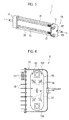
- a shell 21a that composes each of the shell tubes 21 includes a circumferential edge 35, beads (bulges) 39, and an inflow port 43 and an outflow port 47 that are provided upper and lower sides (near is both ends in a flow direction of the refrigerant), as shown in Figs. 4 and 6 .
- another shell 21b includes a circumferential edge 37, beads 41, an inflow port 45, and an outflow port 49.
- the circumferential edge 35 of the shell 21a is engaged with the circumferential edge 37 of the shell 21b.
- the inflow port 43 of the shell 21a is engaged with the inflow port 45 of the facing shell 21b.
- the outflow port 47 of the shell 21a is engaged with the outflow port 49 of the facing shell 21b.
- the inner fin 29 includes an inflow hole 51 corresponding to the inflow ports 43 and 45, an outflow hole 53 corresponding to the outflow ports 47 and 49, and multiple grooves 55 along the flow direction of the refrigerant.
- the grooves 55 are formed by processing the inner fin 29 corrugated.
- a pair of the shell 21a and 21b is engaged with each other at their circumferential edges 35 and 37 with interposing the inner fin 29 therebetween, so that an assembly (a unit) of the shell tube 21 is constructed.
- the plural shell tubes 21 are sequentially connected with each other at their inflow ports 43 and 45 and their outflow ports 47 and 49 with interposing the patches 31 therebetween.
- the beads 39 and 41 on the adjacent shell tubes 21 are contacted with each other.
- a constant proper load applies in a stacking direction of the shell tubes 21.
- the inflow port 45 and the outflow port 49 of the outermost shell 21b are sealed by the end patches 33. Each clearance of the gaps 25 is kept proper by the patches 31 and the beads 39 and 41.
- the water-cooled heat exchanger 19 is constructed by brazing these above-mentioned elements with each other.
- the inner fin 29 is brazed with the shells 21a and 21b at its top edges of the corrugated shape.
- the inflow port 43 of the innermost shell 21a is connected with a compressor in the cooling system 9 via an inlet port 57.
- the outflow port 47 of the innermost shell 21a is connected with the condenser 7 in the cooling system 9 via an outlet port 59.
- the coolant for the drive motor 3 and such is circulated by a pump 61, and flown into the upstream tank 11 as shown in Figs. 2 and 3 .
- the coolant is cooled by cooling air via the heat release fins 17 while flowing through the flat tubes 15, and then flown out from the downstream tank 13 to cool the drive motor 3 and such.
- the air-conditioning refrigerant in a high-temperature and high-temperature gas state that has been compressed by the compressor is flown into the shell tubes 21 of the water-cooled heat exchanger 19 from the inflow port 43 and 45, as shown in Fig. 5 .
- the refrigerant is cooled by the coolant flowing in the downstream tank 13 while flowing down along the grooves 55 of the inner fin 19.
- the cooled refrigerant becomes gas state where its superheat degree reduces or gas-fluid mixed state where it is partially saturated, and then is flown out from the outflow port 47 and 49. Further, the refrigerant flows down to the condenser 7 and is condensed.
- the refrigerant flown out from the condenser 7 is decompressed by a pressure reduction valve (not shown).
- the decompressed refrigerant is heat-changed in an evaporator (not shown).
- the refrigerant flown out from the evaporator is compressed by the compressor. Then, this cycle is repeated.
- the water-cooled heat exchanger 19 Since the water-cooled heat exchanger 19 is configured so as to flow the refrigerant from its upper side to its lower side and then flow out it therefrom, it is restrained that lubricating oil for the compressor that is mixed in the refrigerant stays at the lower side of the water-cooled heat exchanger 19. Further, since the lower end of the shell tube 21 is formed almost circularly rounded, the restraining effect of oil-staying improves. As a result, degradation of heat-exchange efficiency due to oil-staying, and degradation of performance and reliability of the cooling system 9 due to insufficient lubrication in the compressor are restrained.
- the water-cooled heat exchanger 19 is disposed in the downstream tank 13 for the coolant that has been cooled by cooling air, high heat-exchange efficiency can be brought.
- the refrigerant spreads in a width direction of the inner fin 29 along with this shape, as shown by arrows 63 in Fig. 4 .
- heat-exchange efficiency between the refrigerant and the coolant further improves.
- the combined heat exchanger 1 is configured extremely compact, and thereby exerts superior performance in its installation to a vehicle.
- the combined heat exchanger 1 is used in the cooling system 9 in a vehicle, and thereby can effectively cool heat generators such as the engine, the air-conditioner and the drive motor 3.
- an inner fin (refrigerant-passage unit) 101 fixed within the shell tube (refrigerant-passage unit) 21 is extended to circularly curved portions located at its both ends in the flow direction of the refrigerant.
- a pair of slits 103 extended from the inflow hole 51 is formed on both sides of the inflow hole 51.
- a pair of slits 105 extended from the outflow hole 53 is formed on both sides of the outflow hole 53.
- the inner fin 101 is brazed with the shell tube 21 at its top edges of the corrugated shape and at its both ends in the flow direction. Therefore, anti-pressure strength of tube is ensured to its both ends in the flow direction.
- the slits 103 and 105 are disposed to extend over some of the grooves 55.
- the refrigerant is spread (from the inflow hole 51: the slits 103) in an almost perpendicular direction (in the width direction) to its flow direction due to the slits 103 and 105, and then collected (to the slits 105: the outflow hole 53). Since the refrigerant flows in a full-width of the shell tube 21 due to slits 103 and 105, a contact area between the refrigerant and the coolant is expanded and thereby heat-exchange efficiency improves. In addition, since the slits 105 are inclined so as to lower their own sides communicating with the outflow hole 53, oil in the refrigerant is surely introduced into the outflow hole 53.
- an outer diameter r of the patch 31 is smaller than each outer diameter R of both ends 157 and 159 ( Fig. 4 ) of the shell tube 21.
- the slits 103 and 105 extend outward from an outer circumference of the patch 31.
- both the inflow hole 51 and the outflow hole 53 are disposed at a center on the inner fin 101 in its width direction, they may be disposed with offset in the width direction. In this case, the flow of the refrigerant can be further spread in the width direction. As a result, heat-exchange efficiency can further improve.
- a combined heat exchanger according to a third embodiment will be explained with reference to Figs. 9(a) and 9(b) .
- notches 153 and 155 are formed on the inner fin (refrigerant-passage unit) 151.
- the upper notch 153 is provided in the width direction along the end 157 ( Fig. 4 ) of the shell tube 21 on a side of the inflow ports 43 and 45.
- the lower notch 155 is provided in the width direction along the end 159 ( Fig. 4 ) of the shell tube 21 on a side of the outflow ports 47 and 49.
- the notches 153 and 155 are disposed to extend all of the grooves 55.
- the refrigerant is spread (from the inflow hole 51: the notch 153) in an almost perpendicular direction (in the width direction) to its flow direction due to the notches 153 and 155, and then collected (to the notch 155: the outflow hole 53). Since the refrigerant flows in a full-width of the shell tube 21 due to notches 153 and 155, a contact area between the refrigerant and the coolant is expanded and thereby heat-exchange efficiency improves.
- the inflow hole 51 and the outflow hole 53 may be disposed with offset in the width direction also on the inner fin 151.
- the flow of the refrigerant can be further spread in the width direction.
- heat-exchange efficiency can further improve.
Applications Claiming Priority (2)
| Application Number | Priority Date | Filing Date | Title |
|---|---|---|---|
| JP2008301312A JP2010127508A (ja) | 2008-11-26 | 2008-11-26 | 複合熱交換器 |
| PCT/JP2009/069779 WO2010061808A1 (fr) | 2008-11-26 | 2009-11-24 | Unité d'échange de chaleur composite |
Publications (1)
| Publication Number | Publication Date |
|---|---|
| EP2360444A1 true EP2360444A1 (fr) | 2011-08-24 |
Family
ID=42225683
Family Applications (1)
| Application Number | Title | Priority Date | Filing Date |
|---|---|---|---|
| EP09829056A Withdrawn EP2360444A1 (fr) | 2008-11-26 | 2009-11-24 | Unite d'echange de chaleur composite |
Country Status (5)
| Country | Link |
|---|---|
| US (1) | US20110232868A1 (fr) |
| EP (1) | EP2360444A1 (fr) |
| JP (1) | JP2010127508A (fr) |
| CN (1) | CN102224391A (fr) |
| WO (1) | WO2010061808A1 (fr) |
Cited By (1)
| Publication number | Priority date | Publication date | Assignee | Title |
|---|---|---|---|---|
| CN104919264A (zh) * | 2013-03-06 | 2015-09-16 | 康奈可关精株式会社 | 复合型热交换器 |
Families Citing this family (35)
| Publication number | Priority date | Publication date | Assignee | Title |
|---|---|---|---|---|
| DE102010013381A1 (de) * | 2010-03-30 | 2011-10-06 | Gm Global Technology Operations Llc (N.D.Ges.D. Staates Delaware) | Vorderbau für ein Kraftfahrzeug |
| JP5531901B2 (ja) * | 2010-10-08 | 2014-06-25 | カルソニックカンセイ株式会社 | 複合型熱交換器 |
| US20120297820A1 (en) | 2011-05-27 | 2012-11-29 | Akira Masuda | Combined heat exchanger system |
| JP2012245866A (ja) * | 2011-05-27 | 2012-12-13 | Calsonic Kansei Corp | 複合熱交換器 |
| JP5668610B2 (ja) | 2011-06-10 | 2015-02-12 | カルソニックカンセイ株式会社 | 水冷コンデンサ |
| CN102518501A (zh) * | 2011-11-30 | 2012-06-27 | 深圳市五洲龙汽车有限公司 | 混合动力汽车的发动机冷却系统 |
| JP5730237B2 (ja) * | 2012-03-30 | 2015-06-03 | カルソニックカンセイ株式会社 | 統合冷却システム |
| JP5730236B2 (ja) * | 2012-03-30 | 2015-06-03 | カルソニックカンセイ株式会社 | 統合冷却システム |
| CN104185770B (zh) * | 2012-03-30 | 2017-06-30 | 康奈可关精株式会社 | 综合冷却系统 |
| JP5730238B2 (ja) * | 2012-03-30 | 2015-06-03 | カルソニックカンセイ株式会社 | 統合冷却システム |
| JP5712974B2 (ja) * | 2012-07-05 | 2015-05-07 | カルソニックカンセイ株式会社 | 車両用熱交換装置 |
| JP5712972B2 (ja) * | 2012-06-28 | 2015-05-07 | カルソニックカンセイ株式会社 | 車両用熱交換装置 |
| JP5712973B2 (ja) * | 2012-06-28 | 2015-05-07 | カルソニックカンセイ株式会社 | 車両用熱交換装置 |
| JP5747879B2 (ja) * | 2012-08-01 | 2015-07-15 | カルソニックカンセイ株式会社 | 熱交換器 |
| KR101416369B1 (ko) | 2012-11-08 | 2014-07-08 | 현대자동차 주식회사 | 차량용 에어컨 시스템 |
| KR101490906B1 (ko) * | 2012-12-13 | 2015-02-06 | 현대자동차 주식회사 | 차량용 쿨링모듈 |
| KR101438608B1 (ko) * | 2012-12-13 | 2014-09-05 | 현대자동차 주식회사 | 차량용 쿨링모듈 |
| JP5985387B2 (ja) * | 2012-12-28 | 2016-09-06 | カルソニックカンセイ株式会社 | 複合型熱交換器 |
| CN103292624B (zh) * | 2013-05-08 | 2015-01-07 | 宁波汇富机电制造有限公司 | 一种风冷水冷双冷结构的高效换热器 |
| KR101405234B1 (ko) * | 2013-06-05 | 2014-06-10 | 현대자동차 주식회사 | 차량용 라디에이터 |
| DE102013114872B4 (de) * | 2013-06-07 | 2023-09-21 | Halla Visteon Climate Control Corp. | Kühler für Fahrzeug |
| JP2014238233A (ja) * | 2013-06-10 | 2014-12-18 | カルソニックカンセイ株式会社 | 複合型熱交換器 |
| JP5807660B2 (ja) * | 2013-06-07 | 2015-11-10 | カルソニックカンセイ株式会社 | 複合型熱交換器 |
| KR20140143650A (ko) * | 2013-06-07 | 2014-12-17 | 현대자동차주식회사 | 차량용 쿨링모듈 |
| KR101448790B1 (ko) * | 2013-09-27 | 2014-10-08 | 현대자동차 주식회사 | 차량용 히트펌프 시스템 |
| US20150101778A1 (en) * | 2013-10-14 | 2015-04-16 | Hyundai Motor Company | Cooling module for vehicle |
| KR101542978B1 (ko) * | 2013-12-12 | 2015-08-07 | 현대자동차 주식회사 | 차량용 쿨링모듈 |
| US9308800B2 (en) * | 2013-12-18 | 2016-04-12 | Hyundai Motor Company | Control method of air conditioner system for vehicle |
| US20170122666A1 (en) * | 2014-07-16 | 2017-05-04 | Hanon Systems | Integral heat exchanger |
| CN106132739B (zh) * | 2014-07-24 | 2018-10-23 | 翰昂汽车零部件有限公司 | 车辆用空调系统 |
| KR102170459B1 (ko) * | 2015-02-04 | 2020-10-29 | 한온시스템 주식회사 | 차량용 에어컨시스템 |
| KR102403512B1 (ko) | 2015-04-30 | 2022-05-31 | 삼성전자주식회사 | 공기 조화기의 실외기, 이에 적용되는 컨트롤 장치 |
| KR102255799B1 (ko) * | 2015-06-15 | 2021-05-26 | 한온시스템 주식회사 | 차량용 에어컨의 냉동 사이클 |
| KR102518597B1 (ko) * | 2018-10-30 | 2023-04-05 | 현대자동차 주식회사 | 차량용 쿨링모듈 |
| JP7388007B2 (ja) * | 2019-06-06 | 2023-11-29 | 株式会社デンソー | 熱交換器、冷凍サイクル装置 |
Family Cites Families (4)
| Publication number | Priority date | Publication date | Assignee | Title |
|---|---|---|---|---|
| JP2006162176A (ja) * | 2004-12-08 | 2006-06-22 | Mitsubishi Heavy Ind Ltd | 熱交換器および車両用空気調和装置 |
| JP2008039212A (ja) * | 2006-08-02 | 2008-02-21 | Calsonic Kansei Corp | 熱交換器 |
| WO2008072730A1 (fr) * | 2006-12-14 | 2008-06-19 | Calsonic Kansei Corporation | Échangeur de chaleur complexe et échangeur de chaleur |
| JP2008170140A (ja) * | 2006-12-14 | 2008-07-24 | Calsonic Kansei Corp | 車両用熱交換器 |
-
2008
- 2008-11-26 JP JP2008301312A patent/JP2010127508A/ja not_active Withdrawn
-
2009
- 2009-11-24 EP EP09829056A patent/EP2360444A1/fr not_active Withdrawn
- 2009-11-24 US US13/131,187 patent/US20110232868A1/en not_active Abandoned
- 2009-11-24 WO PCT/JP2009/069779 patent/WO2010061808A1/fr active Application Filing
- 2009-11-24 CN CN2009801472933A patent/CN102224391A/zh active Pending
Non-Patent Citations (1)
| Title |
|---|
| See references of WO2010061808A1 * |
Cited By (1)
| Publication number | Priority date | Publication date | Assignee | Title |
|---|---|---|---|---|
| CN104919264A (zh) * | 2013-03-06 | 2015-09-16 | 康奈可关精株式会社 | 复合型热交换器 |
Also Published As
| Publication number | Publication date |
|---|---|
| WO2010061808A1 (fr) | 2010-06-03 |
| US20110232868A1 (en) | 2011-09-29 |
| JP2010127508A (ja) | 2010-06-10 |
| CN102224391A (zh) | 2011-10-19 |
Similar Documents
| Publication | Publication Date | Title |
|---|---|---|
| EP2360444A1 (fr) | Unite d'echange de chaleur composite | |
| US10753686B2 (en) | Condenser for vehicle | |
| JP5184314B2 (ja) | 冷却システム | |
| JP2008126720A (ja) | クーリングモジュール | |
| US20100175863A1 (en) | Heat Exchange Insert For A Heat-Exchange Device | |
| US20170299270A1 (en) | Cooling module | |
| EP1998133A1 (fr) | Echangeur de chaleur et echangeur de chaleur de type integre | |
| JP2008180486A (ja) | 熱交換器 | |
| KR101438608B1 (ko) | 차량용 쿨링모듈 | |
| WO2008072730A1 (fr) | Échangeur de chaleur complexe et échangeur de chaleur | |
| US6772602B2 (en) | Cooling system for a vehicle | |
| WO2014097977A1 (fr) | Échangeur de chaleur combiné | |
| WO2018230529A1 (fr) | Échangeur de chaleur | |
| WO2020170651A1 (fr) | Échangeur de chaleur composé | |
| KR102439432B1 (ko) | 차량용 쿨링모듈 | |
| US9551534B2 (en) | Heat exchanger assembly having a seal | |
| US20090249810A1 (en) | Evaporator | |
| CN101995116A (zh) | 蒸发器 | |
| JP2004239598A (ja) | 熱交換器 | |
| KR101490906B1 (ko) | 차량용 쿨링모듈 | |
| JP4276893B2 (ja) | 車両用熱交換装置 | |
| JP2014126315A (ja) | 複合型熱交換器 | |
| JP2012245866A (ja) | 複合熱交換器 | |
| JP2010018151A (ja) | 車両用熱交換器 | |
| JP2004077114A (ja) | 一体型熱交換装置 |
Legal Events
| Date | Code | Title | Description |
|---|---|---|---|
| PUAI | Public reference made under article 153(3) epc to a published international application that has entered the european phase |
Free format text: ORIGINAL CODE: 0009012 |
|
| 17P | Request for examination filed |
Effective date: 20110621 |
|
| AK | Designated contracting states |
Kind code of ref document: A1 Designated state(s): AT BE BG CH CY CZ DE DK EE ES FI FR GB GR HR HU IE IS IT LI LT LU LV MC MK MT NL NO PL PT RO SE SI SK SM TR |
|
| DAX | Request for extension of the european patent (deleted) | ||
| STAA | Information on the status of an ep patent application or granted ep patent |
Free format text: STATUS: THE APPLICATION HAS BEEN WITHDRAWN |
|
| 18W | Application withdrawn |
Effective date: 20121123 |