EP2360407A1 - Vorrichtung zum Verbinden einer Leitung an einen Flansch - Google Patents
Vorrichtung zum Verbinden einer Leitung an einen Flansch Download PDFInfo
- Publication number
- EP2360407A1 EP2360407A1 EP11000524A EP11000524A EP2360407A1 EP 2360407 A1 EP2360407 A1 EP 2360407A1 EP 11000524 A EP11000524 A EP 11000524A EP 11000524 A EP11000524 A EP 11000524A EP 2360407 A1 EP2360407 A1 EP 2360407A1
- Authority
- EP
- European Patent Office
- Prior art keywords
- flange
- line
- tie rods
- head
- spreading
- Prior art date
- Legal status (The legal status is an assumption and is not a legal conclusion. Google has not performed a legal analysis and makes no representation as to the accuracy of the status listed.)
- Granted
Links
- 125000006850 spacer group Chemical group 0.000 abstract 1
- 238000010276 construction Methods 0.000 description 1
Images

Classifications
-
- F—MECHANICAL ENGINEERING; LIGHTING; HEATING; WEAPONS; BLASTING
- F16—ENGINEERING ELEMENTS AND UNITS; GENERAL MEASURES FOR PRODUCING AND MAINTAINING EFFECTIVE FUNCTIONING OF MACHINES OR INSTALLATIONS; THERMAL INSULATION IN GENERAL
- F16L—PIPES; JOINTS OR FITTINGS FOR PIPES; SUPPORTS FOR PIPES, CABLES OR PROTECTIVE TUBING; MEANS FOR THERMAL INSULATION IN GENERAL
- F16L23/00—Flanged joints
- F16L23/02—Flanged joints the flanges being connected by members tensioned axially
- F16L23/036—Flanged joints the flanges being connected by members tensioned axially characterised by the tensioning members, e.g. specially adapted bolts or C-clamps
-
- F—MECHANICAL ENGINEERING; LIGHTING; HEATING; WEAPONS; BLASTING
- F16—ENGINEERING ELEMENTS AND UNITS; GENERAL MEASURES FOR PRODUCING AND MAINTAINING EFFECTIVE FUNCTIONING OF MACHINES OR INSTALLATIONS; THERMAL INSULATION IN GENERAL
- F16L—PIPES; JOINTS OR FITTINGS FOR PIPES; SUPPORTS FOR PIPES, CABLES OR PROTECTIVE TUBING; MEANS FOR THERMAL INSULATION IN GENERAL
- F16L23/00—Flanged joints
- F16L23/003—Auxiliary devices
-
- F—MECHANICAL ENGINEERING; LIGHTING; HEATING; WEAPONS; BLASTING
- F16—ENGINEERING ELEMENTS AND UNITS; GENERAL MEASURES FOR PRODUCING AND MAINTAINING EFFECTIVE FUNCTIONING OF MACHINES OR INSTALLATIONS; THERMAL INSULATION IN GENERAL
- F16L—PIPES; JOINTS OR FITTINGS FOR PIPES; SUPPORTS FOR PIPES, CABLES OR PROTECTIVE TUBING; MEANS FOR THERMAL INSULATION IN GENERAL
- F16L23/00—Flanged joints
- F16L23/006—Attachments
-
- F—MECHANICAL ENGINEERING; LIGHTING; HEATING; WEAPONS; BLASTING
- F16—ENGINEERING ELEMENTS AND UNITS; GENERAL MEASURES FOR PRODUCING AND MAINTAINING EFFECTIVE FUNCTIONING OF MACHINES OR INSTALLATIONS; THERMAL INSULATION IN GENERAL
- F16L—PIPES; JOINTS OR FITTINGS FOR PIPES; SUPPORTS FOR PIPES, CABLES OR PROTECTIVE TUBING; MEANS FOR THERMAL INSULATION IN GENERAL
- F16L23/00—Flanged joints
- F16L23/02—Flanged joints the flanges being connected by members tensioned axially
- F16L23/032—Flanged joints the flanges being connected by members tensioned axially characterised by the shape or composition of the flanges
-
- F—MECHANICAL ENGINEERING; LIGHTING; HEATING; WEAPONS; BLASTING
- F16—ENGINEERING ELEMENTS AND UNITS; GENERAL MEASURES FOR PRODUCING AND MAINTAINING EFFECTIVE FUNCTIONING OF MACHINES OR INSTALLATIONS; THERMAL INSULATION IN GENERAL
- F16L—PIPES; JOINTS OR FITTINGS FOR PIPES; SUPPORTS FOR PIPES, CABLES OR PROTECTIVE TUBING; MEANS FOR THERMAL INSULATION IN GENERAL
- F16L37/00—Couplings of the quick-acting type
- F16L37/62—Couplings of the quick-acting type pneumatically or hydraulically actuated
Definitions
- the invention relates to a device for short-term connection of a first line to the flange of a second line, in particular as part of a hydraulic test stand, wherein the flange of the second line has bores.
- the object of the invention is to provide a device by which a short-term connection of lines with little time and effort and with sufficient tightness is possible.
- a clamping system which allows a secure connection and re-release quickly and with minimal effort.
- the construction is simple and of small dimensions.
- a compact structurally simple and safe device is provided when it has a surrounding the interior of coaxial annulus, in which the tie rods extend and are secured therein in or on actuators by which the tie rods are moved longitudinally.
- the arranged in the annulus actuating devices may have hydraulic or pneumatic clamping cylinder.
- the spreader heads each have a spreader ring with ring sectors on the side facing away from the head end, the inner surface of which tapers conically towards the top end.
- a correspondingly shaped cone can be inserted within the expansion ring, which sits at the end of a tube surrounding the pull rod, which protrudes immovably on the device, in particular on the actuating device.
- a second line 2 in particular a pressure booster to be tested, is securely attached to the first line, not shown by screws 3 and has an annular body 4 with a cylindrical outer wall 5 and a cylindrical coaxial interior 6.
- Hier the interior 6 as a cavity makes a connection between the two lines.
- the ring body 4 of the device 1 has on both sides annular coaxial side surfaces 7, 8, wherein from the side surface 7, the screws 3 emerge to be fastened to the flange of the first conduit.
- On the opposite side surface 8 pull rods 9 parallel to the axis, which are aligned with holes 10 in the flange 11 of the second line to pass through them.
- the device 1 forms between the cylindrical outer wall 5 and the inner space 6 an annular space 12 into which the tie rods 9 extend and can be actuated by clamping cylinders in their longitudinal direction, which are referred to below as "actuating devices" 13.
- actuating devices By these hydraulically or pneumatically driven actuators 13, the tie rods 9 are displaceable in its longitudinal direction in both directions.
- each spreading head 14 On the second line 2 facing ends of the tie rods 9 each have a spreading head 14 is fixed, which has an outer diameter in the unexpanded state, which is slightly smaller than the inner diameter of the holes 10 in the flange 11 of the second line 2.
- Each spreading head 14 points to the the actuating device 13 facing the end of a spreader 16, which is divided by axially parallel longitudinal column 18 in ring sectors 17, wherein the ring sectors 17 have a conically tapering towards the head inner surface 19 which rest on a cone 20.
- the cone 20 is formed at the end of a tube 21 coaxially surrounds the pull rod 9 and is guided into the interior 6 and fixed to the actuator 13 or to the device 1.
- the cone 20 is immobile and by pulling on the pull rod 9 to the actuator 13 towards the ring sectors 17 are spread by the cone 20 so far that its outer diameter is greater than the inner diameter of the bore 10, so that the ring sectors 17 at the outer edge of the bore 10 rest when the pull rod 9 is moved in the direction of the device 1 out.
- the flange 11 of the second line 2 is pressed against the side surface 8 of the device 1.
- a line in this case the second line 2
- the second line with its flange 11 only needs to be brought to the device so far that the tension rods 9 with their spreading heads 14 are the holes 10 of the flange 11 penetrate.
- the clamping cylinder of the devices 13 are actuated hydraulically or pneumatically and by the retracting a few millimeters drawbar 9 in the device 1, the spreading heads 14 are extended by the cone 20 and lie against the edges of the holes 10 and at a further train to the Rods 9, the flange 11 of the second line securely to the device 1 and its side surface 8 is used.
- a release of the second line is effected by moving the tie rods 9 in the reverse direction by the actuators 13th
Landscapes
- Engineering & Computer Science (AREA)
- General Engineering & Computer Science (AREA)
- Mechanical Engineering (AREA)
- Investigating Strength Of Materials By Application Of Mechanical Stress (AREA)
- Clamps And Clips (AREA)
Abstract
Description
- Die Erfindung betrifft eine Vorrichtung zum kurzzeitigen Verbinden einer ersten Leitung an den Flansch einer zweiten Leitung insbesondere als Teil eines hydraulischen Prüfstandes, wobei der Flansch der zweiten Leitung Bohrungen aufweist.
- Es ist häufig erforderlich, zwei Leitungen kurzzeitig miteinander zu verbinden. So müssen beim Prüfen von Druckerhöhungsanlagen die Saugleitung und die Druckleitung an die Leitungen der Prüfvorrichtung angeschlossen werden. Dies geschieht bisher durch das Aneinanderschrauben von Flanschen, so dass ein erheblicher Arbeits- und Zeitaufwand erforderlich ist.
- Aufgabe der Erfindung ist es, eine Vorrichtung zu schaffen, durch die ein kurzzeitiges Verbinden von Leitungen bei geringem Zeit- und Arbeitsaufwand und bei ausreichender Dichtheit ermöglicht wird.
- Diese Aufgabe wird erfindungsgemäß dadurch gelöst,
- dass die Vorrichtung am Ende der ersten Leitung befestigt ist und einen Innenraum als Verlängerung der ersten Leitung bildet,
- dass an der Vorrichtung in Richtung des Flansches der zweiten Leitung achsparallel Zugstangen vorstehen, deren Achsen mit den Bohrungsachsen fluchten,
- dass die Zugstangen an ihrem Stangenende jeweils einen Spreizkopf tragen, dessen Außendurchmesser im umgespreizten Zustand geringer ist als der Innendurchmesser der Bohrungen, und
- dass nach dem Durchstecken der Spreizköpfe durch die Bohrungen durch Zug an den Zugstangen die Spreizköpfe erweitert werden, um den Bohrungsrand zu übergreifen und den Flansch dichtend an die Vorrichtung heranzuziehen.
- Hierdurch wird ein Spannsystem geschaffen, das ein sicheres Anschließen und ein wieder Lösen schnell und bei geringstem Arbeitsaufwand ermöglicht. Hierbei ist die Konstruktion einfach und von geringen Abmessungen.
- Eine kompakte konstruktiv einfache und sichere Vorrichtung wird geschaffen, wenn sie einen den Innenraum umgebenden koaxialen Ringraum aufweist, in den die Zugstangen hineinreichen und dort in oder an Betätigungsvorrichtungen befestigt sind, durch die die Zugstangen längs bewegt werden.
- Hierbei können die im Ringraum angeordneten Betätigungsvorrichtungen hydraulische oder pneumatische Spannzylinder aufweisen.
- Besonders vorteilhaft ist es, wenn die Spreizköpfe auf der dem Kopfende abgewandten Seite jeweils einen Spreizring mit Ringsektoren aufweisen, dessen Innenfläche sich zum Kopfende hin konisch verjüngt. Hierbei kann innerhalb des Spreizringes ein entsprechend geformter Konus einliegen, der am Ende eines die Zugstange umgebenden Rohres sitzt, das unbeweglich an der Vorrichtung insbesondere an der Betätigungsvorrichtung vorsteht.
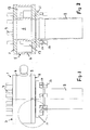
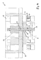
- Ein Ausführungsbeispiel der Erfindung ist in den Zeichnungen dargestellt und wird im Folgenden näher beschrieben. Es zeigen
- Fig. 1
- eine Seitenansicht der Vorrichtung, befestigt an der zweiten Leitung,
- Fig. 2
- einen axialen Schnitt durch die Vorrichtung nach
Fig. 1 , - Fig. 3
- eine perspektivische Ansicht der Vorrichtung nach
Fig. 1 und 2 , - Fig. 4
- einen Längsschnitt durch die Vorrichtung in Höhe des Spannzylinders.
- Die Vorrichtung (Spannvorrichtung) 1 zum kurzzeitigen Befestigen einer ersten Leitung, z. B. der Leitung eines Prüfstandes, an einer zweiten Leitung 2, insbesondere einer zu testenden Druckerhöhungsanlage, ist an der nicht dargestellten ersten Leitung durch Schrauben 3 sicher befestigt und weist einen Ringkörper 4 auf mit einer zylindrischen Außenwand 5 und einem zylindrischen koaxialen Innenraum 6. Hierbei stellt der Innenraum 6 als Hohlraum eine Verbindung zwischen beiden Leitungen her.
- Der Ringkörper 4 der Vorrichtung 1 weist auf beiden Seiten ringförmige koaxiale Seitenflächen 7, 8 auf, wobei aus der Seitenfläche 7 die Schrauben 3 austreten, um an den Flansch der ersten Leitung befestigt zu werden. Auf der gegenüberliegenden Seitenfläche 8 treten Zugstangen 9 achsparallel aus, die mit Bohrungen 10 im Flansch 11 der zweiten Leitung fluchten, um durch diese hindurchtreten zu können.
- Die Vorrichtung 1 bildet zwischen der zylindrischen Außenwand 5 und dem Innenraum 6 einen Ringraum 12, in den die Zugstangen 9 hineinreichen und von Spannzylindern in ihrer Längsrichtung betätigbar sind, die im Folgenden "Betätigungsvorrichtungen" 13 genannt werden. Durch diese hydraulisch oder pneumatisch angetriebenen Betätigungsvorrichtungen 13 sind die Zugstangen 9 in ihrer Längsrichtung in beide Richtungen verschieblich.
- Auf den der zweiten Leitung 2 zugewandten Enden der Zugstangen 9 ist jeweils ein Spreizkopf 14 befestigt, der im ungespreizten Zustand einen Außendurchmesser aufweist, der geringfügig kleiner ist als der Innendurchmesser der Bohrungen 10 im Flansch 11 der zweiten Leitung 2. Jeder Spreizkopf 14 weist an dem der Betätigungsvorrichtung 13 zugewandten Ende einen Spreizring 16 auf, der durch achsparallele Längsspalte 18 in Ringsektoren 17 aufgeteilt ist, wobei die Ringsektoren 17 eine sich zum Kopfende hin konisch verjüngende Innenfläche 19 aufweisen, die auf einem Konus 20 aufliegen.
- Der Konus 20 ist am Ende eines Rohres 21 angeformt, das koaxial die Zugstange 9 umgibt und bis in den Innenraum 6 geführt und an der Betätigungsvorrichtung 13 oder an der Vorrichtung 1 befestigt ist. Damit ist der Konus 20 unbeweglich und durch einen Zug an der Zugstange 9 zur Betätigungsvorrichtung 13 hin werden die Ringsektoren 17 durch den Konus 20 soweit aufgespreizt, dass ihr Außendurchmesser größer ist als der Innendurchmesser der Bohrung 10, so dass die Ringsektoren 17 am Außenrand der Bohrung 10 aufliegen, wenn die Zugstange 9 in Richtung der Vorrichtung 1 hin verschoben wird. Hierdurch wird der Flansch 11 der zweiten Leitung 2 gegen die Seitenfläche 8 der Vorrichtung 1 gedrückt.
- Soll eine Leitung, in diesem Fall die zweite Leitung 2, an der Vorrichtung 1 befestigt werden, so braucht die zweite Leitung mit ihrem Flansch 11 nur soweit an die Vorrichtung herangeführt zu werden, dass die Zugstangen 9 mit ihren Spreizköpfen 14 die Bohrungen 10 des Flansches 11 durchdringen. Danach werden die Spannzylinder der Vorrichtungen 13 hydraulisch oder pneumatisch betätigt und durch die um wenige Millimeter einfahrende Zugstange 9 in die Vorrichtung 1 werden die Spreizköpfe 14 durch den Konus 20 erweitert und legen sich an die Ränder der Bohrungen 10 an und bei einem weiteren Zug an den Stangen 9 wird der Flansch 11 der zweiten Leitung sicher an die Vorrichtung 1 bzw. deren Seitenfläche 8 herangezogen. Ein Lösen der zweiten Leitung erfolgt durch ein Bewegen der Zugstangen 9 in umgekehrter Richtung durch die Betätigungsvorrichtungen 13.
Claims (5)
- Vorrichtung (1) zum kurzzeitigen Verbinden einer ersten Leitung an den Flansch (11) einer zweiten Leitung (2) insbesondere als Teil eines hydraulischen Prüfstandes, wobei der Flansch (11) der zweiten Leitung Bohrungen (10) aufweist, dadurch gekennzeichnet,- dass die Vorrichtung (1) am Ende der ersten Leitung befestigt ist und einen Innenraum (6) als Verlängerung der ersten Leitung bildet,- dass an der Vorrichtung (1) in Richtung des Flansches (11) der zweiten Leitung (2) achsparallel Zugstangen (9) vorstehen, deren Achsen mit den Bohrungsachsen fluchten,- dass die Zugstangen (9) an ihrem Stangenende jeweils einen Spreizkopf (14) tragen, dessen Außendurchmesser im umgespreizten Zustand geringer ist als der Innendurchmesser der Bohrungen (10), und- dass nach dem Durchstecken der Spreizköpfe (14) durch die Bohrungen (10) durch Zug an den Zugstangen (9) die Spreizköpfe erweitert werden, um den Bohrungsrand zu übergreifen und den Flansch (11) dichtend an die Vorrichtung (1) heranzuziehen.
- Vorrichtung nach Anspruch 1,dadurch gekennzeichnet, dass sie einen den Innenraum (6) umgebenden koaxialen Ringraum (12) aufweist, in den die Zugstangen (9) hineinreichen und dort in oder an Betätigungsvorrichtungen (13) befestigt sind, durch die die Zugstangen längs bewegt werden.
- Vorrichtung nach Anspruch 2, dadurch gekennzeichnet, dass die im Ringraum (12) angeordneten Betätigungsvorrichtungen (13) hydraulische oder pneumatische Spannzylinder aufweisen.
- Vorrichtung nach einem der vorherigen Ansprüche, dadurch gekennzeichnet, dass die Spreizköpfe (14) auf der dem Kopfende abgewandten Seite jeweils einen Spreizring (16) mit Ringsektoren (17) aufweisen, dessen Innenfläche sich zum Kopfende hin konisch verjüngt.
- Vorrichtung nach Anspruch 4, dadurch gekennzeichnet, dass innerhalb des Spreizringes (16) ein entsprechend geformter Konus (20) einliegt, der am Ende eines die Zugstange (9) umgebenden Rohres (21) sitzt, das unbeweglich an der Vorrichtung (1) insbesondere an der Betätigungsvorrichtung (13) vorsteht.
Applications Claiming Priority (1)
| Application Number | Priority Date | Filing Date | Title |
|---|---|---|---|
| DE201010008432 DE102010008432A1 (de) | 2010-02-18 | 2010-02-18 | Vorrichtung zum Verbinden einer Leitung an einen Flansch |
Publications (2)
| Publication Number | Publication Date |
|---|---|
| EP2360407A1 true EP2360407A1 (de) | 2011-08-24 |
| EP2360407B1 EP2360407B1 (de) | 2012-06-06 |
Family
ID=43896651
Family Applications (1)
| Application Number | Title | Priority Date | Filing Date |
|---|---|---|---|
| EP20110000524 Active EP2360407B1 (de) | 2010-02-18 | 2011-01-24 | Vorrichtung zum Verbinden einer Leitung an einen Flansch |
Country Status (2)
| Country | Link |
|---|---|
| EP (1) | EP2360407B1 (de) |
| DE (1) | DE102010008432A1 (de) |
Citations (2)
| Publication number | Priority date | Publication date | Assignee | Title |
|---|---|---|---|---|
| WO2007003937A1 (en) * | 2005-07-02 | 2007-01-11 | Equalizer International Limited | Apparatus and method for separating flanges |
| DE102008022172A1 (de) * | 2008-05-05 | 2009-11-12 | Endress + Hauser Flowtec Ag | Vorrichtung zur Herstellung einer Verbindung zwischen einem Messgerät und einer Rohrleitung |
Family Cites Families (2)
| Publication number | Priority date | Publication date | Assignee | Title |
|---|---|---|---|---|
| DD281231A5 (de) * | 1989-04-11 | 1990-08-01 | Berlin Energiekombinat | Verfahren und vorrichtung zum aufspreizen bzw. zum zusammendruecken von flanschverbindungen in rohrleitungen |
| US6467811B2 (en) * | 2000-08-10 | 2002-10-22 | Omega Multi National | Flanged connection repair device and method |
-
2010
- 2010-02-18 DE DE201010008432 patent/DE102010008432A1/de not_active Withdrawn
-
2011
- 2011-01-24 EP EP20110000524 patent/EP2360407B1/de active Active
Patent Citations (2)
| Publication number | Priority date | Publication date | Assignee | Title |
|---|---|---|---|---|
| WO2007003937A1 (en) * | 2005-07-02 | 2007-01-11 | Equalizer International Limited | Apparatus and method for separating flanges |
| DE102008022172A1 (de) * | 2008-05-05 | 2009-11-12 | Endress + Hauser Flowtec Ag | Vorrichtung zur Herstellung einer Verbindung zwischen einem Messgerät und einer Rohrleitung |
Also Published As
| Publication number | Publication date |
|---|---|
| EP2360407B1 (de) | 2012-06-06 |
| DE102010008432A1 (de) | 2011-08-18 |
Similar Documents
| Publication | Publication Date | Title |
|---|---|---|
| EP1998097B1 (de) | Rohrkupplung, Verfahren zum Rohrkuppeln, und zur Selbstreinigung von Kupplungshälften beim Rohrkuppeln | |
| DE3850549T2 (de) | Schlauchkupplung. | |
| EP0333094A1 (de) | Lösbare Verbindungsvorrichtung für Rohre, Schläuche, Stangen oder dergleichen | |
| DE19653745B4 (de) | Schnellkupplung | |
| EP2924322B1 (de) | Dichtungsvorrichtung | |
| DE2635269A1 (de) | Vorrichtung zum verbinden der enden zweier rohre | |
| DE2122638A1 (de) | Verbindung zwischen zwei Rohrelementen | |
| DE3009168C2 (de) | Vorrichtung zum Druckprüfen von Schlauchleitungen mit Metallarmaturen | |
| DE3923579A1 (de) | Anschlussarmatur fuer rohre, insbesondere fuer kunststoffrohre | |
| EP2062689A1 (de) | Rohrverbindungsvorrichtung | |
| EP2360407B1 (de) | Vorrichtung zum Verbinden einer Leitung an einen Flansch | |
| DE29700886U1 (de) | Vorrichtung zum Zentrieren oder Positionieren von Blechen, vornehmlich zur Verwendung im Karosseriebau der Kfz-Industrie | |
| EP3939726A1 (de) | Innenspannmittel zum spannen einer mehrzahl von werkstücken | |
| DE19747250C1 (de) | Verbindungsstück zum Einziehen von Rohrleitungen | |
| DE102018101163B4 (de) | Rohrkupplungssystem | |
| DE202010012173U1 (de) | Molchstation | |
| DE102012003146A1 (de) | Schlauchverbindung und Verfahren zur Herstellung einer Schlauchverbindung | |
| DE102020101262B4 (de) | Kupplungseinrichtung zum Verbinden von hydraulischen Leitungen und Prüfsystem mit einer Kupplungseinrichtung | |
| DE102015204799A1 (de) | Dichtungsvorrichtung | |
| WO2018115405A1 (de) | Verfahren und werkzeug zur demontage eines filterelements aus einer rohrleitung | |
| DE10139038C2 (de) | Vorrichtung und Verfahren zum Einspannen eines Anschlußteils | |
| EP2182259A1 (de) | Verfahren zum Sperren einer Rohrleitung und Rohrsperrgerät | |
| DE102012025139A1 (de) | Fluid-Schnellkupplungsvorrichtung | |
| WO2010020652A1 (de) | Einsteckkupplung für rohre | |
| DE3608463A1 (de) | Steckkupplung |
Legal Events
| Date | Code | Title | Description |
|---|---|---|---|
| PUAI | Public reference made under article 153(3) epc to a published international application that has entered the european phase |
Free format text: ORIGINAL CODE: 0009012 |
|
| 17P | Request for examination filed |
Effective date: 20110616 |
|
| AK | Designated contracting states |
Kind code of ref document: A1 Designated state(s): AL AT BE BG CH CY CZ DE DK EE ES FI FR GB GR HR HU IE IS IT LI LT LU LV MC MK MT NL NO PL PT RO RS SE SI SK SM TR |
|
| AX | Request for extension of the european patent |
Extension state: BA ME |
|
| RIC1 | Information provided on ipc code assigned before grant |
Ipc: F16L 23/028 20060101ALI20111219BHEP Ipc: F16L 23/032 20060101ALI20111219BHEP Ipc: F16L 23/036 20060101ALI20111219BHEP Ipc: F16L 23/02 20060101ALI20111219BHEP Ipc: F16L 23/00 20060101AFI20111219BHEP Ipc: F16L 37/62 20060101ALI20111219BHEP |
|
| GRAP | Despatch of communication of intention to grant a patent |
Free format text: ORIGINAL CODE: EPIDOSNIGR1 |
|
| GRAS | Grant fee paid |
Free format text: ORIGINAL CODE: EPIDOSNIGR3 |
|
| GRAA | (expected) grant |
Free format text: ORIGINAL CODE: 0009210 |
|
| AK | Designated contracting states |
Kind code of ref document: B1 Designated state(s): AL AT BE BG CH CY CZ DE DK EE ES FI FR GB GR HR HU IE IS IT LI LT LU LV MC MK MT NL NO PL PT RO RS SE SI SK SM TR |
|
| REG | Reference to a national code |
Ref country code: GB Ref legal event code: FG4D Free format text: NOT ENGLISH |
|
| REG | Reference to a national code |
Ref country code: AT Ref legal event code: REF Ref document number: 561213 Country of ref document: AT Kind code of ref document: T Effective date: 20120615 Ref country code: CH Ref legal event code: EP |
|
| REG | Reference to a national code |
Ref country code: IE Ref legal event code: FG4D Free format text: LANGUAGE OF EP DOCUMENT: GERMAN |
|
| REG | Reference to a national code |
Ref country code: DE Ref legal event code: R096 Ref document number: 502011000035 Country of ref document: DE Effective date: 20120802 |
|
| REG | Reference to a national code |
Ref country code: NL Ref legal event code: VDEP Effective date: 20120606 |
|
| PG25 | Lapsed in a contracting state [announced via postgrant information from national office to epo] |
Ref country code: NO Free format text: LAPSE BECAUSE OF FAILURE TO SUBMIT A TRANSLATION OF THE DESCRIPTION OR TO PAY THE FEE WITHIN THE PRESCRIBED TIME-LIMIT Effective date: 20120906 Ref country code: FI Free format text: LAPSE BECAUSE OF FAILURE TO SUBMIT A TRANSLATION OF THE DESCRIPTION OR TO PAY THE FEE WITHIN THE PRESCRIBED TIME-LIMIT Effective date: 20120606 Ref country code: CY Free format text: LAPSE BECAUSE OF FAILURE TO SUBMIT A TRANSLATION OF THE DESCRIPTION OR TO PAY THE FEE WITHIN THE PRESCRIBED TIME-LIMIT Effective date: 20120606 Ref country code: RS Free format text: LAPSE BECAUSE OF FAILURE TO SUBMIT A TRANSLATION OF THE DESCRIPTION OR TO PAY THE FEE WITHIN THE PRESCRIBED TIME-LIMIT Effective date: 20120606 Ref country code: SE Free format text: LAPSE BECAUSE OF FAILURE TO SUBMIT A TRANSLATION OF THE DESCRIPTION OR TO PAY THE FEE WITHIN THE PRESCRIBED TIME-LIMIT Effective date: 20120606 Ref country code: LT Free format text: LAPSE BECAUSE OF FAILURE TO SUBMIT A TRANSLATION OF THE DESCRIPTION OR TO PAY THE FEE WITHIN THE PRESCRIBED TIME-LIMIT Effective date: 20120606 |
|
| REG | Reference to a national code |
Ref country code: LT Ref legal event code: MG4D Effective date: 20120606 |
|
| PG25 | Lapsed in a contracting state [announced via postgrant information from national office to epo] |
Ref country code: HR Free format text: LAPSE BECAUSE OF FAILURE TO SUBMIT A TRANSLATION OF THE DESCRIPTION OR TO PAY THE FEE WITHIN THE PRESCRIBED TIME-LIMIT Effective date: 20120606 Ref country code: LV Free format text: LAPSE BECAUSE OF FAILURE TO SUBMIT A TRANSLATION OF THE DESCRIPTION OR TO PAY THE FEE WITHIN THE PRESCRIBED TIME-LIMIT Effective date: 20120606 Ref country code: SI Free format text: LAPSE BECAUSE OF FAILURE TO SUBMIT A TRANSLATION OF THE DESCRIPTION OR TO PAY THE FEE WITHIN THE PRESCRIBED TIME-LIMIT Effective date: 20120606 Ref country code: GR Free format text: LAPSE BECAUSE OF FAILURE TO SUBMIT A TRANSLATION OF THE DESCRIPTION OR TO PAY THE FEE WITHIN THE PRESCRIBED TIME-LIMIT Effective date: 20120907 |
|
| PG25 | Lapsed in a contracting state [announced via postgrant information from national office to epo] |
Ref country code: RO Free format text: LAPSE BECAUSE OF FAILURE TO SUBMIT A TRANSLATION OF THE DESCRIPTION OR TO PAY THE FEE WITHIN THE PRESCRIBED TIME-LIMIT Effective date: 20120606 Ref country code: CZ Free format text: LAPSE BECAUSE OF FAILURE TO SUBMIT A TRANSLATION OF THE DESCRIPTION OR TO PAY THE FEE WITHIN THE PRESCRIBED TIME-LIMIT Effective date: 20120606 Ref country code: IS Free format text: LAPSE BECAUSE OF FAILURE TO SUBMIT A TRANSLATION OF THE DESCRIPTION OR TO PAY THE FEE WITHIN THE PRESCRIBED TIME-LIMIT Effective date: 20121006 Ref country code: NL Free format text: LAPSE BECAUSE OF FAILURE TO SUBMIT A TRANSLATION OF THE DESCRIPTION OR TO PAY THE FEE WITHIN THE PRESCRIBED TIME-LIMIT Effective date: 20120606 Ref country code: SK Free format text: LAPSE BECAUSE OF FAILURE TO SUBMIT A TRANSLATION OF THE DESCRIPTION OR TO PAY THE FEE WITHIN THE PRESCRIBED TIME-LIMIT Effective date: 20120606 Ref country code: EE Free format text: LAPSE BECAUSE OF FAILURE TO SUBMIT A TRANSLATION OF THE DESCRIPTION OR TO PAY THE FEE WITHIN THE PRESCRIBED TIME-LIMIT Effective date: 20120606 |
|
| PG25 | Lapsed in a contracting state [announced via postgrant information from national office to epo] |
Ref country code: PT Free format text: LAPSE BECAUSE OF FAILURE TO SUBMIT A TRANSLATION OF THE DESCRIPTION OR TO PAY THE FEE WITHIN THE PRESCRIBED TIME-LIMIT Effective date: 20121008 Ref country code: PL Free format text: LAPSE BECAUSE OF FAILURE TO SUBMIT A TRANSLATION OF THE DESCRIPTION OR TO PAY THE FEE WITHIN THE PRESCRIBED TIME-LIMIT Effective date: 20120606 |
|
| PLBE | No opposition filed within time limit |
Free format text: ORIGINAL CODE: 0009261 |
|
| STAA | Information on the status of an ep patent application or granted ep patent |
Free format text: STATUS: NO OPPOSITION FILED WITHIN TIME LIMIT |
|
| PG25 | Lapsed in a contracting state [announced via postgrant information from national office to epo] |
Ref country code: DK Free format text: LAPSE BECAUSE OF FAILURE TO SUBMIT A TRANSLATION OF THE DESCRIPTION OR TO PAY THE FEE WITHIN THE PRESCRIBED TIME-LIMIT Effective date: 20120606 |
|
| 26N | No opposition filed |
Effective date: 20130307 |
|
| REG | Reference to a national code |
Ref country code: DE Ref legal event code: R097 Ref document number: 502011000035 Country of ref document: DE Effective date: 20130307 |
|
| BERE | Be: lapsed |
Owner name: WILO SE Effective date: 20130131 |
|
| PG25 | Lapsed in a contracting state [announced via postgrant information from national office to epo] |
Ref country code: BG Free format text: LAPSE BECAUSE OF FAILURE TO SUBMIT A TRANSLATION OF THE DESCRIPTION OR TO PAY THE FEE WITHIN THE PRESCRIBED TIME-LIMIT Effective date: 20120906 |
|
| PG25 | Lapsed in a contracting state [announced via postgrant information from national office to epo] |
Ref country code: MC Free format text: LAPSE BECAUSE OF NON-PAYMENT OF DUE FEES Effective date: 20130131 |
|
| REG | Reference to a national code |
Ref country code: IE Ref legal event code: MM4A |
|
| PG25 | Lapsed in a contracting state [announced via postgrant information from national office to epo] |
Ref country code: ES Free format text: LAPSE BECAUSE OF FAILURE TO SUBMIT A TRANSLATION OF THE DESCRIPTION OR TO PAY THE FEE WITHIN THE PRESCRIBED TIME-LIMIT Effective date: 20120917 Ref country code: BE Free format text: LAPSE BECAUSE OF NON-PAYMENT OF DUE FEES Effective date: 20130131 |
|
| PG25 | Lapsed in a contracting state [announced via postgrant information from national office to epo] |
Ref country code: AL Free format text: LAPSE BECAUSE OF FAILURE TO SUBMIT A TRANSLATION OF THE DESCRIPTION OR TO PAY THE FEE WITHIN THE PRESCRIBED TIME-LIMIT Effective date: 20120606 Ref country code: IE Free format text: LAPSE BECAUSE OF NON-PAYMENT OF DUE FEES Effective date: 20130124 |
|
| PG25 | Lapsed in a contracting state [announced via postgrant information from national office to epo] |
Ref country code: MT Free format text: LAPSE BECAUSE OF FAILURE TO SUBMIT A TRANSLATION OF THE DESCRIPTION OR TO PAY THE FEE WITHIN THE PRESCRIBED TIME-LIMIT Effective date: 20120606 |
|
| REG | Reference to a national code |
Ref country code: CH Ref legal event code: PL |
|
| PG25 | Lapsed in a contracting state [announced via postgrant information from national office to epo] |
Ref country code: LI Free format text: LAPSE BECAUSE OF NON-PAYMENT OF DUE FEES Effective date: 20140131 Ref country code: CH Free format text: LAPSE BECAUSE OF NON-PAYMENT OF DUE FEES Effective date: 20140131 |
|
| PG25 | Lapsed in a contracting state [announced via postgrant information from national office to epo] |
Ref country code: SM Free format text: LAPSE BECAUSE OF FAILURE TO SUBMIT A TRANSLATION OF THE DESCRIPTION OR TO PAY THE FEE WITHIN THE PRESCRIBED TIME-LIMIT Effective date: 20120606 |
|
| PG25 | Lapsed in a contracting state [announced via postgrant information from national office to epo] |
Ref country code: TR Free format text: LAPSE BECAUSE OF FAILURE TO SUBMIT A TRANSLATION OF THE DESCRIPTION OR TO PAY THE FEE WITHIN THE PRESCRIBED TIME-LIMIT Effective date: 20120606 |
|
| PG25 | Lapsed in a contracting state [announced via postgrant information from national office to epo] |
Ref country code: LU Free format text: LAPSE BECAUSE OF NON-PAYMENT OF DUE FEES Effective date: 20130124 Ref country code: MK Free format text: LAPSE BECAUSE OF FAILURE TO SUBMIT A TRANSLATION OF THE DESCRIPTION OR TO PAY THE FEE WITHIN THE PRESCRIBED TIME-LIMIT Effective date: 20120606 Ref country code: HU Free format text: LAPSE BECAUSE OF FAILURE TO SUBMIT A TRANSLATION OF THE DESCRIPTION OR TO PAY THE FEE WITHIN THE PRESCRIBED TIME-LIMIT; INVALID AB INITIO Effective date: 20110124 |
|
| REG | Reference to a national code |
Ref country code: FR Ref legal event code: PLFP Year of fee payment: 6 |
|
| REG | Reference to a national code |
Ref country code: FR Ref legal event code: PLFP Year of fee payment: 7 |
|
| PGFP | Annual fee paid to national office [announced via postgrant information from national office to epo] |
Ref country code: GB Payment date: 20161228 Year of fee payment: 7 |
|
| REG | Reference to a national code |
Ref country code: AT Ref legal event code: MM01 Ref document number: 561213 Country of ref document: AT Kind code of ref document: T Effective date: 20160124 |
|
| PG25 | Lapsed in a contracting state [announced via postgrant information from national office to epo] |
Ref country code: AT Free format text: LAPSE BECAUSE OF NON-PAYMENT OF DUE FEES Effective date: 20160124 |
|
| PGFP | Annual fee paid to national office [announced via postgrant information from national office to epo] |
Ref country code: IT Payment date: 20170103 Year of fee payment: 7 |
|
| REG | Reference to a national code |
Ref country code: FR Ref legal event code: PLFP Year of fee payment: 8 |
|
| GBPC | Gb: european patent ceased through non-payment of renewal fee |
Effective date: 20180124 |
|
| PG25 | Lapsed in a contracting state [announced via postgrant information from national office to epo] |
Ref country code: GB Free format text: LAPSE BECAUSE OF NON-PAYMENT OF DUE FEES Effective date: 20180124 |
|
| PG25 | Lapsed in a contracting state [announced via postgrant information from national office to epo] |
Ref country code: IT Free format text: LAPSE BECAUSE OF NON-PAYMENT OF DUE FEES Effective date: 20180124 |
|
| PGFP | Annual fee paid to national office [announced via postgrant information from national office to epo] |
Ref country code: FR Payment date: 20221220 Year of fee payment: 13 |
|
| P01 | Opt-out of the competence of the unified patent court (upc) registered |
Effective date: 20230615 |
|
| REG | Reference to a national code |
Ref country code: DE Ref legal event code: R084 Ref document number: 502011000035 Country of ref document: DE |
|
| PG25 | Lapsed in a contracting state [announced via postgrant information from national office to epo] |
Ref country code: FR Free format text: LAPSE BECAUSE OF NON-PAYMENT OF DUE FEES Effective date: 20240131 |
|
| PG25 | Lapsed in a contracting state [announced via postgrant information from national office to epo] |
Ref country code: FR Free format text: LAPSE BECAUSE OF NON-PAYMENT OF DUE FEES Effective date: 20240131 |
|
| PGFP | Annual fee paid to national office [announced via postgrant information from national office to epo] |
Ref country code: DE Payment date: 20241218 Year of fee payment: 15 |