EP2359944A2 - Selbstangetriebener Sieb - Google Patents
Selbstangetriebener Sieb Download PDFInfo
- Publication number
- EP2359944A2 EP2359944A2 EP11153539A EP11153539A EP2359944A2 EP 2359944 A2 EP2359944 A2 EP 2359944A2 EP 11153539 A EP11153539 A EP 11153539A EP 11153539 A EP11153539 A EP 11153539A EP 2359944 A2 EP2359944 A2 EP 2359944A2
- Authority
- EP
- European Patent Office
- Prior art keywords
- screening device
- frame
- conveyor
- locking arm
- self
- Prior art date
- Legal status (The legal status is an assumption and is not a legal conclusion. Google has not performed a legal analysis and makes no representation as to the accuracy of the status listed.)
- Withdrawn
Links
- 238000012216 screening Methods 0.000 claims abstract description 394
- 239000000463 material Substances 0.000 claims abstract description 39
- 238000001514 detection method Methods 0.000 claims description 10
- 238000010276 construction Methods 0.000 description 15
- 238000010586 diagram Methods 0.000 description 12
- 238000012423 maintenance Methods 0.000 description 6
- 230000007246 mechanism Effects 0.000 description 5
- 238000003466 welding Methods 0.000 description 5
- 239000000470 constituent Substances 0.000 description 3
- 208000019901 Anxiety disease Diseases 0.000 description 2
- 230000036506 anxiety Effects 0.000 description 2
- 230000007423 decrease Effects 0.000 description 2
- 239000010720 hydraulic oil Substances 0.000 description 2
- 238000004519 manufacturing process Methods 0.000 description 2
- 238000000034 method Methods 0.000 description 2
- 230000002093 peripheral effect Effects 0.000 description 2
- 230000002265 prevention Effects 0.000 description 2
- 230000008439 repair process Effects 0.000 description 2
- 230000000452 restraining effect Effects 0.000 description 2
- 230000007480 spreading Effects 0.000 description 2
- 238000003892 spreading Methods 0.000 description 2
- 230000001629 suppression Effects 0.000 description 2
- 229910000831 Steel Inorganic materials 0.000 description 1
- 230000008859 change Effects 0.000 description 1
- 238000004140 cleaning Methods 0.000 description 1
- 230000008878 coupling Effects 0.000 description 1
- 238000010168 coupling process Methods 0.000 description 1
- 238000005859 coupling reaction Methods 0.000 description 1
- 238000007599 discharging Methods 0.000 description 1
- 230000000694 effects Effects 0.000 description 1
- 230000005484 gravity Effects 0.000 description 1
- 238000003780 insertion Methods 0.000 description 1
- 230000037431 insertion Effects 0.000 description 1
- 230000002452 interceptive effect Effects 0.000 description 1
- 238000010030 laminating Methods 0.000 description 1
- 238000012545 processing Methods 0.000 description 1
- 238000004064 recycling Methods 0.000 description 1
- 238000006748 scratching Methods 0.000 description 1
- 230000002393 scratching effect Effects 0.000 description 1
- 239000010959 steel Substances 0.000 description 1
Images


Classifications
-
- B—PERFORMING OPERATIONS; TRANSPORTING
- B07—SEPARATING SOLIDS FROM SOLIDS; SORTING
- B07B—SEPARATING SOLIDS FROM SOLIDS BY SIEVING, SCREENING, SIFTING OR BY USING GAS CURRENTS; SEPARATING BY OTHER DRY METHODS APPLICABLE TO BULK MATERIAL, e.g. LOOSE ARTICLES FIT TO BE HANDLED LIKE BULK MATERIAL
- B07B1/00—Sieving, screening, sifting, or sorting solid materials using networks, gratings, grids, or the like
- B07B1/005—Transportable screening plants
Definitions
- the present invention relates to a self-propelled screen for sorting materials according to grain size.
- Vibrating screens are devices that vibrate a screening device, that is, a frame with a screening member mounted therein, and then selectively separate loaded materials into two groups, one smaller than the screening grain size at the screening member side, and the other larger than the screening grain size.
- a vibrating screen of this type for example, if the inclination angle of the screening device to the horizontal increases, the moving rate of the materials on the screening member also increases during screening. This increase correspondingly shortens the dwell time of the materials on the screening member, increasing throughput (screening volume) per unit time. Conversely, decreases in the inclination angle of the screening device give more chances for the materials to collide against the screening member, and correspondingly improve screening accuracy.
- JP,A-307503 introduces a self-propelled screen that includes a screening device tiltably coupled to a frame provided above a truck body and makes adjustable an inclination angle of a vibrating screen according to properties of materials to be screened, screening grain size, and/or other parameters.
- a prior application relating to a self-propelled screen that includes, in addition to a conveyor coupled tiltably with respect to a truck body, a screening device installed above the conveyor, thereby to make the conveyor and the screening device integrally tilt with respect to the truck body.
- tilting the conveyor allows an inclination angle of the screening device to be changed and a clearance between the screening device and the conveyor to be kept constant, independently of the inclination angle of the screening device.
- Vibrating screens are often equipped with a plurality of tiers of screening members, inclusive of the top deck as upper tier that uses a screening element relatively rough in screening grain size, and the bottom deck as lower tier that uses a screening element relatively fine in screening grain size.
- lack of a sufficient operator access space as the clearance between a screening device and a conveyor does not allow an operator to access the bottom deck in order to perform maintenance operations such as cleaning, while the invariant clearance between the screening device and conveyor in that arrangement is maintained.
- the operator needs to perform very troublesome disassembly tasks such as removing the top deck from the screening device or removing the screening device itself from the conveyor.
- An object of the invention is therefore to provide a self-propelled screen designed so as to make it possible to maintain a constant clearance between a screening device and a conveyor independently of an inclination angle of the screening device, and so as to enable easy access to a bottom deck of the screening device and hence improve maintainability.
- a self-propelled screen for sorting materials according to grain size includes: a truck device; a body frame provided substantially above the truck device; a conveyor tiltably coupled to the body frame; a screening device coupled tiltably relative to a frame of the conveyor so as to be positioned above the conveyor; a screen angle changing cylinder coupled at one end thereof to the body frame and at another end to the conveyor frame, the cylinder tilting the screening device as well as the conveyor; and a screening device opening/closing cylinder coupled at one end thereof to a screening device frame of the screening device and at another end to the conveyor frame, the cylinder tilting the screening device.
- a self-propelled screen based on the first aspect of the invention further includes: a support member provided on the screening device frame; and a hopper supported by the support member so as to be positioned above the screening device, the support member serving as a stiffening material for the screening device frame as well as working with the screening device frame to constitute a three-dimensional frame.
- a self-propelled screen based on the first aspect of the invention further includes a guide member provided on at least one (e.g., the screening device frame) of mutually opposed sections of the screening device frame and the conveyor frame so as to spread towards the other opposed section (e.g., the conveyor frame), the guide member guiding tilt operation of the screening device in a direction of closing with respect to the conveyor frame.
- a guide member provided on at least one (e.g., the screening device frame) of mutually opposed sections of the screening device frame and the conveyor frame so as to spread towards the other opposed section (e.g., the conveyor frame), the guide member guiding tilt operation of the screening device in a direction of closing with respect to the conveyor frame.
- a self-propelled screen based on the first aspect of the invention further includes: a locking arm provided pivotably with respect to the screening device frame; a bracket provided on the conveyor frame; and a pin for fixing a distal end of the locking arm to the bracket, the locking arm being constructed so that as the screening device tilts in a direction of opening with respect to the conveyor frame, the arm turns downward under its own weight, and so that upon the screening device reaching a defined angle of opening, a pin hole at the distal end of the arm is positioned at a pin hole of the bracket.
- a self-propelled screen based on the first aspect of the invention further includes: a sensor for detecting whether the screening device frame is in a closed state with respect to the conveyor frame; and a control unit for permitting the truck device and the screening device to operate, only if, on the basis of a detection signal from the sensor, the screening device frame is determined to be in the closed state.
- a self-propelled screen based on the first aspect of the invention is constructed so that the screening device opening/closing cylinder tilts upward or downward a rear side of the screening device to create a space between a proximal end of the conveyor and the screening device, and a step is provided at a rear-end side of the body frame.
- a self-propelled screen based on the first aspect of the invention further includes: a locking arm suspended from a lower section of the screening device frame so as to turnably operate in longitudinal direction of the locking arm; a lock pin provided at a distal end of the locking arm; and a locking block provided on the conveyor frame, the locking block including a securing section to secure the locking pin, wherein, as the screening device opening/closing cylinder is extended and the screening device is tilted upward, the locking arm extends lengthwise under its own weight from a retracted state between the screening device frame and the conveyor frame, next as the screening device opening/closing cylinder is further extended to its defined length, the lock pin provided on the locking arm rides over the securing section of the locking block, and then as the screening device opening/closing cylinder is retracted from the defined length, the lock pin hooks into the securing section, whereby the lock pin is then restrained.
- the locking block in the seventh aspect of the invention has a stopper to limit a lengthwise extending range of the locking arm so as to prevent this arm from turning beyond its vertical position relative to the conveyor frame.
- the lock pin in the seventh aspect of the invention is always supported by the locking block independently of a position or posture of the screening device, and the locking arm in the seventh aspect is always spaced from the conveyor frame supporting the locking block.
- the locking block in the ninth aspect of the invention has an upper face at which is present a guide member that guides the lock pin during the extension and retraction of the locking arm.
- the lock pin in the seventh aspect of the invention is insertable into and removable from the locking arm
- the locking block in the seventh aspect includes an auxiliary securing section formed so that even if the lock pin is not mounted in the locking arm, the securing section secures the screening device opening/closing cylinder to the distal end of the locking arm when the cylinder is retracted from the defined length.
- a constant clearance is maintained between a screening device and a conveyor independently of an inclination angle of the screening device, and easy access to a bottom deck of the screening device is achieved, which in turn improves maintainability.
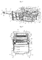
- Fig. 1 is a side view illustrating an overall configuration of a self-propelled screen according to a first embodiment of the present invention
- Fig. 2 is a rear view of the screen as viewed from the right side of Fig. 1 .
- the left and right of Fig. 1 is referred to as the front and rear of the self-propelled screen
- the left and right of Fig. 2 as the left and right of the screen.
- the present embodiment is described below taking an example of applying the present invention to a screening device of double-floor construction with a top deck and a bottom deck, the invention can also be applied to screening devices of single-floor construction or triple-floor construction or of construction with more floors.
- the self-propelled screen shown in Figs. 1 and 2 includes a truck body 1, a discharge conveyor 2 provided above the truck body 1, a screening device 3 provided above the discharge conveyor 2, and a power pack 4 provided under the discharge conveyor 2.
- the truck body 1 includes one pair of left and right truck devices 10, and a body frame 11 provided at an upper section of the truck devices 10.
- the truck devices 10 include one pair of left and right truck frames 12, driven wheels 13 and driving wheels 14 provided at front and rear positions, respectively, of the truck frames 12, hydraulic traveling motors 15 each with an output shaft coupled to one of the driving wheels 14, and crawlers 16 mounted over the left and right driven wheels 13 and driving wheels 14.
- the body frame 11, a frame-shaped member three-dimensionally built using a plurality of steel plates extending in vertical, horizontal, and longitudinal directions, is provided above the truck frames 12, and has a front end positioned posterior to a front end of each truck device 10 so that the front end of the body frame 11 stays behind that of the truck device 10.
- the body frame 11 has a rear end positioned slightly posterior to a rear end of the truck device 10.
- a guard 17 for preventing materials from interfering with a rear end of the discharge conveyor 2 is provided at the rear of the body frame 11.
- the discharge conveyor 2 is designed to carry, of all materials that have been sorted by the screening device 3, only those of a predetermined grain size or less and discharge the carried materials from the front of the machine body.
- the discharge conveyor 2 is disposed so as to raise its front end obliquely.
- Fig. 1 shows a transport posture that assumes transport of the machine body by trailer truck or the like, so the discharge conveyor 2 is small in angle of inclination to a ground level.
- the inclination angle of the discharge conveyor 2 can be increased using a screen angle changing cylinder 38 (to be described later). The angle of inclination can also be adjusted for control of processing efficiency.
- the discharge conveyor 2 includes a conveyor frame 20, a head pulley 21 pivotably provided at a front end of the conveyor frame 20, a tail pulley (not shown) that is pivotably provided at a rear end of the conveyor frame 20, a conveyor belt 23 mounted over the head pulley 21 and the tail pulley, and a discharge conveyor hydraulic motor 24 coupled to the head pulley 21.
- the discharge conveyor hydraulic motor 24 drives the head pulley 21, thus driving the conveyor belt 23 to circularly move between the head pulley 21 and the tail pulley.
- the conveyor frame 20 is coupled at its rear end to an upper rear-end portion of the body frame 11 via a pivotal shaft 30 so as to be tiltable towards this upper rear-end portion, and is supported at a longitudinal middle section of the frame 20 via a support member 31 by the body frame 11.
- the support member 31 includes a tubular casing 32 and a rod 33 inserted into this casing.
- An upper end of the casing 32 is pivotably coupled to a bracket 35 provided centrally on a longitudinal section of the conveyor frame 20 via a pin 34, and a lower end of the rod 33 is pivotably coupled to a bracket 37 provided on a front section of the body frame 11 via a pin 36.
- the casing 32 and rod 33 of the support member 31 are coupled to each other by the screen angle changing cylinder 38, and as this screen angle changing cylinder 38 telescopically moves, the rod 33 slides relative to the casing 32. This sliding movement consequently tilts the discharge conveyor 2 using the pivotal shaft 30 as a fulcrum.
- the casing 32 and the rod 33 both having a plurality of pin holes (not shown) that are lined up in extending and retracting directions of the rod 33, are constructed so that during the above sliding movement, changing an extension rate of the rod 33 and then selectively inserting pins (not shown) into the pin holes allow the support member 31 to be fixed at one of multiple length levels and the screening device 3 to be mechanically fixed at a stepwise adjustable angle position.
- the screening device 3 sorts out the materials loaded, according to grain size.
- the screening device 3 includes a screening device frame 44 positioned above a rear half of the conveyor frame 20, a frame form of screening device body 46 (vibrating element) supported by the screening device frame 44 via a resilient or elastic member 45 so as to be able to vibrate, a screening member 47 (see Fig. 2 ) fixed to the inside of the screening device body 46, and an exciter 48 for physically exciting the screening device body 46.
- the screening device 3 shakes the screening device body 46 and the screening member 47 together by driving the exciter 48 to guide, of all materials loaded for screening, only the materials of a predetermined grain size or less that pass through the screening member 47, to the surface of the discharge conveyor 2.
- the discharge conveyor 2 discharges the materials of greater grain sizes from the rear of the machine body.
- the screening device 3 in the present embodiment is of double-floor construction with the screening member 47 disposed on each of two vertical stages.
- the screening members 47 on the upper and lower stages are hereinafter termed the top deck and the bottom deck, respectively, as appropriate.
- the present embodiment uses a three-in-one type of coil spring as the resilient or elastic member 45
- this member can instead be a rubber spring or any other appropriate resilient or elastic element.
- the resilient or elastic member 45 is disposed at front and rear positions, each on both left and right sides, in the screening device body 46, and the screening device body 46 is supported in four places in all with respect to the conveyor frame 20. While three resilient or elastic members 45 are arranged in one place, the number of resilient or elastic members 45 per place is not limited to this layout form.
- the screening member 47 inside the screening device 3 is disposed so that the screening member 47 decreases in height at it goes closer to a rear end of the screening device 3, as with the discharge conveyor 2. Since the screening device 3 is supported by the conveyor frame 20 of the discharge conveyor 2, tilting the discharge conveyor 2, as described above, enables the angle of inclination to be changed according to properties of the materials to be screened, and thus, screening capabilities to be adjusted.
- the power pack 4 contains a motive power supply for the operating units mounted in various places on the machine body, such as an engine, hydraulic pumps, and control valves, and is disposed below the discharge conveyor 2, on a power pack frame 50 suspended from the conveyor frame 20.
- the power pack frame 50 is suspended from the conveyor frame 20 at a position closer to the front end of the discharge conveyor 2 than the bracket 35 connecting the support member 31, and the power pack 4 is also positioned ahead of the truck body 1.
- the discharge conveyor 2 is inclined by retracting the screen angle changing cylinder 38, the power pack 4 moves downward to a space in front of the truck body 1 without overlapping the truck body 1. This makes it possible to lay the discharge conveyor 2 nearly to a horizontal position, and hence to suppress overall machine height to a level within the transport height limits applied to transport on general roads.
- the power pack 4 can be installed on or above the body frame 11 or the truck frame 12.
- An operating unit 52 for specifying the above-described telescopic operation of the screen angle changing cylinder 38 is provided adjacently to the operator panel 51.
- the power pack 4 also has a stepped section (not shown) that serves as a platform for the operator to stand on for purposes such as operating the operator panel 51 and the operating unit 52.
- a scattering prevention cover 55 for receiving any materials that may scattering and fall from a return surface of the conveyor belt 23 during screening is provided under the discharge conveyor 2. Coverage of the scattering prevention cover 55 ranges at least above the power pack 4, and the cover 55 has its lower end and vicinity bent downward in a backward direction to actively guide received materials to a desired accumulating position (e.g., the ground surface between the left and right truck devices 10).
- a desired accumulating position e.g., the ground surface between the left and right truck devices 10
- the screening device 3 is coupled to the conveyor frame 20 in tiltable fashion relative thereto so as to be positioned above the discharge conveyor 2. More specifically, the screening device frame 44 is coupled at its front end to a bracket 61 in a longitudinally central section of the body frame 11 so as to be tiltable relative to the bracket 61 via a pivotal shaft 62. In addition, the screening device frame 44 has a rear section constructed so that a pad 63 at the rear end of the screening device frame 44 is supported by a mounting bracket 64, in a seated condition thereupon, near the rear end of the conveyor frame 20. A posture of the screening device 3 under such a state is hereinafter referred to as the closed posture or position as appropriate.
- the mounting bracket 64 of the conveyor frame 20 is coupled to the screening device frame 44 by a screening device opening/closing cylinder 65.
- the screening device opening/closing cylinder 65 As the screening device opening/closing cylinder 65 is extended or retracted, the screening device 3 therefore tilts in the supported condition with the pivotal shaft 62 as a fulcrum, this tilting operation spreading or narrowing the clearance between the conveyor frame 20 and the screening device frame 44.
- a posture of the screening device 3 having its rear half uptilted in the supported condition with the pivotal shaft 62 as the fulcrum, is hereinafter referred to as the open posture or position as appropriate.
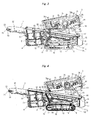
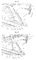
- Fig. 3 illustrates such a state of the self-propelled screen.
- Fig. 4 is a side view of the self-propelled screen from which a part of the screen shown in Fig. 3 is removed
- Fig. 5 is a perspective view of a neighboring structure of the screening device opening/closing cylinder 65 as viewed from a rear-left quarter.
- the screening device frame 44 includes a longitudinally extending frame 66 and two covers 67, one internally and one externally to the frame 66, in a lateral direction of the machine body.
- the screening device frame 44 is therefore constructed to form a longitudinally extending plate-like framework as a whole, and is located to each of the left and right of the screening device 3.
- Fig. 4 illustrates the self-propelled screen from which the outer cover 67 of the screening device frame 44 is removed.
- the pad 63 is mounted on a rear-end lower surface of the frame 66. More specifically, the pad 63 is provided on both left and right sides of the machine body, with an appropriate number of shims 60 interposed between the pad 63 and the frame 66. This ensures that the pads 63 on the left and right sides become simultaneously seated on related mounting brackets 64, that is, minimizes single-side contact relative to the brackets 64. Briefly, consideration is given so that single-side contact of the pads 43 on the left and right of the machine body can be suppressed by adjusting the shims 60 in thickness and the number of shims 60.
- the pads 63 each include a downward protruding guide member 59, and when the pad 63 becomes seated on the appropriate mounting bracket 64, the guide member 59 is inserted between two plates constituting the mounting bracket 64.
- the thus-inserted guide members 59 guide a shift of the screening device 3 to the closed posture, thus restraining a lateral movement of the screening device 3, and ensuring its stable seating position.
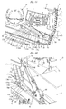
- flared guide members 68 are provided at a lower section of the screening device frame 44 so as to be positioned closer to the front end of the discharge conveyor 2 than the mounting brackets 64, at the rear half side of the screening device 3.
- the guide members 68 in the present embodiment are partial downward extensions of the inner and outer covers 67, the guide member 68 of the inner cover 67 being inclined downward in an inward direction relative to the machine body, and the guide member 68 of the outer cover 67 being inclined downward in an outward direction relative to the machine body.
- the guide members 68 may be provided at the conveyor frame side or provided on at least one (e.g., the screening device frame 44) of mutually opposed sections of the screening device frame 44 and the conveyor frame 20 so as to spread towards the other opposed section (e.g., the conveyor frame 20).
- the screening device opening/closing cylinder 65 has a rod end coupled to the inner and outer covers 67 via a pin 69, and a bottom end coupled to the mounting brackets 64 via a pin 70.
- a pin 72 at a fulcrum of a locking arm 71 and the pin 69 at the rod side of the screening device opening/closing cylinder 65 would be replaceable by one common pin.
- a locking mechanism for holding the screening device 3 mechanically in its opening position when the screening device opening/closing cylinder 65 is extended to shift the screening device 3 to the open posture is provided on both left and right sides of the machine body.
- This locking mechanism includes the locking arm 71 provided under the screening device frame 44, and a bracket 73 provided on the conveyor frame 20.
- the locking arm 71 positioned slightly in front of the pin 69 at the rod side of the screening device opening/closing cylinder 65, is coupled at one end to the screening device frame 44 by the pin 72, and is pivotable with the pin 72 as a fulcrum in a longitudinally extending vertical plane.
- the bracket 73 is provided on the conveyor frame 20 so as to be positioned below the pin 72.
- the bracket 73 is constructed so that as the screening device 3 tilts in its opening direction relative to the conveyor frame 20 and thus the locking arm 71 turns downward under its own weight, the screening device 3 reaches a defined opening angle, whereby a pin hole at a distal end (other end) of the locking arm 71 is positioned at a pin hole of the bracket 73.
- the distal end of the locking arm 71 is positioned at the bracket 73, the distal end of the locking arm 71 is fixed to the pin hole of the bracket 73 by threading a fixing pin 74 into the pin hole of the distal end of the locking arm 71 and the pin hole of the bracket 73.
- the pin 72 at the fulcrum of the locking arm 71 and the pin 69 at the rod side of the screening device opening/closing cylinder 65 can be replaced by one common pin.
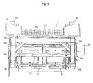
- Fig. 6 is a front view of the screening device as viewed from slightly above in front.
- a hopper 75 for guiding to the top deck of the screening device 3 the materials to be screened is provided at an upper section of the screening device 3.
- the hopper 75 is a chute-shaped member constructed by laminating a plurality of upward spreading plates, and has plates in three places, namely, a front plate, a left side plate, and a right side plate.
- the left and right side plates cover a region roughly ranging from the front end of the screening device 3 to a section slightly behind a longitudinally central section of the screening device 3.
- the hopper 75 is supported on the screening device frame 44 via a support member 76. As shown in Fig.
- the support member 76 includes vertical frames 76a extending vertically at four corners, horizontal frames 76b arranged longitudinally across the vertical frames 76a, a horizontal frame 76c disposed laterally across two front ones of the vertical frames 76a, and oblique frames 76d arranged obliquely between two forward extending upper ones of the horizontal frames 76b and the front left and right vertical frames 76a.
- the support member 76 serves as a stiffening member for the screening device frame 44.
- the hopper 75 is installed on the forward extending horizontal frames 76b and above the remaining horizontal frame 76b.
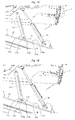
- Figs. 7 and 8 are side views of the screening device front end and vicinity as viewed from the right side of the machine body, Fig. 7 illustrating a closed state of the screening device frame 44 relative to the conveyor frame 20, and Fig. 8 illustrating an open state of the screening device frame 44 relative to the conveyor frame 20.
- the present embodiment further includes a sensor 81 that detects whether the screening device frame 44 is in the closed state relative to the conveyor frame 20, that is, whether the screening device 3 is in the closing position.
- the sensor 81 can be a limit switch, a proximity switch, or any other appropriate detector. A proximity switch is used in the present embodiment.
- the screening device frame 44 in contrast, includes a member 82 to be detected.
- the member 82 to be detected is mounted on a side face of the screening device frame 44 so as to extend downward.
- a detection signal from the sensor 81 is output to a control unit (not shown), which permits the truck devices 10 and the screening device 3 to operate, only if the control unit determines from the output detection signal of the sensor 81 that the screening device frame 44 is closed relative to the conveyor frame 20.
- the control unit determines from the output detection signal of the sensor 81 that the screening device frame 44 is closed relative to the conveyor frame 20.
- the control unit also permits operation of machine elements, inclusive of the truck devices 10, screening device 3, discharge conveyor 2, etc., but except for the cylinders 38 and 65.
- the control unit determines from this signal state that the screening device frame 44 is open relative to the conveyor frame 20, and then prohibits the operation of the truck devices 10, screening device 3, discharge conveyor 2, etc., but except for the cylinders 38 and 65.
- the control unit includes an interlock.
- the sensor 81 in the present example is disposed at a section slightly behind the pivotal shaft 62 of the screening device 3, on the right-side face of the conveyor frame 20, the disposition of the sensor 81 is not limited to this position and may be on the left-side face of the conveyor frame 20 or the layout of the sensor 81 and the pivotal shaft 62 may be changed as appropriate. Further alternatively, the sensor 81 would be provided on the screening device frame 44, not on the conveyor frame 20. Moreover, the member 82 to be detected may be omitted if the sensor 81 can be provided at a position that enables direct detection of the screening device frame 44 or the conveyor frame 20.
- a possible alternative way to detect whether the screening device frame 44 is in the closed state with respect to the conveyor frame 20 is by, for example, mounting a potentiometer on the pivotal shaft 62 of the screening device 3 and using this potentiometer to detect the inclination angle of the screening device 3 with respect to the discharge conveyor 2.
- the self-propelled screen may have an optional side conveyor to discharge from a side face of the machine body the materials that move along the surface of the top deck and are discharged sideways.
- a side conveyor for discharging from a side face of the machine body the materials that move along the surface of the bottom deck and are discharged sideways may be further installed so that the materials divided into three types according to grain size will be discharged in three different directions.
- the screening device 3 can be tilted by extending/retracting the screen angle changing cylinder 38 to adjust screening performance of the screening device 3.
- the screening device 3 tilts with the discharge conveyor 2, a positional relationship between the screening device 3 and the discharge conveyor 2 remains undisturbed, regardless of the inclination angle of the screening device 3, so the tilting motion of the screening device 3 basically does not facilitate scattering of any materials passed through the screening member 47.
- the screening device 3 can be tilted with respect to the discharge conveyor 2 (only the screening device 3 can be tilted independently of the discharge conveyor 2), an open space can be created between the conveyor frame 20 and the screening device frame 44 by extending the screening device opening/closing cylinder 65.
- the operator can easily access the bottom deck from the discharge conveyor 2 by leaving the space between the conveyor frame 20 and the screening device frame 44 open, without removing the top deck or removing the screening device 3 from the discharge conveyor 2.
- the clearance between the discharge conveyor 2 and the screening device 3 can be kept constant independently of the inclination angle of the screening device 3, and access to the bottom deck of the screening device 3 can be facilitated. Additionally, since the bottom deck is accessible from the discharge conveyor side, this access method, unlike accessing from the top deck side, eliminates any need for the operator to mount a high place on the machine, and makes the operator feel secure in this context.
- the screening device opening/closing cylinder 65 moves the rear side of the screening device 3 vertically to create a space between a proximal-end side of the discharge conveyor 2 and the screening device 3, at a rear side of the body frame 11.
- steps 18 are provided on the guard 17, at the rear side of the body frame 11 where the space is created by an uptilt and downslant of the rear side of the screening device 3. If the screening device 3 should ever be constructed so that its front side moves vertically, as the upward inclination angle of the discharge conveyor 2 increases at its front end, the space created by the tilting motion of the screening device 3 would also be higher in position.
- the screening device 3 whose height becomes smaller towards the rear end of the screening device is constructed to move vertically at the rear side, the space between the screening device 3 and the discharge conveyor 2 can be created at a fixed position, which allows a working burden of the operator to be reduced and his/her anxiety about overhead work to be alleviated.
- the steps 18 provided at appropriate places are useful for access to the space.
- the machine since the machine has an overall shape that diminishes machine height towards the rear end of the machine body, the machine rear is lower than sides and the front, the construction of which makes it easier for the operator to mount the machine rear than the sides and the front.
- the screening device 3 tilts independently of the discharge conveyor 2 and one of the longitudinal ends of the screening device 3 serves as a fulcrum. Unless sufficient stiffness is given to the screening device 3, uptilting the screening device 3 could distort sections such as the screening device 3 and/or its frame, and should the distortion actually happen, the screening device 3 might not return to its original position, even when later tilted downward.
- the support members 76 for the hopper 75 strengthen the screening device frame 44 to establish a three-dimensional framework (in the present embodiment, truss construction) and hence to ensure sufficient stiffness of the screening device 3.
- the guide members 68, 59 reliably guide the screening device 3 to its original posture (closing position) when the screening device 3 is tilted in the closing direction.
- height of the left and right pads 63 which work with the pivotal shaft 62 to support weight of the screening device 3 can be adjusted using the respective shims 60, which in turn allows suppression of an uneven load of the screening device 3 upon the discharge conveyor 2 due to single-side contact of the pads 63 on the left and right sides of the machine body.
- the locking arm 71 is naturally extended downward by its own weight to match the pin hole of the arm 71 to that of the bracket 73, so that the operator, after shifting the screening device 3 to the opening position, can prevent an unexpected downslant of the screening device 3 just by, on both left and right sides of the machine body, fixing the locking arm 71 to the bracket 73 using the pin 74.
- the unexpected downslant can therefore be prevented, even if the operator makes a mistake in operating the screening device opening/closing cylinder 65 while accessing the bottom deck.
- Fig. 9 is a side view of a screening device equipped on a self-propelled screen according to a second embodiment of the present invention, the side view illustrating an open state of the screening device.
- Fig. 10 is a side view illustrating a closed state of the screening device
- Fig. 11 is a side view illustrating in enlarged form an essential region of the present embodiment
- Fig. 12 is a perspective view illustrating a neighboring structure of a screening device opening/closing cylinder 65 as viewed from a rear-left quarter.
- substantially the same elements as in the first embodiment are assigned the same reference numbers as those used on the drawings, and description of these elements is omitted.
- covers 67 (to be described later herein) of a screening device frame 44 and body bars 171a of a locking arm 171 on a left side of the machine body are omitted in Fig. 11 .
- the self-propelled screen according to the present embodiment differs from that of the first embodiment in terms of configuration of a locking mechanism for holding the screening device 3 mechanically in its opening position.
- the locking mechanism in the present embodiment includes the locking arm 171 provided in the screening device frame 44, and a locking block 173 provided in a conveyor frame 20.
- the locking arm 171 includes one pair of mutually parallel left and right body bars 171a constituting an arm body, a rib 171b coupling the left and right body bars 171a, and grips 171c provided on side faces of each body bar 171a that are opposite to the rib 171b.
- Each of the left and right body bars 171a has a proximal end (upper end) suspended via a pin 172 at a lower section of the screening device frame 44, slightly in front of a pin 69 at a rod side of the screening device opening/closing cylinder 65, and thus the locking arm 171 can be pivoted in a longitudinal direction with the pin 172 as a fulcrum, within a longitudinally extending vertical plane.
- a pin hole 171d for mounting a lock pin 174 is provided at a distal end of each body bar 171a (for the pin hole 171d, see Fig. 17 to be described later).
- the lock pin 174 is insertable into and removable from the pin hole 171d, includes a locking element (fixing pin or the like) for fixing the inserted lock pin 174, and a grip 174a that an operator holds by hand when inserting or removing the lock pin 174, and has a cylindrical body.
- a locking element fixing pin or the like
- a grip 174a that an operator holds by hand when inserting or removing the lock pin 174, and has a cylindrical body.
- the lock pin 174 when the lock pin 174 is inserted, the lock pin 174 is always supported by any section of the locking block 173.
- the left and right body bars 171a across a securing section 173b (to be described later) of the locking block 173 do not come into contact with the locking block 173, but after the lock pin 174 has been removed, the distal end of the body bar 171a abuts a base 173a (to be described later) of the locking block 173. Accordingly, the distal end (lower end) of the body bar 171a has a semi-circularly chamfered shape to prevent the body bar 171a from scratching the locking block 173 more than necessary, even in the case where the body bar 171a slides against the locking block 173.
- the rib 171b extends from vicinity of the pin 172 supporting the body bar 171a, towards the pin hole 171d. However, the rib 171b has its distal end (the end near the pin hole 171d) is retreated from the distal end of the body bar 171a to the vicinity of the pin 172, to such an extent that even if the body bar 171a slides against the locking block 173 without the lock pin 174 in place, the distal end of the rib 171b will not interfere with the securing section 173b of the locking block 173.
- the grip 171c a section that the operator holds by hand when manually turning the locking arm 171, is constructed by fastening both ends of a hook-shaped member to a side face of the body bar 171a by means of welding or the like.
- the grip 171c is desirably positioned at the longest possible distance from the pin 172 serving as the fulcrum for the locking arm 171.
- the desirable position is, for example, near the pin hole 171d in the lock pin 174.
- the grip 171c may be omitted.
- the locking block 173 includes a base 173a fixed to the surface of the conveyor frame 20, the securing section 173b provided on the base 173a, a stopper 173c provided on the base 173a so as to be positioned in front of the securing section 173b, and auxiliary securing sections 173d for securing to the body bar 171a.
- the base 173a is a rectangular plate, which is fixed to the surface of the conveyor frame 20 by means of welding, bolting, or the like so that the front end of the base 173a are positioned below a position slightly posterior to the support pin 172 for the locking arm 171 (i.e., in the present embodiment, near the pin 69 at the rod side of the screening device opening/closing cylinder 65).
- the securing section 173b is a longitudinally extending vertical member of a plate shape, formed integrally with the stopper 173c, and this plate-shaped member has its anterior part serving as the stopper 173c, and has its posterior part serving as the securing section 173b.
- the securing section 173b has a front face with a semi-circular recess 173ba opened forward when viewed from a side of the machine body, and an upper face with a guide 173bb inclined for height above the conveyor frame 20 to diminish in tapered fashion towards a rear end of the guide.
- the recess 173ba is a section that receives the lock pin 174 from a forward direction and secures the pin 174, with an inside diameter of the recess 173ba being slightly larger than the body of the lock pin 174.
- the guide 173bb a section for sliding and guiding the lock pin 174 during extension and retraction of the locking arm 171, is linearly inclined for height above the conveyor frame 20 to diminish in tapered fashion from above the recess 173ba, towards the rear end of the guide, and thereafter at a rear end of the securing section 173b onward, the guide 173bb is substantially parallel to the conveyor frame 20.
- the locking arm 171 assumes a posture in which its angle of inclination to the conveyor frame 20 is minimized (a posture of the locking arm 171 retracted at this time between the screening device frame 44 and the conveyor frame 20 will be referred to as the retracted posture as appropriate).
- the rear end of the guide 173bb extends at the rear of the machine to such an extent that the locking arm 171, even while in the retracted posture, can accept the lock pin 174.
- the stopper 173c limits an extending range (in the present embodiment, a forward turning range) of the locking arm 171.
- a forward turning range limits an extending range (in the present embodiment, a forward turning range) of the locking arm 171.
- the lock pin 174 rides over the securing section 173b and moves away therefrom to temporarily free the distal end of the locking arm 171, but the locking arm 171, after leaving the securing section 173b, turns forward under its own weight and the forward turning range is limited at where the lock pin 174 touches the stopper 173c.
- the locking arm 171 is for supporting the open screening device 3 with respect to the conveyor frame 20.
- the stopper 173c needs only to limit the extending range of the locking arm 171 at least so as not to allow the locking arm to turn in excess of its vertical posture relative to the conveyor frame 20.
- the present embodiment includes the stopper 173c at a position posterior to the pin 172 serving as the fulcrum for the locking arm 171.
- a rear wall of the stopper 173c (i.e., a wall facing the securing section 173b), as with the guide 173bb, is linearly inclined for height above the conveyor frame 20 to diminish in tapered fashion towards the rear end of the stopper, and thereafter connects gently to a lower wall of the recess 173ba in the securing section 173b, in substantially parallel to the conveyor frame 20.
- the auxiliary securing sections 173d are plate-shaped members provided on both left and right sides of the securing section 173b so as to be positioned slightly posterior to the recess 173ba, these members being strongly or securely fixed to the securing section 173b and the base 173a by means of welding or the like.
- the auxiliary securing sections 173d each includes a front wall at where either a slight clearance from the distal end of the locking arm 171 or a clearance required only for the distal end of the locking arm 171 to come into contact with the front wall is created with the lock pin 174 secured to the recess 173ba.
- Height of each auxiliary securing section 173d above the base 173a is desirably greater than a radius of the curved distal end of the locking arm's body bar 171a.
- the locking arm 171 is supported on an upper face of the locking block 173 via the lock pin 174 and does not come into direct contact with the locking block 173 while the lock pin 174 remains mounted. Instead, the lock pin 174 comes into contact only with the upper face of the locking block 173. The extension and retraction of the locking arm 171 are thus guided.
- the guide 173bb of the locking block 173 extends at a rear position convenient for accepting the lock pin 174 of the retracted locking arm 171, the lock pin 174, while it remains mounted in the locking arm 171, is constantly supported by the locking block 173 irrespective of the posture of the screening device 3.
- the screening device opening/closing cylinder 65 is extended to uptilt the screening device 3 for a shift from the closed posture (see Figs. 10 , 11 , etc.) to the open posture (see Fig. 12 ).
- the screening device opening/closing cylinder 65 is extended from the closed posture of the screening device 3
- the screening device 3 rises and the lock pin 174 slides upward along the guide 173bb of the locking block 173.
- the locking arm 171 extends forward from the retracted posture under its own weight (see Fig.
- the lock pin 174 climbs up the guide 173bb, rides over the securing section 173b of the locking block 173, and abuts the stopper 173c of the locking block 173 (see Fig. 14 ).
- slightly retracting the screening device opening/closing cylinder 65 from the defined length makes the lock pin 174 slide downward along a slope of the stopper 173c and fit into the recess 173ba of the securing section 173b (see Fig. 15 ).
- the amount of screening device opening/closing cylinder 65 retracted at this time can be adjusted to a preset value or to a level at which the lock pin 174 comes into contact with an inner wall of the recess 173ba. In this way, the lock pin 174, while becoming involved with the securing section 173b, restrains the locking arm 171, thus causing the conveyor frame 20 to mechanically support a load of the screening device 3 via the locking arm 171 and the locking block 173.
- the screening device opening/closing cylinder 65 is extended to the defined length (or vicinity thereof). This makes the lock pin 174 exit the recess 173ba of the locking block 173 and climb up to a midway position on the slope of the stopper 173c (see Fig. 16 ). After temporarily removing this lock pin 174 from the locking arm 171, the operator holds the grip(s) 171c and lifts up the locking arm 171 to the upper end of the securing section 171b.
- the auxiliary securing section 173d in the present embodiment functions to restrain the locking arm 171. More specifically, extending the screening device opening/closing cylinder 65 from the open posture (see Figs.
- telescopically moving the screen angle changing cylinder 38 tilts the screening device 3, thus enabling the screening device 3 to be adjusted in screening performance.
- the screening device 3 tilts together with the discharge conveyor 2, a positional relationship between the screening device 3 and the discharge conveyor 2 remains undisturbed, regardless of the inclination angle of the screening device 3, so the tilting motion of the screening device 3 basically does not facilitate scattering of any materials passed through the screening member 47.
- the screening device 3 can be tilted with respect to the discharge conveyor 2 (only the screening device 3 can be tilted independently of the discharge conveyor 2), an open space can be created between the conveyor frame 20 and the screening device frame 44 by extending the screening device opening/closing cylinder 65.
- the operator can easily access the bottom deck from the discharge conveyor 2 by leaving the space between the conveyor frame 20 and the screening device frame 44 open, without removing a top deck or removing the screening device 3 from the discharge conveyor 2.
- the clearance between the discharge conveyor 2 and the screening device 3 can be kept constant independently of the inclination angle of the screening device 3, and access to the bottom deck of the screening device 3 can be facilitated. Additionally, since the bottom deck is accessible from the discharge conveyor side, not the top deck side, this access method eliminates any need for the operator to mount a high place on the machine, and makes the operator feel secure in this context.
- the locking arm 171 mechanically supports the screening device 3. This prevents an unexpected downslant of the screening device 3, even if the operator makes a mistake in operating the screening device opening/closing cylinder 65 while accessing the bottom deck.
- the present machine construction compared with construction in which a bracket with a pin hole is provided on a conveyor frame 20 so that a locking arm 171 is restrained by matching the pin hole of the bracket and a pin hole of a locking arm 171 and then inserting a pin into the pin holes, improves working efficiency since the former construction requires no troublesome operations such as delicate pin-hole matching between the locking arm 171 and the bracket or the insertion of the pin.
- the locking block 173 has a stopper 173c, which limits the extending range of the locking arm 171 to prevent the locking arm 171 from turning in excess of the vertical posture relative to the conveyor frame 20 after the lock pin 174 has left the securing section 173b.
- the locking arm 171 can be reliably turned towards the securing section 173b at rear. That is, if the stopper 173c should ever be absent, for example, while the self-propelled screen is in a front tilting posture on an slope, the locking arm 171 might turn forward in excess of the vertical posture relative to the conveyor frame 20.
- the screening device 3 should the screening device 3 be shifted to the open posture without the lock pin 174 mounted in the locking arm 171 and without the auxiliary securing section 173d, when the screening device opening/closing cylinder 65 is retracted to fit the lock pin 174 into the recess 173ba, the screening device 3 might be unexpectedly tilted downward because of no element for restraining the locking arm 171. In another situation, if the operator mistakenly thinks that the lock pin 174 not actually fit in the recess 173ba is properly rested therein, this is likely to cause an unexpected downslant of the screening device 3 due to hydraulic oil leakage from the screening device opening/closing cylinder 65.
- the auxiliary securing section 173d is provided, even if the lock pin 174 is not mounted in the locking arm 171, the locking arm 171 is restrained by the auxiliary securing section 173d when the screening device opening/closing cylinder 65 is retracted from the defined length. The unexpected downslant of the screening device 3 is therefore suppressed, which further improves safety.
- the lock pin 174 is always supported by the locking block 173 independently of the posture of the screening device 3, and under the mounted state of the lock pin 174, the locking arm 171 is always spaced from the base 173a of the locking block 173 as well as from the conveyor frame 20 serving to support the locking block 173. This also contributes to suppressing frictional resistance, achieving smoother operation, and prolonging the replacement cycles of parts.
- the screening device opening/closing cylinder 65 moves the rear side of the screening device 3 vertically to create a space between a proximal-end side of the discharge conveyor 2 and the screening device 3, at a rear side of a body frame 11.
- steps 18 are provided on a guard 17, at the rear side of the body frame 11 where the space is created by an uptilt and downslant of the rear side of the screening device 3. If the screening device 3 should ever be constructed so that its front side moves vertically, as the upward inclination angle of the discharge conveyor 2 increases at its front end, the space created by the tilting motion of the screening device 3 would also be higher in position.
- the screening device 3 whose height becomes smaller towards the rear end of the screening device is constructed to move vertically at the rear side, the space between the screening device 3 and the discharge conveyor 2 can be created at a fixed position, which allows a working burden of the operator to be reduced and his/her anxiety about overhead work to be alleviated.
- the steps 18 provided at appropriate places are useful for access to the space.
- the machine since the machine has an overall shape that diminishes machine height towards the rear end of the machine body, the machine rear is lower than sides and the front, the construction of which makes it easier for the operator to mount the machine rear than the sides and the front.
- the screening device 3 tilts independently of the discharge conveyor 2 and one of longitudinal ends of the screening device 3 serves as a fulcrum. Unless sufficient stiffness is given to the screening device 3, uptilting the screening device 3 could distort sections such as the screening device 3 and/or its frame, and should the distortion actually happen, the screening device 3 might not return to its original position, even when later tilted downward.
- support members 76 for a hopper 75 strengthen the screening device frame 44 to establish a three-dimensional framework (in the present embodiment, truss construction) and hence to ensure sufficient stiffness of the screening device 3.
- guide members 68, 59 reliably guide the screening device 3 to its original posture (closing position) when the screening device 3 is tilted in the closing direction.
- left and right pads 63 that work with the pivotal shaft 62 to support weight of the screening device 3 can be adjusted in height using respective shims 60, which in turn allows suppression of an uneven load of the screening device 3 upon the discharge conveyor 2 due to single-side contact of the pads 63 on the left and right sides of the machine body.
- the locking arm 171 can also be constructed so as to turn backward from the retracted posture and extend the arm.
- positional and directional association between the support pin 172 for the locking arm 171 and the locking block 173 needs to be substantially the same as in the examples of construction that are described in other figures.
- the extending range of the locking arm 171 needs to be limited using the stopper 173c to prevent the locking arm 171 from turning backward in excess of the vertical posture relative to the conveyor frame 20, that is, to prevent one end of the locking arm from moving past the pin 172 and going backward beyond a perpendicular line L orthogonal to the conveyor frame 20.
- the recess 173ba of the securing section 173b is opened backward, the stopper 173c is positioned posteriorly to the securing section 173b, and the guide 173bb is forward downwardly-tilted.
- the screening device opening/closing cylinder 65 when the locking arm 171 is made to move beyond the securing section 173b, the screening device opening/closing cylinder 65 is extended to its full stroke as the defined length. However, if for whatever reason a stroke shorter than the full stroke of the screening device opening/closing cylinder 65 is to be set as the defined length, a program that automatically stops the extension of the screening device opening/closing cylinder 65 at the defined length is preferably prestored within a control unit (not shown) so that during the succession of machine actions occurring in connection with the locking mechanism when the screening device 3 is shifted to the open posture, the extending length of the screening device opening/closing cylinder 65 is within the defined length and the lock pin 174 stays on the stopper 173c.
- the successive open/close actions of the screening device 3 can also be achieved by the operator's manual operations, or these actions are likely to be executed by the program automatically.
Landscapes
- Combined Means For Separation Of Solids (AREA)
Applications Claiming Priority (2)
| Application Number | Priority Date | Filing Date | Title |
|---|---|---|---|
| JP2010039262A JP5291021B2 (ja) | 2010-02-24 | 2010-02-24 | 自走式スクリーン |
| JP2010151181A JP5531364B2 (ja) | 2010-07-01 | 2010-07-01 | 自走式スクリーン |
Publications (2)
| Publication Number | Publication Date |
|---|---|
| EP2359944A2 true EP2359944A2 (de) | 2011-08-24 |
| EP2359944A3 EP2359944A3 (de) | 2013-01-16 |
Family
ID=43926884
Family Applications (1)
| Application Number | Title | Priority Date | Filing Date |
|---|---|---|---|
| EP11153539A Withdrawn EP2359944A3 (de) | 2010-02-24 | 2011-02-07 | Selbstangetriebener Sieb |
Country Status (2)
| Country | Link |
|---|---|
| EP (1) | EP2359944A3 (de) |
| CN (1) | CN102189077A (de) |
Cited By (5)
| Publication number | Priority date | Publication date | Assignee | Title |
|---|---|---|---|---|
| EP3747554A1 (de) * | 2019-06-07 | 2020-12-09 | Portafill International Limited | Mobile aggregatverarbeitungsanlage |
| WO2021213605A1 (en) * | 2020-04-20 | 2021-10-28 | Sandvik Ltd | Screening assembly for a mobile bulk material processing apparatus |
| US11247237B2 (en) | 2019-06-07 | 2022-02-15 | Portafill International Limited | Mobile aggregate processing plant |
| US11691179B2 (en) | 2018-12-21 | 2023-07-04 | Metso Outotec Finland Oy | Mobile mineral material processing station |
| WO2025196369A1 (en) * | 2024-03-20 | 2025-09-25 | Metso Finland Oy | Hanging processing device coupling to mobile mineral material processing plant |
Families Citing this family (1)
| Publication number | Priority date | Publication date | Assignee | Title |
|---|---|---|---|---|
| CN106733620B (zh) * | 2017-01-23 | 2023-09-08 | 广西柳工机械股份有限公司 | 一种履带式移动筛分站 |
Citations (2)
| Publication number | Priority date | Publication date | Assignee | Title |
|---|---|---|---|---|
| JPH037503A (ja) | 1989-06-02 | 1991-01-14 | Iseki & Co Ltd | 移植機の伝動ケース |
| JP2009044490A (ja) | 2007-08-09 | 2009-02-26 | Sei Hybrid Kk | 電波レンズおよび電波レンズアンテナ装置 |
Family Cites Families (7)
| Publication number | Priority date | Publication date | Assignee | Title |
|---|---|---|---|---|
| GB8718161D0 (en) * | 1987-07-31 | 1987-09-09 | Trakweld Fabrication Ltd | Screening apparatus |
| DE19781758T1 (de) * | 1996-05-03 | 1999-06-17 | Douglas Patrick J | Selbstfahrende materialbearbeitende Vorrichtung |
| US5878967A (en) * | 1997-04-23 | 1999-03-09 | Ohio Machinery Company | Portable screen plant |
| JP3431529B2 (ja) * | 1999-02-10 | 2003-07-28 | 株式会社冨士建設 | 自走式ふるい装置 |
| GB0023866D0 (en) * | 2000-09-29 | 2000-11-15 | Extec Ind Plc | Bulk material processing apparatus |
| GB0202706D0 (en) * | 2002-02-06 | 2002-03-20 | Bl Pegson Ltd | Screen assembly |
| CN2581084Y (zh) * | 2002-12-06 | 2003-10-22 | 周新民 | 一种多层筛板的振动筛 |
-
2011
- 2011-02-07 EP EP11153539A patent/EP2359944A3/de not_active Withdrawn
- 2011-02-22 CN CN2011100439316A patent/CN102189077A/zh active Pending
Patent Citations (2)
| Publication number | Priority date | Publication date | Assignee | Title |
|---|---|---|---|---|
| JPH037503A (ja) | 1989-06-02 | 1991-01-14 | Iseki & Co Ltd | 移植機の伝動ケース |
| JP2009044490A (ja) | 2007-08-09 | 2009-02-26 | Sei Hybrid Kk | 電波レンズおよび電波レンズアンテナ装置 |
Cited By (10)
| Publication number | Priority date | Publication date | Assignee | Title |
|---|---|---|---|---|
| US11691179B2 (en) | 2018-12-21 | 2023-07-04 | Metso Outotec Finland Oy | Mobile mineral material processing station |
| EP3747554A1 (de) * | 2019-06-07 | 2020-12-09 | Portafill International Limited | Mobile aggregatverarbeitungsanlage |
| EP3747555A1 (de) * | 2019-06-07 | 2020-12-09 | Portafill International Limited | Mobile aggregatverarbeitungsanlage |
| US11247237B2 (en) | 2019-06-07 | 2022-02-15 | Portafill International Limited | Mobile aggregate processing plant |
| WO2021213605A1 (en) * | 2020-04-20 | 2021-10-28 | Sandvik Ltd | Screening assembly for a mobile bulk material processing apparatus |
| CN115551651A (zh) * | 2020-04-20 | 2022-12-30 | 山特维克有限公司 | 用于移动式散装材料处理设备的筛分组件 |
| US20230166295A1 (en) * | 2020-04-20 | 2023-06-01 | Sandvik Ltd | Screening assembly for a mobile bulk material processing apparatus |
| US11992861B2 (en) * | 2020-04-20 | 2024-05-28 | Sandvik Ltd | Screening assembly for a mobile bulk material processing apparatus |
| AU2020444035B2 (en) * | 2020-04-20 | 2025-12-04 | Sandvik Ltd | Screening assembly for a mobile bulk material processing apparatus |
| WO2025196369A1 (en) * | 2024-03-20 | 2025-09-25 | Metso Finland Oy | Hanging processing device coupling to mobile mineral material processing plant |
Also Published As
| Publication number | Publication date |
|---|---|
| EP2359944A3 (de) | 2013-01-16 |
| CN102189077A (zh) | 2011-09-21 |
Similar Documents
| Publication | Publication Date | Title |
|---|---|---|
| EP2359944A2 (de) | Selbstangetriebener Sieb | |
| US10759610B1 (en) | Bulk material conveyor | |
| JP2023002692A (ja) | 折り畳み可能なコンベヤを備える可動材料処理装置 | |
| CN106716084A (zh) | 组合计量装置 | |
| JP5531364B2 (ja) | 自走式スクリーン | |
| JP6804821B2 (ja) | 組合せ秤用ホッパ及びこれを備える組合せ秤 | |
| JP4941947B2 (ja) | 振動スクリーン | |
| JP5291021B2 (ja) | 自走式スクリーン | |
| CN105557187A (zh) | 联合收割机 | |
| JP4072364B2 (ja) | 選別機 | |
| JP2024098593A (ja) | 製袋包装装置及び計量包装システム | |
| GB2126129A (en) | Screening device | |
| JP3411489B2 (ja) | コンバインの防塵構造 | |
| JP6759052B2 (ja) | 組合せ秤への物品供給装置 | |
| JP2013017915A (ja) | スクリーン | |
| JPH1043690A (ja) | 自走式ふるい機 | |
| KR101919153B1 (ko) | 콤바인의 스텝 조작 기구 | |
| JP2004105019A (ja) | コンバインの燃料タンク構造 | |
| JP2020159913A (ja) | 組合せ計量装置 | |
| JP4068808B2 (ja) | コンバイン | |
| JP2013230111A (ja) | コンバインの穀粒排出構造 | |
| JP4128943B2 (ja) | コンバイン | |
| JP2002247911A (ja) | コンバイン | |
| JP4868788B2 (ja) | 粉粒状物収納具及び粉粒状物散布作業機 | |
| JP2012200655A (ja) | 自走式スクリーン |
Legal Events
| Date | Code | Title | Description |
|---|---|---|---|
| PUAI | Public reference made under article 153(3) epc to a published international application that has entered the european phase |
Free format text: ORIGINAL CODE: 0009012 |
|
| 17P | Request for examination filed |
Effective date: 20110609 |
|
| AK | Designated contracting states |
Kind code of ref document: A2 Designated state(s): AL AT BE BG CH CY CZ DE DK EE ES FI FR GB GR HR HU IE IS IT LI LT LU LV MC MK MT NL NO PL PT RO RS SE SI SK SM TR |
|
| AX | Request for extension of the european patent |
Extension state: BA ME |
|
| PUAL | Search report despatched |
Free format text: ORIGINAL CODE: 0009013 |
|
| AK | Designated contracting states |
Kind code of ref document: A3 Designated state(s): AL AT BE BG CH CY CZ DE DK EE ES FI FR GB GR HR HU IE IS IT LI LT LU LV MC MK MT NL NO PL PT RO RS SE SI SK SM TR |
|
| AX | Request for extension of the european patent |
Extension state: BA ME |
|
| RIC1 | Information provided on ipc code assigned before grant |
Ipc: B07B 1/00 20060101AFI20121210BHEP |
|
| GRAP | Despatch of communication of intention to grant a patent |
Free format text: ORIGINAL CODE: EPIDOSNIGR1 |
|
| INTG | Intention to grant announced |
Effective date: 20130924 |
|
| STAA | Information on the status of an ep patent application or granted ep patent |
Free format text: STATUS: THE APPLICATION IS DEEMED TO BE WITHDRAWN |
|
| 18D | Application deemed to be withdrawn |
Effective date: 20140205 |